

Schmalz FXP-SVK, FXP-S-SVK SPB2, FXP-SW, FXP-S-SW SPB2 Operating Instructions Manual [de, en]
Page 1
10.07.10.00025
Innovative Vakuum-Automatisierung/
Innovative Vacuum for Automation
Bedienungsanleitung FXP / FXP-S
Operating Instructions FXP / FXP-S
DE/EN
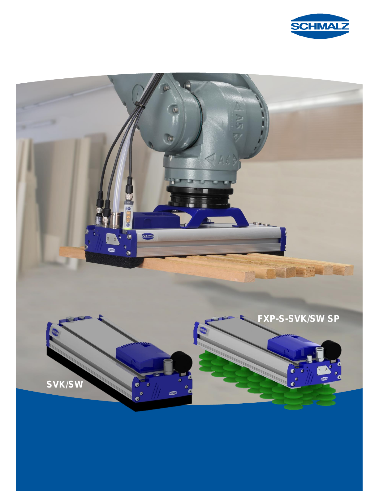
Vakuum-Flächengreifsystem FXP/FXP-S
Vacuum Area Gripping System FXP/FXP-S
FXP-SVK/SW
FXP-S-SVK/SW SPB2
Abbildung FXP-S inkl.
Sonderausstattung
FXP-S picture including
special equipment
Page 2

Bedienungsanleitung FXP(-S)-SVK / FXP(-S)-SW
Operating Instructions FXP(-S)-SVK / FXP(-S)-SW
30.30.01.01016 Status 10.2017 / Index 2
J. Schmalz GmbH
Johannes-Schmalz-Str. 1
D - 72293 Glatten
Tel +49 (0) 7443 / 2403 - 0
Fax +49 (0) 7443 / 2403 - 259
www.schmalz.com
[email protected]
Inhaltsverzeichnis / Contents
1. Sicherheits- und Gefahrenhinweise / Safety Notes and Warnings ............................................................. 1
1.1 Verwendete Symbole / Symbols used ................................................................................................................ 1
1.2 Allgemeine Sicherheitshinweise / General safety instructions ............................................................................ 1
1.3 Bestimmungsgemäße Verwendung / Intended use ............................................................................................ 3
1.4 Besondere Gefahren / Specific hazards ............................................................................................................. 3
1.5 Hinweis für den Benutzer des FXP/FXP-S-Greifers / Instructions for users of the gripper FXP/FXP-S .............. 4
2. Installation und Anschlüsse / Installation and connections ........................................................................ 5
2.1 Befestigung am Handling System / Mounting on the handling system ............................................................... 6
2.2 Einbau Manometer / Installing the gauge ........................................................................................................... 6
2.3 Anschluss Druckluft Ejektor / Connecting compressed air for the ejector ........................................................... 6
2.4 Anschluss Druckluft Abblasimpuls / Connecting compressed air for the blow-off pulse ..................................... 9
2.5 Anschluss Druckluft Vereinzelung/ Connecting the compressed air separation ............................................... 10
2.6 Elektrischer Anschluss und LED-Anzeige FXP-S / Electrical connection and LED indicator for FXP-S ........... 11
2.6.1 Elektrischer Anschluss FXP-S / Electrical connection for FXP-S ...................................................................... 11
2.6.2 LED-Anzeige / LED indicator ............................................................................................................................ 11
3. Funktionsbeschreibung / Function description .......................................................................................... 12
3.1 Funktionsbeschreibung – Komponenten / Description of functions – Components .......................................... 12
3.2 Funktionsbeschreibung Ventiltechnik SVK / Description of functions: SVK valve technology .......................... 16
4. Montage einzelner Komponenten / Mounting individual components ..................................................... 17
4.1 Montage Dichtplatte / Mounting the sealing plate ............................................................................................. 17
4.2 Montage Saugeranschlussleiste / Mounting the suction pad connection strip .................................................. 17
4.3 Montage Ventilfolie (SW und SVK –Folie ) / Mounting the valve film (SW and SVK film) ................................. 18
4.4 Montage Einschubejektor / Mounting the plug-in ejector .................................................................................. 19
5. Wartung / Maintenance .................................................................................................................................. 21
5.1 Wartungsplan / Maintenance plan .................................................................................................................... 22
Anhang / Appendix
EG-Herstellererklärung / EC-declaration of manufacture
Vor Inbetriebnahme des Greifers sind grundsätzlich die Sicherheitshinweise der ausführlichen Betriebsanleitung zu
beachten.
Es wird ausdrücklich darauf hingewiesen, dass diese Kurzanleitung keinen Anspruch auf Vollständigkeit erhebt.
Eine ausführliche Dokumentation des „Vakuum-Flächengreifsystem FXP/FXP-S“ kann auf www.schmalz.com
heruntergeladen werden.
The safety instructions in the complete operating instructions must always be observed before start of
operations with the gripper.
We particularly emphasize that these brief operating instructions make no claim to being exhaustive.
Detailed documentation of the large-area vacuum gripping system FXP/FXP-S can be downloaded from
www.schmalz.com.
Page 3
Bedienungsanleitung FXP(-S)-SVK / FXP(-S)-SW
Operating Instructions FXP(-S)-SVK / FXP(-S)-SW
30.30.01.01016 Status 10.2017 / Index 2
J. Schmalz GmbH
Johannes-Schmalz-Str. 1
D - 72293 Glatten
Tel +49 (0) 7443 / 2403 - 0
Fax +49 (0) 7443 / 2403 - 259
www.schmalz.com
[email protected]
Page -1-
1. Sicherheits- und Gefahrenhinweise / Safety Notes and Warnings
1.1 Verwendete Symbole / Symbols used
Dieses Symbol bezeichnet wichtige
Informationen und Hinweise.
Vorsicht!
Dieses Symbol bezeichnet eine möglicherweise gefährliche Situation.
Wenn Sie diese nicht meiden, können leichte
oder geringfügige Verletzungen die Folge sein.
Gefahr!
Dieses Symbol bezeichnet eine unmittelbar
drohende Gefahr.
Wenn Sie diese nicht meiden, können
schwerste Verletzungen und Tod die Folge
sein.
This symbol indicates important information
and instructions.
Caution
This symbol indicates a potentially dangerous
situation.
If it is not avoided, slight or minor injuries may
result.
Danger
This symbol indicates an immediate
hazard.
If it is not avoided, severe or fatal injuries
may result.
1.2 Allgemeine Sicherheitshinweise / General safety instructions
Diese Betriebsanleitung enthält wichtige
Informationen zum Umgang mit dem
Flächengreifer FXP / FXP-S. Bitte lesen Sie die
Betriebsanleitung sorgfältig durch und bewahren Sie diese
für spätere Zwecke auf.
These operating instructions contain important
information about working with the FXP/FXP-S
area gripper. Please read through the operating
instructions carefully and retain them for use at a later stage.
Der im Greifer eingebaute Ejektor erzeugt Lärm –
Gehörschutz tragen.
The ejector that is built into the gripper generates
noise – wear ear protection.
Die Abluftöffnung muss offen sein. Mit
geschlossener Abluftöffnung steigt der Innendruck
im Ejektor statisch über den maximal zulässigen
Betriebsdruck. Beschädigung des Ejektors und sogar
Verletzungsgefahr sind nicht auszuschließen.
The exhaust air outlet must be open. If the exhaust
air outlet is closed, the internal pressure in the
ejector will continue to rise until it exceeds the
maximum permitted operating pressure. This can result in
damage to ejector and/or injuries.
SEM-P Ejektoren wurden für einen maximalen
Betriebsdruck von 7,0 bar (0,7 MPa, 102 psi)
ausgelegt und dürfen höchstens mit diesem
Maximaldruck betrieben werden. Bei höherem Druck ist
Gefahr nicht auszuschließen.
SEM-P ejectors were designed for a maximum
operating pressure of 7.0 bar (0.7 MPa, 102 psi)
and must not be operated at pressures higher than
this. Higher pressures can lead to hazardous situations.
Nur die vorgesehenen Anschlussmöglichkeiten,
Befestigungsbohrungen und Befestigungsmittel
verwenden.
Use only the connections, mounting holes and
attachment materials that have been provided.
Niemals in saugende oder nicht saugende
Vakuumöffnungen (z.B. Vakuumanschlüsse
oder Sauggreifer) blicken.
Schwere Verletzungen können die Folge
sein. Augen können eingesogen werden.
Never look into any open or closed vacuum
vents (e.g. vacuum connections or suction
pads).
Severe injuries could occur as a result.
Eyes can be sucked in.
Page 4

Bedienungsanleitung FXP(-S)-SVK / FXP(-S)-SW
Operating Instructions FXP(-S)-SVK / FXP(-S)-SW
30.30.01.01016 Status 10.2017 / Index 2
J. Schmalz GmbH
Johannes-Schmalz-Str. 1
D - 72293 Glatten
Tel +49 (0) 7443 / 2403 - 0
Fax +49 (0) 7443 / 2403 - 259
www.schmalz.com
[email protected]
Page -2-
Weitere allgemeine Sicherheitshinweise:
Für sichere Installation und störungsfreien Betrieb sind
weiterhin u.a. folgende Verhaltensweisen nebeneinander zu
beachten und einzuhalten:
Die Bauteile sind den Verpackungen sorgfältig zu
entnehmen.
Die Bauteile sind generell vor Beschädigungen jeglicher
Art zu schützen
Bei Installation und Wartung: Bauteil, Gerät spannungs-
und druckfrei schalten und gegen unbefugtes Wieder
einschalten sichern.
Es dürfen keine Veränderungen an den Bauteilen
vorgenommen werden.
Sauberkeit im Umfeld und am Einsatzort
Anschlusssymbole und Bezeichnungen befinden sich auf
den Bauteilen und sind entsprechend zu beachten
Nur die vorgesehenen Anschlussmöglichkeiten sind zu
benutzen.
Pneumatische und elektrische Leitungsverbindungen
müssen dauerhaft mit dem Bauteil verbunden und
gesichert sein.
Der Greifer wird in Verbindung mit einem automatisierten
Handlings System (Portal / Roboter) eingesetzt. Deshalb
gelten außerdem die Sicherheitsvorschriften des
entsprechenden Systems.
Der Betrieb außerhalb der spezifizierten Leistungsgrenze
ist nicht zulässig. Fehlfunktion sowie Zerstörung können
die Folge sein.
Nichtbeachtung dieser vorgenannten Verhaltensweisen kann
zu Funktionsstörungen, Schäden und Verletzungen - auch
Lebensgefahr - führen.
Die Bauteile sind bei Außerbetriebstellung des Gerätes
umweltgerecht zu entsorgen!
Other general safety instructions:
For safe installation and trouble-free operation, the following
instructions must be observed and complied with:
Carefully remove the components from the packaging.
Protect the components from damage of any kind.
During installation and maintenance: Make sure that the
component and the device are disconnected,
depressurized and cannot be switched on again without
authorization.
Making changes to the components is not permitted.
Keep location of use and surroundings clean.
Observe the connection symbols and descriptions on the
components.
Use only the designated connections.
Pneumatic and electrical line connections must be
permanently connected and secured to the component.
The gripper is to be used in combination with an
automated handling system (gantry/robot). For this
reason, you must also follow the safety guidelines for the
relevant system.
Do not operate outside of the specified capacity. Doing
so may cause the device to malfunction or be destroyed.
Failure to observe the above instructions can lead to
malfunctions, damage, injury or death.
When the device is decommissioned, the components are to
be disposed of in an environmentally safe manner.
Page 5
Bedienungsanleitung FXP(-S)-SVK / FXP(-S)-SW
Operating Instructions FXP(-S)-SVK / FXP(-S)-SW
30.30.01.01016 Status 10.2017 / Index 2
J. Schmalz GmbH
Johannes-Schmalz-Str. 1
D - 72293 Glatten
Tel +49 (0) 7443 / 2403 - 0
Fax +49 (0) 7443 / 2403 - 259
www.schmalz.com
[email protected]
Page -3-
1.3 Bestimmungsgemäße Verwendung / Intended use
Der FXP/ FXP-S-Greifer dient zum Greifen und
Transportieren von Werkstücken aus saugfähigen
Materialien. Als zu evakuierendes Medium sind neutrale
Gase gemäß EN 983 zugelassen. Neutrale Gase sind z.B.
Luft, Stickstoff und Edelgase. Der Greifer ist nur für den
Einsatz im Automatikbetrieb und nicht für die manuelle
Handhabung ausgelegt. Mit dem Gerät darf nur im
abgesicherten Bereich (kein Betreten durch Personen
erlaubt) gearbeitet werden.
Der FXP/ FXP-S-Greifer wird an der kundenseitigen
Lastaufnahme über die dafür vorgesehenen T-Nuten
montiert. Die Steuerung erfolgt über ein kundenseitiges
Gerät.
Personen und Tiere befördern mit der Last oder dem FXP/
FXP-S-Greifer ist verboten!
Eigenmächtige Umbauten und Veränderungen des FXP/
FXP-S-Greifer sind aus Sicherheitsgründen verboten!
Die in dieser Betriebsanleitung vorgeschriebenen
Betriebs-, Wartungs- und Instandhaltungsbedingungen
müssen eingehalten werden.
Die zulässige Traglast darf nicht überschritten werden.
The gripper FXP/FXP-S is used for gripping and transporting
workpieces made of materials that allow suction. Neutral
gases in accordance with EN 983 are approved as
evacuation media. Neutral gases include air, nitrogen and
inert gases. The gripper is designed for automatic operation
and not for manual handling. Operations using the device
must take place in a secure area where no people are
allowed to enter.
The gripper FXP/FXP-S is mounted on the customerprovided load suspension device using the T-slots
designated for this purpose. The customer also provides a
control device.
No people or animals may be transported with the load or the
gripper FXP/FXP-S.
For safety reasons, modifications or changes may not be
made to the gripper FXP/FXP-S without approval.
The operating, maintenance and servicing conditions
specified in these operating instructions must be
observed.
The maximum permissible load may not be exceeded.
1.4 Besondere Gefahren / Specific hazards
Da die Last durch Unterdruck an den FXP/FXP-S-Greifer
gehalten wird, fällt sie herab sobald der Unterdruck
zusammenbricht. Dies geschieht bei plötzlichem
Energieausfall.
Niemals in saugende oder nicht saugende Vakuumöffnungen
(z.B. Vakuumanschlüsse, Ansaugöffnungen, Sauggreifer)
blicken.
Schwere Verletzungen können die Folge sein. Augen können
eingesogen werden.
Niemals in Druckluft- oder Abluftstrahl blicken.
Durch Vakuum können geschlossene Gefäße implodieren.
Because the load is held to the gripper FXP/FXP-S by a
vacuum, it is dropped as soon as the vacuum stops. This can
be caused by a sudden power failure.
Never look into any open or closed vacuum openings (e.g.
vacuum connections, suction openings or suction pads).
Severe injuries could occur as a result. Eyes can be sucked
in.
Never look into a stream of compressed air or exhaust air.
A vacuum can cause closed containers to implode.
Im Transportbereich der Nutzlast, die mit dem
Greifsystem bewegt wird, dürfen sich keine
Personen unter der Nutzlast aufhalten. Bei
Ausfall / Abfall der Vakuumerzeugung löst sich
die Last. Weitere Angaben unter „Sicherheits- und
Gefahrenhinweise“.
No person may sit or stand under the load in
the area in which the load is to be transported
by the gripper system. If vacuum generation
stops or decreases, the load is released. For
more information, see “Safety Notes and Warnings.”
Page 6
Bedienungsanleitung FXP(-S)-SVK / FXP(-S)-SW
Operating Instructions FXP(-S)-SVK / FXP(-S)-SW
30.30.01.01016 Status 10.2017 / Index 2
J. Schmalz GmbH
Johannes-Schmalz-Str. 1
D - 72293 Glatten
Tel +49 (0) 7443 / 2403 - 0
Fax +49 (0) 7443 / 2403 - 259
www.schmalz.com
[email protected]
Page -4-
1.5 Hinweis für den Benutzer des FXP/FXP-S-Greifers / Instructions for users of the
gripper FXP/FXP-S
Als Benutzer müssen Sie vor Inbetriebnahme des FXP/ FXPS-Greifer eingewiesen worden sein. Sie müssen die
Betriebsanleitung und besonders das Kapitel "Sicherheit"
gelesen und verstanden haben.
You must have been trained before starting operations with
the gripper FXP/FXP-S. You must have read and
understood the operating instructions, in particular the
“Safety” section.
Sorgen Sie dafür, dass nur autorisierte Personen mit dem
Gerät arbeiten. Sie sind im Arbeitsbereich des Gerätes
Dritten gegenüber verantwortlich.
Ensure that only authorized personnel use the device. You
are responsible for third parties in the working area of the
device.
Es gelten die örtlichen Sicherheitsvorschriften, in
Deutschland unter anderem die UVV 18.4/VBG 9a
"Lastaufnahmeeinrichtungen".
Local safety regulations apply. In Germany, this includes, but
is not limited to, UVV 18.4/VBG 9a “Load-bearing devices.”
Weitere Sicherheitshinweise in dieser Anleitung heben diese
nicht auf, sondern sind als Ergänzung zu verstehen.
The other safety instructions in this manual do not replace
these laws and regulations, but should be seen as a
supplement to them.
Page 7
Bedienungsanleitung FXP(-S)-SVK / FXP(-S)-SW
Operating Instructions FXP(-S)-SVK / FXP(-S)-SW
30.30.01.01016 Status 10.2017 / Index 2
J. Schmalz GmbH
Johannes-Schmalz-Str. 1
D - 72293 Glatten
Tel +49 (0) 7443 / 2403 - 0
Fax +49 (0) 7443 / 2403 - 259
www.schmalz.com
[email protected]
Page -5-
2. Installation und Anschlüsse / Installation and connections
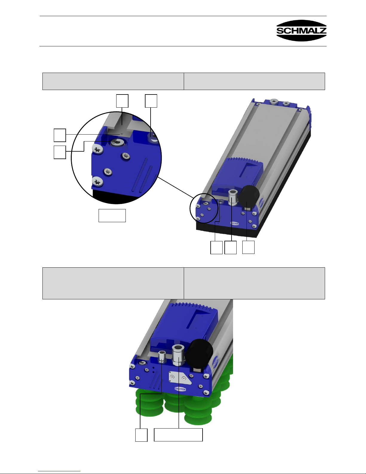
FXP – Standard
Druckluftanschluss 2 (Saugen EIN/AUS)
FXP – Standard
Compressed air connection 2 (Suction ON/OFF)
Abb. / Fig. 2-1
FXP-S – Standard
Integrierte Steuerventile für Saugen EIN/AUS , Abblasen
EIN/AUS und gemeinsamer Druckluftanschluss 2 und 3
FXP-S – Standard
Integrated control valve for “Suction ON/OFF,” “Blow off
ON/OFF” and for combined compressed air connection 2
and 3
Abb. / Fig. 2-2
6 5 8
2 und 3 / 2 and 3
Detail A
3
3
1
2
4
Page 8
Bedienungsanleitung FXP(-S)-SVK / FXP(-S)-SW
Operating Instructions FXP(-S)-SVK / FXP(-S)-SW
30.30.01.01016 Status 10.2017 / Index 2
J. Schmalz GmbH
Johannes-Schmalz-Str. 1
D - 72293 Glatten
Tel +49 (0) 7443 / 2403 - 0
Fax +49 (0) 7443 / 2403 - 259
www.schmalz.com
[email protected]
Page -6-
2.1 Befestigung am Handling System / Mounting on the handling system
Das Greifsystem wird über Nutensteine befestigt. Im
Grundkörper sind spezielle Nutensteinleisten (1) zur
Aufnahme der Nutensteine integriert. Die Adaption kann
direkt über die Nutensteinleiste, einen Roboterflansch oder
eine gefederte Aufhängung erfolgen. Entsprechende
Befestigungskits sind im Kapitel Zubehör aufgeführt
The gripping system is attached using sliding blocks. Special
sliding block strips (1) are integrated into the main body to
hold the sliding blocks. The system can be adapted directly
using the sliding block strip, a robot flange or a springmounted suspension eye. Suitable attachment kits are listed
in the “Accessories” section.
2.2 Einbau Manometer / Installing the gauge
Der Manometer (4 ) darf nur an der Seite wie in Abb. 2-1
abgebildet eingebaut werden, an der sich keine
Markierungen (6 ) in der Nutensteinleiste befindet . (Siehe
Detail A)
The gauge (4) may only be connected on the side where
there are no markings (6) in the sliding block strip, as shown
in Fig. 2-1. (See Detail A)
2.3 Anschluss Druckluft Ejektor / Connecting compressed air for the ejector
Für das Betreiben des Ejektors ist als Druckluftanschluss die
Steckverschraubung (2) vorgesehen. Verwenden Sie zum
Anschluss für die Druckluft (2) einen 12/9-PU-Schlauch
(maximale Länge 2 m).
Wir empfehlen, die Druckluftversorgung so weit wie möglich
mit dem max. möglichen Innendurchmesser zu verlegen. Ein
zu klein gewählter Innendurchmesser bewirkt, dass dem
Ejektor nicht genügend Druckluft für optimalen Betrieb
zugeführt wird.
The plug-in screw union (2) is intended as the compressed
air connection for operating the ejector. Use a 12/9 PU hose
(maximum length of 2 m) as a connector for the compressed
air (2).
We recommend using compressed air supply lines with the
max. possible internal diameter whenever possible. If a hose
with an insufficient internal diameter is used on the
compressed air side, the ejector will not receive enough
compressed air to operate at optimal capacity.
Page 9
Bedienungsanleitung FXP(-S)-SVK / FXP(-S)-SW
Operating Instructions FXP(-S)-SVK / FXP(-S)-SW
30.30.01.01016 Status 10.2017 / Index 2
J. Schmalz GmbH
Johannes-Schmalz-Str. 1
D - 72293 Glatten
Tel +49 (0) 7443 / 2403 - 0
Fax +49 (0) 7443 / 2403 - 259
www.schmalz.com
[email protected]
Page -7-
Optionales externes
Steuerventil Abblasen /
Optional external blow-off
control valve
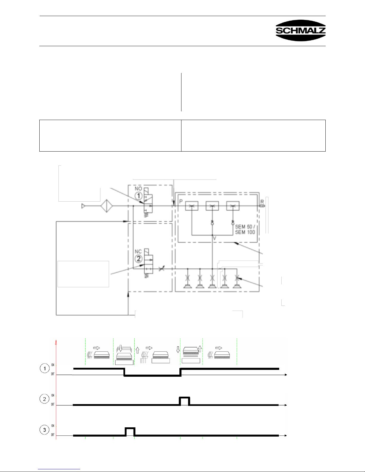
2.3.1 Pneumatische Schaltung FXP mit externen Steuerungsventilen /
FXP pneumatic circuit with external control valves
Für den FXP-Greifer mit externer Ansteuerung des Ejektors
kann optional der Steuerventil-Satz Saugen Ein/Aus
verwendet werden. Der Satz besteht aus allen erforderlichen
Komponenten wie Elektromagnetventil, Kabel,
Befestigungselemente und Schläuche (siehe Zubehör).
For the gripper FXP with an externally controlled ejector, the
control valve set “Suction on/off” can be used as an option.
The set contains all the required components, including the
solenoid valve, cables, mounting elements and hoses (see
“Accessories”).
Bei bauseitiger Verwendung der Steuerventile
Saugen Ein/ Aus und Abblasen Ein/Aus müssen die
verwendeten Ventile vakuumtauglich sein.
If the customer uses the “Suction on/off” and
“Blow off on/off” control valves, the valves used must be
suitable for vacuum applications.
Zeitdiagramm / Time diagram
Externe Steuerventil
Saugen EIN/AUS /
External control valve
Suction ON/OFF
Bauseits vom Kunden oder optional als Zubehör
Supplied by the customer or optionally as an
accessory
Fließdruck optimal 5.5-6.5 bar /
Optimum flowing compressed air pressure 5.5 to 6.5 bar
Vakuumerzeuger
(exemplarisch als pneumatischer
Vakuumerzeuger dargestellt) /
Vacuum generator (the example
shows a pneumatic vacuum generator)
Dargestellt Strömungswiderstand (SW) /
Flow restrictor displayed (SW)
Luftdruck im Greifer Innenraum max
0,2bar
Max. compressed air in the gripper
interior 0.2 bar
Page 10

Bedienungsanleitung FXP(-S)-SVK / FXP(-S)-SW
Operating Instructions FXP(-S)-SVK / FXP(-S)-SW
30.30.01.01016 Status 10.2017 / Index 2
J. Schmalz GmbH
Johannes-Schmalz-Str. 1
D - 72293 Glatten
Tel +49 (0) 7443 / 2403 - 0
Fax +49 (0) 7443 / 2403 - 259
www.schmalz.com
[email protected]
Page -8-
2.3.2 Pneumatische Schaltung FXP-S mit integrierten Steuerventilen /
FXP-S pneumatic circuit with integrated control valves
Der FXP-S-Greifer (siehe Abb. 2-2 und Abb. 2.4-2) ist mit
zwei integrierten Steuerventilen ausgerüstet, mit der
Funktion Saugen EIN / AUS und der Funktion Abblasen EIN
/ AUS. Für die Ansteuerung dieser beiden Ventile kann
optional das entsprechende Kabel zum Anschluss an Pos.
(8) verwendet werden (siehe Zubehör).
The FXP-S gripper (see Fig. 2-2 and Fig. 2.4-2) is equipped
with two integrated control valves with the functions “Suction
ON/OFF” and “Blow off ON/OFF.” To control the two valves,
the corresponding cable can also be used to connect it to
item (8) (see “Accessories”).
Steuerventil Saugen EIN/AUS /
Suction ON/OFF control valve
Steuerventil
Saugen EIN/AUS /
Control valve
Suction ON/OFF
Fließdruck optimal
5.5-6.5 bar /
Optimum flowing
compressed air
pressure 5.5 to 6.5 bar
Steuerventil Abblasen
EIN/AUS /
”Blow off ON/OFF”
control valve
Im Enddeckel integriert/
Integrated in end cover
Im Ejektorgehäuse/
In the ejector housing
Vakuumerzeuger
(exemplarisch als pneumatischer
Vakuumerzeuger dargestellt) /
Vacuum generator (the example
shows a pneumatic vacuum
generator)
Dargestellt Strömungsventil (SVK) /
Check valve displayed (SVK)
Steuerventil Abblasen EIN/AUS /
Blow off ON/OFF control valve
Luftdruck im Greifer Innenraum max
0,2bar
Max. compressed air in the gripper
interior 0.2 bar
Page 11
Bedienungsanleitung FXP(-S)-SVK / FXP(-S)-SW
Operating Instructions FXP(-S)-SVK / FXP(-S)-SW
30.30.01.01016 Status 10.2017 / Index 2
J. Schmalz GmbH
Johannes-Schmalz-Str. 1
D - 72293 Glatten
Tel +49 (0) 7443 / 2403 - 0
Fax +49 (0) 7443 / 2403 - 259
www.schmalz.com
[email protected]
Page -9-
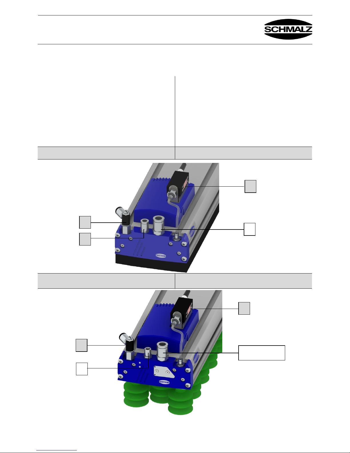
2.4 Anschluss Druckluft Abblasimpuls / Connecting compressed air for the blow-off
pulse
Der Anschluss für den Abblasimpuls (3) befindet sich im
Enddeckel. Dieser ist im Auslieferungszustand beim FXPGreifer mit einem Stopfen (3) (Abb. 2-1) verschlossen.
Der Schlauchanschluss für den Abblasimpuls (3) beim FXPGreifer muss an der „mittigen“ 1/8“-IG Gewindebohrungen
(3) erfolgen. (Abb. 2.4-1)
Der Schlauchanschluss für den Abblasimpuls (2,3) beim
FXP-S- Greifer ist der Gleiche ¼-“ Anschluss wie für den
Ejektor (Abb. 2.4-2). Mit dem zweiten Steuerventil am
Enddeckel wird die Druckluft zum Abblasen umgeleitet.
The connection for the blow-off pulse (3) is located on the
end cover. When the gripper FXP is delivered, this
connection is closed with a plug (3) (Fig. 2-1).
For the gripper FXP, the hose for the blow-off pulse (3) must
be connected on the “middle” 1/8" female tapped holes (3).
(Fig. 2.4-1)
For the gripper FXP-S, the hose connection for the blow-off
pulse (2, 3) is the same ¼" connection used for the ejector
(Fig. 2.4-2). The second control valve on the end cover
diverts the compressed air for the blow-off function.
FXP mit optionalen Teilen für Abblasen (3), Vereinzelung (5)
und Anschluss Vakuumschalter (7) (siehe Zubehör)
FXP with optional parts for blowing off (3), separation (5)
and connecting vacuum switches (7) (see “Accessories”)
Abb. / Fig. 2.4-1
FXP-S mit optionalen Teilen für Vereinzelung (5)
und Anschluss Vakuumschalter (7) (siehe Zubehör)
FXP-S with optional parts for separation (5) and connecting
vacuum switches (7) (see “Accessories”)
Abb. / Fig. 2.4-2
5
7 3 2
5
7
8
2 und 3 / 2 and 3
Page 12
Bedienungsanleitung FXP(-S)-SVK / FXP(-S)-SW
Operating Instructions FXP(-S)-SVK / FXP(-S)-SW
30.30.01.01016 Status 10.2017 / Index 2
J. Schmalz GmbH
Johannes-Schmalz-Str. 1
D - 72293 Glatten
Tel +49 (0) 7443 / 2403 - 0
Fax +49 (0) 7443 / 2403 - 259
www.schmalz.com
[email protected]
Page -10-
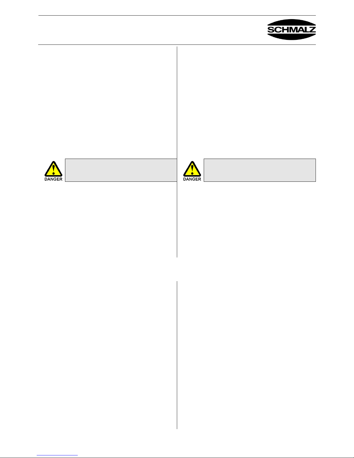
Zum schnellen Ablegen der angesaugten Werkstücke und
zur Realisierung schneller Zykluszeiten sollte beim FXPGreifer der Steuerventil-Satz Abblasen ein/aus verwendet
werden. Dieser enthält alle benötigten Bauteile wie
Elektromagnetventil, Kabel, Befestigungselemente und
Schläuche (siehe Zubehör).
Bei Nichtgebrauch des Abblasimpulses ist der Anschluss im
Enddeckel des FXP-Greifers mit dem mitgelieferten Stopfen
(3) zu verschließen!
Beim FXP-S-Greifers ist das Steuerventil für den
Abblasimpuls schon im Greifer integriert. (siehe
pneumatisches Schaltbild unter 2.3.2)
Es ist darauf zu achten, dass beim Aufgeben des
Abblasimpulses der Greifer mit Werkstück nicht auf eine
feste Auflage gedrückt ist. Ein „freies Lösen“ des
Werkstücks vom Greifer muss erfolgen können.
Der Staudruck im Greifer darf beim Abblasen
max. 0,2 bar betragen.
Anschluss elektrisch
Betrieb der optionalen Steuerventile mit 24 V DC,
ausschließlich über Netzgeräte mit Schutzkleinspannung
(PELV) gemäß EN60204.
Statt einer analogen Vakuumanzeige Pos. (4) Abb.2-1 kann
auch eine digitale Anzeige über ein Vakuumschalter (7)
erfolgen
Anschluss evtl. optionaler Vakuumschalter siehe Abb. 2.4-1,
Pos. (7).
To quickly deposit gripped workpieces and to achieve quick
cycle times, the control valve set “Blow off on/off” should be
used with the gripper FXP. This includes all required
components such as the solenoid valve, cables, mounting
elements and hoses (see Accessories).
If the blow-off pulse is not used, the connection in the end
cover of the gripper FXP must be sealed with the included
plug (3).
For the gripper FXP-S, the control valve for the blow-off
pulse is already integrated in the gripper. (see pneumatic
circuit diagram in 2.3.2)
Before initiating the blow-off pulse, ensure that the
gripper (with attached workpiece) is not pressed against
a solid surface. The workpiece must be able to freely
detach from the gripper.
The dynamic pressure in the gripper must
not be more than 0.2 bar during blow-off.
Electrical connection
The optional control valves are to be operated with 24 V DC
and only with power supply units with protected extra-low
voltage (PELV) in accordance with EN60204.
In place of an analog vacuum gauge (item (4), Fig. 2-1), a
vacuum switch (7) can also be used as a digital gauge.
See Fig. 2.4-1, item (7) for connecting an optional vacuum
switch.
2.5 Anschluss Druckluft Vereinzelung/ Connecting the compressed air separation
Der Anschluss (5) Abb. 2-1 für den optionalen
Vereinzelungsimpuls befindet sich im Enddeckel (siehe
Abb.2.4-1 und 2.4-2). Dieser ist im Auslieferungszustand mit
einem Stopfen (5) (siehe Abb. 2-1; Detail A) verschlossen.
Der Druckluftanschluss ( 5 ) für die Vereinzelung ist nur an
der Seite anzuschließen, an der sich die Markierungen (6,
siehe Detail A; Abb. 2-1) der Nutensteinleiste befinden. Die
Markierungen sind jeweils an den Enden des Profils
gesetzt.Die Druckluftstärke ist über die Drosselschraube je
nach Erfordernis bauseits einzustellen.
Der Vereinzelungsimpuls wird dann benötigt, wenn zwei
oder mehrere luftdurchlässige Platten beim Ansaugen mit
angehoben werden. Der kurz eingebrachte Druckluftimpuls
trennt die zweite Platte von der Ersten.
Diese Einstellung an der Drosselschraube kann je nach
Beschaffenheit der Werkstücke variieren.
Weitere Details zur Vereinzelungsfunktion finden Sie in
Kapitel 10.
The connection (5) (Fig. 2-1) for the optional separation
pulse is located in the end cover (see Fig. 2.4-1 and 2.4-2).
When the gripper is delivered, this connection is closed with
a plug (5) (see Fig. 2-1, Detail A). The compressed air
connection (5) for separation should only be connected on
the side with the markings (6, see Detail A, Fig. 2-1) of the
sliding block strip. The markings are on either end of the
section. The amount of compressed air can be set to the
customer’s requirements using the valve screw.
The separation pulse is needed when two or more airpermeable sheets are picked up during suction. The briefly
applied compressed air pulse separates the second sheet
from the first.
The valve screw setting can vary according to the properties
of the workpieces.
Additional details on the separation function can be found in
section 10.
Page 13
Bedienungsanleitung FXP(-S)-SVK / FXP(-S)-SW
Operating Instructions FXP(-S)-SVK / FXP(-S)-SW
30.30.01.01016 Status 10.2017 / Index 2
J. Schmalz GmbH
Johannes-Schmalz-Str. 1
D - 72293 Glatten
Tel +49 (0) 7443 / 2403 - 0
Fax +49 (0) 7443 / 2403 - 259
www.schmalz.com
[email protected]
Page -11-
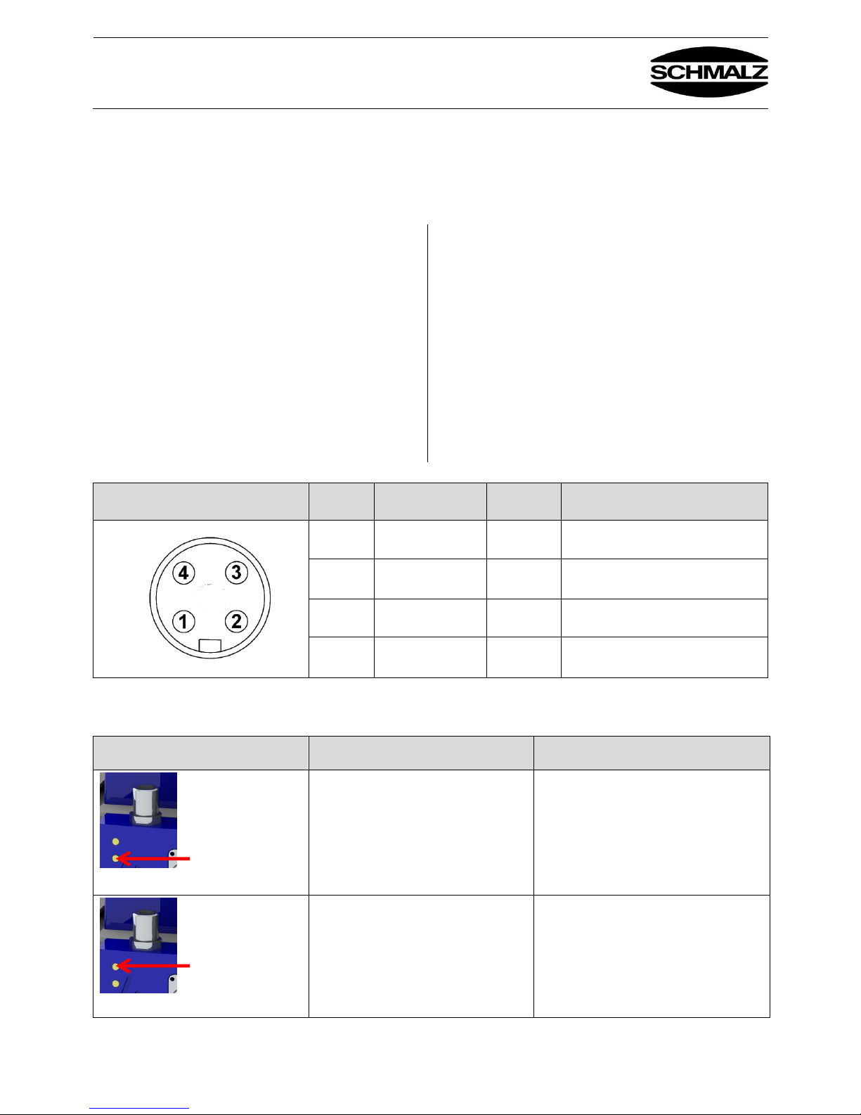
2.6 Elektrischer Anschluss und LED-Anzeige FXP-S / Electrical connection and LED
indicator for FXP-S
2.6.1 Elektrischer Anschluss FXP-S / Electrical connection for FXP-S
Der elektrische Anschluss des Ejektors im FXP-S erfolgt
über einen 4-poligen M12-Stecker. 24V DC ± 10%, Max.
Leistungsaufnahme 2 W, Nennstrom 0,1 A.
For FXP-S, the ejector’s electrical connection is established
using a 4-pin M12 connector. 24 V DC ± 10%, max. power
input: 2 W, rated current: 0.1 A.
Standard = PNP-Schaltend. Sonderausführung NPNSchaltend auf Anfrage verfügbar.
Standard = PNP switching. Special NPN switching design
available on request.
Die Steckverbinder dürfen nicht unter Spannung verbunden
oder getrennt werden.
The plug connectors may not be connected or disconnected
when the system is live.
Der Betrieb des Ejektors ist ausschließlich über Netzgeräte
mit Schutzkleinspannung (PELV) gestattet. Es ist für sichere
elektrische Trennung der Versorgungsspannung gemäß
EN60204 zu sorgen.
The ejector may only be operated using power supply units
with protected extra-low voltage (PELV). The system must
incorporate safe electrical cut-off of the power supply in
compliance with EN60204.
Die maximale Leitungslänge für die Versorgungsspannung
und die Signaleingänge und Signalausgänge beträgt 30 m.
The power supply, signal inputs and signal outputs have a
maximum line length of 30 meters.
Stecker / Plug
Pin
Litzenfarbe /
Lead color
Symbol
Funktion / Function (PNP)
1
Braun / Brown
Nicht belegt / Not used
2
Weiß / White
Signaleingang „Saugen“ AUS /
“Suction OFF” signal input
3
Blau / Blue
Masse / Ground
4
Schwarz / Black
Signaleingang „Abblasen“ EIN /
“Blow off ON” signal intput
2.6.2 LED-Anzeige / LED indicator
LED
Zustand LED / LED status
Zustand Ventil / Valve status
Ventil „Saugen“ / “Suction” valve
LED leuchtet / LED illuminated
LED leuchtet nicht / LED not illuminated
“Saugen” AUS / “Suction OFF”
“Saugen” EIN / “Suction ON”
Ventil „Abblasen“ / “Blow off” valve
LED leuchtet / LED illuminated
LED leuchtet nicht / LED not illuminated
“Abblasen” EIN / “Blow off” ON
“Abblasen” AUS / “Blow off” OFF
Page 14
Bedienungsanleitung FXP(-S)-SVK / FXP(-S)-SW
Operating Instructions FXP(-S)-SVK / FXP(-S)-SW
30.30.01.01016 Status 10.2017 / Index 2
J. Schmalz GmbH
Johannes-Schmalz-Str. 1
D - 72293 Glatten
Tel +49 (0) 7443 / 2403 - 0
Fax +49 (0) 7443 / 2403 - 259
www.schmalz.com
[email protected]
Page -12-
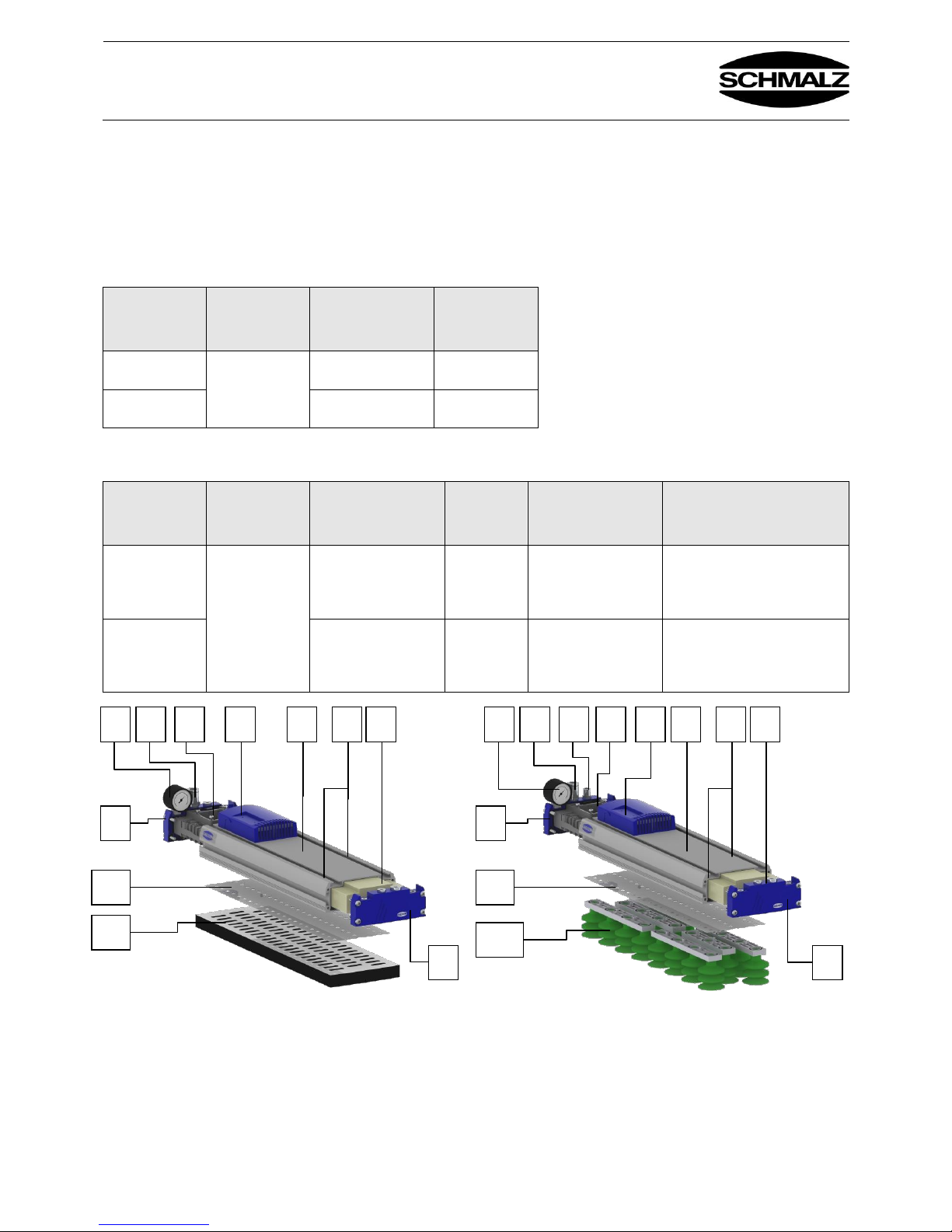
3. Funktionsbeschreibung / Function description
3.1 Funktionsbeschreibung – Komponenten / Description of functions – Components
Variantenübersicht / Version overview
FXP / FXP-S mit Dichtplatte / FXP/FXP-S with sealing plate
Ventiltechnik /
Valve
technology
Länge des
Greifers [mm] /
Length of the
gripper [mm]
Saugreihenanzahl
/ Number of
suction rows
Lochraster
[mm] /
Hole spacing
[mm]
SW
442 … 1432
3R = 3 Saugreihen /
3R = 3 suction rows
18
SVK
5R = 5 Saugreihen /
5R = 5 suction rows
18
FXP /FXP-S mit Saugern / FXP/FXP-S with suction pads
Ventiltechnik /
Valve
technology
Länge des
Greifers [mm] /
Length of the
gripper [mm]
Saugreihenanzahl /
Number of suction
rows
Lochraster
[mm] / Hole
spacing
[mm]
Sauggreifertypen
und Faltenanzahl /
Suction pad types
and number of folds
Sauggreifererdurchmesser
[mm] und Anschlussform /
Suction pad diameter [mm]
and connection type
SW
442 ... 1432
3R = 3 Saugreihen /
3R = 3 suction rows
54
SPB2 = Typ SPB2 mit
2,5 Falten /
40 P = 40mm Durchmesser
mit Einsteckkopf (Push In) / 40
P = 40mm diameter with pushin head
SVK
5R = 5 Saugreihen /
5R = 5 suction rows
36
SPB2 = Typ SPB2 mit
2,5 Falten /
20 P = 20mm Durchmesser
mit Einsteckkopf (Push In) / 20
P = 20mm diameter with pushin head
FXP mit Dichtplatte / FXP with sealing plate FXP-S mit Saugern / FXP-S with suction pads
6
5
3 6 4 8 1 2 7
6
10
11
5
3 6 4 8 1 2 7
6
10
12/13
9
Page 15
Bedienungsanleitung FXP(-S)-SVK / FXP(-S)-SW
Operating Instructions FXP(-S)-SVK / FXP(-S)-SW
30.30.01.01016 Status 10.2017 / Index 2
J. Schmalz GmbH
Johannes-Schmalz-Str. 1
D - 72293 Glatten
Tel +49 (0) 7443 / 2403 - 0
Fax +49 (0) 7443 / 2403 - 259
www.schmalz.com
[email protected]
Page -13-
Oberteil:
1 Grundkörper FXP / FXP-S
Der Grundkörper besteht aus längenvariablem
Aluminiumstrangpressprofil, mit einem integriertem
Druckluftkanal für die Vereinzelungsfunktion (siehe
Sonderausführung: Vereinzelungsfunktion)
Standardlängen 442 / 640 / 838 / 1234 / 1432 mm
Top part:
1 Main body FXP/FXP-S
The main body consists of a length-adjustable extrusionmolded aluminum section with an integrated compressed air
duct for the separation function (see
“Special Model with the Separation Function”)
Standard lengths 442 / 640 / 838 / 1234 / 1432 mm
2 Nutensteinleisten FXP / FXP-S
Die Nutenleisten dienen zur flexiblen mechanischen
Befestigung des Greifers über Nutensteine.
Entsprechende Befestigungskits sind im Kapitel Zubehör
aufgeführt. Die seitlichen Nutenleisten bieten die
Möglichkeit der Anbindung von Sensoren und
Zusatzbauteile.
2 Sliding block strips FXP/FXP-S
The t-slots are used for flexible mechanical attachment of the
gripper using the sliding blocks.
Suitable attachment kits are listed in the “Accessories”
section. The t-slots on the side offer the option of
connecting sensors and additional components.
3 Druckluftanschluss FXP / FXP-S
Der Anschluss der Druckluft erfolgt über einen ¼“
Steckverschraubung für einen Druckluftschlauch mit 12mm
Außendurchmesser. Siehe auch Kapitel Abmessungen. Bei
Greifern länger als 838mm sind an beiden Enddeckel ein
Druckluftanschluss vorgesehen.
4 Einschubejektor FXP / FXP-S
Der Einschubejektor ist in Leichtbauweise ausgeführt und
leicht zu tauschen. Er ist alternativ mit 1-4 MehrstufenEjektorsträngen zur optimalen Leistungsanpassung
verfügbar. Der Anschluss ist für 12/9-Schlauch ausgelegt.
Bei einer Länge ab 2 m ist ein Schlauch mit größerem
Innendurchmesser zu wählen.
Der Fließdruck direkt vor dem Ejektor darf 5,5 bar nicht
unterschreiten und 7 bar nicht überschreiten. Die
Überwachung mittels Druckmanometer wird empfohlen!
Siehe nachfolgendes separates Kapitel.
3 Compressed air connection FXP/FXP-S
The compressed air is connected via a ¼" plug-in screw
union for a compressed air hose with a 12 mm outside
diameter. See also the “Dimensions” section. For grippers
longer than 838 mm, a compressed air connection is
provided on both end covers.
4 Plug-in ejector FXP/FXP-S
The plug-in ejector has a lightweight design and is easy to
replace. It is also available with 1-4 multi-stage ejector
chains for optimal performance adjustment. The connection
is designed for a 12/9 hose. For lengths longer than 2 m, a
hose with a larger internal diameter must be selected.
The flowing compressed air pressure directly in front of the
ejector must not fall below 5.5 bar or exceed 7 bar. We
recommend monitoring the pressure using a pressure gauge.
See the separate section below.
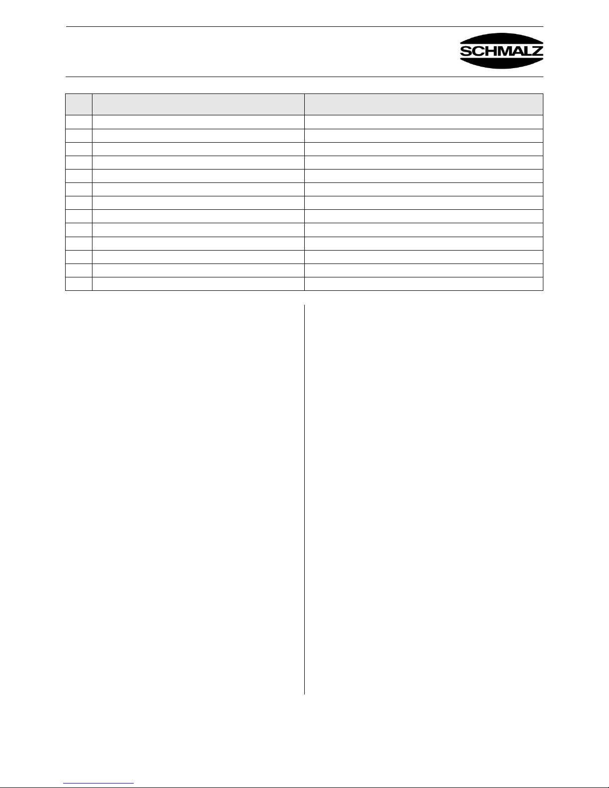
Pos./
Item
Bezeichnung
Designation
1
Grundkörper
Main body
2
Nutensteinleiste
Sliding block strip
3
Druckluftanschluss
Compressed air connection
4
Einschubejektor
Plug-in ejector
5
Vakuum Manometer
Vacuum gauge
6
Enddeckel
End cover
7
Einschubelement (zur Strömungsoptimierung )
Insert element (for optimizing the flow)
8
Schalldämmgehäuse
Silencer housing
9
Stecker für Anschluss Steuerkabel nur beim FXP-S
Plug for connecting control cable, only for FXP-S
10
Ventilfolie
Valve film
11
Dichtplatte (optional mit integrierter Filtersiebmatte)
Sealing plate (with integrated filter screen mat as an option)
12
Saugeranschlussleiste
Suction pad connection strip
13
Sauggreifer (Stecksauger)
Suction pad (plug-in suction pad)
Page 16
Bedienungsanleitung FXP(-S)-SVK / FXP(-S)-SW
Operating Instructions FXP(-S)-SVK / FXP(-S)-SW
30.30.01.01016 Status 10.2017 / Index 2
J. Schmalz GmbH
Johannes-Schmalz-Str. 1
D - 72293 Glatten
Tel +49 (0) 7443 / 2403 - 0
Fax +49 (0) 7443 / 2403 - 259
www.schmalz.com
[email protected]
Page -14-
6 Enddeckel FXP / FXP-S
Der Enddeckel verfügt über ein 1/4"-Innengewinde für den
Druckluftanschluss und über drei 1/8“- Gewinde für weitere
Anschlüsse. Diese erlauben beim FXP-Greifer den
Anschluss eines Vakuummanometers oder Vakuumschalters
und die Zuführung eines Druckluftimpulses für Abblasen und
Vereinzelung. (Die Druckluftzuführung für die Vereinzelung
ist nur auf der Seite der Markierungsbohrungen an zu
bringen.)
Beim FXP-S-Greifer gibt es nur einen Druckluftanschluss
(1/4“) für den Ejektor und Abblasimpuls. Durch die zwei
integrierten Steuerventile wird die Druckluft entsprechend
umgeleitet.
6 End cover FXP/FXP-S
The end cover has a 1/4" female thread for the compressed
air connection and three 1/8" threads for additional
connections. These allow a vacuum gauge or a vacuum
switch to be connected and a compressed air pulse to be
supplied for blow-off and separation for a gripper FXP.
(The compressed air supply for separation may only be
attached on the side with the marking holes.)
For a gripper FXP-S, there is only one compressed air
connection (1/4") for the ejector and the blow-off pulse. The
two integrated control valves are used to divert the
compressed air as needed.
7 Einschubelement FXP / FXP-S
Das Einschubelement wurde zur Strömungsoptimierung
entwickelt und darf insbesondere bei der SVK-Ventiltechnik
nicht entfernt werden.
8 Schalldämmgehäuse FXP / FXP-S
Das Schalldämmgehäuse ist mit Dämmmaterial ausgekleidet
und dient zur Reduzierung des Abluftschalls Zur Reinigung
kann das Gehäuse schnell abgeschraubt und das
Dämmmaterial mit Druckluft gereinigt werden.
9 Stecker für Steuerkabelanschluss FXP-S
Den Steueranschluss gibt es nur bei der FXP-S –Version mit
integrierten Steuerventilen für Saugen EIN/AUS und
Abblasen EIN / AUS
7 Insert element FXP/FXP-S
The insert element was developed to optimize the flow and
may not be removed, particularly when using the SVK valve
technology.
8 Silencer housing FXP/FXP-S
The silencer housing is lined with sound-dampening material
and serves to reduce the exhaust noise. For cleaning, the
housing can be quickly unscrewed and the dampening
material can be cleaned with compressed air.
9 Plug for control cable connection FXP-S
The control connection is only present on the FXP-S version
with integrated control valves for “Suction ON/OFF” and
“Blow off ON/OFF.”
Unterteil:
10 Ventilfolie FXP / FXP-S
Die Ventilfolie gibt es in der Gestaltung als SW-Folie und
SVK-Folie, in den beiden Saugreihenarten 3R und 5R.
Mit dieser Folie lässt sich der Greifer sehr schnell von
der SW- Technik in die SVK- Technik umrüsten.
Die Flächengreifer arbeiten mit SW bzw. SVK-Ventiltechnik.
Die Ventiltechnik SVK wird bei Anwendungen mit sehr
schnellen Zykluszeiten eingesetzt (z.B. Richtwert für das
Ablegen der Werkstücke mit aktivem Abblasimpuls: ca.
0,3 sec.). Zudem ist das Ansaugverhalten für raue und
strukturierte Oberflächen optimiert.
Optimaler Arbeitszyklus siehe unten.
Lower part:
10 Valve film FXP/FXP-S
The valve film is available as an SW film or an SVK film,
each of which is available in suction row types 3R and 5R.
This plastic film allows the gripper to be quickly converted
from the SW technology to the SVK technology.
The area grippers work with SW and SVK valve technology.
The SVK valve technology is used for applications with very
fast cycle times (e.g. benchmark for depositing of workpieces
with active blow-off pulse: approx. 0.3 sec.) The suction
properties are also optimized for rough and textured
surfaces.
See below for the optimal working cycle.
Page 17
Bedienungsanleitung FXP(-S)-SVK / FXP(-S)-SW
Operating Instructions FXP(-S)-SVK / FXP(-S)-SW
30.30.01.01016 Status 10.2017 / Index 2
J. Schmalz GmbH
Johannes-Schmalz-Str. 1
D - 72293 Glatten
Tel +49 (0) 7443 / 2403 - 0
Fax +49 (0) 7443 / 2403 - 259
www.schmalz.com
[email protected]
Page -15-
11 Dichtplatte FXP / FXP-S
Die Dichtplatte besteht aus einem technischen Schaum.
Das Raster ist verfügbar in 3R LL-20x7 (ab Werkstückbreite
25mm) und 5R LL-12x5 (ab Werkstückbreite 20mm). Die
Dichtplatte ist asymmetrisch gelocht und für einen schnellen
Wechsel ausgelegt. Näheres siehe Kapitel Montage.
Optional gibt es eine Dichtplatte mit selbst reinigender
Filtersiebmatte. Das Eindringen von Schmutz wird dadurch
vermieden und die Wartungsintervalle werden verlängert.
Hinweis zu Eigenschaften von Schäumen:
Schäume unterliegen produktionsbedingt Schwankungen
bzgl. der technischen Eigenschaften und des optischen
Eindrucks. Es liegt in der Verantwortung des Anwenders die
Eignung eines Schaumes für eine spezifische Anwendung
zu testen. Gerne unterstützen wir Sie bei der Erstbestellung
durch Greiftests in unserem Hause mit Ihren OriginalMusterwerkstücken.
Da auch die Schaumhöhe Toleranzen unterliegt wird
empfohlen bei jedem Schaumwechsel die Höheneinstellung
des Greifers nach zu justieren (Optimal 50% Schaumkompression beim Ansaugen der zu hebenden Werkstücke), um optimale Funktion und Schaumlebensdauer zu
realisieren.
Durch die Walkarbeit wird der Schaum luftdurchlässiger.
Bei Erreichen einer hohen Arbeitszyklenzahl, kann ein
Schaumwechsel nötig werden ohne dass dies optisch
sichtbar erscheint.
Der Schaum darf nicht mit der Druckluftpistole gereinigt
werden. Dadurch wird der Schaum an diesen Stelle
luftdurchlässig.
11 Sealing plate FXP/FXP-S
The sealing plate is made of technical foam. The grid is
available in 3R LL-20x7 (workpieces that are 25 mm or wider)
and 5R LL-12x5 (workpieces that are 20 mm or wider). The
sealing plate has asymmetric holes and is designed for fast
replacement. For details, see the “Assembly” section.
An optional sealing plate with a self-cleaning filter screen mat
is also available. This prevents contamination and extends the
maintenance intervals.
Note on foam properties:
The technical properties and appearance of foams may vary
due to production conditions. The user is responsible for
testing whether a foam is suitable for a specific application.
We would be happy to assist you in placing your first order by
performing grip tests at our premises if you provide us with
your original workpieces.
As the foam height is also subject to tolerances, it is
recommended that you adjust the height setting of the gripper
every time the foam is replaced (50% foam compression
before the workpiece is picked up is optimal). This ensures
that the gripper functions optimally and that the service life of
the foam is not reduced.
This flexing makes the foam more permeable to air. When a
high number of working cycles is reached, it may be
necessary to replace the foam, even if there is no visible
indication of wear.
The foam may not be cleaned with a compressed-air gun.
This would make the foam permeable to air in the places
where compressed air was applied.
FXP / FXP-S mit Saugern:
12 & 13 Saugeranschlussleiste mit Stecksaugern
Die Hauptanwendung des FXP und FXP-S mit Saugern ist
das Ansaugen von nicht eigenstabilen Teilen
Die Saugeranschlussleisten gibt es mit Stecksaugern ohne
und mit integrierter Filterplatte. Die Leisten werden an den
speziell dafür vorgesehen Grundkörper geschraubt.
Die Sauger werden in den Durchmessergrößen 20, und
40mm mit 2,5 Falten angeboten, optional mit integrierter
Filterplatte. Jeder Sauger kann ohne Werkzeug separat
gewechselt werden.
Saugerleisten mit 1/8“ Innengewinde
Für Sonderanwendungen können auch optional Sauger mit
1/8“-Anschlussnippel eingesetzt werden. Hierzu werden die
entsprechenden Saugerleisten mit 1/8“ IG angeboten. (siehe
auch Zubehör unter Kapitel 8.6)
FXP/FXP-S with suction pads:
12 & 13 Suction pad connection strip with plug-in suction
pads
The FXP and FXP-S with suction pads are primarily used for
gripping parts that are not rigid.
The suction pad connection strips are available with plug-in
suction pads with and without filter plates. The strips are
screwed onto the main body intended especially for this
purpose.
The suction pads are available in diameters of 20 and 40 mm
with 2.5 folds. An optional integrated filter plate is also
available. Every suction pad can be changed separately
without tools.
Suction pad strips with 1/8" female thread
Optional suction pads with 1/8" connection nipples can also
be used for special applications. Corresponding suction pad
strips with 1/8" female threads are offered for this purpose.
(See accessories in section 8.6)
Page 18
Bedienungsanleitung FXP(-S)-SVK / FXP(-S)-SW
Operating Instructions FXP(-S)-SVK / FXP(-S)-SW
30.30.01.01016 Status 10.2017 / Index 2
J. Schmalz GmbH
Johannes-Schmalz-Str. 1
D - 72293 Glatten
Tel +49 (0) 7443 / 2403 - 0
Fax +49 (0) 7443 / 2403 - 259
www.schmalz.com
[email protected]
Page -16-
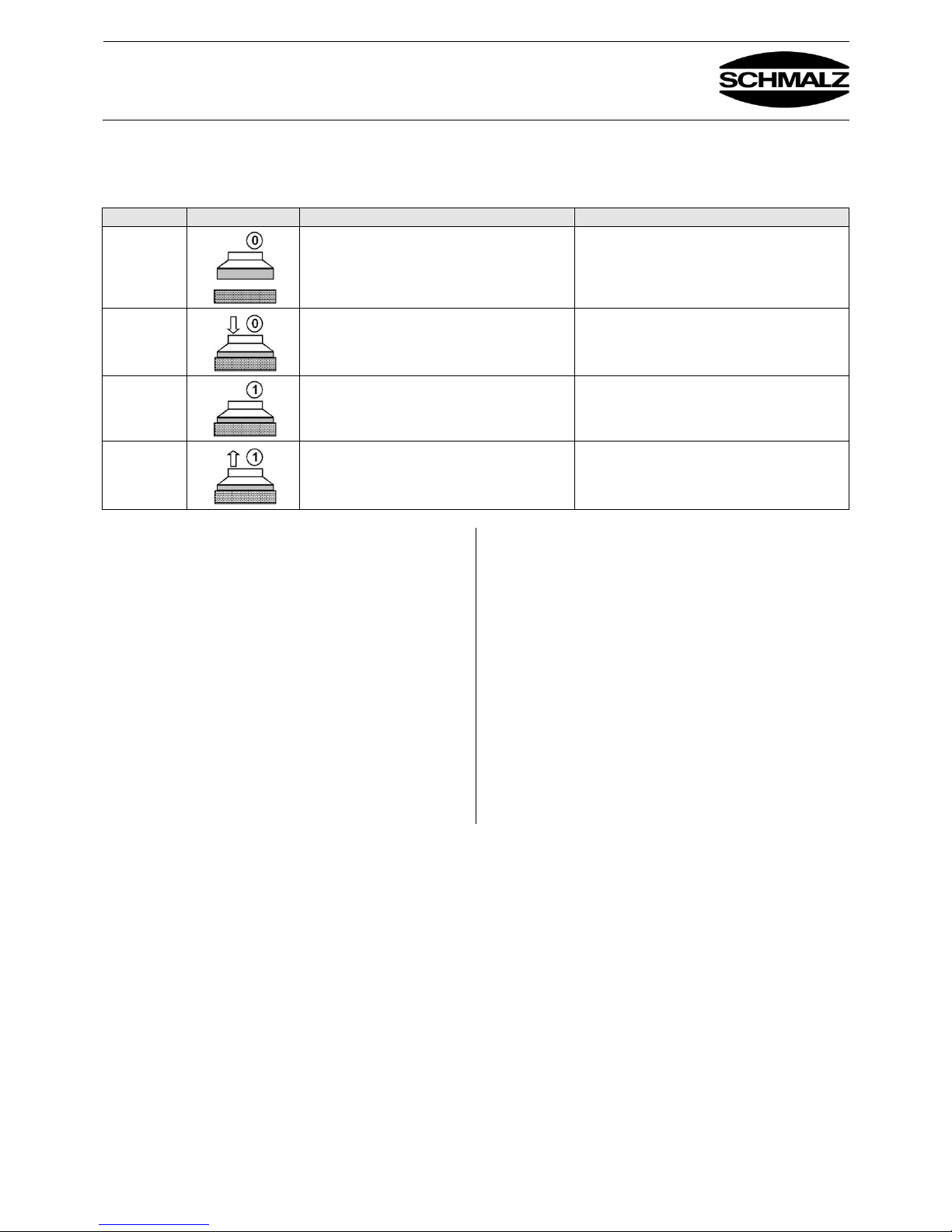
3.2 Funktionsbeschreibung Ventiltechnik SVK / Description of functions: SVK valve
technology
Schritt / Step
Bezeichnung
Designation
1
Vakuumerzeugung ausschalten bzw. Ejektor
von der Druckluftzufuhr trennen*
Switch off vacuum generation and/or
disconnect ejector from the compressed air
supply.
2
Greifer auf Werkstück aufsetzen – Dichtplatte
/ Sauggreifer sollte min. 40 %
zusammengedrückt werden
Set the gripper down on the workpiece – the
sealing plate/suction pad should be 40%
compressed.
3
Druckluft für den Ejektor zuschalten
Supply compressed air to the ejector.
4
Werkstück mittels Vakuum anheben
Lift the workpiece using the vacuum.
* Bei der Ventiltechnik SW kann mit eingeschaltetem Ejektor
auf das Werkstück aufgesetzt werden.
* Grippers with valve technology SW can be placed on the
workpiece when the ejector is switched on.
Hinweis
Die optimale Funktionalität steht bei der Ventiltechnik SVK
zur Verfügung, wenn der Greifer horizontal eingesetzt wird.
Bei schräg gestelltem oder bei Schwenkvorgängen ist das
Abdichtverhalten auf rauen / strukturierten
Werkstückoberflächen etwas eingeschränkt.
Note
The valve technology SVK functions optimally when the
gripper is used horizontally. For swiveling operations or
movements at an incline, the sealing properties for
workpieces with rough/textured surfaces it somewhat limited.
Maximal zulässiger Schwenkwinkel gegenüber der
Horizontalen bei SVK: 60°
Maximal zulässige Beschleunigung in vertikaler Richtung
bei SVK: 5m/s²
Nachsaugen oder späteres Aufnehmen weiterer Produkte
nicht möglich!
Maximum permitted swivel angle relative to the horizontal
for SVK: 60°
Maximum permitted acceleration in a vertical direction for
SVK: 5 m/s²
It is not possible to provide additional suction or pick up
other products afterward.
Page 19
Bedienungsanleitung FXP(-S)-SVK / FXP(-S)-SW
Operating Instructions FXP(-S)-SVK / FXP(-S)-SW
30.30.01.01016 Status 10.2017 / Index 2
J. Schmalz GmbH
Johannes-Schmalz-Str. 1
D - 72293 Glatten
Tel +49 (0) 7443 / 2403 - 0
Fax +49 (0) 7443 / 2403 - 259
www.schmalz.com
[email protected]
Page -17-
4. Montage einzelner Komponenten / Mounting individual components
4.1 Montage Dichtplatte / Mounting the sealing plate
Ablösen alte Dichtplatte
Dichtplatte abziehen (Ventilfolie verbleibt auf
Greiferprofil)
Eventuelle Klebereste und Schmutzreste entfernen
SW-Bohrungen in der Ventilfolie dürfen nicht verstopft
sein, ggf. reinigen! (Sichtprüfung gegen Licht)
Removing the old sealing plate
Remove the sealing plate (valve film remains on the
gripper section).
Remove any adhesive residues or dirt.
The SW bores in the valve film must not become blocked.
Clean them if necessary! (Visual inspection against a
light source)l inspection against a light source)
Montage neuer Dichtplatte
Die Dichtplatte ist
asymmetrisch!
Ausrichtung
beachten!
Schutzpapier entfernen
Dichtplatte fest, vollflächig
und faltenfrei aufdrücken.
Anpressdruck ca. 20 N/cm² Eventuell mit einer Walze
andrücken
Öffnungen in der Dichtplatte und Bohrungen im
Grundkörper müssen fluchten!
Hinweis: Die Oberfläche muss frei sein von: Staub, Öl,
Oxiden und Kleberesten
Verarbeitungstemperatur: Für Objekt und
Umgebungstemperatur ist ein Bereich von +10 °C bis
+40 °C empfohlen.
Hinweis: Nach dem Aufkleben des Schaums sollte dieser
mindestens für 1 Stunden nicht eingesetzt werden, damit der
Kleber vollständig abbindet.
Mounting a new sealing plate
The sealing plate is
asymmetrical. Observe
the alignment.
Remove protective paper.
Press the sealing plate firmly
onto the entire surface without
any wrinkles.
Use a surface pressure of approx. 20 N/cm²
Openings in the sealing plate and holes in the main body
must line up.
Note: The surface must be free of: Dust, oil,
oxides and adhesive residues
Processing temperature: A range of +10 °C to +40 °C is
recommended for the object and ambient temperature.
Note: After you have glued on the foam, it should not be
used for at least one hour so that the adhesive has time to
set completely.
4.2 Montage Saugeranschlussleiste / Mounting the suction pad connection strip
Sollte die Ventilfolie bei Flächengreifern mit
Saugeranschlussleisten (Abb. 4.3-2) gewechselt werden,
müssen alle Saugeranschlussleisten abgeschraubt werden.
Die Montage der Saugeranschlussleisten ist derart
aufgebaut, dass zu Beginn immer ganze Leisten mit vier
Saugern bei Saugerdurchmesser 40mm und sechs Saugern
bei Saugerdurchmesser 20mm verwendet werden.
If you need to change the valve film on area grippers with
suction pad connection strips (Fig. 4.3-2), you must unscrew
all the suction pad connection strips. The suction pad
connection strips are designed to have whole strips of four
suction pads with a suction pad diameter of 40 mm and six
suction pads with a suction pad diameter of 20 mm mounted
first.
Am Ende des Flächengreifers können auch kürzere Leisten
moniert sein.
Then shorter strips can be mounted at the end of the area
gripper.
Bei der Demontage der Saugeranschlussleisten markieren
Sie bitte diese Stellen an der kürzere Leisten eingebaut
wurden. Diese Makierung gewährleistet dann wieder die
richtige Reihenfolge bei Wiederanschrauben der
Saugeranschlussleisten. Das Anzugsdrehmoment beträgt
2Nm.
When removing the suction pad connection strips, please
mark the places where shorter strips were installed. These
markings will ensure that the suction pad connection strips
are screwed back on in the correct order. The torque is 2Nm.
Video
www.schmalz.com/
dichtschaum-wechseln
video
www.schmalz.com/
sealing-foam-
replacement
Page 20
Bedienungsanleitung FXP(-S)-SVK / FXP(-S)-SW
Operating Instructions FXP(-S)-SVK / FXP(-S)-SW
30.30.01.01016 Status 10.2017 / Index 2
J. Schmalz GmbH
Johannes-Schmalz-Str. 1
D - 72293 Glatten
Tel +49 (0) 7443 / 2403 - 0
Fax +49 (0) 7443 / 2403 - 259
www.schmalz.com
[email protected]
Page -18-
4.3 Montage Ventilfolie (SW und SVK –Folie ) / Mounting the valve film (SW and SVK
film)
Wahlweise ist sowohl die Ventilfolie SW und die Ventilfolie
SVK bei gleichem Dichtplattenraster an den Grundkörper
aufklebbar. Beim Tausch der Ventilart SW zur Ventilart SVK
müssen zuvor die vom Hersteller vorgeschriebenen
Kugelventile in die Öffnung des Grundkörpers eingelegt
werden. Um die Ventilfolie einfach abzuziehen sind am
Deckel kleine Ausfräsungen vorgesehen. (Abb. 4.3-1)
Vor Aufbringen der Ventilfolie ist darauf zu achten,
dass die Klebefläche des Grundkörpers frei von
Rückstanden und fettfrei ist.
Zu Wartungszwecken ( z.B. Reinigen der Ventilsitze ) sollte
die gleiche Ventilfolie nicht mehr als 4-6 mal wieder
aufgeklebt werden. Es ist zu beachten, dass nach Abziehen
der Ventilfolie über Kopf die Ventilkörper heraus fallen.
Daher muss der Greifer vor dem Abziehen der Folie
demontiert und um 180° gedreht aufgelegt werden. Die
Klebeseite der Ventilfolie ist nach dem Abziehen vor Staub
zu schützen.
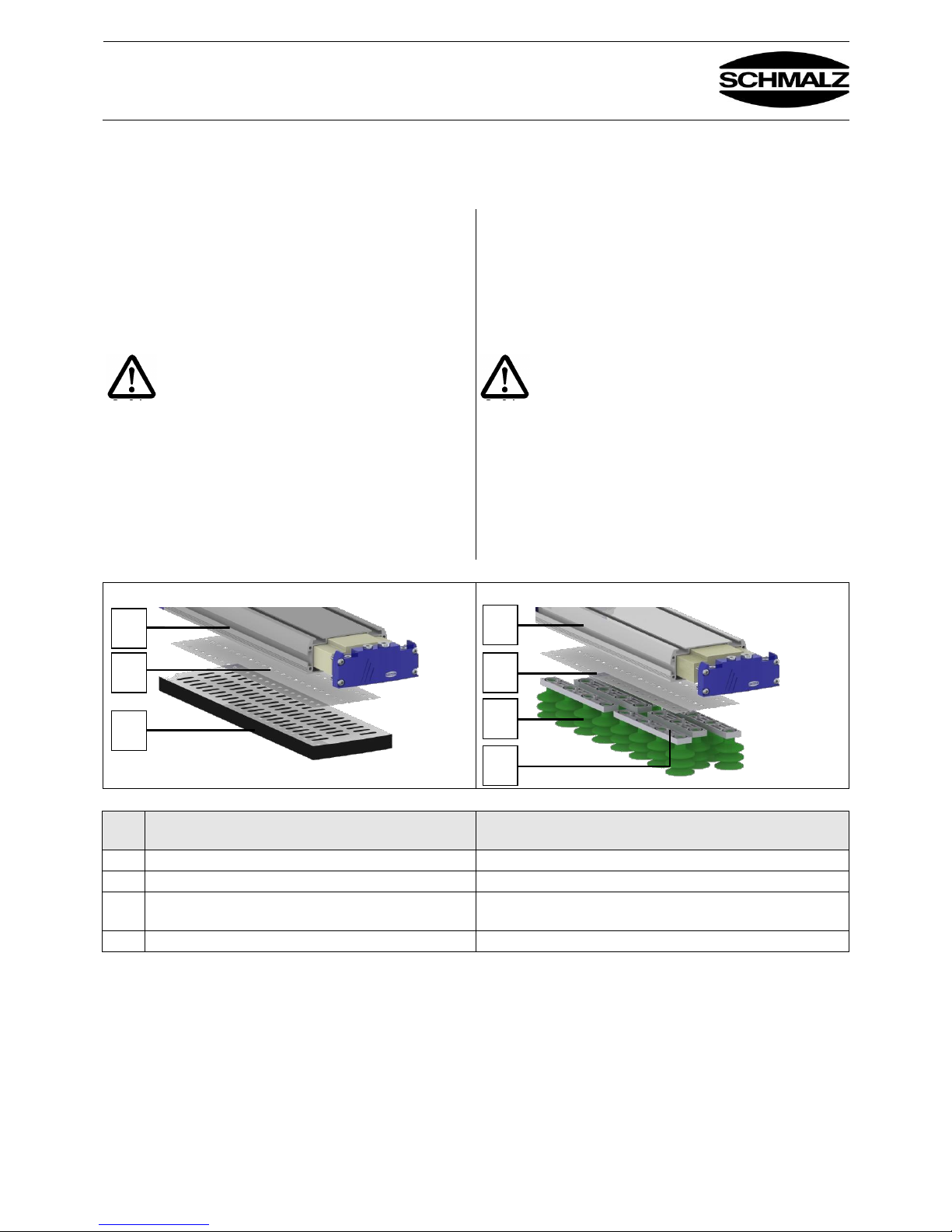
The same sealing plate grid can be used to glue either the
valve film SW or the valve film SVK to the main body. When
switching from valve type SW to valve type SVK, you must
first insert the ball valves specified by the manufacturer into
the opening in the main body. Small recesses in the cover
make it easy to pull off the valve film. (Fig. 4.3-1)
Before applying the valve film, ensure that the
surface of the main body is free of residues and
grease.
The same valve film should not be reattached more than 4-6
times for maintenance purposes (e.g. cleaning the valve
face). Please note that if you remove the valve film above
head height, the valve bodies will fall out. For this reason, the
gripper must be disassembled and rotated 180° before the
film is removed. The adhesive side of the valve film must be
protected from dust after removal.
Abb./Fig. 4.3-1
Abb./Fig. 4.3-2
Pos /
Item
Bezeichnung
Designation
1
Grundkörper
Main body
2
Ventilfolie (SW oder SVK-Ausführung)
Valve film (SW or SVK design)
3
Ansaugelement (Dichtplatte oder
Saugeranschlussleiste)
Suction element (sealing plate or suction pad connection strip)
4
Schrauben M4 für Saugeranschlussleiste (2Nm)
M4 screws for suction pad connection strip (2 Nm)
1 2 3 1 2 3 4
Page 21
Bedienungsanleitung FXP(-S)-SVK / FXP(-S)-SW
Operating Instructions FXP(-S)-SVK / FXP(-S)-SW
30.30.01.01016 Status 10.2017 / Index 2
J. Schmalz GmbH
Johannes-Schmalz-Str. 1
D - 72293 Glatten
Tel +49 (0) 7443 / 2403 - 0
Fax +49 (0) 7443 / 2403 - 259
www.schmalz.com
[email protected]
Page -19-
4.4 Montage Einschubejektor / Mounting the plug-in ejector
Zur optimalen Leistungsanpassung an die jeweilige
Anwendung sowie zur einfachen Durchführung von
Wartungsarbeiten kann der im Flächengreifer integrierte
Einschubejektor ausgebaut werden.
The plug-in ejector integrated in the area gripper can be
removed in order to optimize the performance for the
particular application and to allow for easy maintenance.
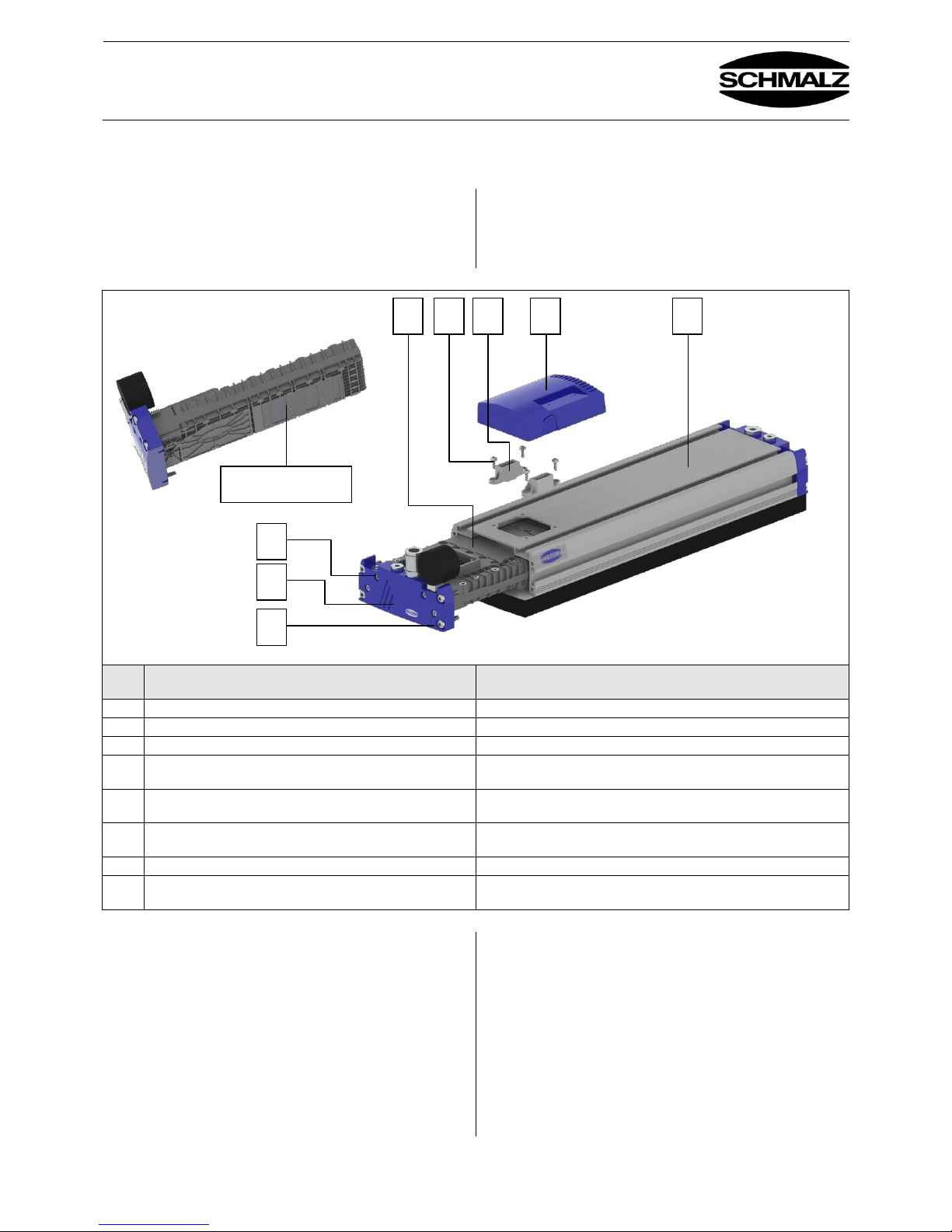
Abb. / Fig. 4.3
Pos /
Item
Bezeichnung
Designation
1
Grundkörper
Main body
2
Schalldämmgehäuse
Silencer housing
3
Einschubejektor
Plug-in ejector
4
Befestigungsschrauben für Basiselement und
Einschubejektor
Fastening screws for base element and plug-in ejector
5
Basiselement zum einclipsen des
Schalldämmgehäuses
Base element for clipping in the silencer housing
6
Befestigungsschrauben Ejektordeckel zum
Grundkörper
Fastening screws for connecting the ejector cover to the main
body
7
Enddeckel Einschubejektor
End cover for plug-in ejector
8
Befestigungsschrauben Einschubejektor zum
Enddeckel
Fastening screws for connecting the plug-in ejector to the end
cover
Ausbau Einschubejektor
Schalldämmgehäuse (2) abziehen.
4x Befestigungsschrauben (4) sowie Basiselemente (5)
entfernen.
4x Befestigungsschraube (6) am Enddeckel (7) entfernen,
Schaum unterhalb des Deckels lösen,
Einschubejektor herausziehen.
4x Befestigungsschraube (8) entfernen. Darauf achten, dass
beim Lösen des Ejektors vom Enddeckel die Federn im
Kolben des Ejektors nicht verloren gehen.
Removing the plug-in ejector
Remove the silencer housing (2).
Remove the 4 fastening screws (4) and base element (5).
Remove the 4 fastening screws (6) on the end cover (7),
loosen the foam below the cover and
pull out the plug-in ejector.
Remove the 4 fastening screws (8). When removing the
ejector from the end cover, be sure not to lose the
springs in the ejector pistons.
1 2 3 4 5 6 7 8 Filter / filter
Page 22
Bedienungsanleitung FXP(-S)-SVK / FXP(-S)-SW
Operating Instructions FXP(-S)-SVK / FXP(-S)-SW
30.30.01.01016 Status 10.2017 / Index 2
J. Schmalz GmbH
Johannes-Schmalz-Str. 1
D - 72293 Glatten
Tel +49 (0) 7443 / 2403 - 0
Fax +49 (0) 7443 / 2403 - 259
www.schmalz.com
[email protected]
Page -20-
Einbau Einschubejektor
Ejektor (3) mit 4x Befestigungsschraube (8) an Enddeckecke
(7) montieren (2,3 Nm). Darauf achten, dass die Federn
im Kolben des Ejektors vorhanden sind.
Einschubejektor in Grundkörper einschieben
4x Befestigungsschraube (4) mit Befestigungselement an der
Flächengreiferoberseite leicht anziehen (1 Nm) bis sich
Befestigungsschrauben (6) am Ejektordeckel leicht
einschieben lassen
4x Befestigungsschraube (6) am Enddeckel (7) leicht
anziehen (0,5 Nm)
4x Befestigungsschraube (4) an Flächengreiferoberseite
wieder etwas lösen - 2 Umdrehungen!
4x Befestigungsschraube (6) am Enddeckel fest anziehen
(4 Nm)
4x Befestigungsschraube (5) an der Flächengreiferoberseite
fest anziehen (1,2 Nm)
Schalldämmgehäuse (2) einclipsen
Installing the plug-in ejector
Mount the ejector (3) onto the end cover corner (7) using the
4 fastening screws (8) (2.3 Nm). Ensure that the springs
are in the ejector pistons.
Slide the plug-in ejector into the main body.
Gently tighten (1 Nm) the 4 fastening screws (4) with the
fastening element on the top side of the area gripper until
the fastening screws (6) on the ejector cover slide in
easily.
Gently tighten (0.5 Nm) the 4 fastening screws (6) on the end
cover (7).
Loosen the 4 fastening screws (4) on the top side of the area
gripper by about 2 revolutions.
Firmly tighten (4 Nm) the 4 fastening screws (6) on the end
cover.
Firmly tighten (1.2 Nm) the 4 fastening screws (5) on the top
side of the area gripper.
Clip in the silencer housing (2).
Page 23
Bedienungsanleitung FXP(-S)-SVK / FXP(-S)-SW
Operating Instructions FXP(-S)-SVK / FXP(-S)-SW
30.30.01.01016 Status 10.2017 / Index 2
J. Schmalz GmbH
Johannes-Schmalz-Str. 1
D - 72293 Glatten
Tel +49 (0) 7443 / 2403 - 0
Fax +49 (0) 7443 / 2403 - 259
www.schmalz.com
[email protected]
Page -21-
5. Wartung / Maintenance
Bei äußerer Verschmutzung mit Lappen und Seifenlauge
(max. 60 °C) reinigen.
Durch den Betrieb des Flächengreifers kann aus der
Umgebung Staub eingesaugt werden. Dieser Staub sammelt
sich an definierter Verschmutzungsstelle (Filter vor dem
Einschubejektor) im Flächengreifer. Je nach Menge an
eingesaugtem Staub müssen diese Siebe regelmäßig
gereinigt werden.
Die erforderlichen Wartungsintervalle können durch
folgende einfache Maßnahmen deutlich verlängert werden.
Remove any dirt on the exterior with a soft cloth and soap
suds (max. 60 °C).
Operation of the area gripper can draw in dust from the
environment. This dust collects at a particular contamination
point within the area gripper (the filter before the plug-in
ejector). These screens must be cleaned regularly,
depending on the amount of dust sucked in.
The necessary maintenance intervals can be increased
considerably by taking the following measures.
Optimierte Ansteuerung
Saugen nur dann einschalten, wenn Werkstücke gehoben
werden. Ansonsten wird zusätzlich Staub aus der Umgebung
mit eingesaugt, was die erforderlichen Wartungsintervalle
verkürzt.
Optimized control
Only turn on the suction when workpieces are being lifted.
Otherwise, additional dust from the environment is drawn in,
which shortens the necessary maintenance intervals.
Verwendung von Dichtplatten mit integriertem Filtervlies
Durch einen Filtervlies wird verhindert, dass Staub in den
Flächengreifer eingesaugt wird. Da das Filtervlies die
Walkbewegung der Dichtplatte bei jedem Arbeitszyklus
mitmacht tritt ein Selbstreinigungseffekt des Filtervlieses auf.
Use of sealing plates with integrated filter fleece
A filter fleece prevents dust from being drawn into the area
gripper. Because the filter fleece makes the flexing
movements along with the sealing plate in each working
cycle, the filter fleece is self-cleaning.
Verwendung von Saugern mit integrierter Filterplatte
Durch eine Filterplatte wird verhindert, dass Staub in den
Flächengreifer eingesaugt wird. Es wird empfohlen die
Filterplatte regelmäßig mit Druckluft zu reinigen.
Use of suction pads with integrated filter plate
A filter plate prevents dust from being drawn into the area
gripper. We recommend that
you regularly clean the filter plate with compressed air.
Weitere Wartungsarbeiten sind in der Regel nicht erforderlich. Bei starker Verschmutzung kann es zu Betriebsstörungen kommen, wir empfehlen dann eine Überholung
durch die J. Schmalz GmbH.
Wechseldichtplatten sind im Kapitel Ersatz- und Verschleißteile beschrieben.
Bei mechanischer Beschädigung der Dichtplatte, kann
diese bis zu einem gewissen Grad mit handelsüblichem
Vulkanisationskleber wieder hergestellt werden (z.B. Kleber
zur Reparatur von Fahrradschläuchen)
Generally, no other maintenance is necessary. Heavy
contamination can cause malfunctions. We recommend
overhaul by J. Schmalz GmbH in this case.
The replaceable sealing plates are described in the “Spare
Parts and Wearing Parts” section.
If the sealing plate shows physical damage, it can be
repaired up to a certain point using standard vulcanizing
adhesive (e.g. adhesive for repairing the inner tubes of
bicycles).
Page 24
Bedienungsanleitung FXP(-S)-SVK / FXP(-S)-SW
Operating Instructions FXP(-S)-SVK / FXP(-S)-SW
30.30.01.01016 Status 10.2017 / Index 2
J. Schmalz GmbH
Johannes-Schmalz-Str. 1
D - 72293 Glatten
Tel +49 (0) 7443 / 2403 - 0
Fax +49 (0) 7443 / 2403 - 259
www.schmalz.com
[email protected]
Page -22-
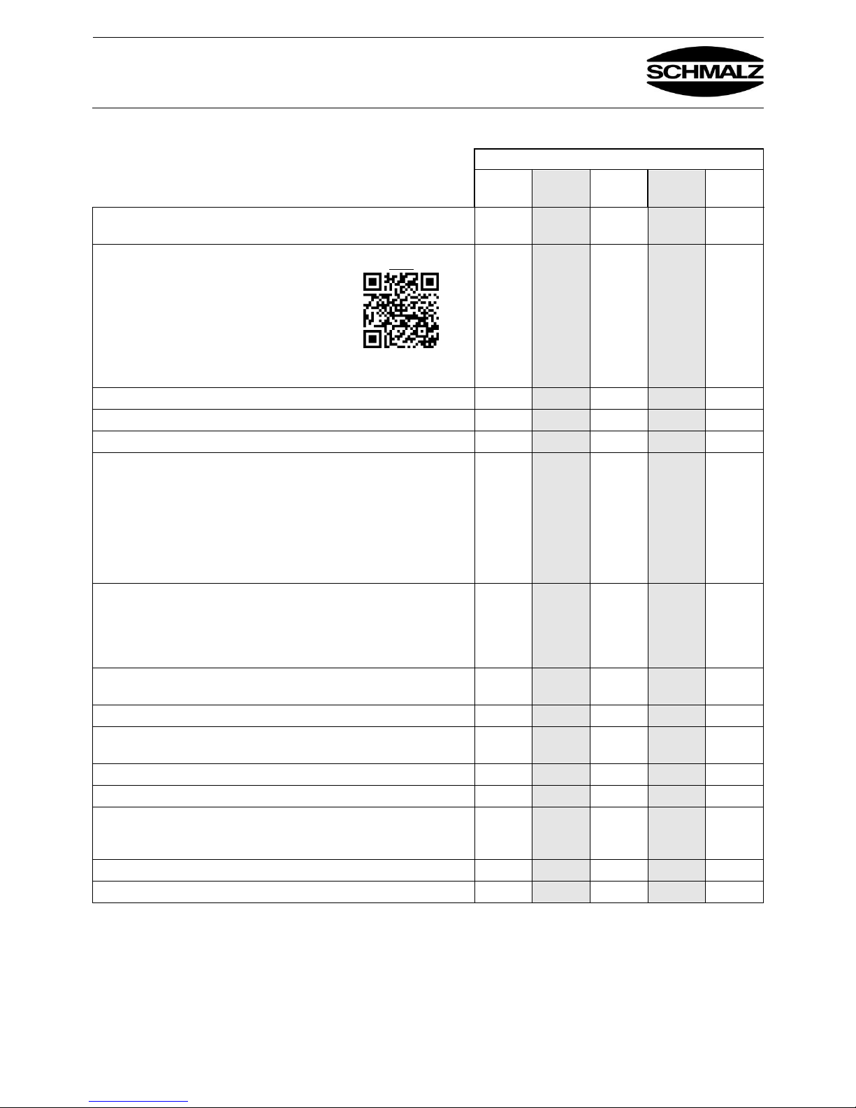
5.1 Wartungsplan / Maintenance plan
Intervall
täglich
wöchentl-
ich
monatlich
1/2-
jährlich
jährliche
Prüfung
Überprüfung tragender Teile (z.B. Aufhängung) auf Verformung,
Verschleiß oder sonstige Beschädigung
X X
Dichtplatten oder Sauger kontrollieren,
kein Verschleiß, Risse, Undichtheiten,
gegebenenfalls austauschen
X X
Prüfung ob optionales Filtervlies verschmutzt ist
X X
Prüfung ob optionale Filterplatte der Sauger verschmutzt ist
X X
Allgemeiner Zustand des Gerätes
X
Dichtheitsprüfung
Bei eingeschaltetem Ejektor und mit vollflächig angesaugtem glatten
luftundurchlässigem Werkstück (z.B. Metallplatte) muss der
Systemunterdruck am Vakuummanometer (siehe Kap. 3; Pos. 5) einen
Unterdruck anzeigen, der den maximalen erreichbaren Unterdruck des
verwendeten Ejektors um maximal 20% unterschreitet. Beispiel: Ejektor
erreicht maximal -0,55bar. Am Manometer muss ein Unterdruck
zwischen -0,45 und -0,55bar angezeigt werden
X X
Vakuumprüfung
Bei eingeschaltetem Ejektor und ohne angesaugtes Werkstück muss
der Systemunterdruck am Vakuummanometer einen Unterdruck
zwischen -0,20 und -0,4bar anzeigen. Bei FXP –Flächengreifer mit
SVK-Ventiltechnik zwischen 0,35 – 0,55bar
X X
Sichtprüfung der Strömungsventile und Strömungswiderstände auf
Verschmutzung
X X
Ist der Staubfilter gereinigt? (Abb. 4.3)
X X
Sind die Druckluftschläuche in gutem Zustand (nicht brüchig, nicht
geknickt, keine Scheuerstellen und damit dicht?)
X X
Ist das Typenschild noch auf dem Gerät?
X
Ist die Bedienungsanleitung noch vorhanden und den Arbeitern bekannt
X
Dichtplatte mit weicher Bürste und Staubsauger reinigen und z.B.
Holzspäne und Staubablagerungen entfernen. Nicht mit Druckluft
abblasen. Der harte Druckluftstrahl zerstört die Struktur des Schaums
X
Verbindungen und Schrauben, etc. überprüfen und nachziehen
X
Druckleitungen und Anschlüsse auf Leckage prüfen
X
Hinweis: Aufhängung, Druckschläuche, Druckfilter sind kein Bestandteil des Gerätes FXP.
Video
www.schmalz.com/
dichtschaum-wechseln
Page 25
Bedienungsanleitung FXP(-S)-SVK / FXP(-S)-SW
Operating Instructions FXP(-S)-SVK / FXP(-S)-SW
30.30.01.01016 Status 10.2017 / Index 2
J. Schmalz GmbH
Johannes-Schmalz-Str. 1
D - 72293 Glatten
Tel +49 (0) 7443 / 2403 - 0
Fax +49 (0) 7443 / 2403 - 259
www.schmalz.com
[email protected]
Page -23-
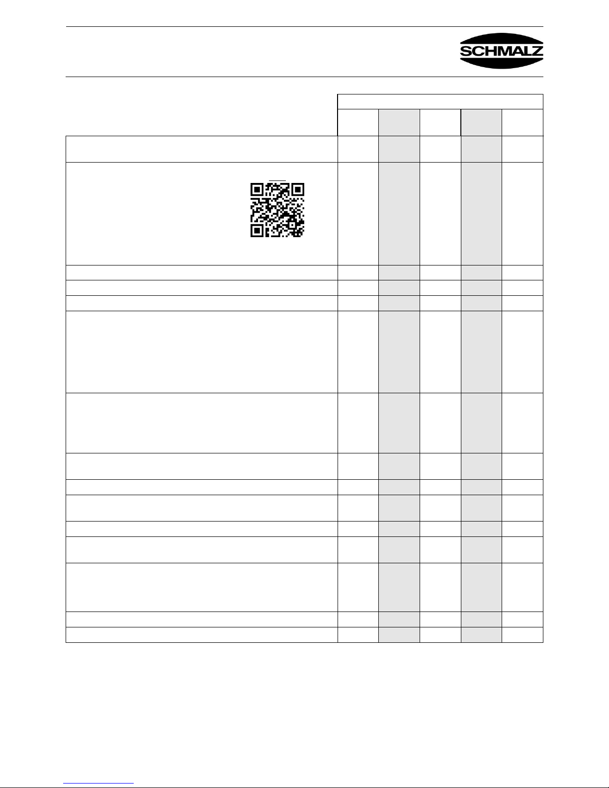
Interval
Daily
Weekly
Monthly
Every six
months
Annual
check
Check all load-bearing parts (e.g. suspension) for deformation, wear or
other damage
X X
Check the sealing plates or suction
pads for wear, cracks and leaks;
replace if necessary
X X
Check whether the optional filter fleece is dirty
X X
Check whether the optional suction pad filter plate is dirty
X X
General condition of the device
X
Leak test
When the ejector is switched on and the smooth, non-permeable
surface of a workpiece (e.g. a metal plate) is fully picked up, the system
vacuum at the vacuum gauge (see Section 3, Item 5) must indicate a
vacuum that is no more than 20% lower than the maximum possible
vacuum of the ejector used. Example: Ejector reaches max. -0.55 bar.
A vacuum between -0.45 and -0.55 bar must be shown on the gauge.
X X
Vacuum test
When the ejector is switched on and no workpiece is picked up, the
system vacuum at the vacuum gauge must indicate a vacuum between
-0.20 and -0.4 bar. For the large-area gripper FMP with SVK valve
technology, between -0.35 and -0.5 bar
X X
Visual inspection of the check valves and flow resistors to see whether
they are contaminated
X X
Has the dust filter been cleaned? (Fig. 4.3)
X X
Are the compressed air hoses in good condition (not brittle, not kinked,
no worn sections and no leaks)?
X X
Is the type plate still on the device?
X
Are the operating instructions still available and are workers familiar
with them?
X
Clean the sealing plate with a soft brush and a vacuum cleaner, and
remove wood chips, dust, etc. Do not blow off with compressed air.
The force of the stream of compressed air would destroy the structure
of the foam
X
Check and adjust connections, screws, etc.
X
Check hose lines and connections for leakage
X
Note: Suspension, compressed air hoses and pressure filters are not part of the FXP device.
video
www.schmalz.com/
sealing-foam-replacement
Page 26
Bedienungsanleitung FXP(-S)-SVK / FXP(-S)-SW
Operating Instructions FXP(-S)-SVK / FXP(-S)-SW
30.30.01.01016 Status 10.2017 / Index 2
J. Schmalz GmbH
Johannes-Schmalz-Str. 1
D - 72293 Glatten
Tel +49 (0) 7443 / 2403 - 0
Fax +49 (0) 7443 / 2403 - 259
www.schmalz.com
[email protected]
Page -24-
Technische Änderungen, Druckfehler und Irrtümer
vorbehalten!
We reserve the right to make technical changes. No
responsibility is taken for printing or other types of errors.
Page 27
Bedienungsanleitung FXP(-S)-SVK / FXP(-S)-SW
Operating Instructions FXP(-S)-SVK / FXP(-S)-SW
30.30.01.01016 Status 10.2017 / Index 2
J. Schmalz GmbH
Johannes-Schmalz-Str. 1
D - 72293 Glatten
Tel +49 (0) 7443 / 2403 - 0
Fax +49 (0) 7443 / 2403 - 259
www.schmalz.com
[email protected]
Page -25-
Page 28

Bedienungsanleitung FXP(-S)-SVK / FXP(-S)-SW
Operating Instructions FXP(-S)-SVK / FXP(-S)-SW
30.30.01.01016 Status 10.2017 / Index 2
J. Schmalz GmbH
Johannes-Schmalz-Str. 1
D - 72293 Glatten
Tel +49 (0) 7443 / 2403 - 0
Fax +49 (0) 7443 / 2403 - 259
www.schmalz.com
schmalz@schmalz.de
Page 26 of 28
Schmalz weltweit – Kompetenz vor Ort mit
eigenen Niederlassungen
Schmalz Worldwide – on-site expertise from our
subsidiaries
Canada
China
Finland
France
India
Mexico
Italy
Japan
Netherlands
Poland
Tel. +48 (0)22 46 04970
Fax +48 (0)22 87 40062
[email protected]
Russia
South Korea
Switzerland
Turkey
USA
Spain
J. Schmalz GmbH
Johannes-Schmalz-Str. 1
72293 Glatten, Germany
Tel. +49 (0)7443 2403 0
Fax +49 (0)7443 2403 259
[email protected]
 Loading...