

Page 1
EN
Operating Instructions
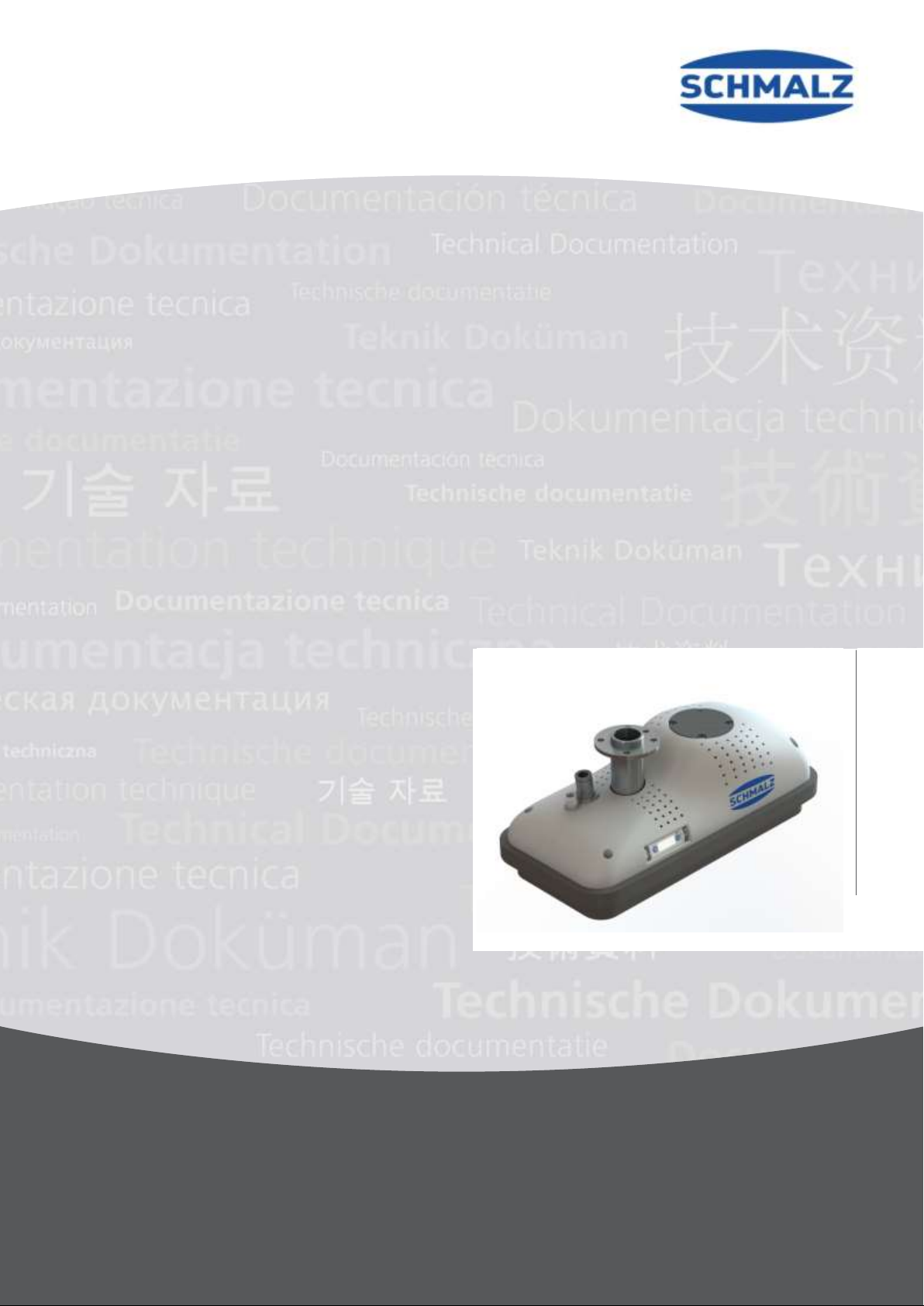
Vacuum Area Gripping System FXCB/FMCB
30.30.01.01840/01 | 03.2019
Innovative Vacuum for Automation
www.schmalz.com
Page 2

Note
These operating instructions were originally written in German and have been translated into English.
Store in a safe place for future reference.
Subject to technical changes without notice. No responsibility is taken for printing or other types of
errors.
Published by
© J. Schmalz GmbH, 03.2019
This document is protected by copyright. J. Schmalz GmbH retains the rights established thereby.
Reproduction of the contents, in full or in part, is only permitted within the limits of the legal provisions
of copyright law. Any modifications to or abridgments of the document are prohibited without explicit
written agreement from J. Schmalz GmbH.
Contact
J. Schmalz GmbH
Johannes-Schmalz-Str. 1
72293 Glatten, Germany
Tel. +49 (0) 7443 2403-0
Fax +49 (0) 7443 2403-259
[email protected]
www.schmalz.com
Contact information for Schmalz companies and trade partners worldwide can be found at
www.schmalz.com/salesnetwork
www.schmalz.com
Page 3

Contents
Vacuum Area Gripping System FXCB/FMCB
1 Safety Instructions ............................................................................................... 5
Classification of Safety Instructions .................................................................................. 5 1.1
Prohibition Signs................................................................................................................ 6 1.2
Warnings ........................................................................................................................... 6 1.3
Mandatory Symbols ........................................................................................................... 6 1.4
General Safety Instructions ............................................................................................... 7 1.5
Intended Use ..................................................................................................................... 8 1.6
Note on the Type Plate ...................................................................................................... 9 1.7
2 Product Description ............................................................................................. 9
Functional Principle ........................................................................................................... 9 2.1
Design of the FXCB with Integrated Vacuum Generation ...............................................10 2.2
Design of the FMCB for External Vacuum Generation ...................................................11 2.3
3 Technical Data .................................................................................................. 12
4 Transport and Assembly ................................................................................... 16
Delivery ............................................................................................................................16 4.1
4.1.1 Items Included in Delivery ...............................................................................................16
4.1.2 Checking for Completeness ............................................................................................16
4.1.3 Reporting Damage ..........................................................................................................17
Packaging ........................................................................................................................17 4.2
Storage ............................................................................................................................17
4.3
5 Start of Operations and Setup ........................................................................... 18
Mechanical Connection ...................................................................................................21 5.1
Pneumatic Connection ....................................................................................................22 5.2
22
Vacuum Connection (only FMCB) ...................................................................................23 5.3
Electrical Connection .......................................................................................................24 5.4
6 Operation .......................................................................................................... 26
General Notes .................................................................................................................26 6.1
Handling Solution ............................................................................................................29 6.2
7 Troubleshooting ................................................................................................ 30
8 Maintenance...................................................................................................... 34
General Maintenance Instructions...................................................................................34 8.1
Maintenance Schedule ....................................................................................................35 8.2
External Vacuum Generator (only FMCB) ......................................................................36 8.3
Ejectors (only FXCB) .......................................................................................................36 8.4
Cleaning Agents ..............................................................................................................36 8.5
Sealing Plate ...................................................................................................................36 8.6
Opening the Gripper to Clean the Ejectors (only FXCB) ................................................37 8.7
Overview of the Tightening Torque of the Screws ..........................................................38 8.8
www.schmalz.com
Page 4

Mounting the Vacuum Switch in the Housing ..................................................................39 8.9
Checking the System for Leaks .......................................................................................39 8.10
9 Spare and Wearing Parts .................................................................................. 40
10 Accessories ....................................................................................................... 42
11 Pneumatic Circuit Diagram................................................................................ 44
Pneumatic Circuit Diagram FXCB ...................................................................................44 11.1
Pneumatic Circuit Diagram FMCB – Parallel Circuit .......................................................45 11.2
12 Other Applicable Documents............................................................................. 46
4 | EN www.schmalz.com 30.30.01.01840/01
Page 5
SAFETY INSTRUCTIONS
DANGER
Type and source of danger
Consequence
►
Remedial action
WARNING
Type and source of danger
Consequence
►
Remedial action
CAUTION
Type and source of danger
Consequence
►
Remedial action
ATTENTION
Type and source of danger
Consequence
►
Remedial action
Note/information
1 Safety Instructions
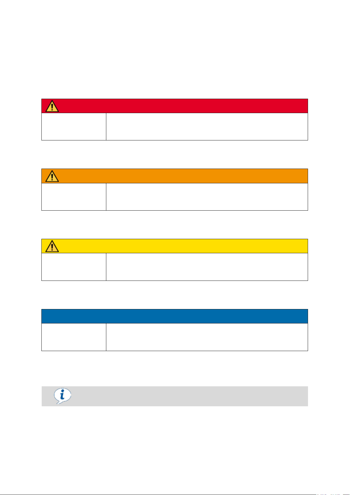
Classification of Safety Instructions 1.1
Danger
This warning informs the user of a risk that will result in death or serious injury if it is not avoided.
Warning
This warning informs the user of a risk that could result in death or serious injury if it is not avoided.
Caution
This warning informs the user of a risk that could result in injury if it is not avoided.
Attention
This warning informs the user of a risk that could result in damage to property if it is not avoided.
General notes
This symbol is used when important notes and information regarding the use of the machine/the system/the device are provided.
30.30.01.01840/01 www.schmalz.com EN | 5
Page 6
SAFETY INSTRUCTIONS
Icon
Description
Icon
Description
Do not stand under suspended loads
Icon
Description
Icon
Description
Pollution warning
Crushing injury
Suspended load
Hand injury warning
Electrical voltage
General warning symbol
Hearing damage
Warning of overpressure
Electric shock
Icon
Description
Icon
Description
Observe the instructions
Wear eye protection
Use protective footwear
Activate prior to maintenance or repair
Wear protective gloves
Wear a mask
Use ear protectors
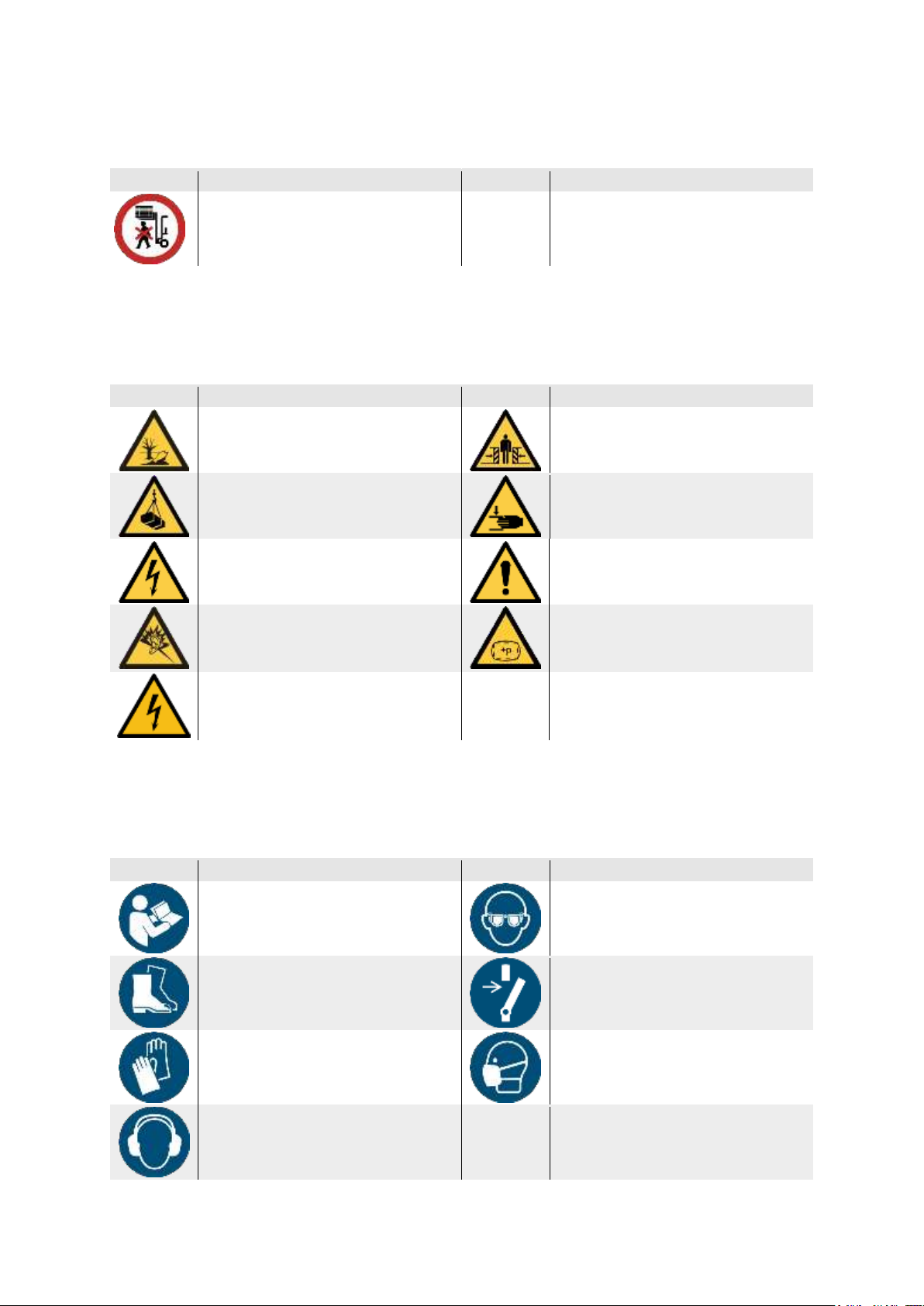
Prohibition Signs 1.2
Explanation of the prohibition signs used in the operating instructions.
Warnings 1.3
Explanation of the warning symbols used in the operating instructions.
Mandatory Symbols 1.4
Explanation of the mandatory symbols used in the operating instructions.
6 | EN www.schmalz.com 30.30.01.01840/01
Page 7
SAFETY INSTRUCTIONS
WARNING
Failure to comply with the general safety instructions
Personal injuries and damage to the system
►
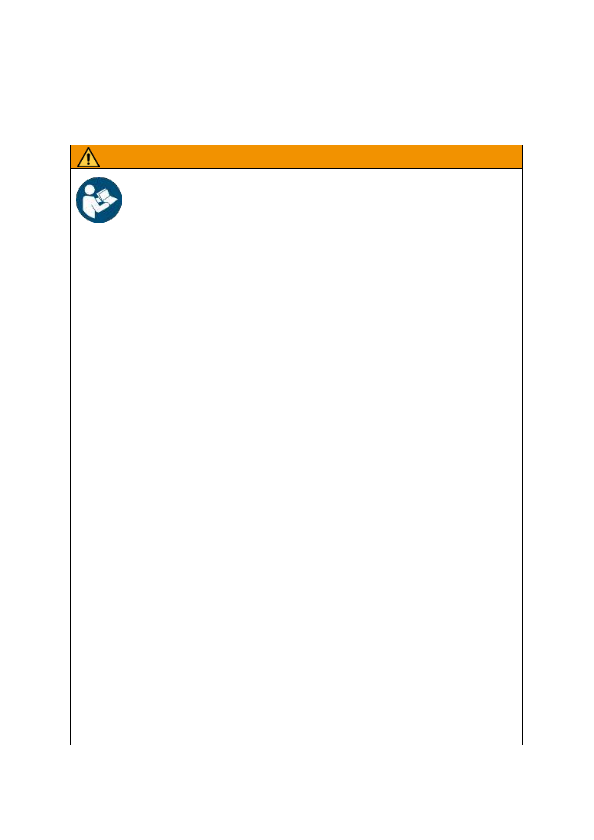
The operating instructions contain important information on using the system.
Read the operating instructions thoroughly and keep them for later reference.
►
The system must only be used by trained personnel who have read and understood the operating instructions.
►
These operating instructions are specific to the items included in delivery from
Schmalz. These operating instructions do not take into account any modifications to the system made by the customer.
►
The system may only be connected and operations started once the operating
instructions have been read and understood.
►
Use only the connections, mounting holes and attachment materials that have
been provided.
►
Carry out mounting or removal only when the device is in a voltage-free and
depressurized state.
►
Only qualified specialist personnel, mechanics and electricians may perform
the installation. Qualified specialist personnel are persons who have received
technical training and have the knowledge and experience – including
knowledge of applicable regulations – necessary to enable them to recognize
possible dangers and implement the appropriate safety measures while per-
►
General safety regulations, European standards and VDE guidelines must be
observed and complied with.
►
The gripper is to be used in combination with an automated handling system
(gantry/robot). For this reason, you must also follow the safety regulations of
the corresponding system.
►
Animals are not permitted to sit or stand in the transport area.
►
Transporting persons or animals is prohibited!
►
Collaborative operation of the gripper is solely permitted with systems designed
for this purpose. The system integrator must ensure that the integrated safety
functions are working properly.
►
It is not permitted to make changes to system components.
►
The system may only be operated with the operating voltages specified for the
corresponding components.
►
Make sure that the workplace and surroundings are kept clean.
►
Protect the components from damage of any kind.
General Safety Instructions 1.5
The system is state-of-the-art and operationally reliable. However, dangers may arise.
30.30.01.01840/01 www.schmalz.com EN | 7
Page 8
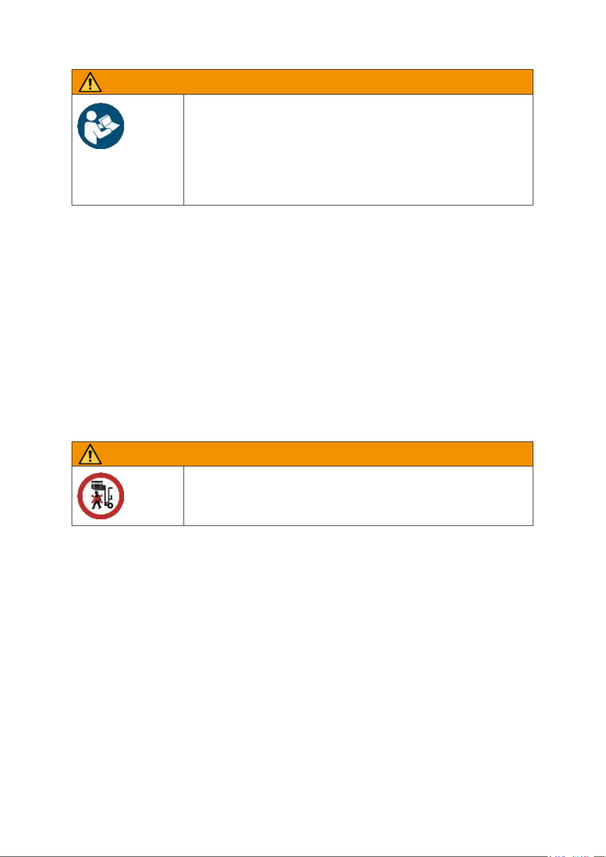
SAFETY INSTRUCTIONS
WARNING
Failure to comply with the general safety instructions
Personal injuries and damage to the system
►
Compressed air or a vacuum could cause closed containers to explode or
implode. Check the products before use.
►
Do not apply suction to any dangerous dusts, oil mists, vapors, aerosols, etc.
►
Only use suitable and approved vacuum filters.
►
Do not look into the exhaust air flow of the vacuum generator.
WARNING
Suspended loads
Personal injuries and damage to the system
►
Never stand under suspended loads.
Intended Use 1.6
The gripper is used to lift and transport cardboard boxes or similar materials that allow suction. Neutral
gases in accordance with EN 983 are approved as evacuation media. Neutral gases include air, nitrogen and inert gases.
The device may only be used with robot systems that comply with the provisions of DIN IST/TS 15066,
DIN EN ISO 10218-1 and DIN EN ISO 10218-2.
Operation as part of a collaborative system is only permitted when the entire system meets the corresponding legal requirements for collaborative robot systems. The system integrator is responsible for
ensuring that these requirements are complied with.
The possibilities to do this include:
- The use of redundant vacuum/compressed air generation
- The use of battery-operated audio-visual warning devices to monitor the input pressure and
vacuum value
- Safety-oriented vacuum generation and monitoring with a corresponding performance level
The system is mounted on the load suspension provided by the customer using the flanges designated for this purpose. The customer also provides a control device.
8 | EN www.schmalz.com 30.30.01.01840/01
Page 9

PRODUCT DESCRIPTION
When being applied to the workpiece, the foam must be compressed by at least
50%.
Note on the Type Plate 1.7
The type plate contains important information about the device. The type plate is firmly attached to the
exterior of the device.
The type plate contains the following information:
- Name
- Part number
- Production date
- Serial number
The designation and part number are important for identifying the device. They must always be specified when ordering replacement parts, making warranty claims or making other inquiries about the
device.
2 Product Description
Functional Principle 2.1
The system uses vacuum to lift the defined products. The system can be used to lift one or more
cardboard boxes or similar workpieces of various sizes without adapting the suction area to the specific workpiece.
The system achieves its maximum load-bearing capacity when the complete suction area is engaged
with an airtight workpiece with a smooth surface.
The robot system, to which the customer’s system was attached, is responsible for the motion in the
various axes.
30.30.01.01840/01 www.schmalz.com EN | 9
Page 10
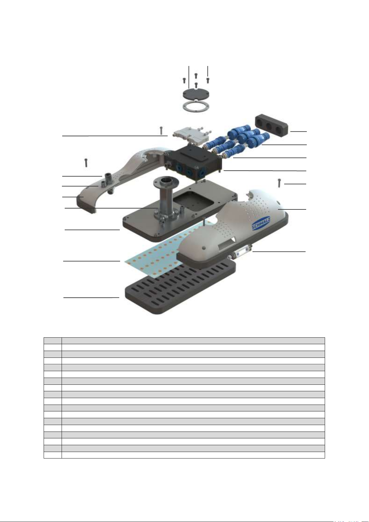
PRODUCT DESCRIPTION
Item
Description
A
Housing cover
B
Machine screw M4x10
C
Silencer
D
Valve
E
Retaining cap SHC
F
Ejector module SEP
G
Ejector block
H
Pneumatic interface Ø 10 mm
I
Machine screw M4x20
J
Electrical interface M12 8-pole
K
Housing right
L
Flange module
M
Housing left
N
Suction trough
O
Vacuum switch VSi
P
Masking film
Q
Sealing plate
A
C
E
G
F
M
I
Q
D
L B H
J
K O P
N
Design of the FXCB with Integrated Vacuum Generation 2.2
10 | EN www.schmalz.com 30.30.01.01840/01
Page 11
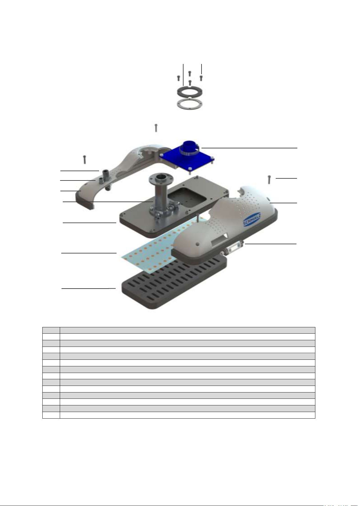
PRODUCT DESCRIPTION
Item
Description
A
Housing cover
B
Machine screw M4x10
C
Hose connector
D
Pneumatic interface Ø 10 mm
E
Machine screw M4x20
F
Electrical interface M12 8-pole
G
Housing right
H
Flange module
I
Housing left
J
Suction trough
K
Vacuum switch VSi
L
Masking film
M
Sealing plate
A
C
I
E M H B D
F
G K L
J
Design of the FMCB for External Vacuum Generation 2.3
30.30.01.01840/01 www.schmalz.com EN | 11
Page 12
TECHNICAL DATA
ATTENTION
Non adherence to the performance limits of the gripper
Malfunction and damage to the gripper and the attached
components.
►
Only operate the gripper within the specified performance limits
FXCB
With integrated vacuum generation
FMCB
For external vacuum generation
Number of suction cells
45
45
Optimal input pressure
5.5 bar1
-
Permitted pressure range
4.5 to 7.0 bar
Max. 7.0 bar2
Maximum degree of evacuation
53%4
90%4
Compressed air consumption
161.5 l/min4
-
Suction flow
525.9 l/min
-
Required suction flow rate
-
372.3 l/min
3.4
Permissible load
80 N
80 N
Weight
1.9 kg
1.5 kg
Operating voltage
24V DC
24V DC
Permitted temperature range
+5 to +40° C
+5 to +40° C
Sound level at full coverage
67.5 dB(A)4
-
Protection class
IP40
IP40
NFC tags in the gripper
Two NFC tags are integrated into the gripper. The first is located under the type
plate and links to the gripper page in the Schmalz app. The second is located in the
vacuum switch and links to the vacuum switch page.
To use the tags, hold an NFC-enabled device over the place where the NFC logo is
attached.
The linked pages contain data, part numbers and the operating instructions for the
respective parts.
Vacuum in the gripper
For workpieces typical for the application (e.g. cardboard boxes), a vacuum between 250 and 300 mbar is recommended.
A vacuum lower than 200 mbar is not recommended.
The overpressure in the gripper must be limited to a maximum of 0.2 bar.
Consult the manufacturer before operating it at higher or lower ambient temperatures.
3 Technical Data
1
At this pressure, the integrated ejectors have optimal energy efficiency.
2
For this gripper version, the compressed air is only used to more quickly deposit loads.
3
At a vacuum of –0.15 bar, the vacuum generator must provide the
specified suction flow rate (at the vacuum connection pieces of the FMCB).
4
Attention: this refers to real measured values without additional safety
12 | EN www.schmalz.com 30.30.01.01840/01
Page 13

TECHNICAL DATA
30.30.01.01840/01 www.schmalz.com EN | 13
Page 14
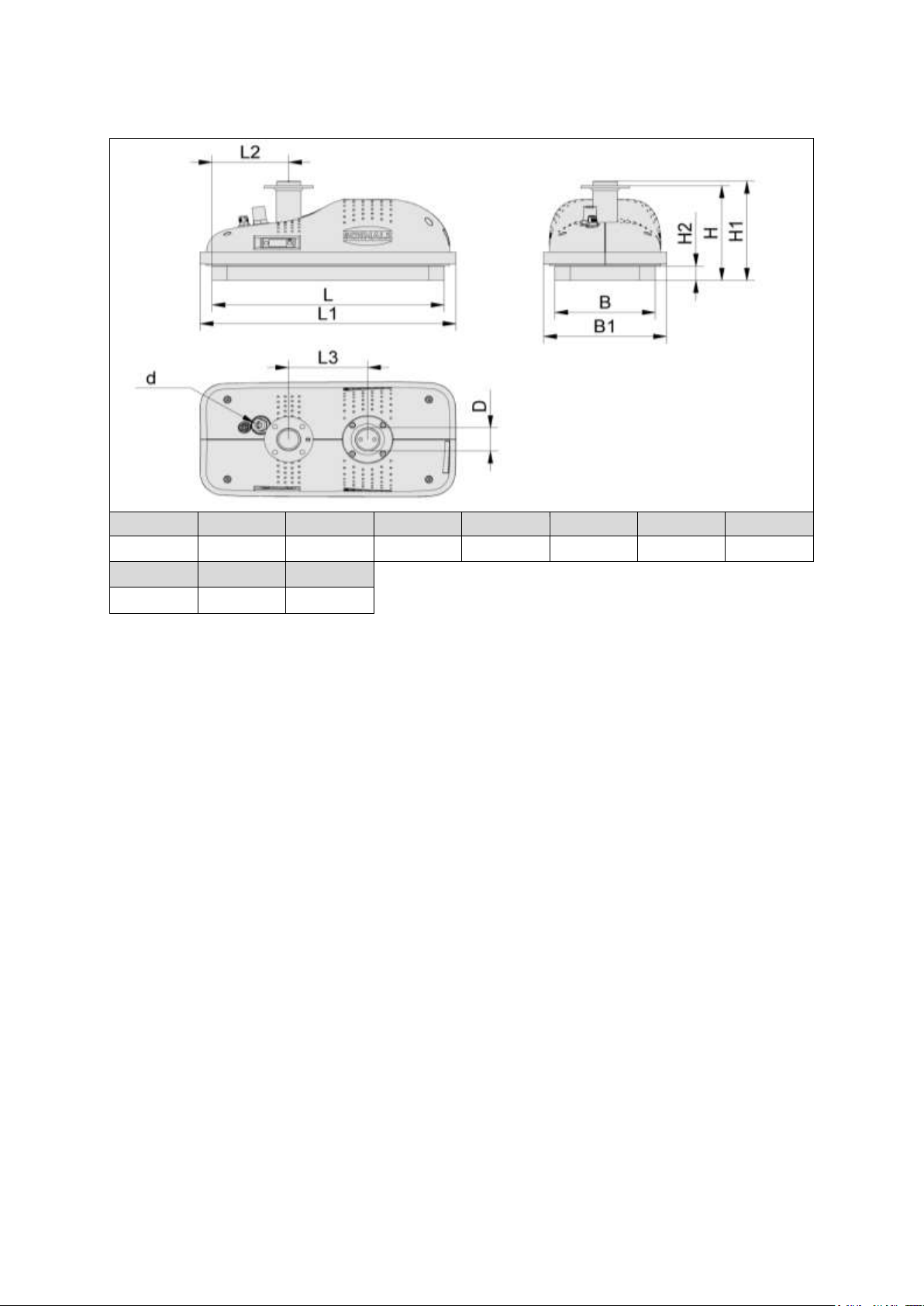
TECHNICAL DATA
L
B H
L11
L2
L3
B11
H1
300
130
131.4
331
99
102
159
137.4
H2 d D2
20
10
32
Dimensions:
1
Exact dimensions vary based on the circumferential foam
2
Only for the FMCB
14 | EN www.schmalz.com 30.30.01.01840/01
Page 15
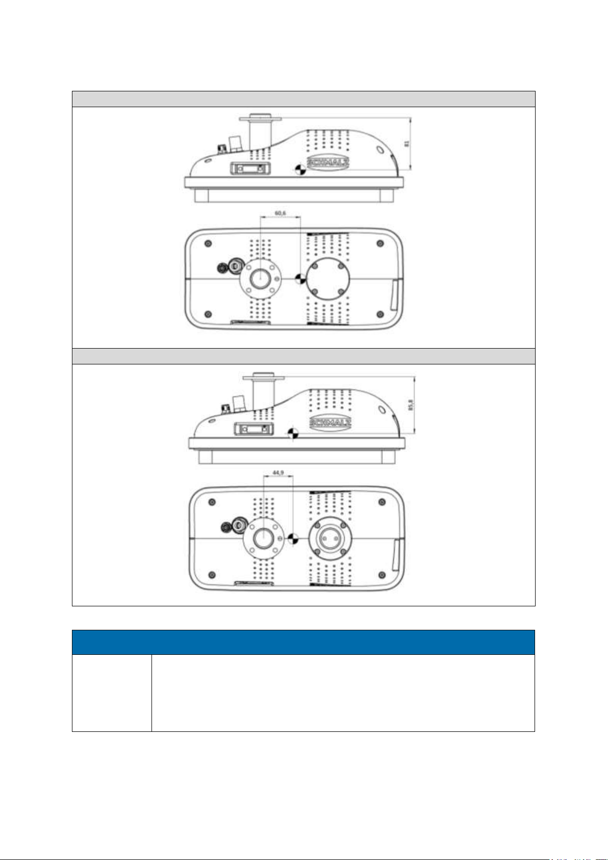
TECHNICAL DATA
FXCB
FMCB
ATTENTION
Using vacuum hoses that are too rigid with cobots (FMCB only)
Stopping the robot by interpreting the resistance of the hose as a collision with the
person
►
Before operation, check whether the resistance force of the vacuum hose causes the
robot to stop
Center of mass
30.30.01.01840/01 www.schmalz.com EN | 15
Page 16
TRANSPORT AND ASSEMBLY
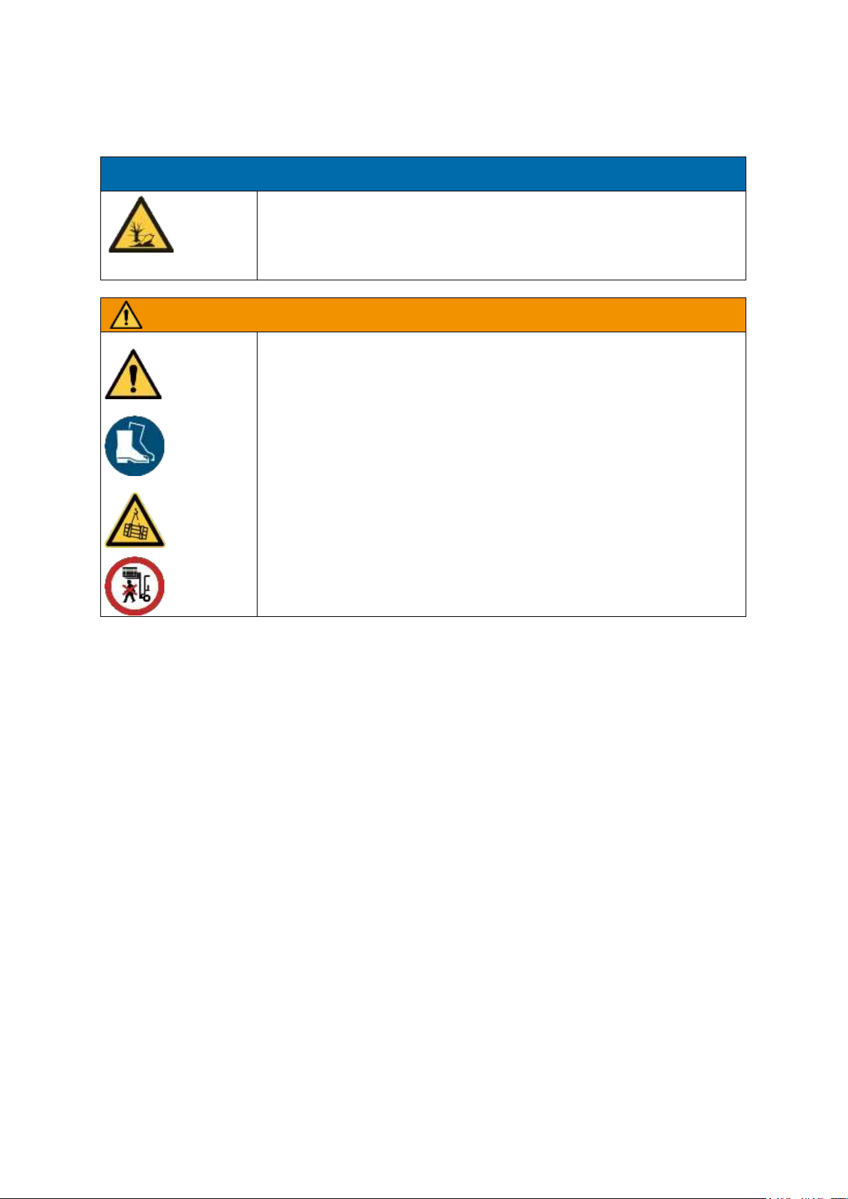
WARNING
Improper securing of the load
Improper unloading and transport can result in personal injuries and damage to
property. Moving loads can tip over, fall or crush people. When lifting transport
units, parts can fall over, move or fall out. Danger to life and limb.
►
Only transport loads that are sufficiently secured against slipping.
►
Ensure that all persons leave the hoist danger zone before the transport units
are lifted.
►
Wear protective footwear and additional safety equipment if necessary.
►
Only trained personnel who have received safety instructions may unload and
transport the product.
ATTENTION
Incorrect disposal of the system or individual components
Environmental damage
►
Disposal according to national guidelines.
4 Transport and Assembly
Delivery 4.1
4.1.1 Items Included in Delivery
For the exact items included in delivery, please refer to the order confirmation.
In addition to the gripper, the following is included in delivery:
4 pcs. M6x12 machine screw according to DIN 7984 for mounting the gripper on the robot
4 pcs. Safety washers to secure against accidental release of the gripper during operation
1 pc Dowel pin Ø 6 mm for exact position locking
1 pc Allen key, size 4, for tightening the screws
1 pc Quick Reference Guide
1 pc Electrical connection cable for connecting the gripping system to the robot (optional)
1 pc Hose clamp (only for FMCB)
Note
The operating instructions are part of the system and must be kept with the system every time it is
relocated.
4.1.2 Checking for Completeness
Using the enclosed delivery documents, check the entire shipment to ensure that it is complete. Also
refer to our Terms and Conditions of Sale and Delivery.
16 | EN www.schmalz.com 30.30.01.01840/01
Page 17

TRANSPORT AND ASSEMBLY
ATTENTION
Incorrect storage of the system
Material damage to the system
►
The system may only be stored as described in the operating instructions.
4.1.3 Reporting Damage
After delivery of the shipment, damage due to faulty packaging or transport must be reported immediately to the carrier and J.Schmalz GmbH.
Packaging 4.2
The system is shipped in a transport box made specifically for the system.
Storage 4.3
The system must be stored in its original packaging as long as it is not being used and is to be stored
for any period of time.
30.30.01.01840/01 www.schmalz.com EN | 17
Page 18
START OF OPERATIONS AND SETUP
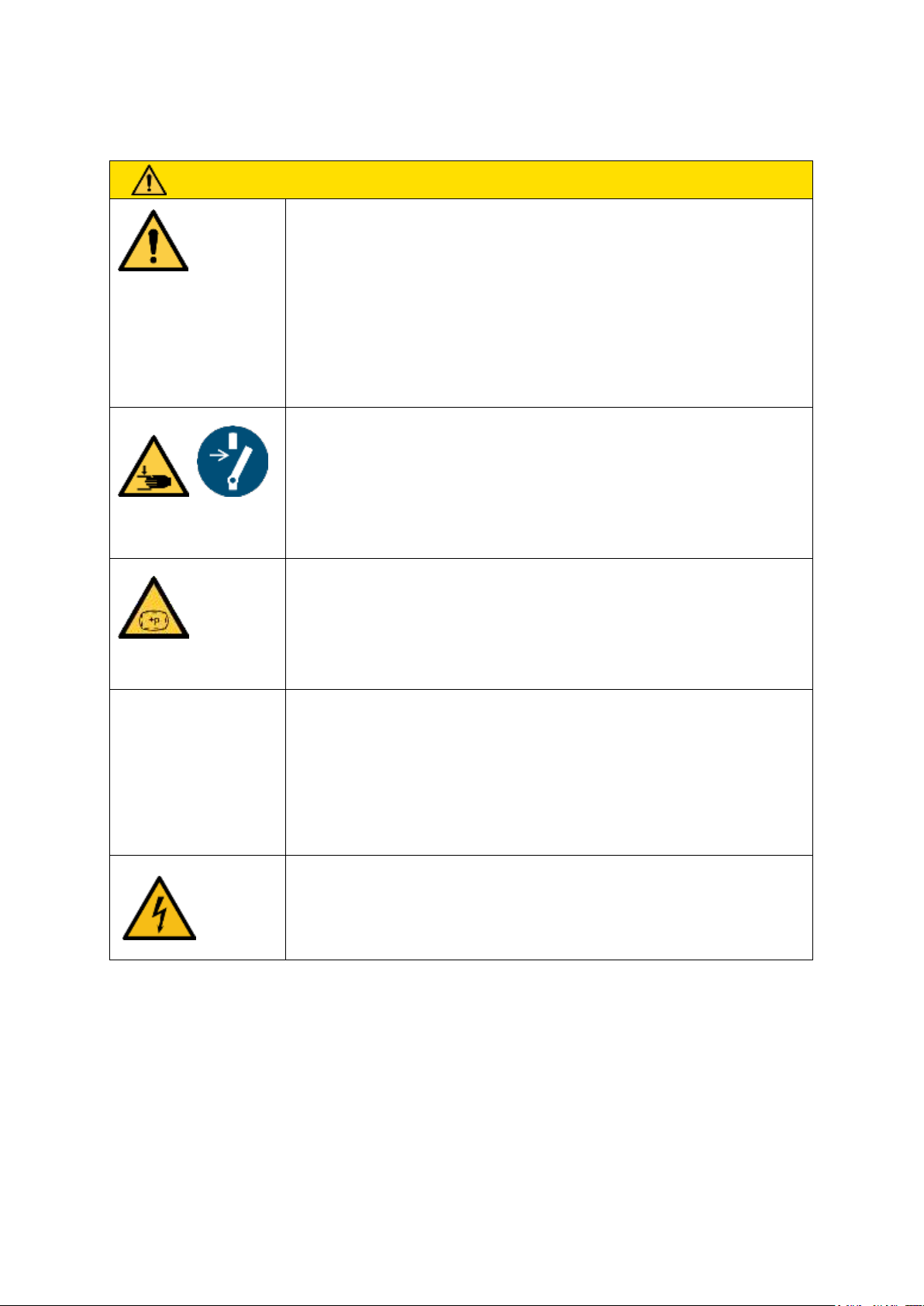
CAUTION
General notes on the start of operations
Risk of injuries
►
The system integrator must secure the danger zone.
►
The production system must be stopped in the area where the system is
being set up.
►
The system may only be set up at the workplace in accordance with the
operating instructions.
►
The system must be disconnected and depressurized during setup.
►
The production system must be secured to prevent activation during
setup.
Approach of a moving element to a fixed part/machinery mobility/moving elements
Body parts could be crushed, sucked in or caught if the flat suction cup
is abruptly attached to a workpiece or a surface.
►
Do not place any body parts between the bottom of the gripper and a
surface.
High pressure
Placement/release of compressed air lines
►
The system integrator must secure the danger zone.
►
Regularly inspect the gripper and perform regular maintenance in order
to detect and replace porous compressed air lines in good time. Replace defective connectors.
Stored energy/vacuum
Body parts could be crushed, cut, sucked in, caught or sliced if the flat
suction cup is abruptly attached to a workpiece or a surface.
►
Do not place any body parts between the bottom of the gripper and a
surface.
►
Eyes can be sucked in; do not look into open vacuum openings.
Conductive parts/parts that have become live in an error
state/short circuits
Electric shock
►
Regularly inspect and perform maintenance on the gripper to detect and
repair wear or faulty connections in good time.
5 Start of Operations and Setup
18 | EN www.schmalz.com 30.30.01.01840/01
Page 19
START OF OPERATIONS AND SETUP
CAUTION
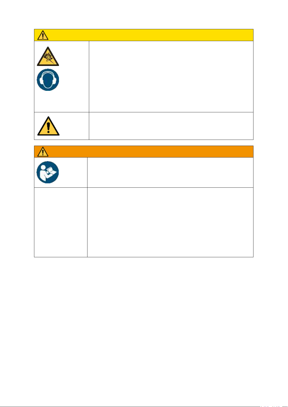
Noise hazards due to the exhaust system or gas flowing at high
speeds or worn parts
Discomfort, tinnitus, stress, exhaustion due to constant/
high noise levels
►
If possible, switch off vacuum generators (only FMCB) and the blow-off
function when not in use in order to reduce noise pollution.
►
Wear personal protective equipment e.g. ear protectors
►
If possible, position vacuum generators (only FMCB) far enough away
from machine operators; use additional silencers
►
Regularly inspect and perform maintenance on the system in order to
ensure that it works properly.
Careless use of personal protective equipment
Danger to the operator
►
Adapt and wear appropriate personal protective equipment based on
the task being performed.
WARNING
System setup by untrained personnel
Serious personal injury
►
The system must only be set up by trained personnel who have read and understood the operating instructions.
Non-compliance with work safety instructions
Personal injuries and damage to the system
►
Never lift loads at an angle and never drag them.
►
Do not tear off stuck loads.
►
Only pick up and lift suitable loads (check inherent stability and surface density).
►
Only set workpieces down on clear, even surfaces due to the danger of slipping.
►
Do not release the load until it rests completely and safely on a secure surface.
►
Do not come close to the load when releasing/depositing it and do not touch it.
30.30.01.01840/01 www.schmalz.com EN | 19
Page 20
START OF OPERATIONS AND SETUP
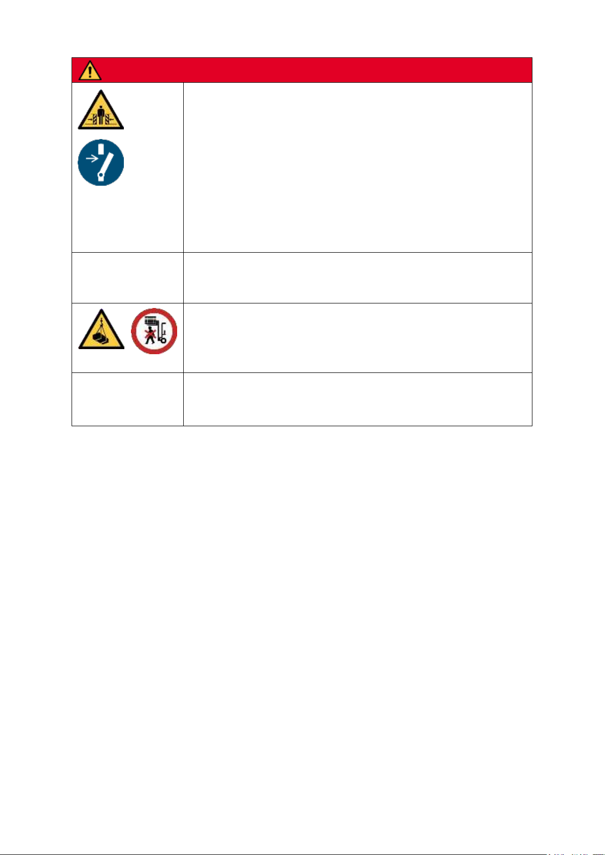
DANGER
General safety notes on the start of operations
Danger to life and limb
►
The system must only be set up by trained personnel who have read and understood the operating instructions.
►
The system integrator must secure the danger zone.
►
The production system must be stopped in the area where the system is being
set up
►
The system may only be set up at the workplace in accordance with the operating instructions.
►
The system must be disconnected during setup.
►
The production system must be secured to prevent activation during setup.
Acceleration/deceleration/kinetic energy
Danger to life and limb
►
See general safety notes on the start of operations
Danger of falling objects/gravity:
Danger to life and limb
►
See general safety notes on the start of operations
►
Never stand under suspended loads.
Human error
Danger to life and limb
►
Adhere to the operating instructions
20 | EN www.schmalz.com 30.30.01.01840/01
Page 21
START OF OPERATIONS AND SETUP
Alternative flange images
Alternative flange images are available on request.
Mechanical Connection 5.1
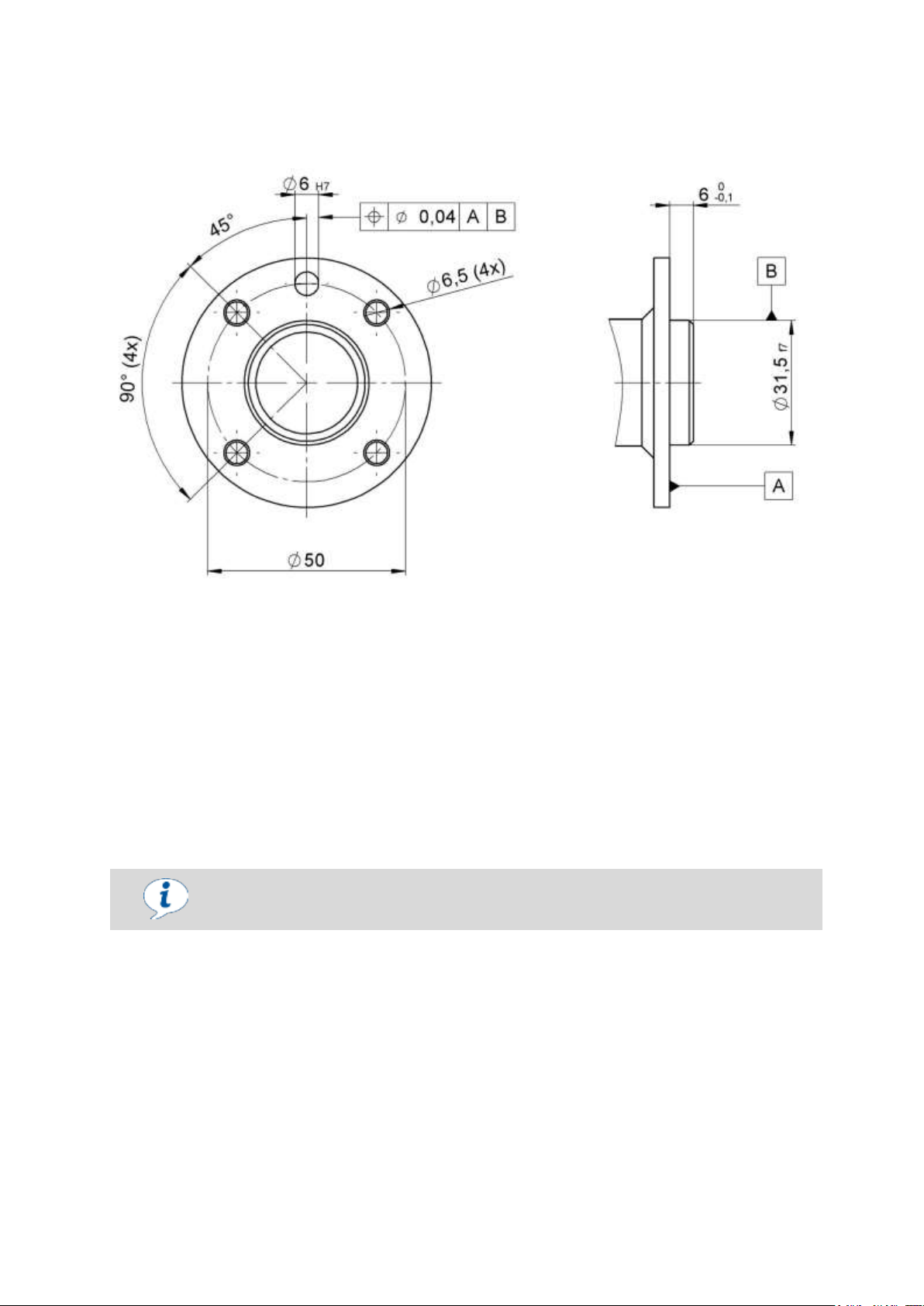
The system is equipped with a flange connection in accordance with ISO 9409-1-50-4-M6:
The gripper initially comes equipped with a Ø31.5 f7 base in the corresponding robot flange adapter in
order to mount the gripper onto the robot/system.
Afterwards, the position of the gripper can be precisely determined using the included dowel pin if
desired. To do so, position the Ø6H7 bore hole of the gripper flange so that it is congruent with the
Ø6H7 bore hole of the robot flange. Then fix the position by inserting the dowel pin.
Use the included screws and safety washers to mount the gripper on the robot. The required tightening torque can be found in the operating instructions of the robot system.
The system must be attached securely, taking the weight of the system and its maximum load-bearing
capacity into account.
30.30.01.01840/01 www.schmalz.com EN | 21
Page 22
START OF OPERATIONS AND SETUP
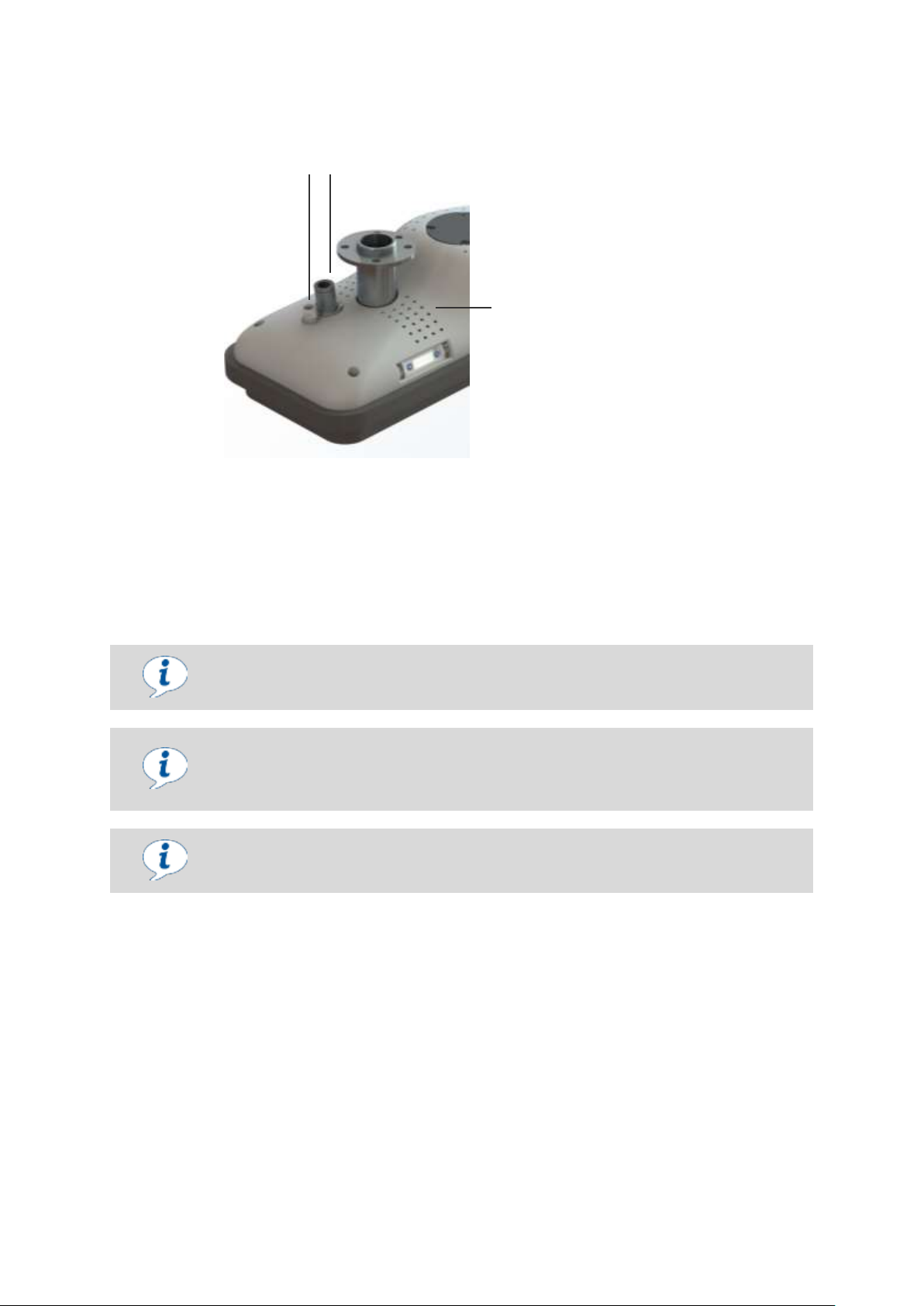
1 23
1. Electrical connection
2. Pneumatic connection
3. Blow-off opening
Maximum overpressure
The maximum overpressure in the gripper must be limited to a maximum of 0.2 bar.
Ventilation
The openings along the housing of the gripper serve as outlets for the exhaust air
from the ejectors (only FXCB). In order to maintain the gripper’s functionality, these
openings may not be closed or covered.
Alternative hose connections
Plug-in screw unions for alternative hose sizes as well as corresponding compressed air hoses are available on request.
Pneumatic Connection 5.2
The compressed air is connected using the plug-in screw union for compressed air hoses, which is
located on the sealing plate and is included in delivery. Requirements for the compressed air provided
by the customer:
Dry, filtered air according to ISO 8573-1:2010 [7:4:4]
Constant operating pressure: 5.5 bar.
If you select a supply hose that is too small, the compressed air supplied to the pneumatic elements
will not be enough for optimal operation.
22 | EN www.schmalz.com 30.30.01.01840/01
Page 23
START OF OPERATIONS AND SETUP
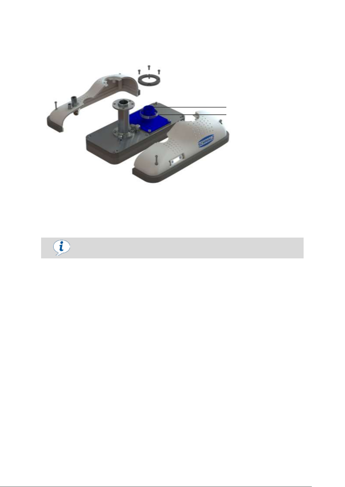
1. Hose connection
2. Hose clamp
Vacuum
Once vacuum is applied in a gripper, it immediately begins suction.
2
1
Vacuum Connection (only FMCB) 5.3
A hose that is suitable for vacuum applications must be connected at the installed hose connection
and secured with the included hose clamps. The supply hose must have the same nominal diameter
as the installed connection. The maximum recommended hose length is around 10 meters.
For instructions on opening the housing, see chapter 8.7.
30.30.01.01840/01 www.schmalz.com EN | 23
Page 24
START OF OPERATIONS AND SETUP
DANGER
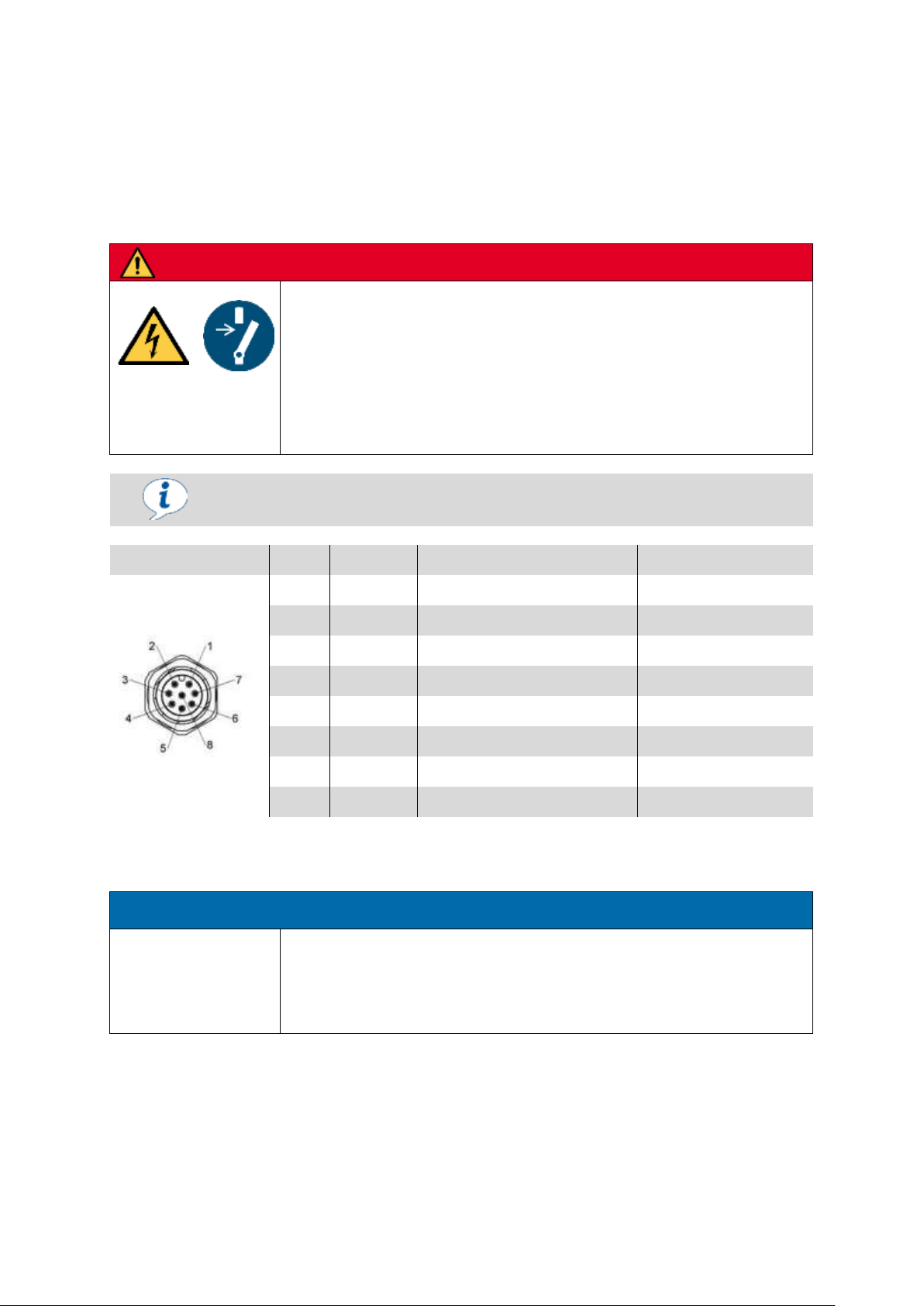
Inappropriate voltage supply
Electric shock, destruction of the electrical components
►
Connection work may only be carried out by a qualified electrical specialist.
►
The system must incorporate safe electrical cut-off of the power supply in compliance with EN60204
►
Do not connect or disconnect the plug connectors when voltage is applied.
►
Only operate the system with protected extra-low voltage.
Observe the corresponding operating instructions when connecting the external
vacuum generator (only FMCB).
Plug
Pin
Lead color
Function (PNP)
Function with IO-Link
1
White
Not used
2
Brown
24V DC power supply
31
Green
Valve mass
41
Yellow
“Suction OFF” signal input
2
5
Gray
Signal output 2
IO-Link communication
61
Pink
“Vent ON” signal input
7
Blue
Vacuum switch mass
8
Red
Signal output 1
ATTENTION
Incorrectly connected screw union
Malfunction
►
The multi-pole plug’s screw union must be sealed securely and correct-
ly during installation of the customer’s cable.
Electrical Connection 5.4
The connection for control of the solenoid valve (only FXCB) and the vacuum switch is made using an
8-pole M12 connector that is integrated into the housing.
The installed valve and the valve switch are switched via PNP.
The plug connectors must not be connected or disconnected when the system is live.
The power supply and signal inputs have a maximum line length of 30 meters.
1
These pins are only assigned for the FXCB version. These pins are not assigned for gripper FMCB.
2
The installed valve for suction is normally open. In the de-energized or disconnected
state, the gripper is in “Suction” mode.
24 | EN www.schmalz.com 30.30.01.01840/01
Page 25
START OF OPERATIONS AND SETUP
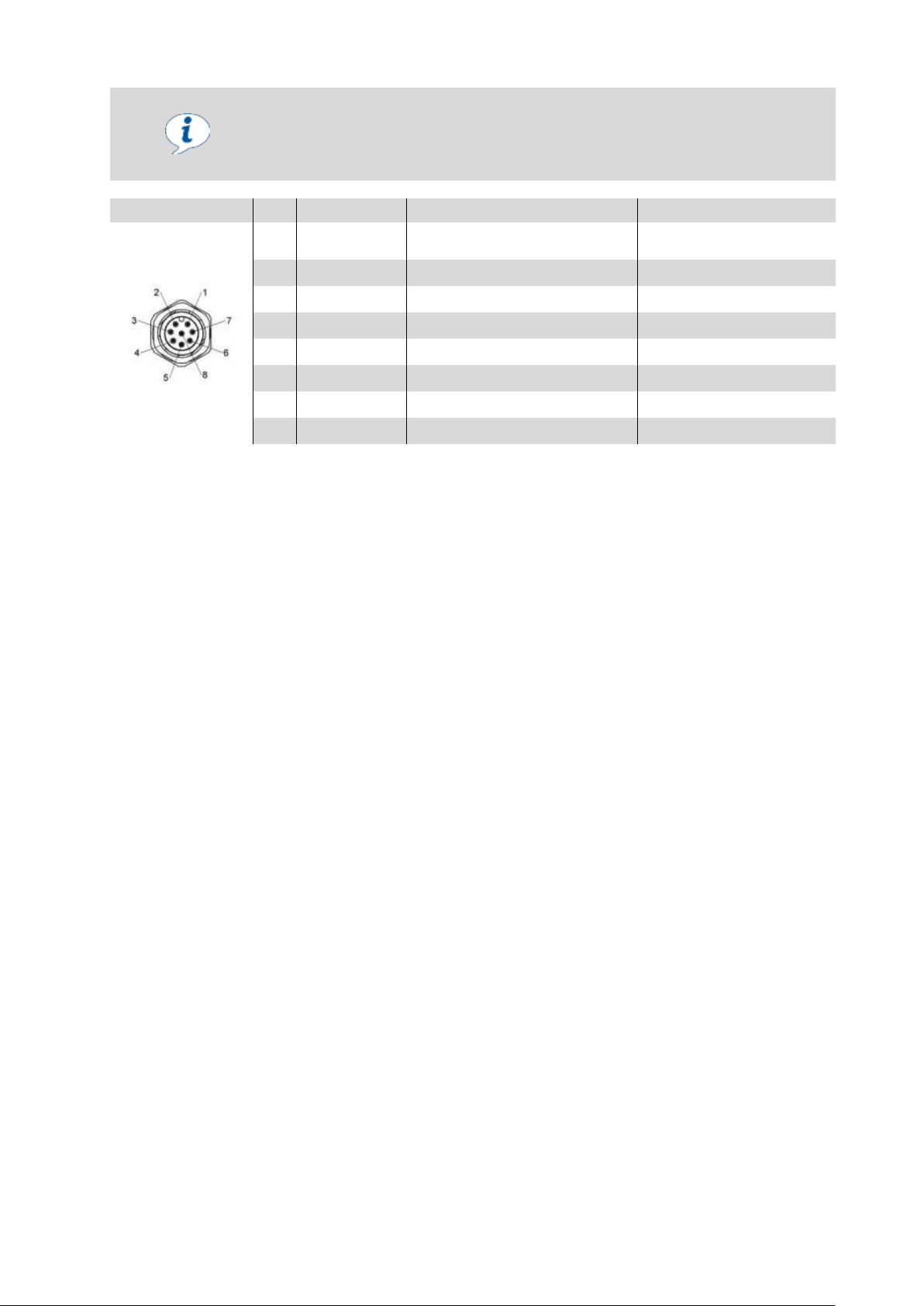
The grippers FXCB 10.01.43.00001 and FMCB 10.01.43.00002 are PNP-switched.
NPN-switched versions of these grippers are available upon request
(FXCB 10.01.43.00016 and FMCB 10.01.43.00017).
The NPN pin assignments are as follows:
Plug
Pin
Lead color
Function (PNP)
Function with IO-Link
1
White
24V DC Power supply of the
valve
2
Brown
24V DC power supply
3
Green
Not used
4
Yellow
"Suction OFF" signal input
5
Gray
Signal output 2
IO-Link communication
6
Pink
“Vent ON” signal input
7
Blue
Vacuum switch mass
8
Red
Signal output 1
30.30.01.01840/01 www.schmalz.com EN | 25
Page 26
OPERATION
CAUTION
General Notes on Operation
Risk of injuries
►
The system integrator must ensure that the entire system complies with the provisions of DIN IST/TS 15066, DIN EN ISO
10218-1 and DIN EN ISO 10218-2.
►
The system may only be operated at the workplace in accordance with
the operating instructions.
Approach of a moving element to a fixed part/machinery mobility/moving elements
Body parts could be crushed, sucked in or caught if the flat suction cup
is abruptly attached to a workpiece or a surface or by moving parts.
►
Do not place any body parts between the bottom of the gripper and a
surface.
High pressure
Placement/release of compressed air lines
►
The system integrator must secure the danger zone.
►
Regularly inspect the gripper and perform regular maintenance in order
to detect and replace porous compressed air lines in good time. Replace defective connectors.
Stored energy/vacuum
Body parts could be crushed, cut, sucked in, caught or sliced if the flat
suction cup is abruptly attached to a workpiece or a surface.
►
Do not place any body parts between the bottom of the gripper and a
surface.
►
Eyes can be sucked in; do not look into open vacuum openings.
Conductive parts/parts that have become live in an error
state/short circuits
Electric shock
►
Regularly inspect and perform maintenance on the gripper to detect and
repair wear or faulty connections in good time.
6 Operation
General Notes 6.1
26 | EN www.schmalz.com 30.30.01.01840/01
Page 27
OPERATION
CAUTION
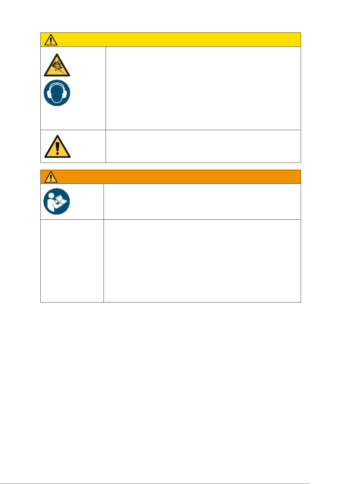
Noise hazards due to the exhaust system or gas flowing at high
speeds or worn parts
Discomfort, tinnitus, stress, exhaustion due to constant/
high noise levels
►
If possible, switch off vacuum generators (only FMCB) and the blow-off
function when not in use in order to reduce noise pollution.
►
Wear personal protective equipment e.g. ear protectors
►
If possible, position vacuum generators (only FMCB) far enough away
from machine operators; use additional silencers
►
Regularly inspect and perform maintenance on the system in order to
ensure that it works properly.
Careless use of personal protective equipment
Danger to the operator
►
Adapt and wear appropriate personal protective equipment based on
the task being performed.
WARNING
System operation by untrained personnel
Serious personal injury
►
The system may only be operated by trained personnel who have read and
understood the operating instructions.
Non-compliance with work safety instructions
Personal injuries and damage to the system
►
Never lift loads at an angle and never drag them.
►
Do not tear off stuck loads.
►
Only pick up and lift suitable loads (check inherent stability and surface density).
►
Only set workpieces down on clear, even surfaces
due to the danger of slipping.
►
Do not release the load until it rests completely and safely on a secure surface.
►
Do not come close to the load when releasing/depositing it and do not touch it.
30.30.01.01840/01 www.schmalz.com EN | 27
Page 28
OPERATION
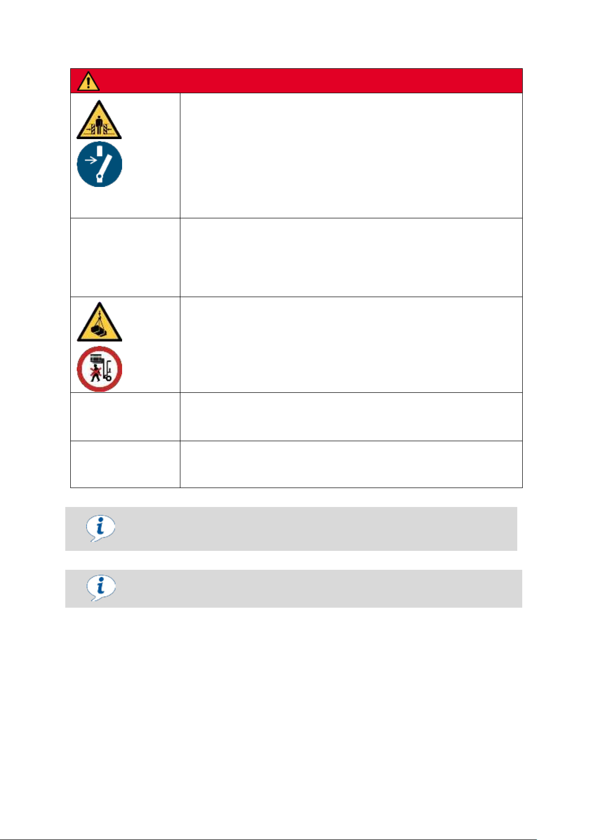
DANGER
General Safety Notes on Operation
Danger to life and limb
►
The system may only be operated by trained personnel who have read and
understood the operating instructions.
►
Operation in a collaborative system is only permitted when the entire system
complies with the corresponding requirements for collaborative robot systems
in accordance with DIN IST/TS 15066, DIN EN ISO 10218-1 and DIN EN ISO
10218-2.
►
The system may only be operated at the workplace in accordance with the
operating instructions.
Acceleration/deceleration/kinetic energy
Danger to life and limb due to workpieces slinging away
►
See general safety notes on the start of operations
►
Maintain sufficient distance to the moving system/workpiece in order to avoid
danger, even in the case of unforeseeable events (e.g. emergency stop)
Danger of falling objects/gravity due to falling objects
Danger to life and limb
►
See general safety notes on the start of operations
►
Never stand under suspended loads.
►
Do not place any body parts under the suspended load or the system.
►
The system’s maximum permitted load must not be exceeded.
Human error
Danger to life and limb
►
Adhere to the operating instructions
Switching components that are not explosion-proof
Risk of fire and explosion
►
The product must not be used in explosion risk areas.
Consult the manufacturer before operating it at ambient temperatures higher or
lower than the permitted temperatures.
For the maximum permitted load, see the technical data.
28 | EN www.schmalz.com 30.30.01.01840/01
Page 29
OPERATION
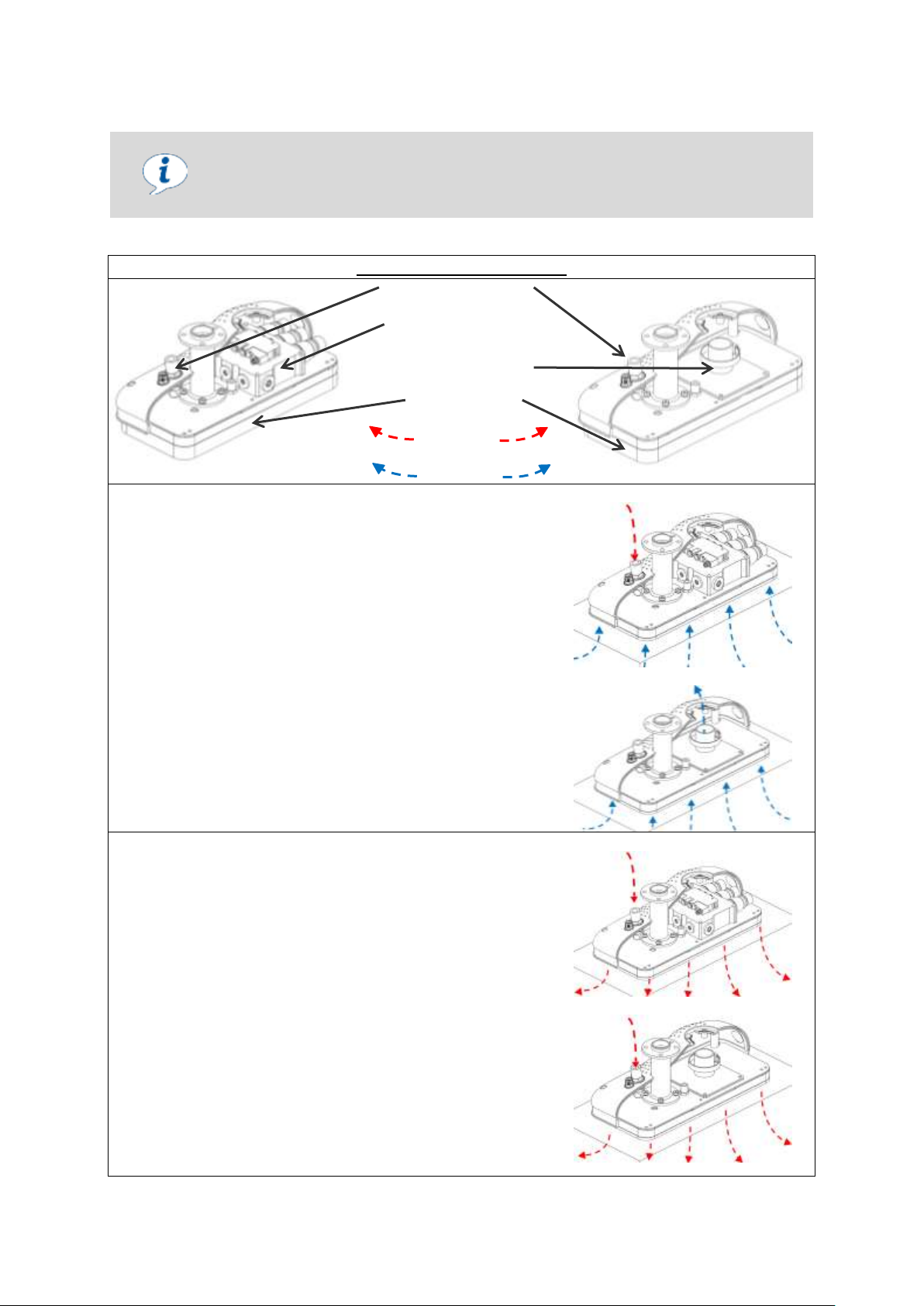
Optimized control
Only turn on the suction when workpieces are being lifted. Otherwise, additional
dust from the environment is drawn in, which could shorten the necessary maintenance intervals.
Simplified diagram of a gripper
FXCB Compressed air connection
Vacuum generation
Vacuum connection
Sealing plate
Compressed air
Vacuum
FMCB
Applying suction
The gripper is placed onto the workpiece being handled.
The sealing plate must be compressed by at least 50% to
ensure that the workpiece is securely gripped.
Only FXCB: The gripper is reset to the “Suction” state by
switching the “Suction OFF” pin (see chapter 5.4). In order
for this to occur, there must be compressed air at the
compressed air connection.
Only FMCB: Vacuum is generated externally and must
be present at the vacuum connection. An additional valve
for switching between “Suction ON” and “Suction OFF” is
required.
Once the pre-set vacuum value is reached (green light on
the vacuum switch is on and there is an output signal on
the “Signal output 2” pin – see attached operating instructions), the gripper may be moved.
FXCB
FMCB
Setting down
Once the workpiece has been transported and safely set
down on the target surface, it must be deposited.
Only FXCB: Switching on the “Suction OFF” pin ends suc-
tion operation. Optionally, compressed air can be blown into the suction chamber in order to more quickly deposit the
workpiece by switching on the “Vent ON” pin. In order for
this to occur, there must be compressed air at the compressed air connection.
Only FMCB: To deposit the workpiece, the vacuum must
be switched off or disconnected at the vacuum connection.
Optionally, compressed air can be blown into the suction
chamber via the compressed air connection in order to
more quickly deposit the workpiece.
Once the workpiece has been deposited, the gripper must
be returned to a neutral state (Suction OFF and Blow-off
OFF).
FXCB
FMCB
Handling Solution 6.2
30.30.01.01840/01 www.schmalz.com EN | 29
Page 30
TROUBLESHOOTING
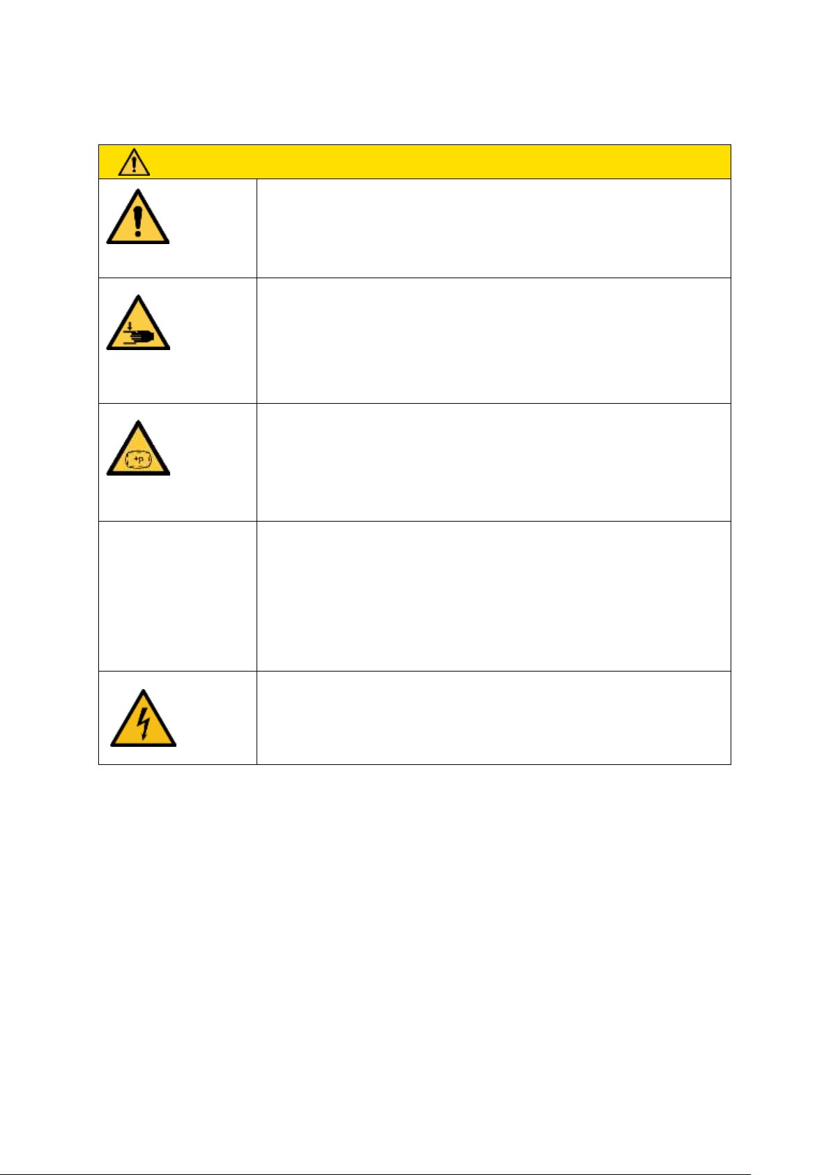
CAUTION
General notes on troubleshooting
Risk of injuries
►
The system integrator must secure the danger zone.
►
The system may only be operated at the workplace in accordance with
the operating instructions.
Approach of a moving element to a fixed part/machinery mobility/moving elements
Body parts could be crushed, sucked in or caught if the flat suction cup
is abruptly attached to a workpiece or a surface or by moving parts
►
Do not place any body parts between the bottom of the gripper and a
surface.
High pressure
Placement/release of compressed air lines
►
The system integrator must secure the danger zone.
►
Regularly inspect the gripper and perform regular maintenance in order
to detect and replace porous compressed air lines in good time. Replace defective connectors.
Stored energy/vacuum
Body parts could be crushed, cut, sucked in, caught or sliced if the flat
suction cup is abruptly attached to a workpiece or a surface.
►
Do not place any body parts between the bottom of the gripper and a
surface.
►
Eyes can be sucked in; do not look into open vacuum openings.
Conductive parts/parts that have become live in an error
state/short circuits
Electric shock
►
Regularly inspect and perform maintenance on the gripper to detect and
repair wear or faulty connections in good time.
7 Troubleshooting
30 | EN www.schmalz.com 30.30.01.01840/01
Page 31
TROUBLESHOOTING
CAUTION
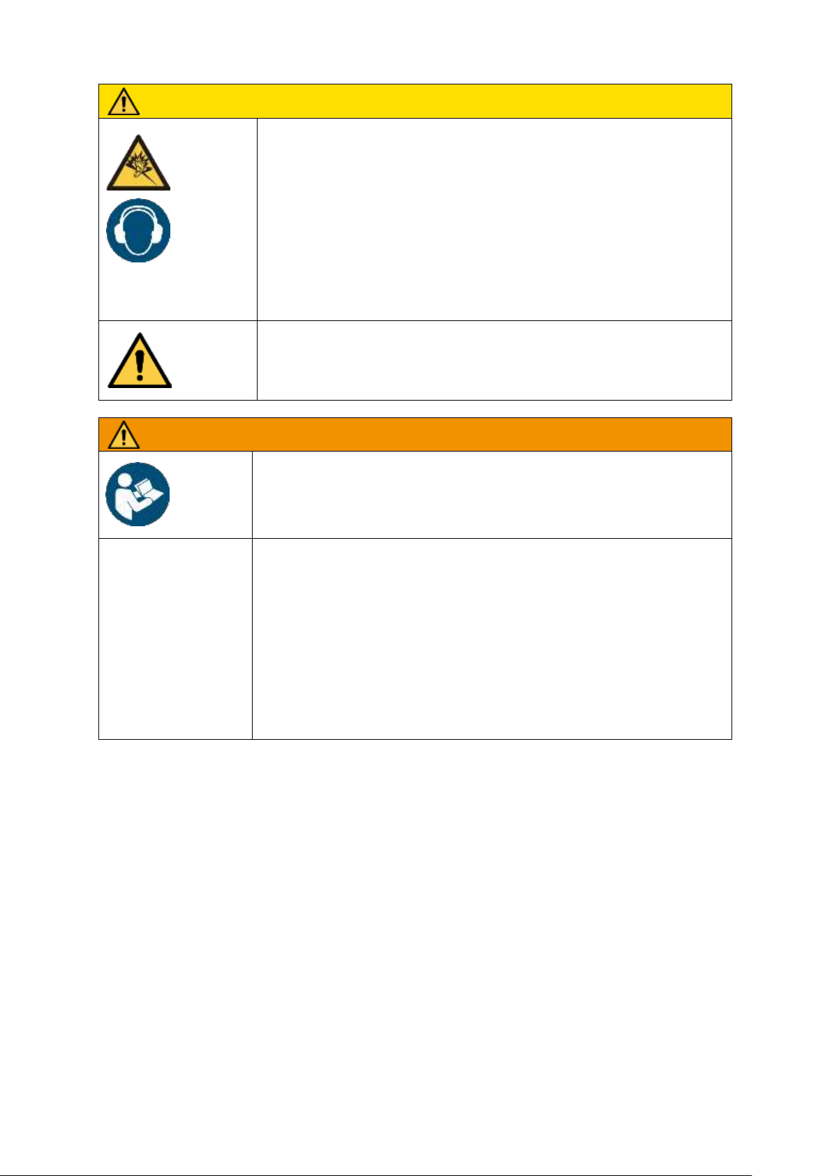
Noise hazards due to the exhaust system or gas flowing at high
speeds or worn parts
Discomfort, tinnitus, stress, exhaustion due to constant/
high noise levels
►
If possible, switch off vacuum generators and the blow-off function when
not in use in order to reduce noise pollution.
►
Wear personal protective equipment e.g. ear protectors
►
If possible, position vacuum generators far enough away from machine
operators; use additional silencers
►
Regularly inspect and perform maintenance on the system in order to
ensure that it works properly.
Careless use of personal protective equipment
Danger to the operator
►
Adapt and wear appropriate personal protective equipment based on
the task being performed.
WARNING
System operation by untrained personnel
Serious personal injury
►
The system may only be operated by trained personnel who have read and
understood the operating instructions.
Non-compliance with work safety instructions
Personal injuries and damage to the system
►
Never lift loads at an angle and never drag them.
►
Do not tear off stuck loads.
►
Only pick up and lift suitable loads (check inherent stability and surface density).
►
Only set workpieces down on clear, even surfaces due to the danger of slipping.
►
Do not release the load until it rests completely and safely on a secure surface.
►
Do not come close to the load when releasing/depositing it and do not touch it.
30.30.01.01840/01 www.schmalz.com EN | 31
Page 32
TROUBLESHOOTING
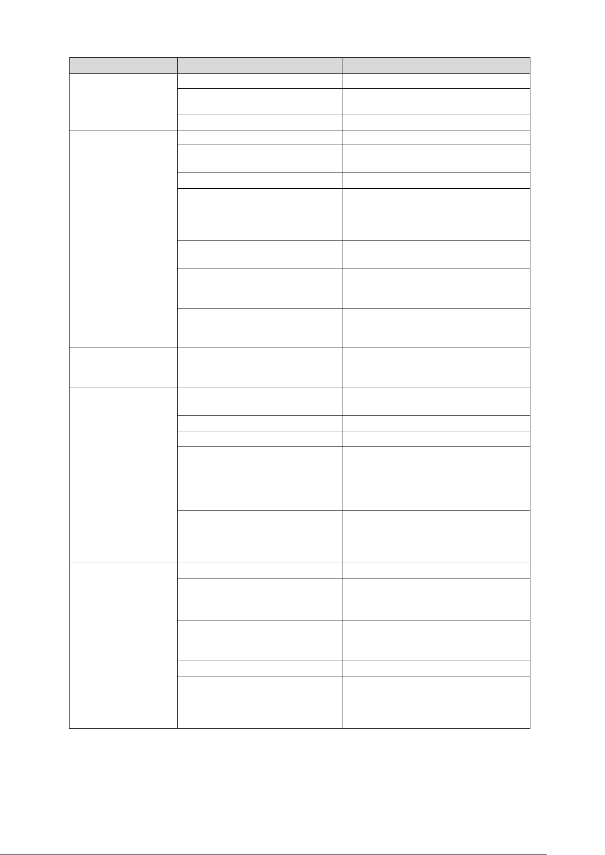
Error
Possible cause
Solution
Vacuum level is not
reach or vacuum is
created too slowly
Leakage in hose line
Check hose connections
Leakage or wear on the sealing
plates/sealing
Check the sealing plates/sealing and
replace if necessary
Ejectors are dirty (only FXCB)
Remove and clean ejectors
Load cannot be held
Vacuum level too low
See above for possible causes
Suction force not suitable for load
Increase vacuum or connect additional
grippers if necessary
Flow restrictors are dirty
Clean the masking film
The area gripper is not pressed
firmly enough onto the workpiece
to be lifted
Press the area gripper more firmly onto
the surface. On even surfaces, we recommend that the foam compress by at
least 50%.
Too short retention time for the
area gripper on the workpiece
Extend the retention time
Too fast or jerky lifting of workpieces
Optimize the motion. Avoid acceleration
peaks (especially when lifting the workpieces)
The workpieces to be lifted are not
suitable for the area grippers (e.g.
non-rigid).
Use a different gripping system.
Sealing plate wears
out very quickly
The area gripper is angled or
makes a grinding noise when applied to the workpiece to be lifted
Set it down vertically on the workpiece
Only FMCB:
External vacuum generator works, but
workpieces are not
picked up
If present: The dust filter of the
vacuum generator is dirty
Clean or replace dust filter
The sealing mat is damaged/torn
Replace sealing mat
Workpiece is too heavy
Workpiece is not suitable
Vacuum is too high
Determine the maximum possible vacuum of the vacuum generator; check the
system for leaks (hose connections,
sealing, etc.); valves are dirty; the workpiece is too porous
The sealing mat is not applied firmly enough
Press the area gripper more firmly onto
the surface. On even surfaces, we recommend that the foam compress by at
least around 50%.
Only FXCB:
Internal vacuum generator works, but
workpieces are not
picked up
The sealing mat is damaged/torn
Replace sealing mat
Workpiece is too heavy
Workpiece is not suitable
Input pressure is too low
Increase the input pressure. Check the
hoses for leakage. The workpiece is too
porous
The ejectors are dirty
Remove and clean ejectors
The sealing mat is not applied firmly enough
Press the area gripper more firmly onto
the surface. On even surfaces, we recommend that the foam compress by at
least around 50%.
32 | EN www.schmalz.com 30.30.01.01840/01
Page 33
TROUBLESHOOTING
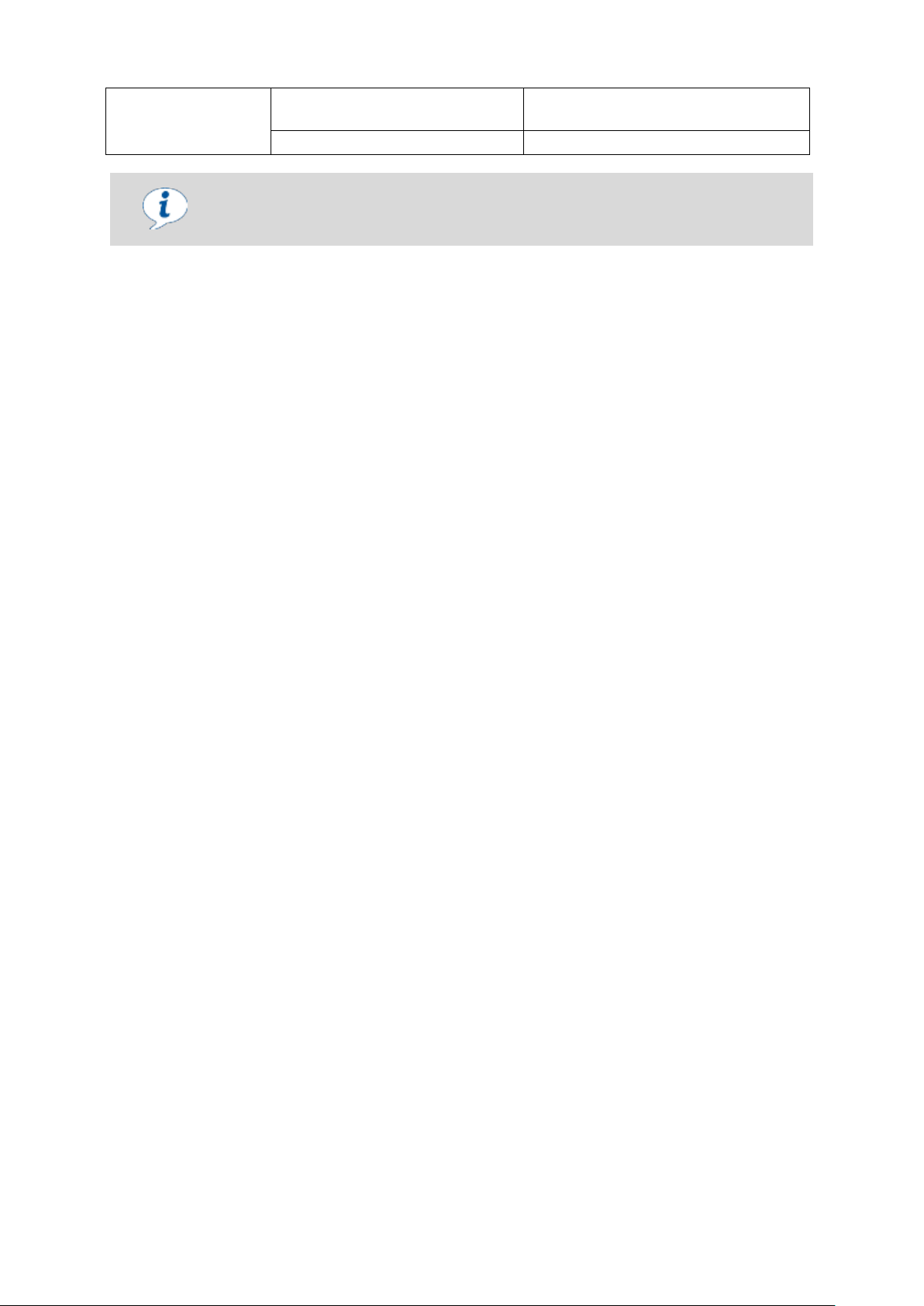
Solenoid valve is not
working
Electrical control is not working
Check the connections and replace
valve if necessary
Solenoid valve is defective
Repair or replace the solenoid valve
Recommendation
We recommend always performing tests with original sample workpieces. We would
be happy to help you with testing.
30.30.01.01840/01 www.schmalz.com EN | 33
Page 34
MAINTENANCE
CAUTION
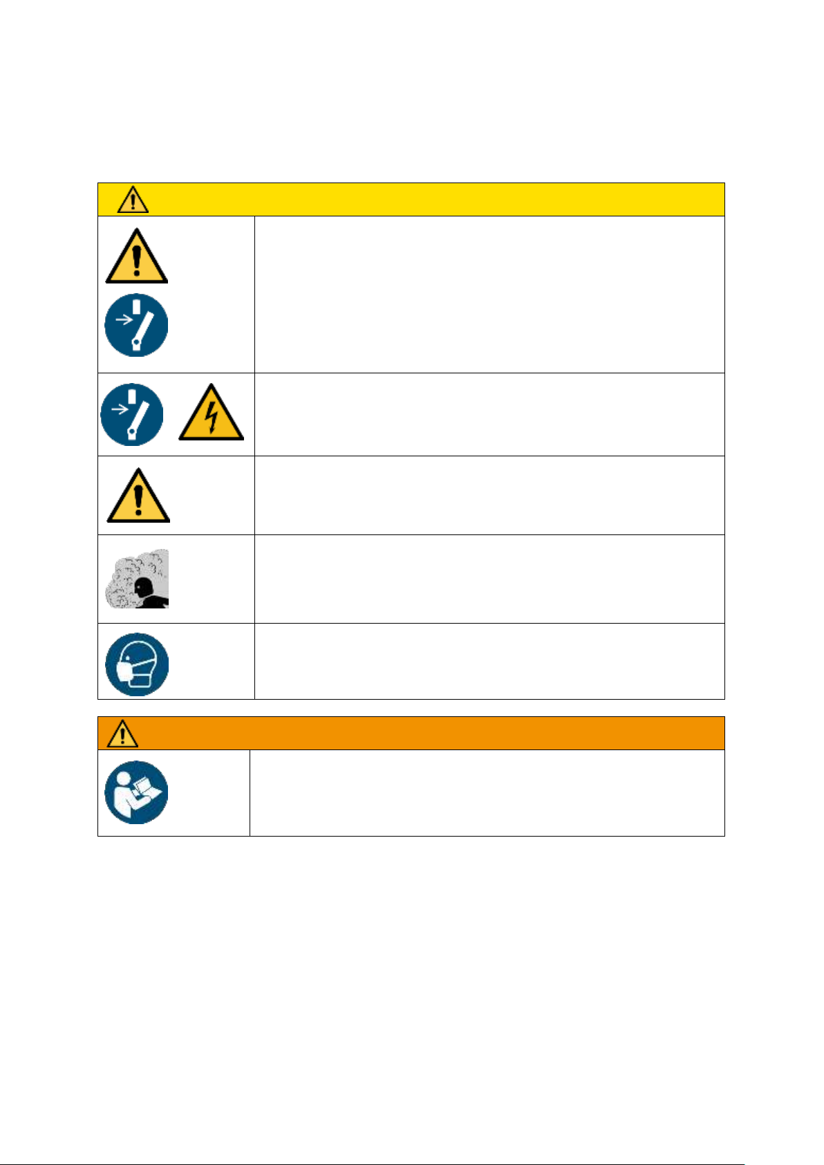
General notes on maintenance
Risk of injuries
►
The production system must be stopped in the area where the system is
being maintained.
►
The system may only be maintained at the workplace in accordance
with the operating instructions.
►
The system must be disconnected and depressurized during maintenance work.
►
The production system must be secured to prevent activation during
maintenance work.
Short-circuit
Electric shock
►
The system must be disconnected during maintenance work.
Careless use of personal protective equipment
Danger to the operator
►
Adapt and wear appropriate personal protective equipment based on
the task being performed.
Dust and fog
Reduced visibility/difficulty breathing
►
Keep the environment clean wherever possible; avoid kicking up large
amounts of dust
Fumes
Irritation of the skin and mucous membranes due to cleaning agents
►
Observe the safety instructions for using the cleaner in question Use
protective equipment if necessary.
WARNING
Risk of injury due to system maintenance by untrained personnel
Serious personal injury
►
The system must only be set up by trained personnel who have read and understood the operating instructions.
8 Maintenance
General Maintenance Instructions 8.1
34 | EN www.schmalz.com 30.30.01.01840/01
Page 35
MAINTENANCE
DANGER
General safety notes on maintenance
Danger to life and limb
►
The system integrator must secure the danger zone.
►
The production system must be stopped in the area where the system is being
maintained
►
The system may only be maintained in accordance with the operating instruc-
►
The system must be disconnected and depressurized during maintenance.
►
The production system must be secured to prevent activation during maintenance work.
Human error
Danger to life and limb
►
Adhere to the operating instructions
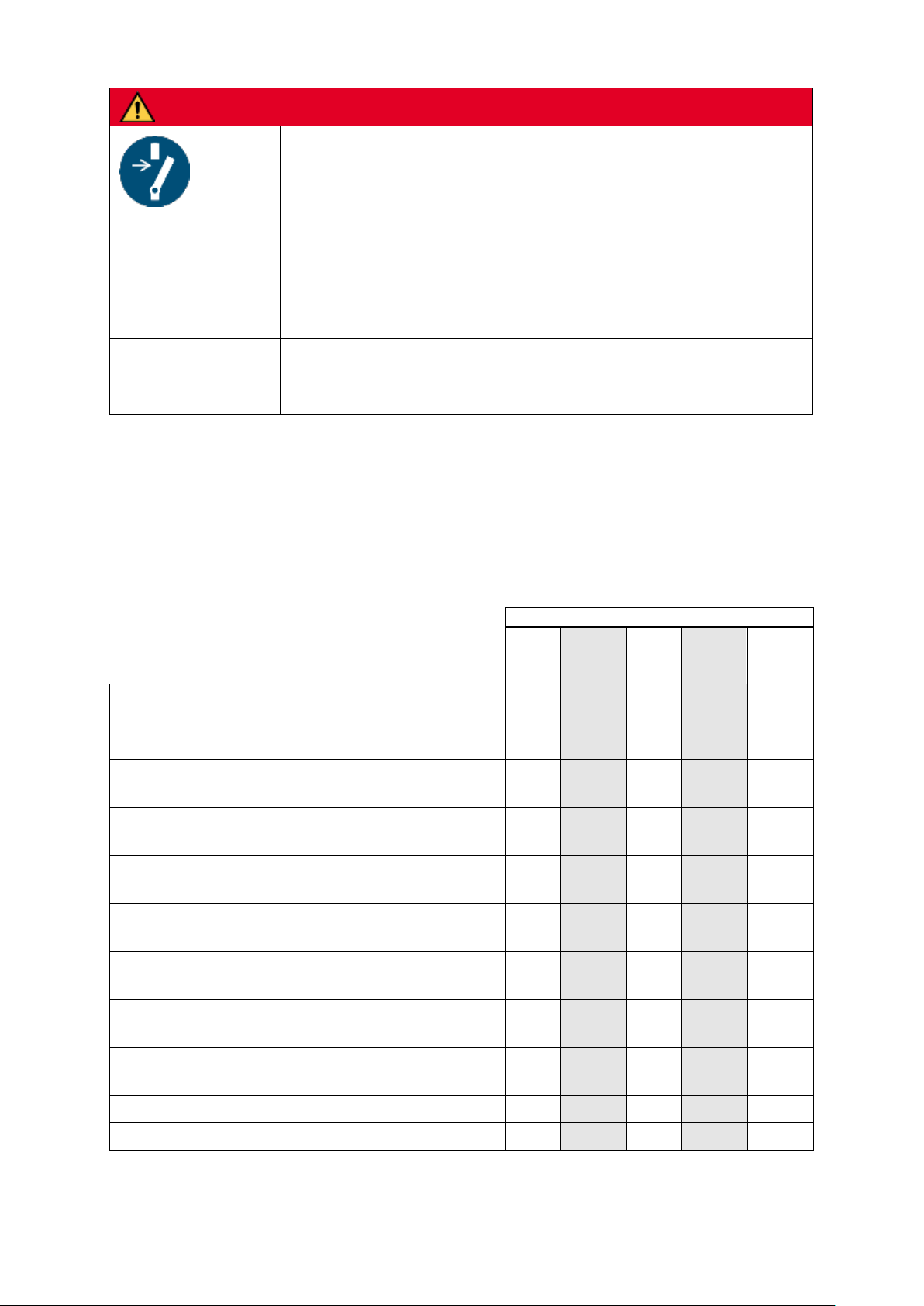
Interval
Daily
Weekly
Month-
ly
Every six
months
Annual
inspec-
tion
Does the vacuum generator make strange noises when
a full load is picked up?
X
Check the ejectors for dirt and clean if necessary
X
Is the electrical installation still OK? Is the cable screw
union secure?
X
Are the vacuum hoses in good condition (not brittle, not
kinked, no worn sections and no leaks)?
X
Check that all the connections are secure, e.g. the
screws, hose clamps, etc.
X
Are the type plate and maximum load plate still attached
to the device?
X
Are the operating instructions available and are the system operators familiar with them?
X
Check all load-bearing parts (e.g. suspension eyes) for
deformation, wear, or other damage.
X
Check the sealing mats for wear, tears and leaks. Replace if necessary.
X
General condition of the device
X
Leak Test
X
If the exterior of the gripper is dirty, clean with a damp cloth.
Operation of the area gripper can draw in dust from the environment. This dust can collect inside the
gripper. The gripper must be cleaned regularly, depending on the amount of dust sucked in.
The necessary maintenance intervals can be increased by taking the following measures.
Maintenance Schedule 8.2
30.30.01.01840/01 www.schmalz.com EN | 35
Page 36
MAINTENANCE
The foam may not be cleaned with a compressed-air gun. This would make the
foam permeable to air in the places where compressed air was applied.
If the sealing plate shows mechanical damage, it can be repaired up to a certain
point using standard vulcanizing adhesive (e.g. adhesive for repairing the inner
tubes of bicycles).
The sealing mat is asymmetrical. Observe the alignment.
Video
www.schmalz.com/
foam
External Vacuum Generator (only FMCB) 8.3
See the relevant operating instructions.
Ejectors (only FXCB) 8.4
See the relevant operating instructions.
Cleaning Agents 8.5
Use cleaning solvents to clean the device (not petroleum ether or corrosive liquids. Petroleum ether or
corrosive liquids destroy the vacuum hoses).
Sealing Plate 8.6
Check the sealing plates for wear, tears and leakage on a regular basis and replace them as necessary. The sealing plates must also be replaced if you notice that the vacuum achieved is constantly
declining when handling the same parts.
Minimum recommended vacuum: 200 mbar when a workpiece is picked up.
For systems that are designed to require higher vacuum, the minimum vacuum must be adjusted accordingly when the sealing plates are replaced.
Replacing the sealing plates
Remove the sealing plate from the quick-change system.
Check the uncovered masking film for clogged flow restrictors; clean
them out with compressed air if necessary.
Clean the surfaces. In order to maintain optimal hold of the new seal-
ing plate, the surface must be free of dust, oil, oxides and adhesive
residues.
Remove the protective film from the adhesive strip of the new sealing
plate.
Press the sealing plate firmly onto the entire surface without any
wrinkles (e.g. with a roller).
The openings of the sealing plate and flow restrictors must be
aligned.
Processing temperature: a range of +10° C to +40° C is recommended for the object tempera-
ture and the ambient temperature.
replacing-sealing-
36 | EN www.schmalz.com 30.30.01.01840/01
Page 37
MAINTENANCE
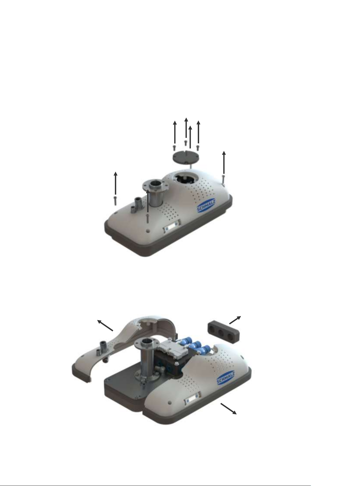
Opening the Gripper to Clean the Ejectors (only FXCB) 8.7
The gripper must be inspected and maintained regularly in order to ensure that it works optimally. To
do so, observe chapter 8.1 General Maintenance Instructions.
Switch the compressed air, electricity and vacuum generator off in advance.
1. Check the cable and hose connections. Check for damaged areas, leakage, ensure that the
screw unions are tight and that no screws are missing, etc.
2. Use a size 2.5 Allen key to unscrew the four M4x20 and four M4x10 housing screws and then pull
the housing cover off upwards.
3. Take the two halves of the housing and carefully put them down to the side. Ensure that no hoses
or cables on the housing become loose.
30.30.01.01840/01 www.schmalz.com EN | 37
Page 38
MAINTENANCE
Housing screws (I)
M4x20, steel
1 Nm
Cover screws (B)
M4x10, steel
1 Nm
Ejector holder caps (E)
Allen key, size 12
2 Nm
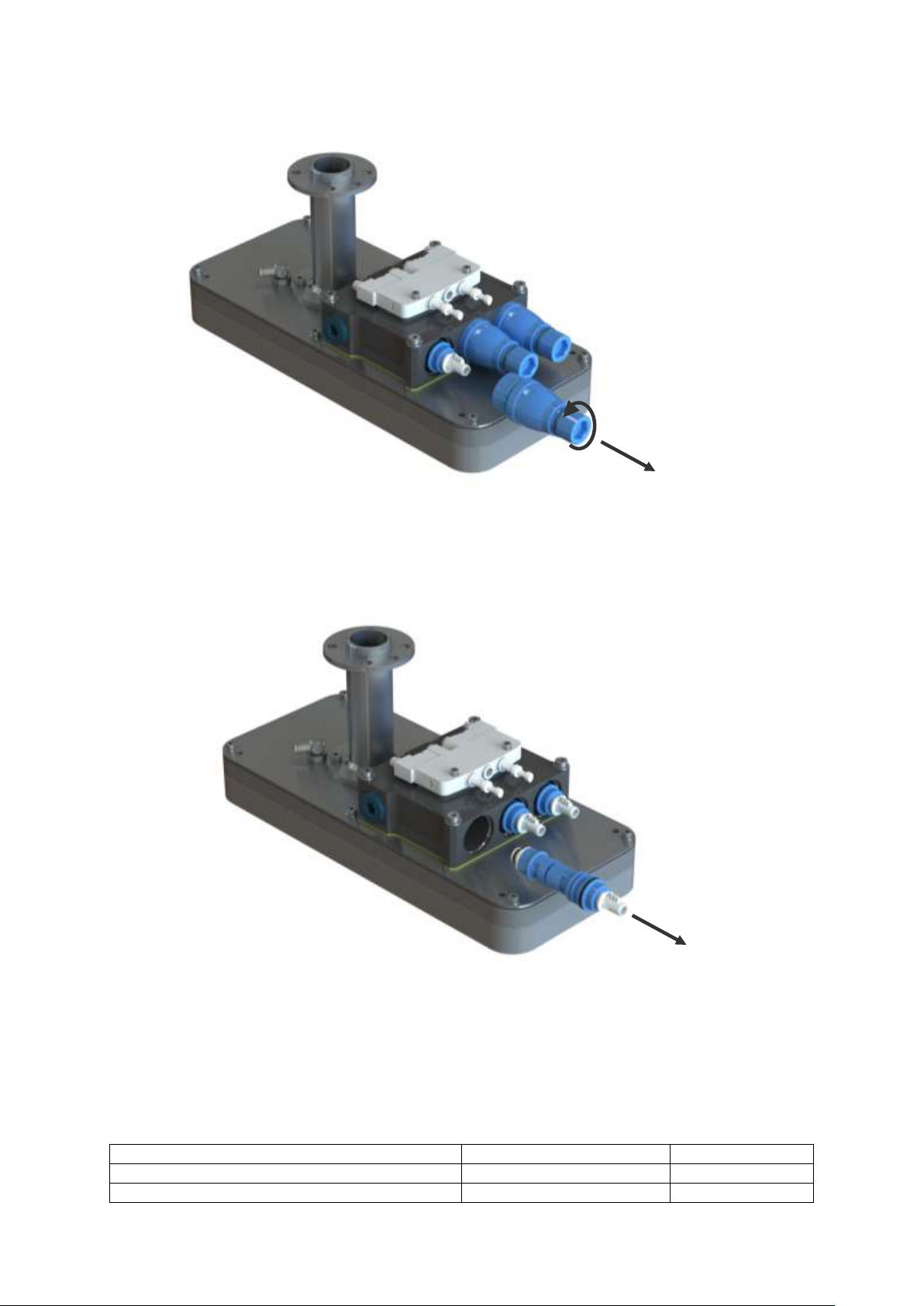
4. Release and remove the holder cap with a size 12 Allen key.
5. Now, remove the ejectors from their mounting bore holes and clean them in accordance with the
corresponding operating instructions.
6. Installation is carried out in the reverse order.
Overview of the Tightening Torque of the Screws 8.8
See the design from chapter 2.2.
38 | EN www.schmalz.com 30.30.01.01840/01
Page 39
MAINTENANCE
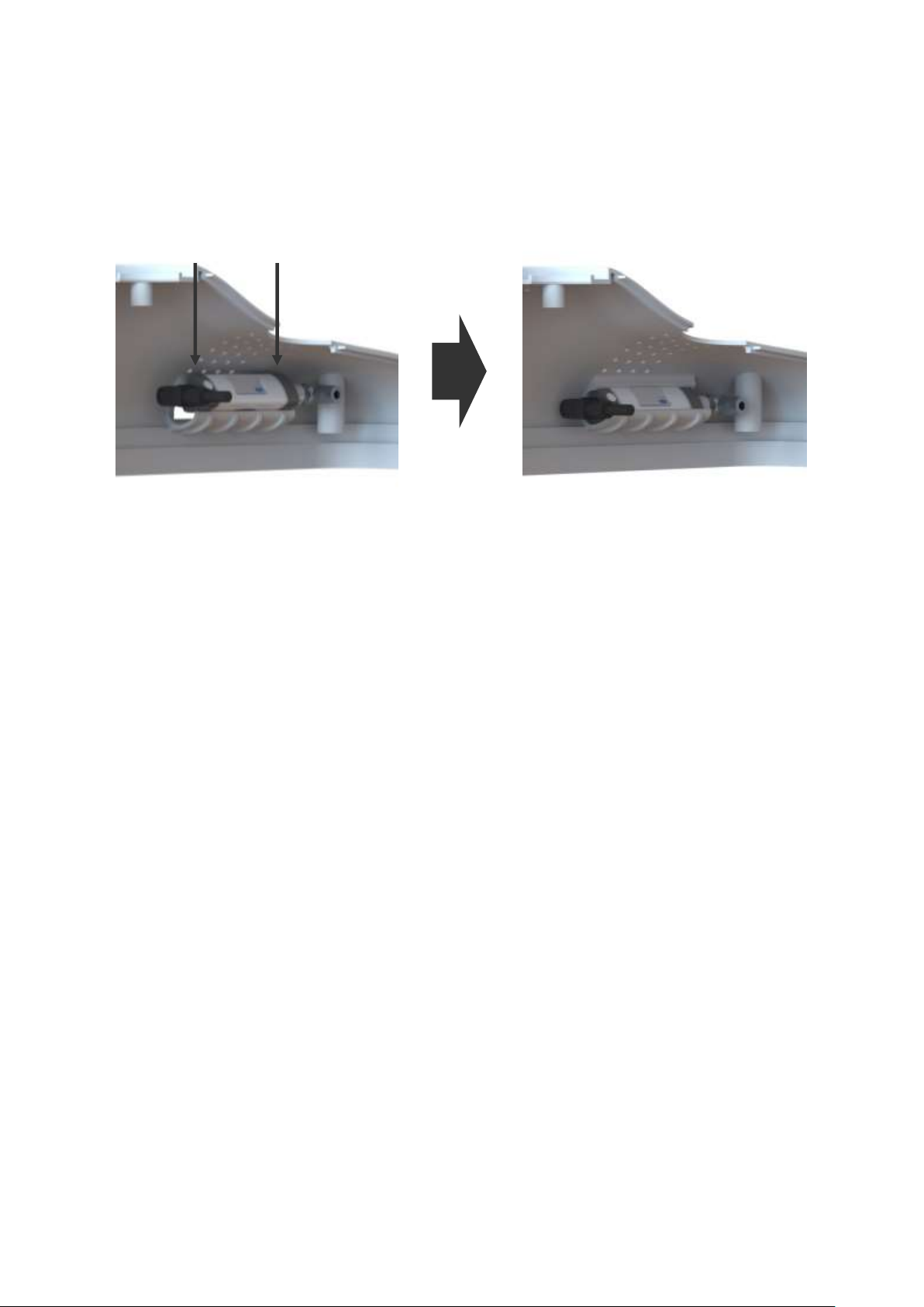
Mounting the Vacuum Switch in the Housing 8.9
To mount the vacuum switch, first connect the electrical cable and vacuum hose. Position the vacuum
switch in the opening on the inside of the housing. Now press the vacuum switch into the mount from
above until the vacuum switch clicks into place. While doing this, ensure that the vacuum switch display faces forward and does not twist, but rather is pushed straight down from top to bottom. Ensure
that the vacuum and electrical connection of the vacuum switch are each on the correct sides.
Checking the System for Leaks 8.10
The flat suction cup must be ready for operation in order to check the system for leaks. Place the flat
suction cups on an even, smooth and airtight surface.
Only FXCB: Switch the valve so that the gripper is in the “Suction ON” state.
The vacuum level can now be read at the vacuum switch.
The measured value may not be lower than –475 mbar.
Only FMCB: Switch on the vacuum generator. The vacuum level can now be read at the vacuum
switch. The measured value should be up to 10% lower than the maximum reachable
vacuum of the vacuum generator used.
Example: The vacuum generator reaches a maximum of –0.5 bar A vacuum of at
least –0.45 bar must be displayed on the gauge.
If the vacuum is not achieved, the system must be checked for leakage as follows.
1. Check the compressed air hoses, hose connections and vacuum hoses (only FMCB) for damage and leakage and replace if necessary.
2. Check the ejectors (only FXCB) for dirt and clean if necessary.
3. Check that the vacuum generator (only FMCB) is fully functional.
30.30.01.01840/01 www.schmalz.com EN | 39
Page 40
SPARE AND WEARING PARTS
ATTENTION
Incorrect disposal of the system or individual components
Environmental damage
►
Disposal according to national guidelines.
1
3
5
7
6
14
10
19
4
13 2 9
11
12
17
18
16
15
9 Spare and Wearing Parts
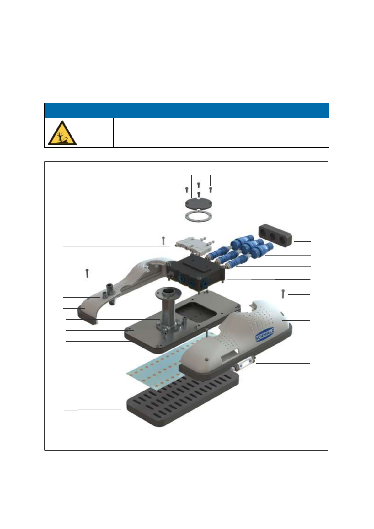
We guarantee this device pursuant to our General Terms and Conditions of Sale and Delivery. The
same applies to spare parts, provided that these are original parts supplied by us. We are not liable for
any damage resulting from the use of non-original spare parts or accessories. Wearing parts are not
covered by the warranty.
40 | EN www.schmalz.com 30.30.01.01840/01
Page 41
SPARE AND WEARING PARTS
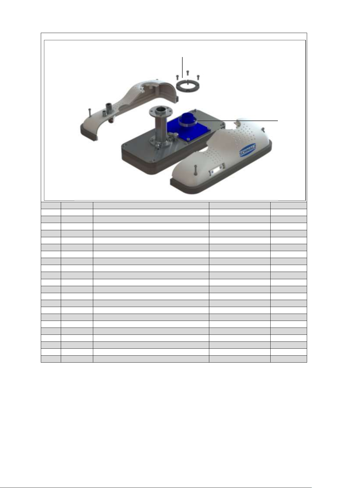
Item
Quantity
Description
Part no.
Legend
11
1
Housing cover
10.01.43.00012
S 2 4
Machine screw M4x10
20.01.02.04028
S
31
1
Silencer
10.01.43.00005
S
41
1
Solenoid valve
10.01.11.03420
S
51
3
Holder cap SHC-2-22
10.02.01.01512
S
61
3
Ejector module SEP HF 2 13 22
10.02.01.01347
S
71
1
Ejector Block
10.01.11.03497
S
8*1
1
Ejector block (contains items 5, 6 and 7)
10.01.11.03499
S 9 1
Plug-in screw union Ø 10 mm
10.08.02.00251
S
10
4
Machine screw M4x20
20.01.02.04090
S
11
1
Electrical connection plug
21.04.05.00486
S
12
1
Housing (set)
10.01.43.00021
S
13
1
Flange module
10.01.11.03496
S
14
1
Housing (set)
10.01.43.00021
S
15
1
Cover plate
10.01.11.03626
S
16
1
Suction plate (pre-assembled)
10.01.43.00008
S
17
1
Vacuum Switch VSi
10.06.02.00577
S
18
1
Masking film
10.01.11.03375
S
19
1
Sealing plate
10.01.11.03658
W
202
1
Housing cover
10.01.43.00009
S
212
1
Hose clamp assembled
10.01.11.03647
S
22*
0.2 m
Hose Ø 6 mm
10.07.09.00141
S
20
21
* Items not shown
1
Only FXCB
2
Only FMCB
S= Spare part, W= Wearing part
30.30.01.01840/01 www.schmalz.com EN | 41
Page 42
ACCESSORIES
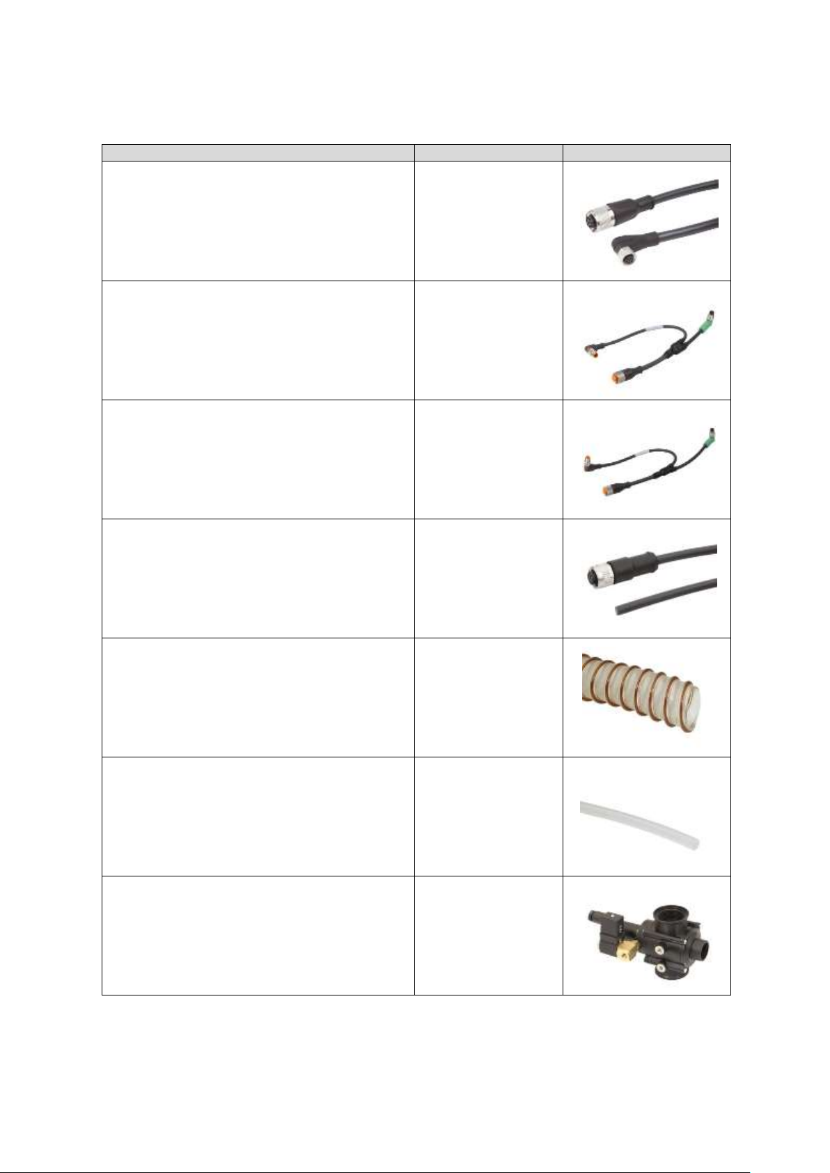
Description
Part number
Connection cable for Universal Robots UR3,5,10
21.04.05.00350
Connection cable for KUKA LBR iiwa7,14
MF electrical
21.04.05.00361
Connection cable for KUKA LBR iiwa7,14
MF pneumatic
21.04.05.00362
Connection cable with loose strands
Length 5000mm
21.04.05.00079
Vacuum hose Ø 32 mm for connecting the grip-
per to an external blower (only FMCB)
10.07.09.00036
Compressed air hose Ø 10 mm for connecting
the gripper to the compressed air source
10.07.09.00084
Solenoid valve for controlling the vacuum (only
FMCB)
10.05.02.00068
10 Accessories
42 | EN www.schmalz.com 30.30.01.01840/01
Page 43
ACCESSORIES
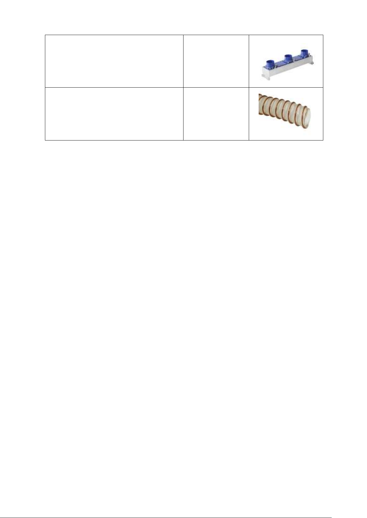
Vacuum distributor for operating multiple grippers
with one shared blower
(only FMCB)
10.01.43.00013
Vacuum hose Ø 60 mm for connecting the vacuum distributor to an external blower (only FMCB)
10.07.09.00065
30.30.01.01840/01 www.schmalz.com EN | 43
Page 44
PNEUMATIC CIRCUIT DIAGRAM
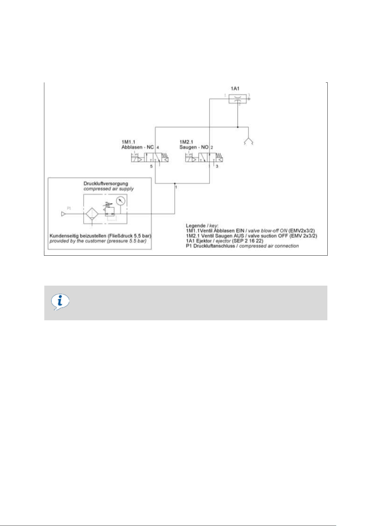
Maximum overpressure
The overpressure in the gripper must be limited to a maximum of 0.2 bar. For example, no continuous blow-off pulse as long as the gripper is placed on a workpiece
in the waiting position, or similar.
11 Pneumatic Circuit Diagram
Pneumatic Circuit Diagram FXCB 11.1
Before initiating the blow-off pulse, ensure that the gripper (with attached workpiece) is not pressed
against a solid surface. The workpiece must be able to freely detach from the gripper.
44 | EN www.schmalz.com 30.30.01.01840/01
Page 45
PNEUMATIC CIRCUIT DIAGRAM
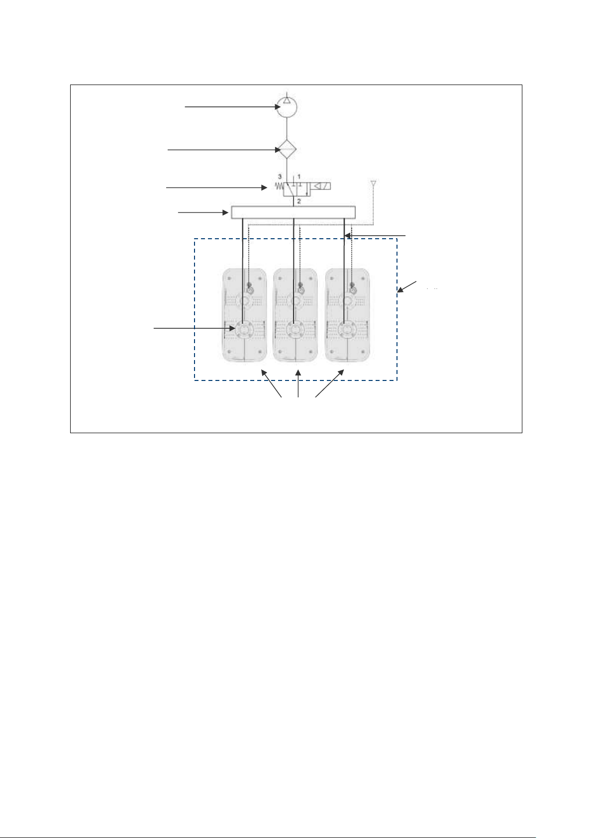
Compressed air source
Optimum flowing compressed air pressure 5.5 bar
Vacuum distributor
Vacuum filter
Hose
clamps/connector
Vacuum
Included in
Vacuum valve
(see page 39)
Hose Ø32mm
(see page 39)
Flat suction cup FMCB
Vacuum generator
Pneumatic Circuit Diagram FMCB – Parallel Circuit 11.2
30.30.01.01840/01 www.schmalz.com EN | 45
Page 46

OTHER APPLICABLE DOCUMENTS
12 Other Applicable Documents
EC Declaration of Incorporation FXCB FMCB 30.30.01.01787
Operating instructions for the ejector module ecoPump (only for FXCB) 30.30.01.00600
Operating instructions for the vacuum switch VSi 30.30.01.00956
46 | EN www.schmalz.com 30.30.01.01840/01
Page 47
Global contact
Our sales network of local field representatives, international subsidiaries and trade
partners ensures quick and competent information and consultation in more than 50
countries worldwide.
www.schmalz.com/salesnetwork
Online documentation
Conveniently download catalogs, operating instructions and CAD data and get comprehensive information about our products and services.
www.schmalz.com/dokumentationen
“How to” videos
In short, easy-to-understand videos we explain the extensive features of our products. Take a look, it’s worth it!
www.schmalz.com/gewusst-wie
J. Schmalz GmbH
Johannes-Schmalz-Str. 1
72293 Glatten, Germany
Phone +49 (0)7443 2403-0
Fax +49 (0)7443 2403-259
[email protected]
www.schmalz.com
30.30.01.01840/00| 03.2019
World of Vacuum Technology
Schmalz Services
Further services ranging from consultation to training can be found at
www.schmalz.com/services
www.schmalz.com
 Loading...