

Schlage BE468 User Manual
*P516-872*
Place Label Here
Default Codes
P516-872
Connected Touchscreen
INSTALLATION INSTRUCTIONS
MODEL BE468
Since this is an electronic lock, please follow the steps in order as shown. If you skip a step, you may have to perform a factory default reset, and
start over.
Tools Needed:
• Phillips Screwdriver
DO NOT use a power drill! A manual or electric screwdriver is safe,
but a power drill may damage the lock.
Installation Notes
• DO NOT use a power drill for installation!
• Please read all instructions before calling customer support.
• Please call customer support before returning the product.
• DO NOT install the batteries before installing the lock! Follow the
directions in order.
1 Check the current door/frame alignment
Because the bolt on this lock is extended automatically, it is important
that the door and frame are aligned. Use this checklist to determine if
your current alignment will work without any adjustment.
I can lock the door without pushing, pulling or liing the door.
My door alignment— the ability to lock the door easily and
smoothly— stays the same with changing seasons.
When the door is closed, there is space for the deadbolt to
extend 1” into the frame when locked.
If you could not check every box in the checklist, you will need to
adjust your door and/or frame. Please visit answers.schlage.com for
more information.
Default
Programming
Code
Default User
Codes
Possibly Needed Tools:
• Tape Measure
• Flathead Screwdriver
• Pencil
• Wood Block
• Hammer
• If you previously installed this lock on another door, you MUST
perform a Factory Default Reset FIRST! See Step 9 for more
information.
• The lock is designed for the following operating temperatures:
Outside Lock Body (exterior mounted): -31°F (-35°C) to 151°F
(66°C)
Inside Lock Body (interior mounted): 14°F (-10°C) to 120°F (49°C)
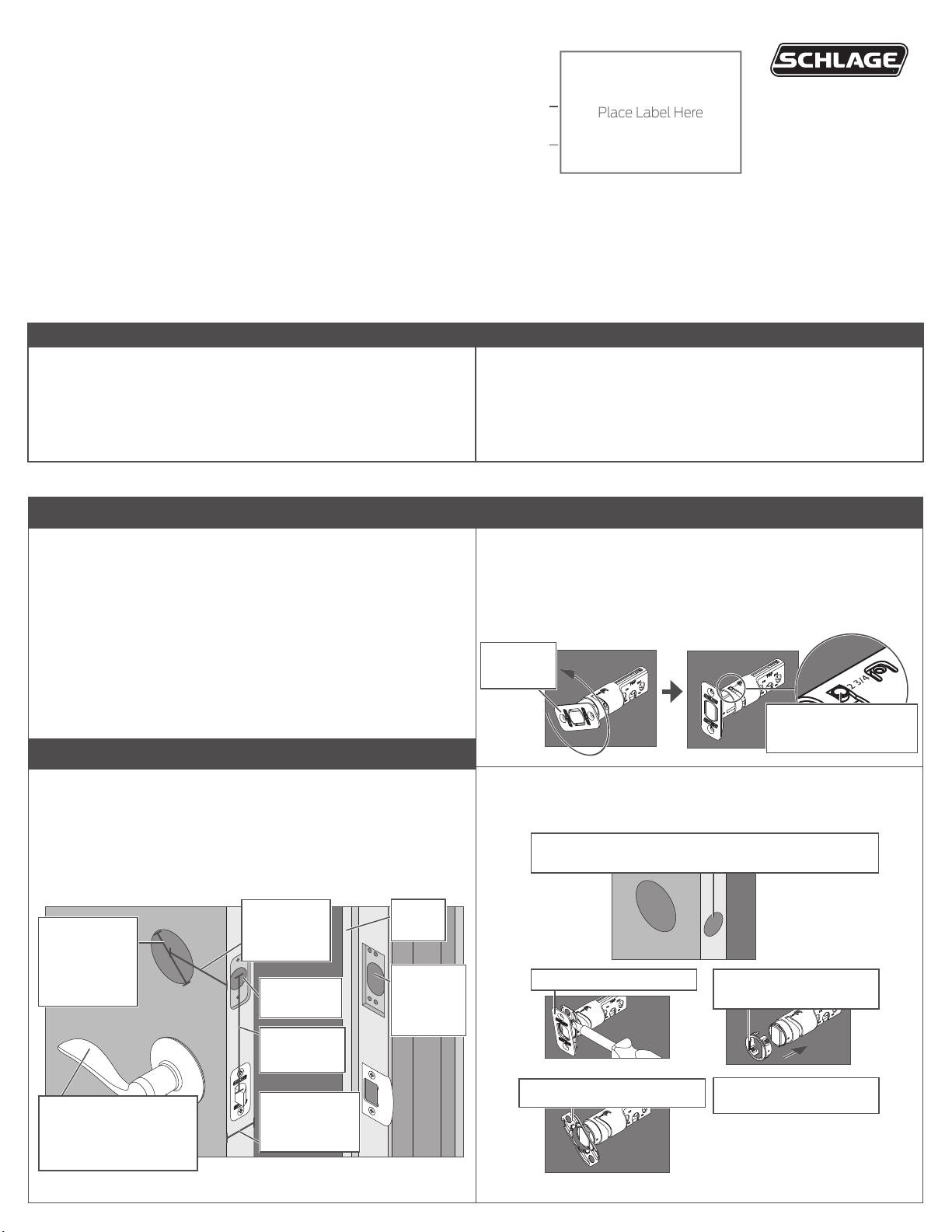
3 Install bolt and strike
3a Adjust bolt length, if necessary.
• If the backset (see step 2) of your door was 2C\,” (60 mm),
you do not need to do anything. Proceed to step 3b.
• If the backset (see step 2) of your door was 2C\v” (70 mm), you
need to adjust your bolt. Twist the faceplate until the button pops
into the 2C\v” space.
Twist the
faceplate.
Make sure the button
pops into place.
2 Check door/frame dimensions
Measure the dimensions shown. If your door dimensions do not
match, you will need to change your door preparation.
L If your door is thicker than 1C\v”, you will need a thick door kit. Please
call Customer Service at 1-888-805-9837.
L Mark your crossbore and backset measurements on this
page. You will need these measurements for installation. Either
measurement is normal.
Crossbore
Diameter
2Z\,” (53 mm)
OR
1Z\x" (38 mm)
Backset
2C\,” (60 mm)
OR
2C\v” (70 mm)
1” (25 mm)
Hole
Minimum 5"
(127 mm)
Door
Stop
Hole at
least 1”
(25 mm)
deep.
3b Change the faceplate, if necessary.
L In step 3c, your installation will depend on which kind of door edge
you have.
If your door looks like this, complete the steps below.
1. Pry the faceplate off.
No Mortise
3. Slide the round
faceplate into place.
This lever represents your
current knob or lever,
which may be already
installed.
Door Thickness
1C\,” to 1C\v”
2. Remove the backplate.
4. Go to Step 3c, Figure
B.

3c Install the bolt into the door.
IMPORTANT!
Retract the bolt before continuing to step 3c!
4b Install the Support Plate on the inside of the door.
L Make sure the Touchscreen and Support Plate are straight on the
door before tightening the screws. Tighten screws fully to prevent
the lock from moving over time.
Choose the picture below that matches your door.
FIgure A: Mortise Figure B: No Mortise
Actual Size (2)
Make
sure the
word
TOP
faces up
when
installing
the bolt.
OR
Use a block of wood
and a hammer (not
included) to tap the
bolt into place. You
don’t need to use the
screws.
3d Install the strike into the frame.
Install all the parts shown for maximum security.
L In order to maintain BHMA Grade 2, you must install the included
reinforcement plate and strike.
L The reinforcement screws may not fit on doors with sidelights.
Door Stop
Actual Size (2)
Make sure
this hole is at
least 1” (25
mm) deep.
Have someone hold the Touchscreen
TOP
Route the cable
through the slot.
on the outside of the door while you
tighten the screws.
Make sure the indented circle is
facing the door.
Actual Size (2)
5 Install the Inside Assembly
5a Remove the battery cover from the Inside Assembly.
ELECTROSTATIC
DISCHARGE WARNING!
Avoid contact with the
circuit board!
L Do not remove the battery tray (not shown).
5b Connect the cable to the Inside Assembly.
L Locate the screws in step 5d before beginning this step so they will
be handy when you need them.
Reinforcement Screws: Actual Size (2)
4 Install the Touchscreen Assembly
4a Install the Touchscreen on the outside of the door.
L The clips snap into the crossbore (see step 2) to assist in holding
the keypad on the door.
L The Touchscreen Assembly should install smoothly. If it does not,
check that the bolt is set to the correct backset (see step 2).
Clips snap into
the crossbore.
Align the tab
with the notch.
L NOTE: If you have a crossbore (see step 2) that is slightly less
than 2Z\,” (54 mm), the lock may not install smoothly. You can
remove the spacer. Always remove the spacer for a 1Z\x” (38 mm)
crossbore.
Route the cable
under the bolt.
The connector fits only one
way. Match the dot on the
connector with the dot on the
circuit board.
5c Install the Inside Assembly.
1. Align the tab with the notch as shown.
2. Route the cable into the channel.
3. Then slide the Inside Assembly towards the door.
Route the cable into the channel to avoid crimping the cable.
Align tab
with notch.
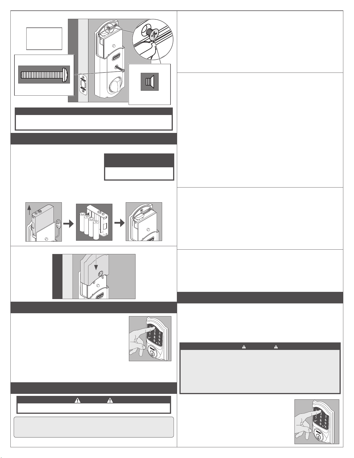
5d Secure the Inside Assembly to the Support Plate.
-
Install the
lower screw
first.
Actual Size
Actual Size
8-32 x 1Z\,”
8-32 x .187 UP
FHMS
NOTE
Please do not rotate the thumbturn at this time. It may not rotate
easily. Setup will be performed aer installation is complete.
6 Install the Batteries
6a Install the batteries into the battery tray.
1. Unsnap the connector.
2. Remove the battery tray.
3. Install four fresh, high-quality
alkaline AA batteries.
L Lithium batteries may cause
undesired operation, and are not recommended.
4. Carefully replace the battery tray, with the batteries facing the door.
5. Snap the connector back into place.
-
+
-
+
+
-
+
6b Install the battery cover.
ELECTROSTATIC
DISCHARGE WARNING!
Avoid contact with the
circuit board!
8a Extend the bolt (lock) using the inside thumbturn.
1. Close the door.
2. Rotate the thumbturn toward the door jamb to extend the bolt.
Was this operation smooth?
YES: Continue to Step 8b.
NO: You may need to adjust your door/frame. Continue to
Step 8b for further testing, or go to answers.schlage.com and
watch the video Proper Alignment of Door and Frame for a
Smoothly Operating Lock for adjustment instructions.
8b Extend the bolt (lock) using the Touchscreen.
1. Unlock the door using the thumbturn if you have not already.
2. Take the key and the Default User codes with you!
Go outside and close the door.
3. Press the Schlage Button.
4. The bolt should extend.
Did the bolt extend (is the door locked)?
NO: You need to adjust your door/frame. Go to answers.
schlage.com for adjustment instructions.
YES: Did the bolt take two tries to extend? Each try sounds
like two cycles.
NO: Alignment is correct.
YES: The lock has both a low power and high power
mode. It will try low power first and then high power when
unsuccessful. Aer three times using high power, it will
always use the high power mode instead of trying twice each
time. You may want to adjust your door/frame to conserve
battery power, but it is not necessary.
8c Retract the bolt (unlock) using the Touchscreen.
1. Press Schlage Button to activate keypad.
2. Enter one of the default User Codes into the lock.
3. The bolt should retract.
Did the bolt retract (is the door unlocked)?
NO: Use the key to unlock the door. You need to adjust your
door/frame. Go to answers.schlage.com for adjustment
instructions.
YES: Alignment is correct.
8d If the lock failed to lock or unlock:
1. If the Touchscreen did not light up, you may have a power problem.
Install fresh batteries and make sure the battery connector is
connected (see step 6a).
2. If the lock had power but you need to adjust your door/frame,
please go online to answers.schlage.com for complete
adjustment instructions and videos.
7 Set up the Lock
1. Open the door if it is not already open.
2. Press the Schlage button first to enable the
backlight.
3. Enter one of the Default User Codes into the
lock (see front of instructions).
4. The lock will perform a setup routine. Wait
until the bolt stops moving before continuing.
L If the Touchscreen did not light up during this
step, you may have a power problem. Install
fresh batteries and make sure the battery wires are connected
(see step 6).
8 Test the Lock
CAUTION
Keep the key with you during testing to avoid being locked out!
L For complete information about programming, see the
Programming the Touchscreen and Troubleshooting
sections in the User’s Guide found at answers.schlage.com.
9 Factory Default Reset
When should you perform a Factory Default Reset?
• If you want to move the lock to a different door, you need to restore
default settings, move the lock to the new door, and then set up the
lock again.
• If you have forgotten your Programming Code, you can restore the
default codes.
WARNING
Locate the default Programming and User Codes on the back of the
Inside Assembly or on the original instruction sheet before beginning!
Default Programming and User Codes will be restored. All existing
User Codes and current Programming Code will be erased.
CUSTOMER SERVICE CANNOT RETRIEVE LOST DEFAULT
CODES! DO NOT RESTORE FACTORY SETTINGS UNLESS
1. Disconnect the batteries. See Install the
Batteries.
2. Press and hold the Schlage Button.
3. While holding the Schlage Button, reconnect
the batteries.
4. Release the Schlage Button.
5. The inside indicator and green check will blink if
the Factory Default Reset is successful.
YOU CAN LOCATE THE DEFAULT CODES.

6. If you are moving the lock to a new door, install the lock on that
door before continuing.
7. To check that the lock was reset, press the Schlage Button and
enter one of the Default User Codes. If the reset was successful, the
Default User Codes will unlock the deadbolt.
L The lock must be set up again aer the reset is complete (see
Step 7 Set up the Lock).
L Z-Wave network settings are maintained through Factory Default
Reset.
10 Z-Wave Functions
10a About Z-Wave
• This lock may be included into any Z-Wave network, from any
manufacturer.
• Listening nodes from any manufacturer can act as repeaters to
extend network range.
• The lock will have limited functionality if included with a nonsecure controller.
• Configuration parameters and association group information can
be found at answers.schlage.com.
L The Z-Wave radio is disabled by default to conserve battery
life. When the lock is included for the first time, the radio is
automatically enabled.
L If you no longer wish to use the lock with a Z-Wave network,
make sure to exclude the lock to conserve battery life.
10b Z-Wave Function Descriptions
Include the Lock Turns the Z-Wave radio on and enrolls the lock.
Verify Lock
Inclusion
Exclude the Lock Excludes the lock and turns the Z-Wave radio
To Include/Exclude the lock, you must first put your Z-Wave
Controller into inclusion mode:
1. Put the controller or panel in Include/Exclude mode.
L This procedure will vary depending on controller manufacturer.
2. Extend the bolt on the lock and then perform the following:
Include/
Exclude the
Lock
L The programming indicator will flash rapidly while inclusion is in
process.
To verify Inclusion:
1. Remove the battery cover. See Install the Batteries.
2. Disconnect the battery connector.
3. Observe the indicator in the center of the printed circuit board while
reconnecting the battery connector.
4. The indicator will blink if the lock is included.
Please call customer support before returning the product.
Toll-Free Calling From:
Visit our web site for videos, FAQs and more:
Verifies that the lock is included in a Z-Wave
network.
off.
6 Digit
Programming
Code
The lock
included/
excluded
was
OR
The lock
was not
included/
excluded
NEED HELP?
U.S.A.: (888) 805-9837
Canada: (800) 997-4734
Mexico: 018005067866
answers.schlage.com
11 Programming Procedures
L Determine how long you want
your User Codes to be BEFORE
adding any User Codes. If you
change the User Code length,
all existing User Codes will be
deleted!
1. Open the door and extend the deadbolt before beginning.
2. If you make a mistake, press the Schlage Button to leave
Programming Mode, and then start over.
WRITE YOUR PROGRAMMING CODE HERE FOR EASY ACCESS
FUNCTION
Add User Code
Delete User
Code
Change
Programming
Code
Enable Vacation
Mode
Disable Vacation Mode
Enable/Disable
Beeper
Delete ALL User
Codes
Warning
Enable/Disable
Lock & Leave
Change User
Code Length
Warning
Enable/Disable
Auto-Lock
Temporarily Disable
Auto-Lock
(deadbolt should be
locked to begin)
Restore
Auto-Lock
Include/Exclude
the Lock
ENTER PROGRAMMING
MODE (PRESS)
6 Digit
Programming
Code
6 Digit
Programming
Code
6 Digit
Programming
Code
6 Digit
Programming
Code
6 Digit Programming Code
6 Digit
Programming
Code
6 Digit
Programming
Code
Removes ALL User Codes from the lock. User Codes cannot be retrieved aer they are
deleted!
6 Digit
Programming
Code
6 Digit
Programming
Code
Changing the User Code length will delete all existing User Codes! User Codes cannot
be retrieved aer they are deleted!
6 Digit
Programming
Code
Relock the deadbolt using the thumbturn.
6 Digit
Programming
Code
L Programming Mode will
automatically time out aer 30
seconds of inactivity.
FUNCTION STEPS
(PRESS)
New 4-8 Digit
User Code
4-8 Digit User
New 6 Digit
Programming
Programming
Desired User
Code Length
4-8 Digit
User Code
The lock was
included/
excluded
Same New
4-8 Digit User
Add another code
Code
Code
6 Digit
Code
Same 4-8 Digit
User Code
Delete another
code
Same New
Programming
Disable: 2 blinks + 2 beeps
Disable: 2 blinks + 2 beeps
Same Desired
User Code
Length
Disable: 2 blinks + 2 beeps
Within 5 seconds,
manually lock and unlock
the deadbolt using the
thumbturn.
OR
The lock was
not included/
excluded
Code
6 Digit
Code
Enable:1 blink + 1 beep
Enable:1 blink + 1 beep
Enable:1 blink + 1 beep
VERIFY
2 blinks +
2 beeps
2 blinks +
2 beeps
2 blinks +
2 beeps
1 blink +
1 beep
2 blinks +
2 beeps
2 blinks +
2 beeps
2 blinks +
2 beeps
1 blink +
1 beep
2 blinks +
2 beeps
or
or
REGISTER YOUR PRODUCT
Document your purchase and register your warranty at
RegisterMySchlage.com
© Allegion 2014
Printed in USA
P516-872 Rev. 03/14-a
 Loading...