

Schischek RedMax-Y Series, RedMax-VAS Series, RedMax-CTS Series, RedMax-YF Series, RedMax-5.10-Y Quick Start Manual
...Page 1
EXPLOSIONPROOF
www.schischek.com
Schischek GmbH Germany, Muehlsteig 45, Gewerbegebiet Sued 5, 90579 Langenzenn, Tel. +49 9101 9081-0, Fax +49 9101 9081-77, E-Mail [email protected]
RedMax-S-Y_en
V01 – 20-Apr-2016
RedMax ¼ turn actuators – size S
Electrical, explosion proof rotary actuators
3-pos. / 0...10 VDC / 4...20 mA control mode, with feedback, 24...240 VAC/DC, 95° angle of rotation
RedMax - ... - Y
RedMax - ... - YF
RedMax - ... - CTS
RedMax - ... - VAS
Subject to change!
5/ 10 Nm, 15/ 30 Nm without and 5/ 10 Nm, 15 Nm with safety operation (spring return)
ATEX tested in acc. with directive 2014/ 34/ EU for zone 2, 22
Compact. Easy installation. Universal. Cost effective. Safe.
Type Torque Supply Motor running time Spring return Control mode Feedback Wiring diagram
RedMax- 5.10 - Y 5 / 10 Nm 24...240 VAC/DC 7,5 / 15 / 30 / 60 / 120 s/90° – 3-pos., 0...10 VDC, 4...20 mA 0...10 VDC, 4...20 mA SB 5.0 – 5.3
RedMax-15.30 - Y 15 / 30 Nm 24...240 VAC/DC 7,5 / 15 / 30 / 60 / 120 s/90° – 3-pos., 0...10 VDC, 4...20 mA 0...10 VDC, 4...20 mA SB 5.0 – 5.3
RedMax- 5.10 - YF 5 / 10 Nm 24...240 VAC/ DC 7,5 / 15 / 30 / 60 / 120 s/ 90° 3 or 10 s /90° 3-pos., 0...10 VDC, 4...20 mA 0...10 VDC, 4...20 mA SB 5.0 – 5.3
RedMax- 15 - YF 15 Nm 24...240 VAC/DC 7,5 / 15 / 30 / 60 / 120 s/90° 3 or 10 s / 90° 3-pos., 0...10 VDC, 4...20 mA 0...10 VDC, 4...20 mA SB 5.0 – 5.3
RedMax- ... - CTS Types as above with aluminium housing and seawater resistant coating (cable glands brass nickel-plated)
RedMax- ... - VAS Types as above with stainless steel housing for aggressive ambient (cable glands brass nickel-plated)
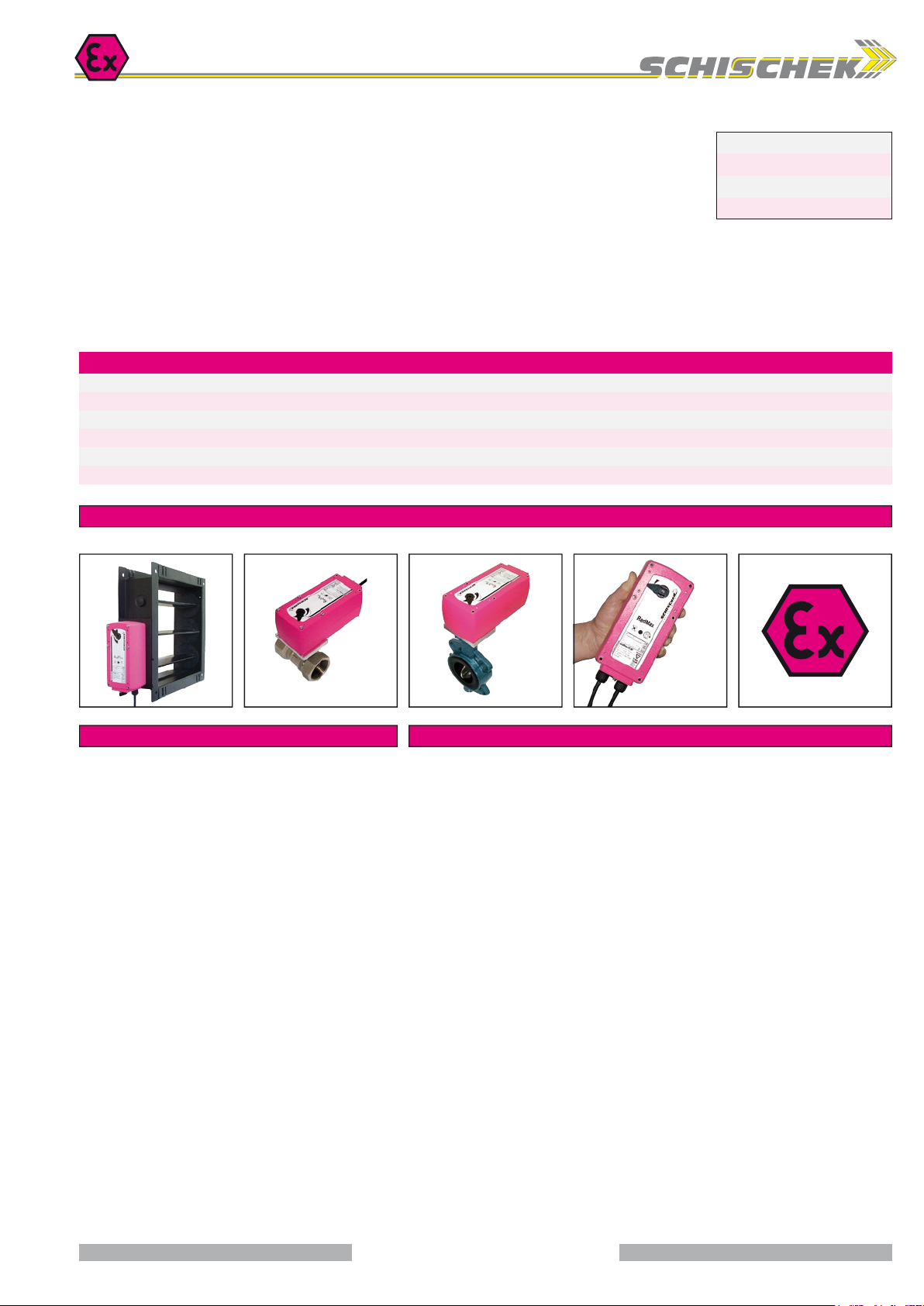
Product views and applications
Ball valve Throttle valveSafety damper
Description Highlights
The RedMax actuators are a revolution for safety, control and shut-off
dampers, VAV systems, ball valves, throttle valves and other motorized
applications for HVAC systems in chemical, pharmaceutical, industrial
and offshore/onshore plants, for use in Ex-areas zone 2 (gas) and zone
22 (dust).
Highest protection class (ATEX) and IP66 protection, small dimensions,
only 3,5 kg weight, universal functions and technical data, an integrated
heater and an optional stainless steel housing guarantee safe operation
even under difficult environmental conditions. High quality brushless
motors guarantee long life.
All actuators are programmable and adjustable on site. Special tools or
equipment are not required. Motor running times and torques as well as
spring return times, according to the actuator type, are selectable or
adjustable on site. The integrated universal power supply is self adaptable
to input voltages in the range of 24...240 VAC/DC. Furthermore it is
possible to perform control signal inverting and compulsion control by
certain connections. The actuators are 100 % overload protected and
self locking.
...Max-...-YF actuators are equipped with spring return fail safe function.
Standard shaft connection is a double square direct coupling with
12 × 12 mm.
Different accessories are available to adapt auxiliary switches, terminal
boxes or adaptions for ball valves and throttle valves and other armatures.
► For all type of gas, mists, vapours and dust for use in zone 2 and 22
► Universal supply unit from 24…240 VAC/ DC
►5 different motor running times 7,5–15– 30 –60–120 s / 90°, adjustable on site
► 2 different spring return running times ~ 3–10 s/ 90°, selectable on site
► 3-pos. and 0...10 VDC, 4...20 mA control mode with or without spring return function
► Feedback signals 0...10 VDC and 4...20 mA
► Reverse function
► 5–10 –15 – 30 Nm actuators in the same housing size
► 100 % overload protected and self locking
► Compact design and small dimension (L × W × H = 210 × 95 × 80 mm)
► Direct coupling to the damper shaft with double square connection 12 × 12 mm
► 95° angle of rotation inclusive 5° pretension
► Robust aluminium housing (optional with seawater resistant coating) or in stainless steel
► IP66 protection
► Simple manual override included + preparation for comfortable manual override
► Gear made of stainless steel and sinter metal
► Weight only ~ 3,5 kg
► Integral heater for ambient temperatures down to −40 °C
► Integral safety temperature sensor
► Integral equipment for manual adjustment (push button, lamp, switch)
► Preparation for adaptable and adjustable auxiliary switches type ...Switch
1 / 4
Page 2
EXPLOSIONPROOF
www.schischek.com
Schischek GmbH Germany, Muehlsteig 45, Gewerbegebiet Sued 5, 90579 Langenzenn, Tel. +49 9101 9081-0, Fax +49 9101 9081-77, E-Mail [email protected]
RedMax-S-Y_en
V01 – 20-Apr-2016
RedMax-...-Y RedMax-...-YF
Special options ... -CTS ... -VAS
Technical data RedMax- 5.10 -Y RedMax- 15.30 -Y RedMax- 5.10 -YF RedMax- 15 -YF
Torque motor (min.) 5 / 10 Nm selectable on site 15 / 30 Nm selectable on site 5 / 10 Nm selectable on site 15 Nm
Torque spring (F) – – min. 10 Nm min. 15 Nm
Dimension of external torque Above mentioned torques are min. torques in blocked position, external torque should be max. 80 % of max. actuator torque but min. 3 Nm
Supply voltage / frequency 24...240 VAC/DC, ± 10 %, self adaptable, frequency 50...60 Hz ± 20 %
Power consumption max. starting currents see
Protection class Class I (grounded)
Angle of rotation and indication 95° incl. ~ 5° pretension, mechanical value indication
Working direction Selectable by left/right mounting to the damper/valve shaft
Motor running times 7,5 / 15 / 30 / 60 / 120 s/90° selectable on site
Motor Brushless DC motor
Spring return (F) – – spring return in the event of loss of power
Spring return running time (F) – – spring return in ~ 3 or 10 s/90°, selectable on site
3 sec. mode – spring return – – in acc. with external torque ~ 3 to 4 s/90° angle of rotation
Safety operations at 10 sec. min. 10,000 in acc. with construction of damper and ambient
at 3 sec. min. 1,000 in acc. with construction of damper and ambient
Response time spring return up to 1 sec. after power failure
Control mode Y 3-pos., 0…10 VDC, 4…20 mA in acc. with wiring, selectable on site. Galvanic separation between supply and Y-signal
Feedback signal U 0…10 VDC, 4…20 mA in acc. with wiring, selectable on site, both signals are available at the same time
Resistance of Y and U signals Input signal: Y
Reverse function Bridge between wiring 3 and 4 (signal wise) gets a reverse function of Y and U
Compulsion control In modulation mode an On-off compulsion control can be performed by external connection/wiring independently from the modulating signal
Adjustment of Y and U In case of external mechanical limitation of the angle of rotation, it is possible to perform an adjustment drive started by pushing the button (T)
Axle of the actuator Double square 12 × 12 mm, direct coupling, 100 % overload protected and self locking up to 15 Nm
Electrical connection 2 cable glands ~ 1 m each, wire cross section 0.5 mm², equipotential bonding 4 mm².
Connections in hazardous areas require a terminal box!
Diameter of cable ~ Ø 7.1 + 7.4 mm ~ Ø 7.1 + 7.4 mm ~ Ø 7.4 mm each ~ Ø 7.4 mm each
Cable gland M16 × 1.5 mm
Manual override Use delivered socket wrench, max. 4 Nm
Integral heater Integral, controlled heater for ambient temperature down to −40 °C
Housing material Aluminium die-cast housing, coated. Optional with seawater resistant coating (...-CTS) or stainless steel housing,
№ 1.4581 / UNS-J92900 / similar AISI 316Nb (...-VAS)
Dimensions (L × W × H) 210 × 95 × 80 mm, for diagrams see
Weight ~ 3,5 kg aluminium housing, stainless steel ~ 7 kg
Ambients Storage temperature −40…+70 °C, working temperature −40…+40 °C at T6 and −40…+50 °C at T5
Humidity 0...90 % rH, non condensing
Operating 7,5 sec. motor run time at 24 V: S3 – 50 % ED intermittent mode (ED = duty cycle)
≥ 15 sec. motor run time at 15 / 30 / 60 / 120 s 100 % of ED is permitted
Accuracy electrically ~ 100 steps
Self adjustment Before initial operation you need to start the self adjustment mode for „gentle blockade“ and adjustment of rotation angle
Maintenance Maintenance free relative to function, maintenance must comply with regional standards, rules and regulations
Wiring diagrams SB 5.0 / 5.1 / 5.2 / 5.3
Scope of delivery Actuator with 2 × 1 m cable, 4 screws M4 × 100 mm, 4 nuts M4, Allen key for simple manual override
Parameter at delivery 5 Nm, 30 s/90° 15 Nm, 30 s /90° 5 Nm, 30 s/ 90° 15 Nm, 30 s/ 90°
U
Extra information (in acc. with voltage, I
0...10 VDC at 10 kΩ, YI 4...20 mA at 100 Ω. Feedback signal: UU 0...10 VDC at 2.000...∞ Ω, UI 4...20 mA at 0...800 Ω
Extra information
start
>> I
), approx. 5 W holding power, approx. 16 W for heater
rated
Approbations Special solutions and accessories
ATEX directive 2014/34/EU
EC type-approved PTB 04 ATEX 2106
IECEx certified IECEx PTB 08.0059
Approval for gas II 3 (1) G Ex nC [ia] IIC T6, T5
II 3 G Ex nC II T6, T5
Approval for dust II 3 D Ex tD A22 IP66 T80, T95°C
CE identification CE № 0158
EMC directive 2014/30/EU
Low voltage directive 2014/ 35 / EU
Enclosure protection IP66 in acc. with EN 60529
...-CTS Types in aluminium housing with seawater resistant coating,
parts nickel-plated
...-VAS Types in stainless steel housing, parts nickel-plated
RedBox-Y/S... Terminal boxes for zone 2, 22
MKK-S Mounting bracket for boxes type ...Box-... directly on actuator
RedSwitch 2 external aux. switches, adjustable for zone 2, 22
HV-S... Comfortable manual override for...Max actuators size S
KB-S Clamp for damper shafts Ø 10...20 mm and
AR-12-xx Reduction part for 12 mm square connection to 11, 10, 9 or 8 mm shafts
Kit-S8 Cable glands nickel-plated
Adaptions for dampers and valves on request
□ 10...16 mm
2 / 4
Page 3
EXPLOSIONPROOF
www.schischek.com
Schischek GmbH Germany, Muehlsteig 45, Gewerbegebiet Sued 5, 90579 Langenzenn, Tel. +49 9101 9081-0, Fax +49 9101 9081-77, E-Mail [email protected]
RedMax-S-Y_en
V01 – 20-Apr-2016
RedMax-...-Y RedMax-...-YF
Special options ... -CTS ... -VAS
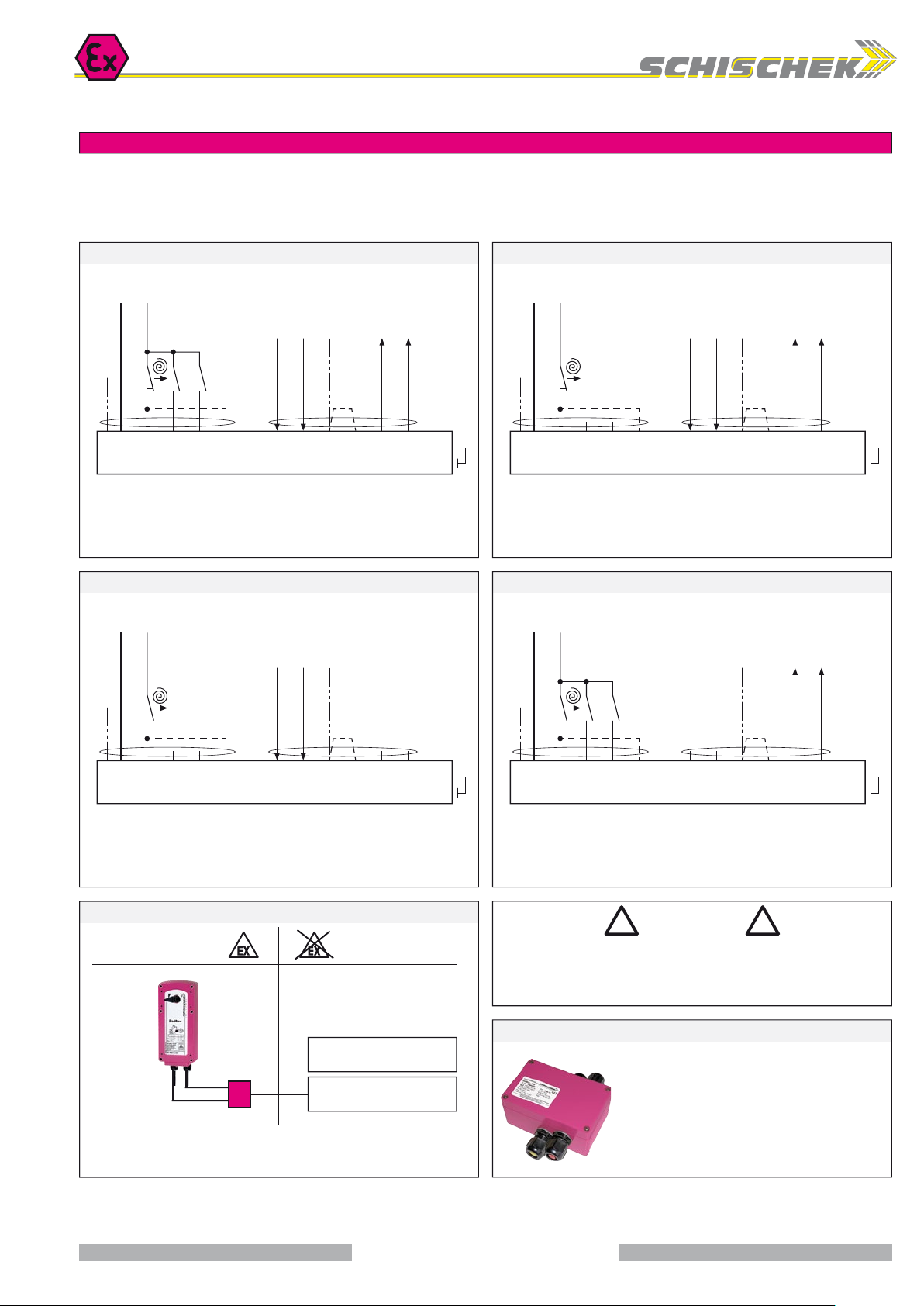
Electrical connection
All actuators are equipped with a universal supply unit working at a voltage range from
24...240 VAC/DC. The supply unit is self adjusting to the connected voltage!
The safety operation of the spring return function works if the supply voltage is cut.
For electrical connection inside hazardous areas a terminal box is required (e.g. RedBox).
An over-current protection fuse < 10 A has to be provided by installer.
Note: the initial current is appr. 2 A for 1 second.
Modulating / 3-pos. – with / without spring return SB 5.0 Modulating – with / without spring return (no enforcement) SB 5.1
24...240 VAC/ DC 24...240 VAC/ DC
+
−
~
~
Self adjustment:
To adjust the signal input/ output to the angle of
rotation of the damper/ valve the button (T) must
be pushed for a minimum of 3 sec.
Y
mA
T
Y
VDC
VDC/mA
U
U
mA
VDC
+
−
~
~
Self adjustment:
To adjust the signal input/ output to the angle of
rotation of the damper/ valve the button (T) must
be pushed for a minimum of 3 sec.
Y
mA
T
Y
VDC
VDC/mA
U
U
mA
VDC
PE PE
1 1
2 2
Selection of running time for spring return:
Spring return in ~ 10 s = Standard wiring
Spring return in ~ 3 s = Additional wiring on terminal 5
Function and enforcement control of switch a and b in modulating mode:
▪ a closed – Forced-ON (OFF) in acc. to left/ right mounting of actuator
▪ b closed – Forced-OFF (ON) in acc. to left/ right mounting of actuator
b
3 3
5 5
4 4
1 1
2 2
3 3
4 4
Reverse function:
Bridge 3– 4 reverses the
input and output signals
6 6
5 5
PA PA
Selection of running time for spring return:
Spring return in ~ 10 s = Standard wiring
Spring return in ~ 3 s = Additional wiring on terminal 5
Reverse function:
Bridge 3– 4 reverses the
input and output signals
Modulating – with / without spring return (no feedback) SB 5.2 3-pos. – with / without spring return + feedback SB 5.3
24...240 VAC/ DC 24...240 VAC/ DC
+
−
~
~
Self adjustment:
To adjust the signal input/ output to the angle of
rotation of the damper/ valve the button (T) must
be pushed for a minimum of 3 sec.
Y
mA
T
Y
VDC
VDC/mA
+
−
~
~
PE PE
1 1
2 2
3 3
Selection of running time for spring return:
Spring return in ~ 10 s = Standard wiring
Spring return in ~ 3 s = Additional wiring on terminal 5
5 5
4 4
1 1
2 2
3 3
4 4
Reverse function:
Bridge 3– 4 reverses
the input signals
6 6
5 5
PA PA
Selection of running time for spring return:
Spring return in ~ 10 s = Standard wiring
Spring return in ~ 3 s = Additional wiring on terminal 5
3-pos. control mode:
▪ a closed, b open – ON (OFF) in acc. to left/ right mounting of actuator
▪ b closed, a open – OFF (ON) in acc. to left/ right mounting of actuator
aab
Self adjustment:
To adjust the signal input/ output to the angle of
rotation of the damper/ valve the button (T) must
be pushed for a minimum of 3 sec.
Attention!
When changing 3-position
mode into modulating
regard function, see
page 4 – Parametrisation D)
T
U
VDC/mA
Reverse function:
Bridge 3– 4 reverses
the output signals
mA
U
VDC
Installation
! !
Ex area –
zone 2, 22
Safe area
During commissioning apply a self adjustment drive.
Attention
Regard duty cycle at motor running times!
Never use spring return actuators without external load.
Accessory RedBox – adaptable terminal box
Y: 0...10 V / 4...20 mA
U: 0...10 V / 4...20 mA
supply *
24...240 VAC/DC ± 10 %
RedBox
* electrical wiring see diagrams
For electrical connection of ...Max actuators inside the
hazardous area an Ex-e terminal box is required.
RedBoxes are appropriate terminal boxes and placed at
the disposal. To adapt the ...Box directly to the actuator
housing a mounting bracket type MKK-S is required.
RedBox- Y/S for ...Max-...-Y and ...-YF with integral
auxiliary switches
3 / 4
Page 4
EXPLOSIONPROOF
www.schischek.com
Schischek GmbH Germany, Muehlsteig 45, Gewerbegebiet Sued 5, 90579 Langenzenn, Tel. +49 9101 9081-0, Fax +49 9101 9081-77, E-Mail [email protected]
RedMax-S-Y_en
V01 – 20-Apr-2016
RedMax-...-Y RedMax-...-YF
Special options ... -CTS ... -VAS
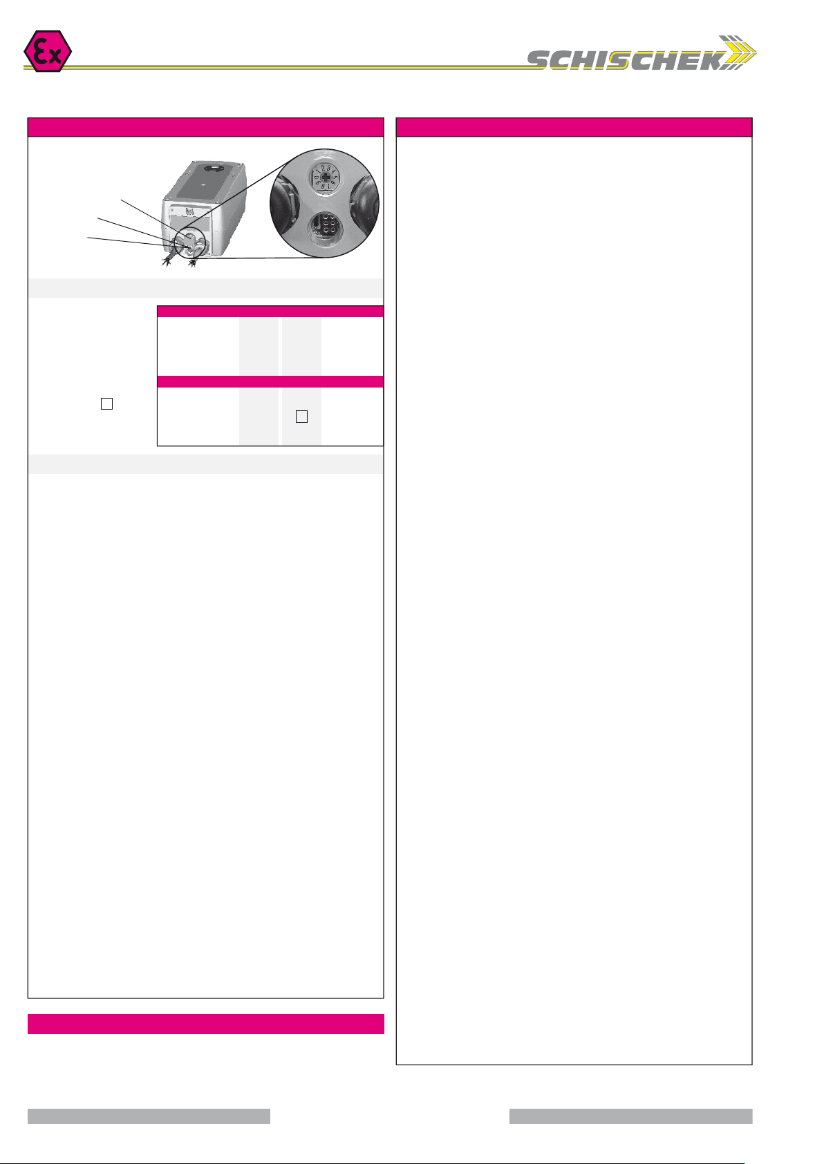
Parameters, adjustments and failure indication
Switch – Push button – Lamp
for adjustment
(behind the blanking plug)
S
10-position switch (S)
Push button (T)
3-colour LED
T
Parameter selection
Example:
RedMax-15.30-Y
Requested parameter:
Torque 30 N
Motor running time 30 s/90°
Result:
Switch position 07
Type
RedMax- 5.10-Y ►
RedMax- 15.30-Y ►
RedMax- 5.10-YF ►
RedMax- .
Running times Position of switch S
7,5 s/90° ►
15 s/90° ►
30 s /90° ►
60 s/90° ►
120 s/ 90° ►
15-YF ►
5 N
15 N
5 N
15 N
▼
00
01
02
03
04
Torques
10 N
30 N
10 N
▼
05
06
07
08
09
Functions, adjustments and parameters
A) Self adjustment of angle of rotation:
Switch (S) into position 02 (low torque) or 07 (high torque), then push button (T) for
minimum 3 seconds. The actuator will drive into both end positions to be adjusted.
LED indicates GREEN.
Adjustment time needs approx. 60 sec. (30 sec. “On”, 30 sec. “Off”). After that, switch
(S) into the position acc. with your required torque and running time.
B) Selection of running time and torque:
Put switch (S) into the correct selected position in acc. to above table.
The selected parameter will work at next operation of the actuator.
Adjustment can be done even without supply voltage. If supply voltage
is available turn switch only if actuator is not running.
C) Running time spring return:
The running time of 3 or 10 sec. spring return is selected by wiring (see diagrams).
D) Changing modulating mode into 3-pos. operation mode with feedback:
Push button (T) 3 times.
LED changes from permanent GREEN to permanent YELLOW.
Push button within following limits:
▪ Push for min. 0,2 sec. each
▪ Complete pushing (3 ×) within 5 sec.
LED – Status:
▪ GREEN (permanent) – Supply available, actuator is active in modulating mode
▪ YELLOW (permanent) – Supply available, actuator is active in 3-pos. (+ U) mode
E) Changing 3-pos. mode with feedback into modulating operation mode:
Push button (T) 3 ×. LED changes from permanent YELLOW to permanent GREEN.
F) Additional information for 3-pos. operation:
a closed, b open = direction I
b closed, a open = direction II
a and b closed = motor doesn’t work
a and b open = motor doesn’t work
The rotation direction (I and II) depends on left/right mounting of the actuator to the
damper/valve. You can change direction of the motor by changing electrical wiring
of terminal 3 and 4.
G) Reverse function:
Bridge between signal wise wiring 3–4 (cable B) gets a reverse function of input Y
and feedback signals U.
Extra information (see additional data sheet)
Additional technical information, dimensions, installation instruction, illustration
and failure indication
Important information for installation and operation
A. Installation, commissioning, maintenance
All national and international standards, rules and regulations for hazardous Ex-areas
must be complied. Certified apparatus must be installed in accordance with manufacturer
instructions. If the equipment is used in a manner not specified by the manufacturer,
the safety protection provided by the equipment may be impaired. For electrical
installations design, selection and erection, EN/IEC 60079-14 can be used.
For electrical connection an Ex-e terminal box is required (e.g. RedBox-...).
Attention: If the actuator is put out of operation all Ex rules and regulations must be
applied. You have to cut the supply voltage before opening the terminal box!
The cables of the actuator must be installed in a fixed position and protected against
mechanical and thermical damage. Connect potential earth. Avoid temperature transfer
from armature to actuator! Close all openings with min. IP66. For outdoor installation
a protective weather shield against sun, rain and snow should be applied to the actuator
as well as a constant supply at terminal 1 and 2 for the integral heater.
Actuators are maintenance free. An annual inspection is recommended. For electrical
installations inspection and maintenance, EN/IEC 60079-17 can be used. Ex-actuators must not be opened by the customer.
B. Manual override
Manual override only if supply voltage is cut. Use delivered socket wrench with slow
motions, usage can be tight. Attention: Releasing or letting go the Allen key too fast
at manual operating actuators with spring return causes risk of injury!
C. Shaft connection, selection of running time
Actuators are equipped with a direct coupling double square shaft connection of
12 × 12 mm. For round shafts adaptors/clamping connection (accessories, e.g. KB-S)
are available. The housing of the actuator is axially symmetrically built to select Open-close
direction of the spring return function by left-right mounting. Using the 10-position switch
different motor running times and spring return running times can be selected on site
in acc. to the actuator type.
D. 3-position control mode
...Max actuators are in the best way suitable for the 3-pos. operation. To protect such
elements as gears and mounting elements against harmful influences like minimum
pulse time, ...Max actuators are protected via internal electronics. It ignores impulses
< 0.5 s, the cyclic duration must be min. 0.5 s. At changing direction the pause is 1 s.
E. Spring return
Spring return function works only if the supply voltage for terminal 1 or 2 is cut. In the
event of an electrical interruption, the spring returns to its end position even if supply
voltage is available again during return function. Thereafter operation will continue.
F. Operation at ambient temperatures below −20 °C
All actuators are equipped with a regulated integrated heating device designed for
employments down to −40 °C ambient temperature. The heater will be supplied
automatically by connecting the constant voltage supply on the clamps 1 and 2.
1. After mounting the actuator must bei immediately electrically connected.
2. The heater switches on automatically when actuator reaches internally −20 °C. It
heats up the actuator to a proper working temperature, then heater switches off automatically. Actuator will not run during heating process.
3. The adjustment options are only ensured after this heating up period.
G. Excess temperatures
In acc. to the ATEX rules and regulations Ex actuators must be protected against excess
temperature. The internal thermostat works as a maximum limiter and, in the event of
failure at incorrect temperatures, shuts off the actuator irreversible. An upstream
connected temperature sensor stops the actuator before reaching its max. temperature.
This safety feature is reversible, after cooling down the actuator is completely functional
again. In this case the failure must be eliminated immediately on site!
H. Synchron mode
Do not connect several actuators to one shaft or link mechanically together.
I. Mechanical protection
The actuator must be operated with an outside load of at least 3 Nm.
After installing the actuator to the damper/armature an automatic alignment has to be
accomplished in order to obtain a “gentle” blockade/stop. This function protects the
damper/armature by reducing the end position’s/blockade speed in order to avoid
mechanical overload. The actuator alignes specifically once with 30 s/90° onto each
position and recognizes the blockade position in order to reduce the motor performance
during operation briefly before reaching the end/blockade position.
J. Intrinsically safe circuits
The supply of the push button (adjustment drive), the 10-position switch (adjustment
of torque and running time) and the LED indicator is performed intrinsically safe!
4 / 4
 Loading...