

Page 1
Schischek GmbH Germany, Mühlsteig 45, Gewerbegebiet Süd 5, 90579 Langenzenn, Tel. +49 9101 9081-0, Fax +49 9101 9081-77, E-Mail [email protected]
www.schischek.com
EXPLOSIONPROOF
InBin-P Pressure switches from 5 Pa...100 Pa
D.IB-P100-02.01-en
23-Aug-2012
InBin - P-100
InBin - P-100 - CT
Electrical, binary pressure or differential pressure switches
with adjustable switch activation delay
InBin - P-100 - OCT
Subject to change!
24 VAC/DC supply voltage, output potential free switching contact
Compact. Easy installation. Universal. Cost effective. Safe.
Type Sensor Supply Range Min. setting Max. pressure Output switch Max. ratings Wiring diagram
InBin - P-100 Pressure 24 VAC/DC 0...100 Pa 5 Pa 5.000 Pa pot. free contact 250 VAC, 0,1 A / 30 V, 0,5 A SB 1.0
InBin - P-100 - CT as above with aluminium housing and Amercoat painting (sensor connection and cable glands nickel-plated, screws in stainless steel)
InBin - P-100 - OCT as above offshore version seawater-resistant, with aluminium housing and Amercoat painting (stainless steel tubes for clamping ring connection,
cable glands M20 × 1,5 mm nickel-plated, screws in stainless steel)
Application
Pressure or ∆ pressure switch
Amercoat version ...-CT
Offshore version ...-OCT
Description
The InBin-P-100 pressure switch generation from 5...100 Pa is a revolution
for differential pressure switches in HVAC systems, in chemical, pharmaceutical, industrial and Offshore-/Onshore plants.
IP66 protection, small dimension, universal functions and technical data
guarantee safe operation even under difficult environmental conditions.
The switching point is scalable within the maximum ranges. The integrated
display is for actual value indication which can be switched off.
All sensors are programmable on site without any additional tools.
InBin-P-100-OCT is equipped with stainless steel 316L tubing Ø 6 mm.
Highlights
►
For industrial use
►
Integrated junction box
►
Power supply 24 VAC/DC
►
Output potential free switching contact
►
Display with backlight, can be switched off
►
Adjustable switching characteristics
►
Adjustable hysteresis
►
Adjustable starting bypass time
►
Adjustable switch activation delay
►
Compact design and small dimension (L × B × H = 180 × 107 × 66 mm)
►
Robust aluminium housing in protection class IP66
►
Down to −20°C ambient temperature applicable
►
Password locking
►
CT versions have an excellent resistance to chemicals and seawater
►
OCT as CT version plus pressure tube connection for clamping ring Ø 6 mm
1 / 6
Page 2
Schischek GmbH Germany, Mühlsteig 45, Gewerbegebiet Süd 5, 90579 Langenzenn, Tel. +49 9101 9081-0, Fax +49 9101 9081-77, E-Mail [email protected]
www.schischek.com
EXPLOSIONPROOF
Technical data
InBin-P-100
D.IB-P100-02.01-en
23-Aug-2012
Power supply 24 VAC/DC ± 20% (19,2…28,8 VAC/DC) 50…60 Hz
Current, power consumption 150 mA, ~ 4 W, internal fuse 500 mAT, without bracket, not removable
Galvanic isolation Supply – output 1,5 kV
Electrical connection Terminals 0,14…2,5 mm² at integrated junction box, stripping length 9 mm, torque 0,4…0,5 Nm
Cable entry 2 × M16 × 1,5 mm, cable diameter ~ Ø 5…10 mm (...-CT in nickel-plated)
Cable entry ...-OCT 2 × M20 × 1,5 mm, cable diameter ~ Ø 6…13 mm (...-OCT in nickel-plated)
Display LCD with backlight, display for configuration, user guidance, parameter and actual value indication via LEDs
Control elements 3 buttons for configuration
Housing protection IP66 in acc. to IEC 60529
Housing material Aluminium casting, coated (...-CT/...-OCT = version in Amercoat marine painting, seawater-resistant ...-OCT = Offshore version)
Dimension / weight L × W × H = 180 × 107 × 66 mm / ~ 950 g
Ambient temperature/-humidity −20…+50 °C / 0…95 % rH, non condensed
Storage temperature −40…+70 °C
Measuring range 0…100 Pa
Range scalable on site
Maintenance Maintenance free, nevertheless maintenance must be complied with regional standards, rules and regulations
Sensor circuit Internal circuit
Sensor Piezo-pressure-transmitter
Pressure connection P+ / P− sleeves Ø 4…6 mm, OCT-version has a Ø 6 mm stainless steel tube connection for clamp ring fittings
Response time of sensor T90 / 5 sec.
Accuracy of pressure < ± 1 % typically, max. ± 5 % of end value ± 1 Pa
Setting range hysteresis 0,1 Pa…10 Pa (factory setting 2 Pa)
Start delay 5 sec.
Starting bypass time 3…240 sec. (via menu adjustable; preset 120 sec.)
Switch activation delay 0...240 sec. (via menu adjustable; preset 0 sec./Off)
Setting zero point Via menu, mechanical short circuit of P+ / P− for the moment of zero point setting
Output switch Potentail free switching contact
Ratings load max. 0,5 A at 30 VAC/DC / 0,1 A at 250 VAC / 0,1 A at 220 VDC
Ratings load min. 10 mW / 0,1 V / 1 mA
Mechanical life 10 × 10
Electrical life (rated load) 100 × 10
Wiring diagram (SB) SB 1.0
Installation sensor / tubing Safe area
Minimum measuring range is 5 % of full range = 5 Pa
6
3
Approbations
CE-Mark CE No. 0158
EMC directive 2004/108/EC
Low voltage directive 2006/95/EC
Protection type IP66 in acc. to EN 60529
Potential compensation external PA-terminal, 4 mm²
Protection Class Class I (grounded),
overload voltage category II acc. EN 61010-1
Accessories
MKR Mounting bracket for round ducts up to Ø 600 mm
Kit 2 Consists of 2 m flexible pressure tube Ø 6 mm, 2 connection nipples
Kit PTC consisting of 2 connecting tubes Ø 6 mm for tube fittings
2 / 6
Page 3
Schischek GmbH Germany, Mühlsteig 45, Gewerbegebiet Süd 5, 90579 Langenzenn, Tel. +49 9101 9081-0, Fax +49 9101 9081-77, E-Mail [email protected]
www.schischek.com
EXPLOSIONPROOF
Electrical connection
InBin-P-100
D.IB-P100-02.01-en
23-Aug-2012
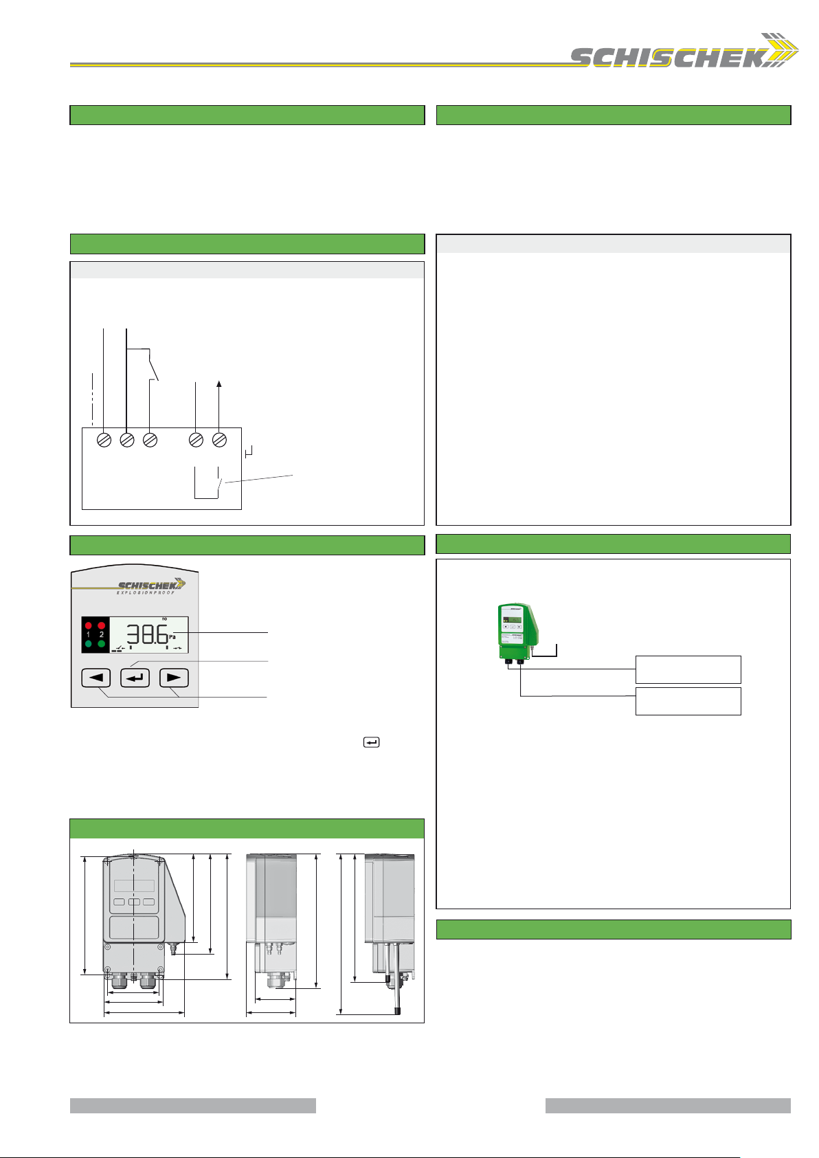
InBin-P-100 switches are equipped with a 24 VAC/DC power supply. The supply has to
be connected at terminal 1 (−/~) and 2 (+/~). The electrical wiring must be realized via
integrated junction box.
If supply voltage 24 VAC/DC differs from the relay voltage different or double isolated cables
must be used.The starting bypass delay can be activated by a short circuit of terminal 2
and teminal 3 (AUB). An active bypass delay is indicated with green blinking LEDs.
Attention: Do not open covers when circuits are alive!
Password input
The default / delivery setup is 0000. In this configuration the password input is not activated.
To activate a password change the 4 digits into your chosen numbers (e.g. 1234) and press
Enter. Please keep your password in mind for next parameter change!
Due to a new parameter setup the password is requested.
Wiring diagram InBin-P-100
InBin-P-100
24 VAC/DC
+
−
~
~
PE
1 2 3 4
Relay output
250 VAC 0,1 A / 220 VDC 0,1 A
30 VAC/DC / 0,5 A
SW-Ch1
SW-IN (GND)
AUB
5 6
PA
If supply voltage 24 VAC/DC
differs from the relay voltage
different or double isolated
cables must be used.
function normal close (nc) or
normal open (no) can be
selected via menu
SB 1.0
Display and buttons
Display for
programming and
indication
Push button
ENTER
Push button
for level select
Change operation-/parametrisation mode
To change from operation to parametrisation mode push the enter button for
minimum 3 seconds. Back over the menu save.
Indication of data logging
A blinking unit in the display shows that data is received and the device is working.
Dimensions/ drillings
Dimensions in mm
117
132
157,5
67
80
107
166
55
66
~ 180
170
213
Important information for installation and operation
A. Installation, commissioning, maintenance
The cable has to be drawn through the cable gland. After electrical connection the
cable gland must be fixed tighten. IP66 must be fulfilled. In acc. with operation InBin
switches are maintenance free. The sensors must not be opened by the customer.
For electrical connection use the internal junction box.
Attention: Before opening the internal junction box cut off the power supply.
B. Supply and Contact
Wires from safety extra low voltage must be separated from others. Only at 24 VAC/DC
supply and signal wires in one cable is permitted. All others use separate or double
isolated cables. Install overload protection fuse < 10 A.
C. Pressure sensors
After mounting and installation, a zero point compensation must be done, because
the offset value depends on the installation position. Have a look at parametrisation.
D. Long cabling
For using long signal wires, shielded cables are recommended. The shield must be
connected to the InBin-P switch inside the terminal box.
E. Separate ground wires
Use for supply and signal wires a separate ground.
Installation
Safe area
P+ P−
Supply
24 VAC/DC
Relay output
250 VAC/0,1 A 30 V/0,5 A
▪ Maintenance must comply with regional standards, rules and regulations
▪ Do not open covers when circuits are alive
▪ For electrical connection use the integrated junction box
▪ The cable must be installed in a fixed position and protected against mechanical
and thermical damage
▪ Connect protection earth
▪ Avoid thermal transfer from sensor probe to transducer (ensure max. ambient temperature).
▪ Ambient temperature −20…+50 °C
▪ Close all covers, entries with min. IP66
▪ All transducers are maintenance free
▪ For outdoor installation a protective housing against rain, snow and sun should be applied
▪ Only wet cleaning
Zero point compensation for pressure transmitter
For a InBin-P-100 pressure switch installation a zero point compensation should be
performed to adjust value deviations of the module‘s installation position. Therefore the
pressure nipples P+ / P− must be connected with a short circuit tube and the zero point
compensation accomplished by following the menu.
Before starting the compensation the device should be connected to the power supply for
minimum of 15 minutes to reach the working temperature!
3 / 6
Page 4
Schischek GmbH Germany, Mühlsteig 45, Gewerbegebiet Süd 5, 90579 Langenzenn, Tel. +49 9101 9081-0, Fax +49 9101 9081-77, E-Mail [email protected]
www.schischek.com
EXPLOSIONPROOF
Parametrisation and commissioning of InBin-P-100 transducers
D.IB-P100-02.01-en
23-Aug-2012
InBin-P-100
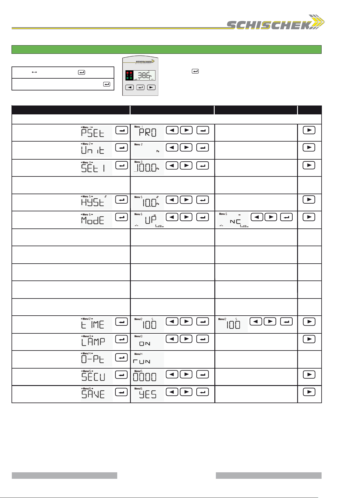
Change operation-/parametrisation modePreparation of parametrisation/operation
To change from operation to parametrisation mode push
Parametrisation, push for 3 sec.
Operation
If password (PW) protection is active: put PW in, push
Menu IndicationFunction Select Enter Next selectionEnter Next menuNext indication Enter
Menu 1
Preset
select application
Menu 2
unit sensor 1
select physical unit
Menu 3 set 1
select switching
point 1
Menu 4 no function – menu skip
Menu 5 hysteresis*
select physical unit
Menu 6 mode*
select switching
charateristic
no function – menu skip
Menu 7
„Enter button“ for minimum 3 seconds. Back over the
menu save.
Pa, mBar, InH2O
adjust set 1
adjust hysteresis
norm. open (no), norm. closed (nc)
select normal sensor interval
Menu 8
no function – menu skip
no function – menu skip
Menu 9
no function – menu skip
Menu 10
no function – menu skip
Menu 11
Menu 12
time select time for
starting bypass (AUB) and
switch activation delay
Menü 13
lamp
select backlight
zero point compensation
Menu 14
Menu 15
security
select password
save
Menu 16
select save data
* Useable in professional mode only (see Menu 1 – professional mode)
** Bypass delay
*** Switch activation delay:
With this function the condition „normal operation“can be hold for the selected time.
Setting the switching off delay to „0“ will deactive the function.
adjust bypass time**
on, off
enter password
no, yes, return, default setting
adjust switching off delay***
4 / 6
Page 5
Schischek GmbH Germany, Mühlsteig 45, Gewerbegebiet Süd 5, 90579 Langenzenn, Tel. +49 9101 9081-0, Fax +49 9101 9081-77, E-Mail [email protected]
www.schischek.com
EXPLOSIONPROOF
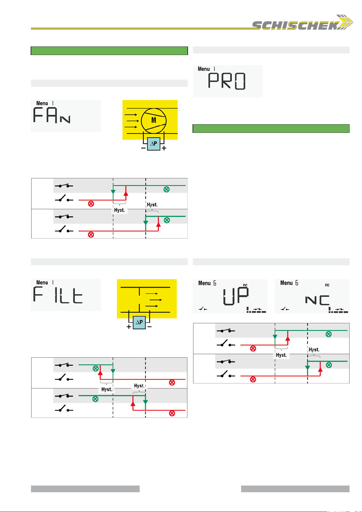
Using the menu 1 „Preset“
InBin-P-100
D.IB-P100-02.01-en
23-Aug-2012
To beware complexity during the parametrisation process, the InBin-P has several predefined
setups which distinguish between its intended application.
You'll find a detailed desciption of all possible presets in the following section.
Fan speed monitoring
The preset „FAN“ is designed for use in fan speed monitoring applications.
Professional mode
For all other applications the professional mode is designed for.
Menu1: Select „PRO“ and press the
enter button.
ventilator
air flow
Menu1: Select "FAN" and press the
enter button.
If the „FAN“-preset has been selected in menu 1, all settings were made as the
following ones:
setpoint 1
state
setpoint 2
normal
green
output
switch 1
state
output
red
normal
green
switch 2
(optional)
The user has not to set the menu 5 „hysteresis“ and menu 6 „mode“, this will be done via
software. These menus will be skipped during the further parametrisation process.
red
Filter monitoring
The preset „FILT“ is designed for use in filter monitoring applications.
If the „PRO“-preset has been selected in menu 1, the parametrisation procedure will be
added by two further menus: menu 5 „hysteresis“ and menu 6 „mode“. For this preset the
user has to select the values for the hysteresis and for the mode.
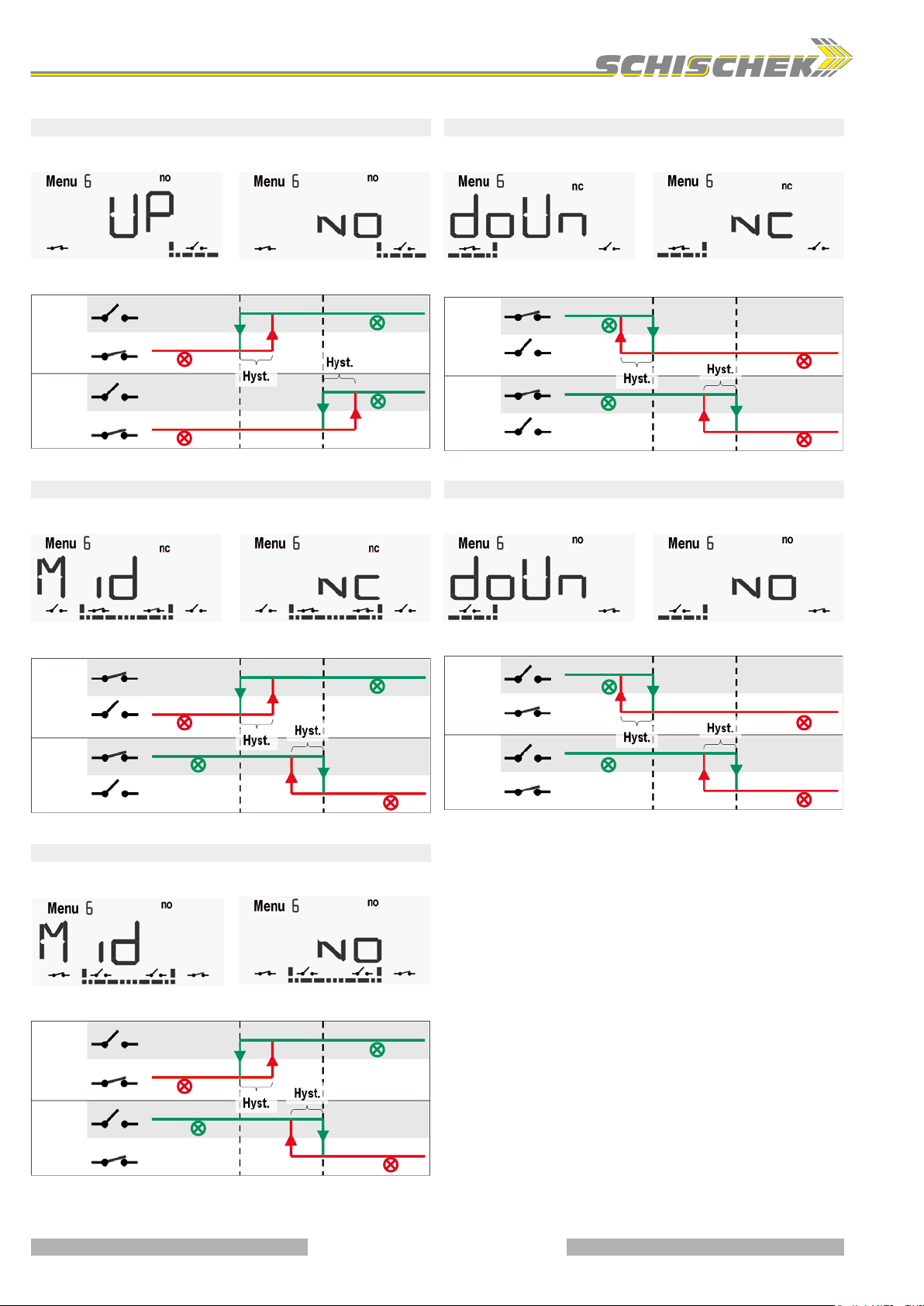
Using the menu 6 „mode“
First of all the user has to define the device normal range. For example:
- The device should indicate (green LED) if the pressure is under the setpoints, mode
„down-range“ has to be selected. With other words: the measure value is normally
under the setpoints.
- The device should indicate (green LED) if the pressure is over the setpoints, mode
„up-range“ has to be selected. (The measure value is normally over the setpoints.)
- The device should indicate (green LED) if the pressure is between the setpoints, mode
„mid-range“ has to be selected. (The measure value is normally between the
setpoints). This mode is only for 2-stage devices available (InBin-P...-2).
In the second step the switching characteristic of the output relay has to be selected:
- „normally closed“ (nc): if the measure value is in the normal range (see above), the
corresponding relays were closed.
- „normally open“ (no): if the measure value is in the normal range (see above), the
corresponding relays were open.
You'll find a detailed desciption of all possible settings in the following section.
Switching characteristic „up-range“ – „normally closed“
„Up-range“: the normal range is above setpoint 1 and setpoint 2
Filter
Air flow
Menu1: Select „FILT“ and press the
enter button.
If the „FILT“-preset has been selected in menu 1, all settings were made as the following
ones:
setpoint 2
state
setpoint 1
normal
green
output
switch 1
state
output
normal
green
red
switch 2
(optional)
The user has not to set the menu 5 „hysteresis“ and menu 6 „mode“, this will be done via
software. These menus will be skipped during the further parametrisation process.
red
state
output
switch 1
state
output
switch 2
(optional)
red
red
setpoint 1
setpoint 2
normal
green
normal
green
5 / 6
Page 6
Schischek GmbH Germany, Mühlsteig 45, Gewerbegebiet Süd 5, 90579 Langenzenn, Tel. +49 9101 9081-0, Fax +49 9101 9081-77, E-Mail [email protected]
www.schischek.com
EXPLOSIONPROOF
D.IB-P100-02.01-en
23-Aug-2012
Switching characteristic „up-range“ – „normally open“
InBin-P-100
„Up-range“: the normal range is above setpoint 1 and setpoint 2
Switching characteristic „down-range“ – „normally closed“
„Mid-range“: the normal range is under setpoint 1 and setpoint 2
setpoint 2
normal
green
normal
green
state
output
switch 1
state
output
switch 2
(optional)
setpoint 1
red
red
Switching characteristic „mid-range“ – „normally closed“
„Mid-range“: the normal range is between setpoint 1 and setpoint 2 (for 2-stage devices only)
setpoint 2
normal
green
red
state
output
switch 1
state
output
switch 2
(optional)
setpoint 1
red
normal
green
setpoint 2
state
output
switch 1
state
output
switch 2
(optional)
setpoint 1
normal
green
normal
green
Switching characteristic „down-range“ – „normally closed“
„Mid-range“: the normal range is under setpoint 1 and setpoint 2
state
output
switch 1
state
output
switch 2
(optional)
setpoint 1
normal
green
normal
green
setpoint 2
red
red
red
red
Switching characteristic „mid-range“ – „normally open“
„Mid-range“: the normal range is between setpoint 1 and setpoint 2 (for 2-stage devices only)
setpoint 1
state
output
switch 1
state
output
switch 2
(optional)
red
normal
green
setpoint 2
normal
green
red
6 / 6
 Loading...