


Schindler Elevator Ltd
Switzerland
Schindler Elevators Ltd
Zugerstrasse 13
CH-6030 Ebikon
Schweiz
Tel. +41 41 445 31 31
Fax +41 41 445 39 11
www.schindler.com
We, Schindler elevators Ltd
Zugerstrasse 13, CH-6030 EBIKON, Switzerland
USER MANUAL
Features
24 GHz K-band miniature transceiver
180MHz sweep FM input (n.a. for K-LC1a_V2)
Dual 4 patch antenna
Single balanced mixer with 50MHz bandwidth
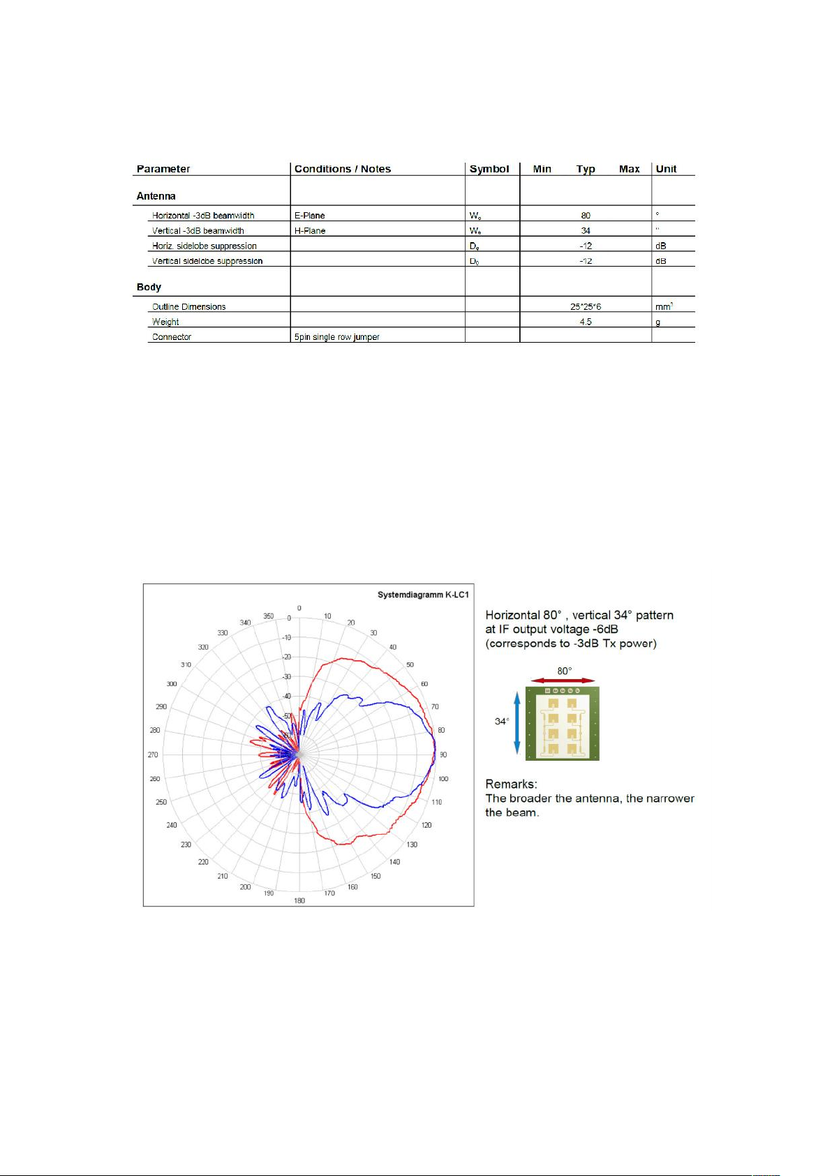
Beam aperture 80°/34°
15dBm EIRP output power
25x25mm2 surface, 6mm thickness
Lowcost design
3 pin version K-LC1a_V2 available
Applications
General purpose movement detectors
Security systems
Object speed measurement systems
Simple shortrange ranging detection
Highspeed shortrange data transmission
Industrial sensors
K-LC1 RADAR TRANSCEIVER
Description
K-LC1a is a 8 patch Doppler module with an asymmetrical beam for lowcost short distance
applications. Its typical applications are movement sensors in the security and automatic door
domain. In building automation this module may be an alternative for infrared PIR or AIR
systems thanks to its outstanding performance/cost ratio.
The module is extremely small and lightweight.
With its IF bandwidth from DC to 50MHz it opens many new applications.
FSK is possible thanks to the unique RFbeam oscillator design. This allows to use this
lowcost module even in ranging applications.
Powerful starterkits with signal conditioning and visualization is available from RFbeam.
Find more informations at www.rfbeam.ch.
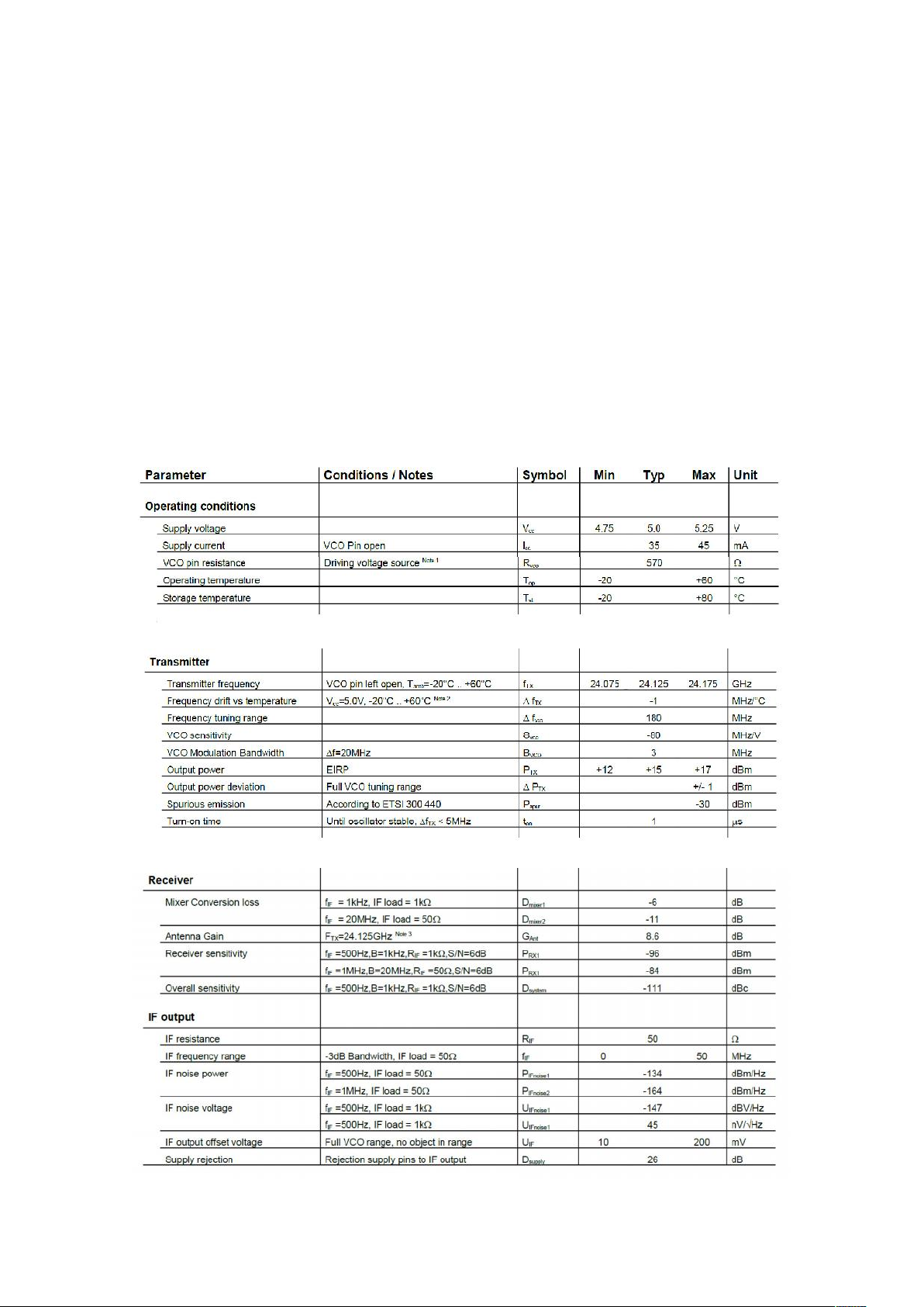
Characteristics
Note 1: The VCP input has an internal voltage source with approx. 0.9 VDC. For driving this pin it is necessary to source and sink
current.
Note 2: Transmit frequency stays within 24.075 to 24.175GHz over specified temperature range when the VCO pin is left open
Note 3: Theoretical value, given by design.
On this module the connector pin for the modulation input is not present. So this low-impedance
input is always not connected, what is the best case. So there will never be any 'unwanted'
modulation
Antenna System Diagram
This diagram shows module sensitivity in both azimuth and elevation directions. It incorporates
the transmitter and receiver antenna characteristics.

FM Characteristics
VCO Voltage generates an output signal even without an object in range because of the finite
isolation between transmitter and receiver path. This effect is called self-mixing and leads to a
DC signal that depends on the carrier frequency / the VCO voltage.

ASSEMBLY INFORMATION
Features
The radar module is mounted on a card reader pcb board and locked by a plastic support clip.
Assembly Diagram
Step 1: Place the plastic support on the Card reader board PCB.
Step 2: Insert the radar module into base board radar connector.
Radar Module
Plastic support clip
Base board

Step 3: Close the support clip locker
Step 4: Place the card reader with radar inside your Port device
For example:

NOTE: The marking label oft he host appliance of the present radar module must
contains the following inscription:
“Contains FCC ID: XFIPORTRADARVER1”
Application Notes
Sensitivity and Maximum Range
The values indicated here are intended to give you a 'feeling' of the attainable detection range
with this module. It is not possible to define an exact RCS (radar cross section) value of real
objects because reflectivity depends on many parameters.
Please note, that range values also highly depend on the performance of signal processing,
environment conditions (i.e. rain, fog), housing of the module and other factors.
For simple detection purposes (security applications e.g.) without the need of speed
measurements, range may be enhanced by further reducing the IF bandwidth. With 250Hz
bandwidth and a simple comparator, we get already a 25m detection range.
FCC in formations:
This device complies with part 15 of the FCC Rules. Operation is subject to the following two conditions:
(1) This device may not cause harmful interference, and
(2) this device must accept any interference received, including interference that may cause undesired
operation.
Changes or modifications not expressly approved by the manufacturer could void the user’s
authority to operate the equipment
This equipment has been tested and found to comply with the limits for a Class B digital device, pursuant
to part 15 of the FCC Rules. These limits are designed to provide reasonable protection against harmful
interference in a residential installation. This equipment generates, uses and can radiate radio frequency

energy and, if not installed and used in accordance with the instructions, may cause harmful interference
to radio communications. However, there is no guarantee that interference will not occur in a particular
installation. If this equipment does cause harmful interference to radio or television reception, which can be
determined by turning the equipment off and on, the user is encouraged to try to correct the interference
by one or more of the following measures:
—Reorient or relocate the receiving antenna.
—Increase the separation between the equipment and receiver.
—Connect the equipment into an outlet on a circuit different from that to which the receiver is connected.
—Consult the dealer or an experienced radio/TV technician for help.
FCC ID : XFIPORTRADARVER1
 Loading...