

Schick USBcam4 User Manual
USBcam4 User Guide
B1051082
Sirona Dental, Inc.
30-30 47th Avenue, Suite 500
Long Island City, NY 11101
USA
(718) 937-5765
(718) 937-5962 (fax)
Sirona Dental Systems GmbH
Fabrikstr. 31
D-64625, Bensheim
Germany
PART NUMBER B1051082 REV. 3

Sirona Dental, Inc. products are covered by one or more US
Copyright 2016 by Sirona Dental, Inc.
All Rights Reserved
patents. For a current listing, please type Patent Notice into
the Search box of the Schick by Sirona website or enter the
following page information into your browser’s address bar.
http://www.schickbysirona.com/items.php?itemid=13112
September 27, 2016
Printed in the United States of America
This document was originally prepared in English

i
Contents
1. Overview ........................................................................................ 1
1.1. Purpose ...................................................................................................................................... 1
1.2. Indications for Use .................................................................................................................... 1
1.3. System Description ................................................................................................................... 2
1.4. Getting the Best Images with USBcam4 ................................................................................... 3
2. Installation ..................................................................................... 4
2.1. What You Will Need to Complete this Section ........................................................................ 4
2.2. Before You Start Installing Software ........................................................................................ 4
2.3. Setup with Windows 7 .............................................................................................................. 5
2.4. Setup with Windows Vista ........................................................................................................ 7
2.5. Setup with Windows XP ........................................................................................................... 9
2.6. Connecting the USBcam4 ....................................................................................................... 11
2.7. Installing the USBcam4 Handpiece Holder ............................................................................ 13
3. Operation ..................................................................................... 15
3.1. Operating the Camera .............................................................................................................. 15
3.2. Using Camera Sheaths ............................................................................................................ 19
3.3. Using the Camera with CDR DICOM .................................................................................... 20
3.4. Acquiring Video Images with the Footpedal .......................................................................... 23
3.5. Acquiring Video Images with Keyboard Shortcuts ................................................................ 23
4. Controls ....................................................................................... 24
4.1. Controls on the USBcam4 ....................................................................................................... 24
5. Protective Measures .................................................................. 25
5.1. Sheaths .................................................................................................................................... 25
5.2. Cleaning and Disinfecting the Handpiece ............................................................................... 25
5.3. Recommended Disinfectant .................................................................................................... 26
5.4. Cleaning the Lens Surface ....................................................................................................... 26
5.5. Cleaning the Computer ............................................................................................................ 26
Appendix A. Reference Information ........................................... 27
A-1. Removal and Replacement Procedures ................................................................................... 27
A-2. Summary of Specifications ..................................................................................................... 27
A-3. Leakage Current Statement ..................................................................................................... 28
A-4. EMC Tables ............................................................................................................................ 28
Appendix B. Additional Information........................................... 32
B-1. Checking DirectX Version and Video Information ................................................................ 32
B-2. Checking Your Video Settings ................................................................................................ 32
Appendix C. Troubleshooting Tips ............................................ 36
C-1. Introduction ............................................................................................................................. 36
C-2. Troubleshooting Table ............................................................................................................ 36
Index ................................................................................................... 37
USBcam4 User Guide B1051082 Rev. 3

ii
List of Figures
Figure 1. USBCam4 Listed in Device Manager ............................................................................... 12
Figure 2. Handpiece Holder Instrument Rail Installation ................................................................. 13
Figure 3. Handpiece Holder Wall Mounting Installation ................................................................. 14
Figure 4. Video Capture Window ..................................................................................................... 16
Figure 5. Image Optimization ........................................................................................................... 19
Figure 6. USBcam4 Controls ............................................................................................................ 24
Figure 7. Video Setup Dialog Box .................................................................................................... 33
Figure 8. Camera Properties Dialog Box .......................................................................................... 34
Figure 9. Stream Format Dialog Box................................................................................................ 35
List of Tables
Table 1. USB Cable Description....................................................................................................... 11
Table 2. Footpedal Actions ............................................................................................................... 23
Table 3. Keyboard Shortcuts ............................................................................................................ 23
Table 4. Description of Camera Controls ......................................................................................... 24
Table 5. Specifications ...................................................................................................................... 27
Table 6. Guidance and Manufacturer's Declaration - Electromagnetic Emissions ........................... 28
Table 7. Guidance and Manufacturer's Declaration - Electromagnetic Immunity ........................... 29
Table 8. Recommended Separation Distance Between Portable and Mobile RF Communications
Equipment and the USBcam4 ............................................................................................ 31
Table 9. Video Setup Dialog Box Description ................................................................................. 33
Table 10. Camera Properties Dialog Box Description ...................................................................... 34
Table 11. Stream Format Dialog Box Description ........................................................................... 35
B1051082 Rev. 3 USBcam4 User Guide

iii
Safety Issues
Check USBcam4 before Using It
There are no customer-serviceable components in the USBcam4.
However, before each usage, check the outer surface of the
USBcam4 for any signs of p hysical damage or defect. The surface
of the USBcam4 should have a smooth finish, with no evidence of
chipping or damage to either the handpiece housing or the lens
section. If detected, contact your local distributor of Sirona Dental
products for further instructions.
To help ensure proper hygiene and to protect against infectious
disease, refer to Section 5 on page 25 and follow all cleaning and
patient protection recommendations specified there.
Avoid Excessive Temperatures when Using USBcam4
When in use, the LEDs in the USBcam4 may generate surface
temperatures in excess of 106° F (41° C). To avoid the potential risk
of burn, do not use the USBcam4 in a single hand-held position for a
prolonged period. As an additional safety measure, the USBcam4 is
equipped with an Auto-Off feature. Th is f eatu r e turns off the camer a
automatically after 5 minutes of continuous use. The camera can be
turned back on by simply pressing the ON/OFF button on the
handpiece.
Operate the USBcam4 as Directed
Always use the USBcam4 in accordance with the directions and
recommendations contained in this User Guide. Do not attempt to
modify the USBcam4 or use it in system configurations not
specified in this document.
RF Interference Considerations
Although the USBcam4 equipment is designed to provide a
reasonable degree of protection from electromagnetic interference,
according to IEC International regulations, it must be installed at an
adequate distance from electricity transformer rooms, static
continuity units, two-way amateur radios and cellular phones. To
ensure proper op eration, the latter (meani ng, electricity transform er
rooms, static continuity units, two-way amateur radi os and cellular
phones) can be used only at a minimum distance of 5 feet (1.5m)
from any part of the USBcam4 system.
Any instrumentation or equipment for professional use located near
USBcam4 must conform to Electromagnetic Compatibility
regulations. Non-conforming equipment, with known poor
immunity to electromagnetic fields, may not operate properly unless
USBcam4 User Guide B1051082 Rev. 3

iv
they are installed at a distance of at l east 10 feet (3m) and supplied
by a dedicated electric line.
Apply Recommended Procedures for Cleaning the Equipment
Safe and proper operation of the equipment requires that a regular
schedule of preventive maintenance be followed. Refer to the
Protective Measures section of this manual on page 25 for details.
Do Not Connect Items that are Not Part of the System
Only items specified for use with the equipment are to be connected
to the system. The equipment should not be used adjacent to other
equipment that is not part of the system. If, however, use with
adjacent equipment is necessary, normal operation should be
observed and verified in that configuration.
Installers to Ensure that USBcam4 Operates Optimally
Installers must ensure that the USBcam4 provides the user with the
optimal use of the equipment. This includes, but is not limited to,
ensuring the system operates as described in this document.
Installers must also ensure that the system presents no physical
obstacles or hazards during operation and when not in use. To verify
this requirement, installers shall confirm that the USBcam4 is
installed as described in this User Guide and shall perform the
appropriate procedures therein.
Ensure Proper System and PC Workstation Installation and Operation
The USBcam4 has been determined to be in accordance with
international safety standards and is deemed suitable for use within
the patient area, which extends from the patient for a distance of 5
feet (1.5m). To comply with these standards, do not operate nonmedical equipment (such as a PC workstation) inside the patient
area. Outside the patient area, the presence of app roved non-medical
grade equipment and Listed / Approved / certified Information
technology Equipment (ITE) computer equipment is acceptable.
The PC workstation that connects to the USBcam4 via compatible
USB cable is an integral part of a Medical Electrical System. The
PC must be a CE-approved computer system conforming with the
Low Voltage [73/23/EC] and EMC Directive [89/336/ERC]. Also,
to help ensure optimal performance, make sure that all
software programs residing on the workstation are virus-free
and have been adequately tested so they will not impact imaging
applications after installation.
Please refer to documentation provided by the PC manufacturer for
important information about its safe operation and usage.
B1051082 Rev. 3 USBcam4 User Guide

v
Observe Proper PC Workstation Cleaning Methods
To avoid cross contamination, be sure to follow the cleaning
instructions provided by your computer manufacturer and
implement them as part of your normal routine for ensuring proper
sterilization and disinfectant of tools in your dental practice.
Disconnect Camera from USB Cable before Cleaning and Disinfecting
Be sure to disconnect the camera from its USB cable before
performing the cleaning and disinfecting steps. When the procedure
is complete, make sure the camera is completely dry before
reconnecting it.
Always Use Sheaths with Sensors
Use Sirona Dental sh eaths every time the US Bcam4 is used. Never
use the intraoral camera without a protective sheath. Never use a
damaged sheath. Always dispose of the sheath after every patient.
Protective sheaths are single-use devices and must not be reused
under any circumstance. Reuse of single-use devices/instruments
may cause them to become contaminated, compromise their
intended function, and result in patient and user infection, injury
and/or illness.
Recommended Order for Connecting / Disconnecting Camera USB Cable
Connect the USB cable to the camera handpiece before connecting
the cable to the PC workstation. This will prevent an unintended
shock hazard caused by the patient contacting the powered USB
cable accidentally.
Disconnect the USB cable from the PC workstation before
disconnecting the cable from the camera handpiece. This will
prevent an unintended shock hazard caused by the patient contacting
the powered USB cable accidentally.
Product Manuals from Sirona Dental
The contents of this manual are subject to change without prior
notice. For the latest version of this user guide and other product
manuals from Sirona Dental, please consult our website:
www.schickbysirona.com.
USBcam4 User Guide B1051082 Rev. 3
vi
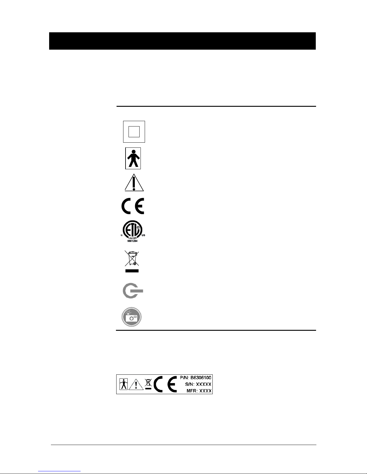
Symbol
Explanation of Symbols
Sirona Dental products display a number of marki ngs that indicate
compliance with regulatory requirements or that provide information
in accordance with applicable technical standards.
The symbols and their descriptions are provided below.
Description
Indicates Class II equipment in accordance with applicable
medical device safety standards (IEC/E N/U L 6060 1-1)
Indicates Type BF equipment in accordance with applicable
medical device safety standards (IEC/E N/U L 6060 1-1)
Indicates an attention to users to consult accompanying
documents (this User Guide) for more information
Conforms to European Union Medical Devices Directive (MDD)
93/42/EEC
Indicates that this product meets North American safety
standards. The ETL mark is a Nationally Recognized Testing
Lab (NRTL) marking and indicates conformance with UL 606011 and CAN/CSA STD C22.2 NO 601.1-M90
Indicates that in the European Union, at the end of product life
this device must be disposed of in accordance with the
requirements of the Waste Electrical and Electronic Equipment
(WEEE) directive 2002/96/EC
Indicates the location of the Power On / Off button on the
USBcam4 camera
Indicates the location of the Freeze Frame Capture button on the
USBcam4 camera
Label Location
The following label can be found on the USBcam4 camera.
B1051082 Rev. 3 USBcam4 User Guide
vii
W aste Electrical and Electronic Equipment
Background
The European Union’s Waste Electrical and Electronic Equipment
(WEEE) Directive (2002/96/EC) has been implemented in member
states as of August 13, 2005. This directive, which seeks to reduce
the waste of electrical and electronic equipment through re-use,
recycling, and recovery, imposes several requirements on producers.
Sirona Dental and its Dealers a re committed to complying with the
Directive.
WEEE Marking
All Sirona Dental products subject to the WEEE Directive and
shipped after August 13, 2005 will be compliant with the WEEE
marking requirements. These products will be identified with the
“crossed-out wheeled bin” WEEE symbol shown below, as defined
in European Standard EN 50419, and in accordance with WEEE
Directive 2002/96/EC.
Reporting
This “crossed-out wheeled bin” symbol on the product or on its
packaging indicates that this product must not be disposed of with
other unsorted municipal waste. Instead, it is user’s responsibility to
dispose of EE waste equipment by handing it over to a designated
collection point for the reuse or recycling of waste electrical and
electronic equipment . The separ ate collecti on and reuse o r recyclin g
of Electrical & Electronic waste equipment will help to conserve
natural resources and ensure that it is recycled in a manner that
protects the environment and human health. For more information
about where you can drop off your waste equipment for recycling,
please contact your local officials.
According to the WE EE Directive, Si rona Dental or its Dealers will
ensure that information needed to calculate the financial obligations
with respect to EEE products will be provided as required.
USBcam4 User Guide B1051082 Rev. 3

viii
WEEE from Users other than Private Households
According to the WE EE Directive, Si rona Dental or its Dealers will
fulfill its obligations for the management of WEEE from users other
than private households.
Furthermore, as required by the WEEE Directive, in order to
determine unequivocally when the equipment was put on the
market, the manufacturer’s date is placed on the equipment.
Information for Reuse Centers, Treatment and Recycling Facilities
As required by the WEEE Directive, Sirona Dental or its Dealers
will provide reuse, treatment, and recycling information for each
type of new EEE put on the market within one year of the date in
which the equipment is put on the market.
Information will include the different EEE components and
materials as well as the location of substances in these items. The
information will be provided as a printed document or in electronic
media (on CD-ROM or by web download, for example).
B1051082 Rev. 3 USBcam4 User Guide
ix
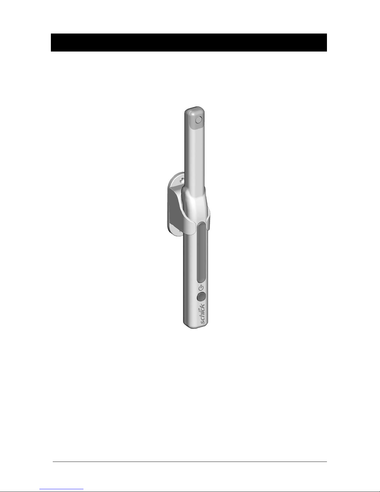
USBcam4
USBcam4 User Guide B1051082 Rev. 3
USBcam4 with Handpiece Holder

x
(This page is intentionally left blank)
B1051082 Rev. 3 USBcam4 User Guide

1
1. Overview
1.1. Purpose
An effective communication tool, USBcam4 (P/N B6306100)
supports streaming video and still frame capture to help dental
professionals demonstrate the current condition and post-treatment
outcomes of their patients’ dental health. Video frames can be
archived with dental exams as permanent records and r etrieved for
comparison or subsequent review.
Ergonomic, the USBcam4 provides slim, smooth contours and a
small head profile for comfortab le use and operation. Taking images
with the USBcam4 integrated capture button makes video frame
capture a simple o ne-pushbutton step. Bright, built-in LED s supply
superior illumination and advanced optics provide excellent dept h o f
field for optimal performance.
Adding USBcam4 to your office provides the following advantages:
• Works on 64-bit and 32-bit Windows systems
• Automatically advances to capture the next video image
(CDR DICOM)
• Digital output over high-speed USB 2.0
• Full motion video, full color depth, and VGA resolution
quality with no compression artifacts
• Plugs directly into your computer, no separate power supply
required, and ports quickly from operatory to operatory —
just disconnect and reconnect
• Uses Microsoft Windows ® DirectX ® drivers — no special
"frame-grabbing" video card needed.
1.2. Indications for Use
USBcam4 is to be used as an intraoral video source and is indicated
for individuals who may benefit from the addition of video images
in intraoral dental examinations.
USBcam4 User Guide B1051082 Rev. 3

2
1.3. System Description
The USBcam4 system hardware consists of the following
components: USBcam4 Handpiece and Holder, USB 2.0 Cable, and
Camera Sheaths. The USBcam4 is connected by USB 2.0 t ype A-B
cable to a compatible Windows 7 (32- or 64-bit), Windows Vista
(32- or 64-bit) or Windows XP (32- or 64-bit) PC workstation,
which provides the power source for the device. To turn on the
USBcam4, press the Power button located near the base of the
handpiece; pressing the button a second time turns the USBcam4 off
(Figure 6).
The holder for the USBcam4 ser ves as storage for the device when
not in use and can be installed in a v ariety of chair-side or adjacent
surface options, providing quick access as well as protection from
accidental damage. The holder also turns off the camera
automatically wh en the handpiece is stored. When the handpiece is
removed, the camera is turned on automatically and is ready for use.
A button to Freeze and Capture / Unfreeze video is located at the
side opposite from the camera LEDs, near the middle of the
handpiece (Figure 6). Built-in support for these video functions is
provided by compatible software programs such as CDR DICOM
for Windows 3.5 and higher, EagleSoft 15.0 and higher, and
Patterson Imaging 15.0 and higher. For other custom applications,
code samples and documentation are available on the driver CD.
Optically clear sheaths are required for each new patient and provide
an effective measure for ensuring proper hygiene and protection
against infectiou s disease. Cleaning and disinfection information for
the USBcam4 handpiece and the holder can be found in Section 5,
on page 25, which includes a list of recommended products and
procedures.
B1051082 Rev. 3 USBcam4 User Guide

3
1.4. Getting the Best Images with USBcam4
Getting the best results from your USBcam4 begins with having a
computer system suitable for displaying and capturing video images.
For optimum performance we recommend: (a) PCs equipped with
Pentium IV processors, (b) available USB 2.0 port, (c) minimum
8MB video memory, and (d) display values for your monitor set at
least to 1024 x 768 x 24-bit color. We also recommend using the
factory defaults for the USBcam4.1
IMPORTANT! USB bandwidth is shared among all USB devices.
Achieving optimum performance with the USBcam4 (30 frames-persecond video streams) may not be possible if other USB devices are
in use at the same time.
Image Optimization2 is a software feature that refers to the
automatic correction of distortion created by the lens barrel of the
camera. Whether image optimization is enabled or not depends on
the capabilities of the video card installed on your system. While
most new systems have video cards that will support image
optimization, some older systems may not.
For optimal system performance, we recommend the use of USB 2.0
cables with lengths not more than 5 meters (5.5 yards) and cable
gauge not less than 20 AWG for power conductors inside the cable
(“20AWG/2c” designation). Refer to Table 1 on page 11 for more
information.
1
The amount of video memory on your system can be checked by running dxdiag.exe and checking the
Display tab. Color resolution can be checked by clicking Windows Start > Settings > Control Panel,
double-clicking on Display, and then cli cking o n the Settings tab. Factory settings for the USBCam4 are:
30 frames-per-second frame rate, fixed white balance, and auto exposure. More information about video
settings ca n be found in Sections B-1 and B-2.
2
Image Optimization is reported by pressing the Setup button when the Video capture window is open.
USBcam4 User Guide B1051082 Rev. 3
 Loading...