

Schick USBCam User Manual

Notice to Non-CDR U sers
If you do not have CDR software installed on your system, your software installation
instructions are revised as follows.
Before performing any of the steps in Section 3 (Software Setup), do the following:
1. Start Windows Explorer and create a new folder on your hard drive called
TempDrivers or some other name that will help you identify this folder as a storage
place for USBCam drivers.
2. Insert the "CDR Video Manager for DirectX" disk, but do not run the Setup program.
When the USBCam Setup Screen is displayed, click Exit.
3. Using Explorer, browse the CD, and open the folder named USBCam Driver and
copy its contents to your TempDrivers folder.
4. Continue with the "USBCam Device Drivers" installation section for your particular
operating system. When you are prompted for the location of the drivers, point the
installation wizard to the TempDrivers folder.
• For Windows 98 Second Edition, continue with Section 3.4.3
• For Windows 2000, continue with Section 3.5.3
• For Windows XP, continue with Section 3.6.3.
5. If you have questions about these instructions or experience any problems during
installation, please refer to the following resources for assistance. In North America,
customers can contact the Patterson Technology Center at 1-877-498-6505. Other
customers please contact the authorized dealer for Schick Technologies products in
your country or region.


USBCam
User Guide
Schick Technologies, Inc.
th
30-00 47
Long Island City, NY 11101
Avenue
(718) 937-5765
(718) 937-5962 (fax)
PART NUMBER B1051039 REV. B

Copyright 2004 by Schick Technologies, Inc.
All Rights Reserved
Many of the designations used by manufacturers and sellers to
distinguish their products are claimed as trademarks. Where those
designations appear in this document, and Schick Technologies, Inc.
was aware of a trademark claim, the designations have been printed in
caps or initial caps.
October 4, 2004
!
Printed in the United States of America
This document was originally prepared in English

Content s
1. Introduction to USBCam ............................................................1
1.1. Welcome ...................................................................................................................................1
1.2. USBCam System.......................................................................................................................1
1.3. Getting the Best Images with Your USBCam...........................................................................1
1.4. Controls on the USBCam..........................................................................................................2
2. Hardware Setup............................................................................3
2.1. Connecting the USBCam and Cable ......................................................................................... 3
2.2. Installing the USBCam Handpiece Holder ...............................................................................3
3. Software Setup.............................................................................5
3.1. What You Will Need to Complete this Section ........................................................................5
3.2. Before You Start Installing Software ........................................................................................5
3.3. Installing CDR Software...........................................................................................................6
3.4. Setup with Windows 98 Second Edition...................................................................................7
3.5. Setup with Windows 2000 ......................................................................................................13
3.6. Setup with Windows XP .........................................................................................................19
4. Operation.....................................................................................24
4.1. Operating the Camera..............................................................................................................24
4.2. Using Camera Sheaths ............................................................................................................25
4.3. Using the Camera with CDR...................................................................................................26
4.4. Acquiring Video Images with the Footpedal ..........................................................................28
4.5. Acquiring Video Images with Keyboard Shortcuts ................................................................28
5. Protective Measures..................................................................29
5.1. Sheaths ....................................................................................................................................29
5.2. Handpiece and Lens ................................................................................................................29
5.3. Computer.................................................................................................................................29
Appendi x A . Reference Information.............................................30
A-1. Removal and Replacement Procedures ...................................................................................30
A-2. Summary of Specifications .....................................................................................................30
A-3. Leakage Current Statement.....................................................................................................31
A-4. Handpiece Product Label Information ....................................................................................31
A-5. EMC Tables ............................................................................................................................32
Appendi x B. Additional Information.............................................35
B-1. Checking DirectX Version and Video Information ................................................................35
B-2. Checking Your Video Settings................................................................................................36
USBCam
B1051039 Rev. B
i

List of Figures
Figure 1. USBCam Controls...............................................................................................................2
Figure 2. USB Cable Connectors........................................................................................................3
Figure 3. Handpiece Holder Installation.............................................................................................3
Figure 4. Video Window Setup and Capture Buttons.......................................................................25
List of Tables
Table 1. Description of Camera Controls ...........................................................................................2
Table 2. Footpedal Actions...............................................................................................................28
Table 3. Keyboard Shortcuts ............................................................................................................28
Table 4. Specifications......................................................................................................................30
Table 5. Guidance and Manufacturer's Declaration - Electromagnetic Emissions...........................32
Table 6. Guidance and Manufacturer's Declaration - Electromagnetic Immunity ...........................32
Table 7. Recommended Separation Distance Between Portable and Mobile RF Communications
Equipment and the USBCam System ................................................................................34
Table 8. Setup Dialog Box Description............................................................................................36
Table 9. Camera Properties Dialog Box Description........................................................................37
Table 10. Video Format and Display Dialog Box Descriptions .......................................................38
B1051039 Rev. B USBCam
ii
Safety Issues
Check USBCam before Using It
Before each usage, check the outer surface of the USBCam for any signs of physical damage or defect. The
surface of the USBCam should have a smooth finish, with no evidence of chipping or damage to either the
handpiece housing or the lens section. To help ensure proper hygiene and to protect against infectious
disease, refer to the "Protective Measures" section of this document and observe all device cleaning and
patient protection recommendations specified there.
Avoid Excessive Temperatures when Using USBCam
When in use, the LEDs in the USBCam may generate surface temperatures in excess of 106° F. (41° C). To
avoid the potential risk of burn, do not use the USBCam in a single hand-held position for a prolonged
period. As an additional safety measure, the USBCam is equipped with an Auto-Off feature. This feature
turns off the camera automatically after 4 to 5 minutes of continuous use. The camera can be turned back on
by simply pressing the ON/OFF button on the handpiece.
Operate the USBCam as Directed
Always use the USBCam in accordance with the directions and recommendations contained in this User
Guide. Do not attempt to modify the USBCam or use it in system configurations not specified in this
document.
RF Interference Considerations
Although the USBCam equipment is designed to provide a reasonable degree of protection from
electromagnetic interference, according to IEC International regulations, it must be installed at an adequate
distance from electricity transformer rooms, static continuity units, two-way amateur radios and cellular
phones. To ensure proper operation, the latter can be used only at a minimum distance of 5 feet (1.5m) from
any part of the equipment.
Any instrumentation or equipment for professional use located near USBCam must conform to
Electromagnetic Compatibility regulations. Non-conforming equipment, with known poor immunity to
electromagnetic fields, may not operate properly unless they are installed at a distance of at least 10 feet (3m)
and supplied by a dedicated electric line.
Explanation of Symbols on the USBCam
Some of the symbols on the USBCam identify it as having met the requirements for sale within the United
States and for export internationally. The "CE" and "ETL" symbols are examples of these types of marks.
The remaining symbols provide either technical or directive information.
Symbol Description
Indicates that the USBCam is Type BF equipment.
USBCam B1051039 Rev. B
Indicates an attention to users to consult accompanying documents (this User Guide) for
more information on the USBCam.
Indicates that under certain ambient environmental conditions (especially low humidity), the
USBCam may be susceptible to electrostatic discharge (ESD). Appropriate care and
handling must be observed to avoid damage.
iii
USBCam
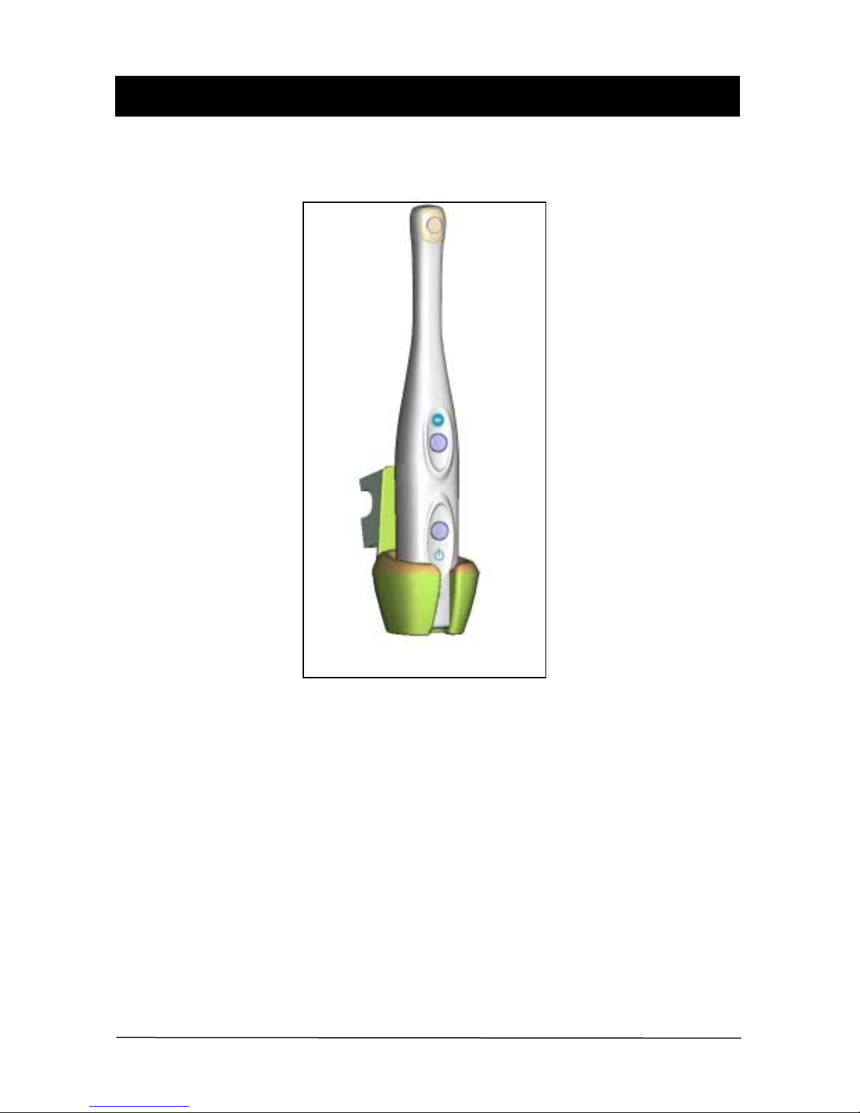
USBCam with Handpiece Holder
B1051039 Rev. B USBCam
iv

1. Introduction to USBCam
1.1. Welcome
USBCam is the newest hand-held intraoral camera from Schick Technologies. Its
lightweight design and smooth contours make it both comfortable to hold and easy to use.
Taking images with USBCam’s integrated capture button makes video capture a simple
one-step operation. And its built-in LED light source provides reliable, long-life
illumination.
Adding USBCam to your office provides the following advantages:
• Fast and easy hardware setup
• Plugs directly into your computer -- no separate power supply required
• Ports quickly from operatory to operatory -- just disconnect and reconnect
• Uses Microsoft Windows
grabbing" video card or additional device driver required
1.2. USBCam System
®
DirectX ® drivers -- no special "frame-
The USBCam system hardware consists of the following components.
• USBCam Handpiece and Holder
• USBCam Cable
• Camera Sheaths
1.3. Getting the Best Images with Your USBCam
Getting the best results from your USBCam begins with having a computer system suitable
for displaying and capturing video images. For optimum performance we recommend: (a)
PCs equipped with Pentium III processors or higher, (b) minimum 8MB video memory,
and (c) display values for your monitor set at least to 800 x 600 x 24-bit color. We also
recommend using the factory defaults for the USBCam.1
IMPORTANT! USB bandwidth is shared among all USB devices. Achieving optimum
performance with the USBCam (25 frames-per-second video streams) may not be
possible if other USB devices are in use at the same time.
1
The amount of video memory on your system can be checked by running dxdiag.exe and checking the
Display tab. Color resolution can be checked by clicking Windows Start > Settings > Control Panel,
double-clicking on Display, and then clicking on the Settings tab. Factory settings for the USBCam are:
25 frames per second frame rate, auto white balance, and auto exposure. More information about video
settings can be found in Sections B-1 and B-2.
USBCam B1051039 Rev. B
1
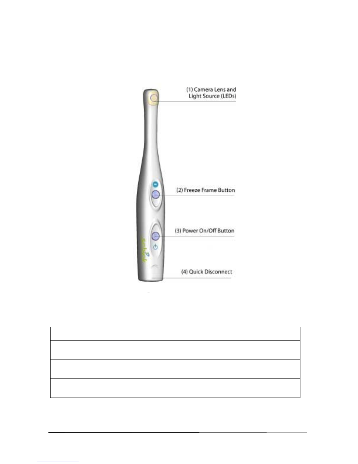
1.4. Controls on the USBCam
An illustration of the USBCam is shown below in Figure 1. For a description of user
controls on the camera, refer to Table 1.
Number Description
"
#
$
%
NOTE 1: Light source will automatically time out after 4-5 minutes of continuous operation
NOTE 2: "B" connector end of USB cable connects here
Camera lens and LED (light-emitting diode) source
Freeze frame button (set to Freeze/Unfreeze or Freeze/Take option)
Power on/off button (See Note 1)
Quick disconnect for portability (See Note 2)
B1051039 Rev. B USBCam
2
Figure 1. USBCam Controls
Table 1. Description of Camera Controls
2. Hardware Setup
2.1. Connecting the USBCam and Cable
IMPORTANT! Do not connect the USBCam and cable to your computer until after you
have installed CDR Video Manager and updated the DirectX files on your system.
Procedures for installing these files are supplied in Section 3, "Software Setup."
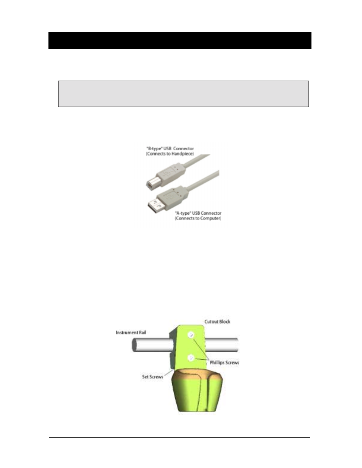
The USB cable used with the camera is a 5 meter (5.5 yards) cable, with a Series "A" USB
plug on one side and a Series "B" USB plug on the other. The "A-type" plug connects to
any available USB port on the computer. The "B-type" plug connects to the handpiece.
Figure 2. USB Cable Connectors
2.2. Installing the USBCam Handpiece Holder
The USBCam Handpiece Holder turns off the camera when the handpiece is inserted and
turns on the camera when the handpiece is removed. The holder is equipped with several
mounting options: (1) Can be mounted to a dental chair with bar attachment, (2) Can be
wall-mounted with fastening hardware, or (3) Can be attached to a wall or other acceptable
bonding surface with double-sided adhesive tape.
USBCam B1051039 Rev. B
Figure 3. Handpiece Holder Installation
3

PLEASE NOTE: When selecting the mounting option for your USBCam, choose a location
that offers easy access during patient exams and safe storage afterwards. In most
practices, mounting the USBCam to the dental chair will provide the best all-around
solution.
2.2.1. Dental Chair-Mounting Option
To install the handpiece holder to a dental chair, do the following:
1. Remove the handpiece from its holder before performing this procedure.
2. Position the holder on the instrument rail of your dental chair, using the cutout space
on the back of the holder as a guide.
3. When the holder is in position, use an Allen key to tighten 2 set screws located at the
bottom of the cutout block.
2.2.2. Wall-Mounting Option (with Fasteners)
To install the handpiece by fastening it to a wall or other vertical surface, do the following:
1. Remove the handpiece from its holder before performing this procedure.
2. Remove the cutout block from the handpiece holder by loosening 2 flat-head Phillips
screws.
3. Position the holder on a smooth stable vertical surface. Using the holes on the back of
the holder as guides, fasten the holder securely to the wall using 2 (#6 x 3/4) dry wall
screws (not supplied) or other hardware appropriate to the mounting surface.
2.2.3. Wall-Mounting Option (with Adhesive)
To install the handpiece by attaching it with adhesive tape to a wall or other vertical
surface, do the following:
1. Remove the handpiece from its holder before performing this procedure.
2. Remove the cutout block from the handpiece holder by loosening 2 flat-head Phillips
screws.
3. Cut and trim a piece of double-sided adhesive tape (not supplied) to the size of the
back of the holder. Remove one side of the tape and attach it to the holder.
4. When the holder is correctly located, remove the other side of the adhesive tape and
fasten the holder securely to the wall or other surface.
B1051039 Rev. B USBCam
4

3. Soft ware Setup
3.1. What You Will Need to Complete this Section
To expedite software installation, please have the following items available:
A. CDR Software CD (only applies to users installing the CDR program for the first time)
B. CDR Video Manager for DirectX CD
C. Windows 98 System CD (only applies to Windows 98 SE users)
D. USBCam and Cable
3.2. Before You Start Installing Software
IMPORTANT! CDR users please do not connect the USBCam and cable to your
computer until after you have installed CDR Video Manager and updated the DirectX files
on your system. Procedures for installing these files can be found in this section. Non-CDR
users please refer to the Notice Page at the beginning of this User Guide.
The software for your USBCam consists of the following components:
A. CDR Video Manager for DirectX Installation
B. DirectX Update
C. USBCam Device Driver Installation
• USB device driver
• Composite video driver
2
• Audio driver
You must install each of these components successfully to ensure proper operation of your
USBCam. Actual installation differs slightly between operating systems (Windows 98
Second Edition, Windows 2000, and Windows XP), so you should follow the procedures
that refer to your particular system. (Procedures can be found in this section.) If you're not
sure which operating system is installed on your computer, right click on the My
Computer icon on your desktop and select Properties.
2
Although an audio driver is installed during the setup process, there are no audio components associated
with the USBCam.
USBCam B1051039 Rev. B
5

3.3. Installing CDR Softw are
PLEASE NOTE: If you have already installed CDR software on your system, skip ahead
to the CDR Video Manager, DirectX update, and device driver installation procedures that
apply to your operating system.
CDR software is an essential component of every CDR system. When you receive your
CDR software, follow the short directions below to load the CDR program.
Turn on your computer (if it’s not on already), wait for the Windows desktop, and insert
the CD. The CD should install the CDR setup program automatically. If it doesn’t, click
the Start button and then on Run. When the Run dialog box opens, type
d:\cdrsetup\setup (if “d” is the drive letter for your CD-ROM drive. If your CD-ROM
drive uses a different letter, type in that one instead). Then read and follow the instructions
on each screen. When you’re all done, remove the CD and restart your computer.
Continue with the steps provided in the following paragraphs to install the CDR Video
Manager for DirectX, update your DirectX files, and install the USBCam device drivers
for your particular operating system.
B1051039 Rev. B USBCam
6
 Loading...