

Schick CDRPan PC-1000 Installation Instructions Manual

®
CDRPan
FOR PANORAMIC SYSTEMS
Installation
Instructions for Panoramic
Corporation PC-1000
Schick Technologies, Inc.
31-00 47
Long Island City, New York
11101
(718) 937-5765
(718) 937-5962 (FAX)
Part Number B1051101 Rev. –
th
Avenue

Copyright 2000 by Schick Technologies, Inc.
p
All Rights Reserved
Many of the designations used by manufacturers and sellers to
distinguish their products are claimed as trademarks. Where those
designations appear in this document, and Schick Technologies, Inc.
was aware of a trademark claim, the designations have been printed in
s or initial caps.
ca
Part Number
B1051101 Rev. –
October 3, 2000
!
Printed in the United States of America
This document was originally prepared in English

Contents
1. Introduction.................................................................................................1
1.1 Welcome ..........................................................................................................................1
1.2 CDRPan System...............................................................................................................1
1.3 Overview for Installing CDRPan.....................................................................................1
1.4 Before You Start Installing CDRPan...............................................................................2
2. What You Will Need For Installat ion.......................................................3
2.1 CDRPan System...............................................................................................................3
2.2 Tools and Materials..........................................................................................................6
3. Sensor and Co destrip...............................................................................7
3.1 Install Sensor Assembly and Sensor Clip ........................................................................7
3.2 Route Sensor Cable..........................................................................................................9
3.3 Check Sensor Cable Run................................................................................................10
3.4 Prepare to Install Codestrip............................................................................................11
3.5 Install Codestrip.............................................................................................................12
3.6 Clearance Adjustments ..................................................................................................13
4. Remote Module, Power Supply, and PCI Board.................................14
4.1 Install Remote Module...................................................................................................14
4.1.1 Tools and Materials .............................................................................................14
4.1.2 Step-by-Step Instructions......................................................................................14
4.2 Install Power Supply......................................................................................................15
4.2.1 Tools and Materials .............................................................................................15
4.2.2 Step-by-Step Instructions......................................................................................15
4.3 Install PCI Board............................................................................................................16
4.3.1 Tools and Materials .............................................................................................16
4.3.2 Step-by-Step Instructions......................................................................................16
PC-1000 Installation B1051101 Rev. –
i

Safety Issues
Electrical Concerns
CDRPan conforms to national (U.S.) and international standards for electromagnetic
compatibility and electrical safety. A complete list of specifications can be found in the
CDRPan User’s Guide.
Mechanical Considerations
The sensor package, the remote module, and the cables of the CDRPan system are
mounted outside of the patient area to ensure patient safety and reliable equipment
operation.
Radiation Concerns
No adjustments or alterations are made to the X-ray source of the panoramic equipment.
ii
B1051101 Rev. – PC-1000 Installation

1. Introduction
1.1 Welcome
The CDR Panoramic X-ray System (“CDRPan”) is an electronic imaging system that
integrates with panoramic machines to acquire, display, store and print digital X-rays.
Because of its digital format, the X-ray can be enhanced for more detail using CDR tools,
and it can be archived for patient histories and retrieved for comparisons.
1.2 CDRPan System
The CDRPan system hardware consists of the following components (unless otherwise
indicated, all part numbers (P/Ns) refer to Schick Technologies numbers):
• CDRPan kit for Panoramic Corp. PC-1000 (P/N B4770050), which includes
the sensor, codestrip, other attaching parts, and accessories
• Remote module (P/N B4750100)
• Power supply (P/N A3302300)
• PCI board (P/N B3301100) and cable (B2211001).
The CDRPan system requires the following software:
• CDR software (version 2.1 or higher)
• CDRPan software, which includes the PCI board device driver and the series
set to be used with panoramic exams
1.3 Overview for Installing CDRPan
This Installation Manual is one of two documents you will need to install the CDRPan
system completely. After performing the installation procedure in this document, you
should refer to the CDRPan User’s Guide (P/N B1051008) to install the software for the
CDRPan system. Procedures for installing CDRPan system hardware and software can be
found in the following documents.
PROCEDURE DOCUMENT
Install Sensor and Codestrip (This Manual)
Install Remote Module and Power Supply (This Manual)
Install PCI Board (This Manual)
Install PCI Device Driver CDRPan User Guide
Install CDR and CDRPan Software CDRPan User Guide
PC-1000 Installation B1051101 Rev. – 1
1.4 Before You Start Installing CDRPan
Prior to installing CDRPan on your panoramic system, please perform the following
checks.
Make sure your panoramic system is operating properly.
Familiarize yourself with the installation steps before performing them.
Determine the location of your computer. This will be useful when you install the
Remote Module and need to run cables between it and your computer.
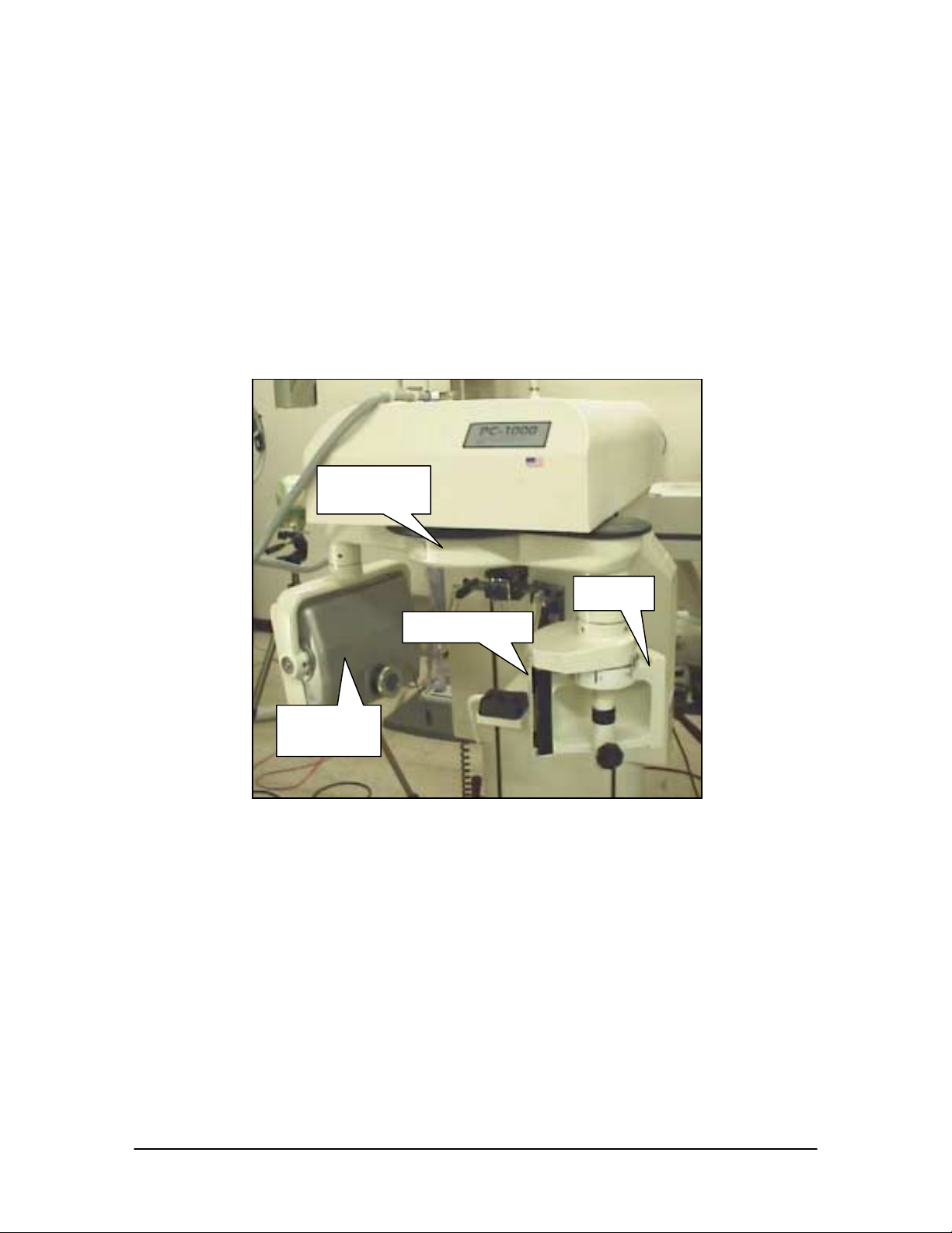
ROTATION
ARM
DRUM
FACEPLATE
X-RAY
SOURCE
Figure 1. Picture of the Panoramic Corp. PC-1000
2
B1051101 Rev. – PC-1000 Installation
2. What You Will Need For Installation
2.1 CDRPan System
To perform the installation procedures in this manual, you will need the following
CDRPan parts and assemblies.
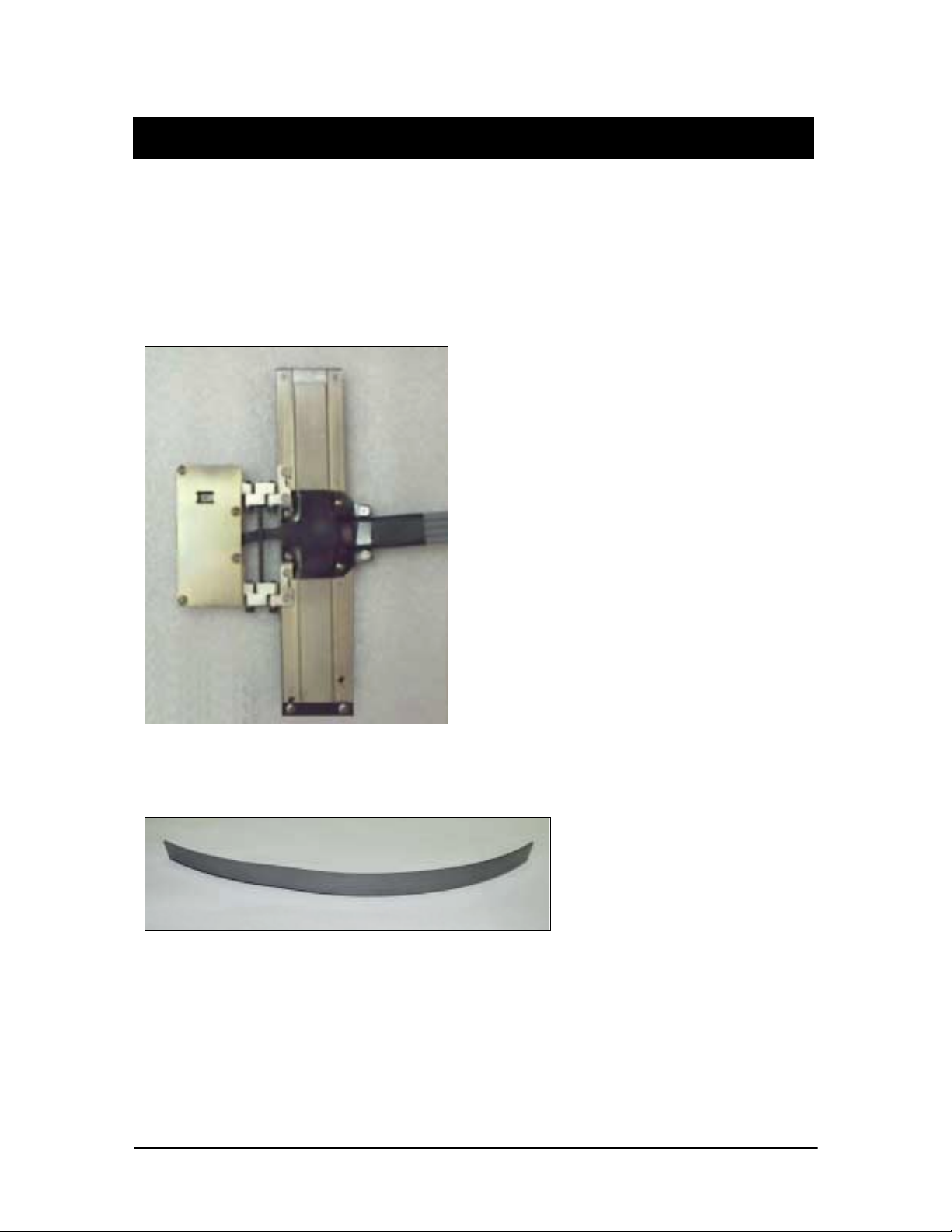
A. Sensor Assembly
B. Drum Codestrip
PC-1000 Installation B1051101 Rev. –
3
 Loading...