

schegoLUX-aqua/aquacolor
Operating Instructions
GB|
schegoLUX-aqua/aquacolor
Outflow nozzle with LED-light

Operating Instructions ...................................................................................10 - 15
D
GB
2
3
4
5
2
1
8
Abb. 1
AB
Abb. 2
Abb. 4
3
6 7
1
Abb. 3
1
Abb. 5

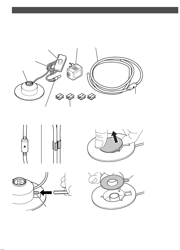
Overview / scope of delivery:
Overview / scope of delivery:
(Fig.1)
1 Outflow nozzle with LED-light
2 Power cable
3Switch
4 Transformer
5Air hose
6Plug
7Cable clips
8Check valve
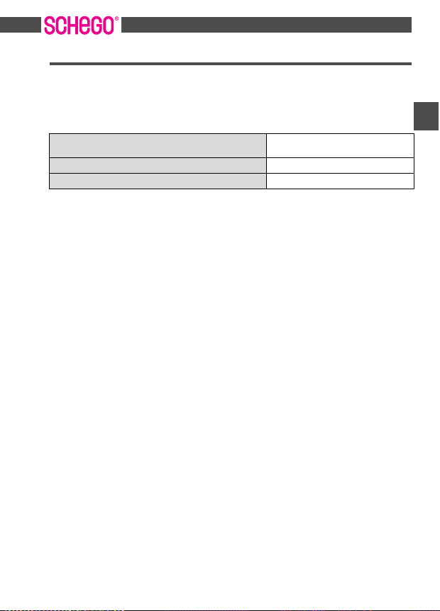
Technical data
Illuminant LED lamp
Rated voltage for illuminant 12 V/50 Hz
Power input for illuminant 2 W
Cable PVC
Cable length 2,5 m
Air hose (PVC) 3 m
Submergence depth in water 1 m
Power supply unit 230 V/50 Hz
Consum ables
Outflow stone
Check valve
10

Thank you very much!
Thank you very much!
We are very happy that you have made a decision in favour of schegoLUXaqua/aquacolor!
SchegoLUX-aqua/aquacolor is an outflow nozzle with LED lamp for use in aquariums.
Apart from that, the schego-LUX-aquacolor has an LED lamp with colour change. The LED
spotlight features minimum power consumption and a long lifetime.
Symbols in these operating instructions
Important notes for your own safety and for the avoidance of damage to the schegoLUXaqua/aquacolor are specially highlighted. Strictly follow these notes:
WAR NIN G:
Warns of dangers for your health and describes possible risks of injury.
ATTENTION:
Points to possible dangers for the outflow nozzle or other objects.
NOTE:
Emphasizes hints and information for you.
Operating Instructions
Read these operating instructions completely before starting to use the outflow nozzle.
Keep this manual in a safe place. When passing this outflow nozzle on to a third party you
must also hand over these operating instructions. Failure to comply with these
instructions may cause danger for persons and damage to objects. We do not assume
liability for personal injury or material damage resulting from disregarding these
operating instructions.
Safety notes
WAR NIN G:
The power supply unit is supplied with an electric voltage of 230V. Make sure that the
power supply unit is free of damage before using it. Use it only in a dry environment.
Do not leave the power supply unit unattended, if children or other persons, who are
unable to assess the risks, are in the vicinity.
Preparation
Unpack the complete scope of delivery and check the contents for completeness and
integrity. Overview / scope of delivery >Page 10
11
GB

Starting operation of the outflow nozzle
Always transport/send the outflow nozzle in its original packaging, to avoid damage.
Keep the packaging material for this purpose.
Dispose of packaging material, that is no longer needed, in compliance with applicable
regulations. If you discovered transport damage you should immediately contact the
dealer from whom you had purchased the outflow nozzle.
Starting operation of the outflow nozzle
WAR NIN G:
Electric voltage is highly dangerous. Make sure that the power supply unit is free of
damage before using it. The power supply unit must never come into contact with
fluids.
ATTENTION:
Incorrect voltage can damage the outflow nozzle. You should only connect the outflow
nozzle to a power supply unit with maximum 12V output.
1. Plug the air hose onto the hose socket of the outflow nozzle (Fig. 4/1).
Make sure that the arrow on the check valve in the air hose points in flow direction
(towards the outflow nozzle) (Fig. 2/A).
2. Connect the air hose to a membrane air pump.
NOTE:
Further information on membrane air pumps can be found under the following
address: http://www.schego.de.
3. Connect the air hose to the power cable. Use the supplied cable clips (Fig. 2/B) for
this purpose.
4. Place the outflow nozzle on the bottom of the aquarium.
5. Connect the plug connector (Fig. 1/6) with the power supply unit (not part of the
delivery).
ATTENTION:
Incorrect voltage can damage the power supply unit. Only connect the power supply
unit, if the electric voltage specified on the power supply unit complies with the
voltage of your wall outlet.
6. Insert the mains plug of the power supply unit into an earthing contact socket.
12

Changing the check valve
Changing the check valve
The check valve is subject to operation related wear. It needs to be changed once every
year. Please proceed as follows:
1. Cut the air hose with a pair of scissors just above and below the check valve.
2. Connect the hose connections of the new check valve with the air hose. Make sure
that the arrow on the check valve in the air hose points in flow direction (i.e. towards
the outflow nozzle) (Fig. 2/A).
Cleaning the outflow stone
Clean the outflow stone if the outflow capacity drops. Please proceed as follows:
1. Carefully lift off the bottom cover (Fig. 3).
2. Carefully pull on the hose connection (Fig. 4/1), in order to remove the outflow stone.
If necessary move the hose connection to and fro, in order to loosen the outflow
stone.
3. Rinse the outflow stone with clear water and, if necessary, clean it with a brush.
4. Put the outflow stone back into place.
5. Reinstall the bottom cover.
6. If the outflow capacity is still insufficient, the outflow stone must be replaced.
Replacing the outflow stone
The outflow stone is subject to operation related wear. Replace the outflow stone if the
outflow capacity drops. Please proceed as follows:
1. Cut the air hose with a pair of scissors just next to the outflow stone connection (Fig.
4/1).
2. Carefully lift off the bottom cover (Fig. 3).
3. Carefully pull on the hose connection (Fig. 4/1), in order to remove the outflow stone.
If necessary move the hose connection to and fro, in order to loosen the outflow
stone.
4. Assemble the new outflow stone.
5. Plug the air hose onto the hose socket of the outflow nozzle (Fig. 4/1).
6. Reinstall the bottom cover.
GB
13

Faults
Faul ts
Before submitting claims for damage to the outflow nozzle you should first try to rectify
the fault yourself by following this table.
Malfunction Cause Remedy
LED does not light Pug connection to
No air escaping from the
outflow nozzle
transformer interrupted
Transformer defective Replace the transformer
Air supply to outflow
nozzle interrupted
Operation of membrane
pump is disturbed
Check plug connection
Check whether the air
hoses is buckled or has
come looses
Check the membrane air
pump
Disposal
Once the usage period comes to an end you must dispose of the outflow nozzle and all
accessories in compliance with valid environmental regulations. Electric waste must not
be disposed of together with domestic refuse.
Warr anty
For the equipment sold by us we grant a 24 months warranty, starting with the date of
purchase (receipt). Within the warranty period we will rectify faults on equipment or
accessories*), which are caused by material or manufacturing faults, free of charge by
means of repair or, at our discretion, replacement.
Warranty adjustments do neither constitute an extension of the warranty period, nor do
they start a new warranty! The purchasing receipt serves as proof for warranty. Without
this proof a replacement or repair free of charge is not possible.
*) Both defects on consumables or wear items, as well as cleaning, maintenance or the
replacement of wear items are not covered under warranty and can thus only be
provided against payment!
14
Spare parts
Spare parts
Accessories and spare parts can be ordered from our Service Department at any time:
Schego Schemel & Goetz GmbH & Co KG • Elektrogerätebau
Schreberstraße 14 • D- 63069 Offenbach am Main
Phone 0049 (0) 69/ 83 57 48 • Fax 0040 (0) 69/ 84 71 81
e-mail info@schego.de • http://www.schego.de
Spare part Article-No.
Check valve, set of 2 652
Outflow stone 380
GB
15

 Loading...