

Page 1
TECHNICAL DOCUMENTATION
PERFORMANCE DATA
TESTS AND STANDARDS
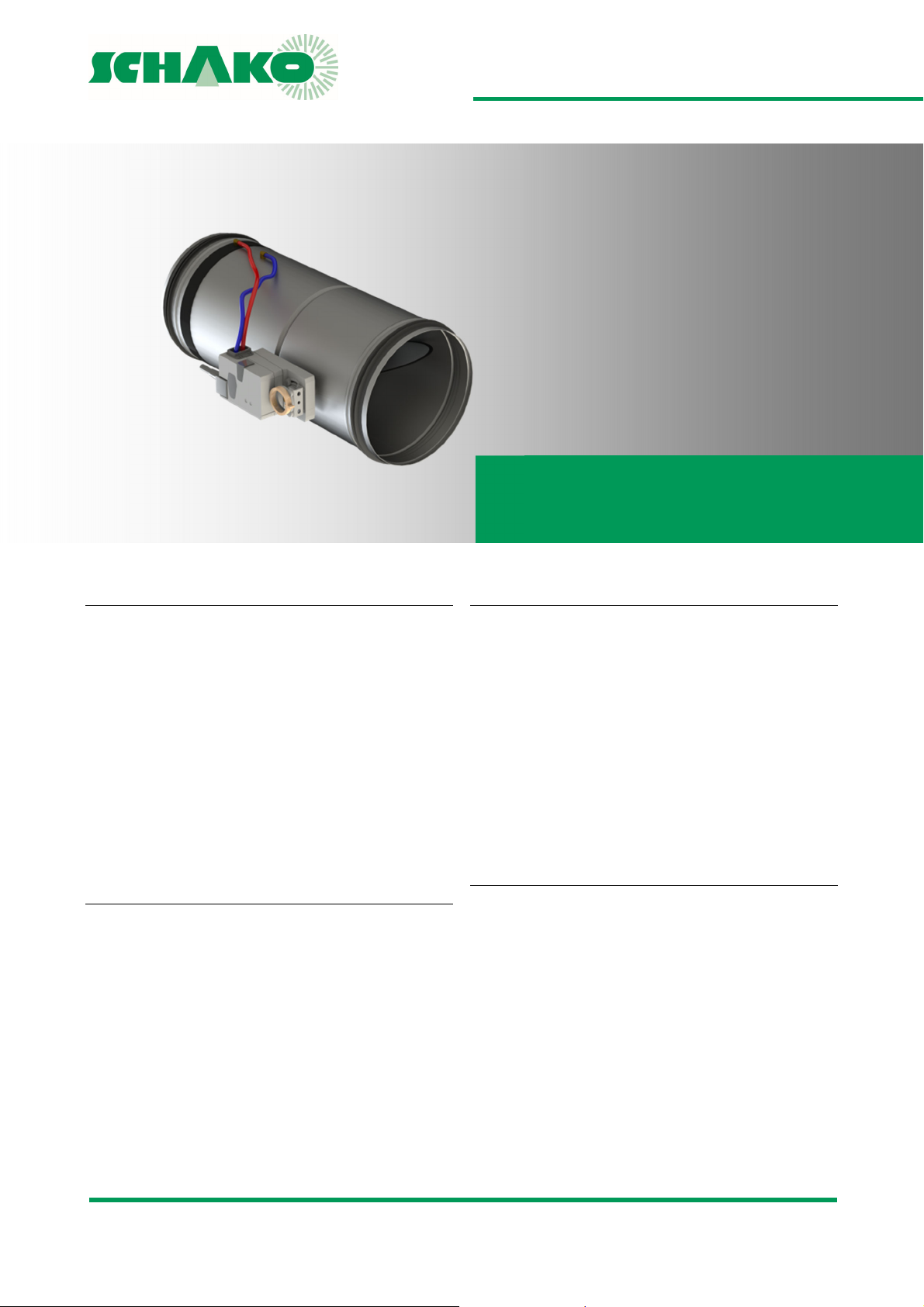
VLV55|VLV65
Volumetric flow controller
Operating temperature: 10 - 50 °C
Differential pressure range: 20 - 750 Pa
Volumetric flow measurement range from 13 m
3
2195 m
/h
Minimum pressure difference 5 to 150 Pa
VLV55
for air velocity 0.5 to 5 m/s
VLV65
for air velocity 1 to 8 m/s
3
/h to
VDI 6022, Sheet 1: Hygienic requirements of ventila-
tion and air-conditioning systems
DIN EN 13779 (2007): Ventilation of non-residential
buildings
Leakage air: EN 1751 (2014-06)
DIN EN 1751, class 4: Leakage with damper blade
closed
DIN EN 1751, class C: Housing leakage
APPROVALS AND CERTIFICATES
SPECIAL FEATURES
RoHS 2002/95/EC
after moulded parts no inflow area required
optimised for air velocities from 0.5 m/s
high control accuracy at low pressures and air veloci-
ties
position-independent installation
resistant to pollution due to the design
EMC 2004/108/EC
Low voltage 2006/95/EC
SCHAKO | Ferdinand Schad KG Telefon 0 7463-980-0
Steigstraße 25-27 Fax 0 7463-980-200
D-78600 Kolbingen www.schako.de | infoschako.de
Page 2

VLV55|VLV65 - Volumetric flow controller
TECHNICAL DOCUMENTATION
Table of Contents
TABLE OF CONTENTS
Table of Contents ................................................................................................................... 2
Overview of product versions ................................................................................................ 3
Function ................................................................................................................................. 3
Areas of application ............................................................................................................... 4
Processing .............................................................................................................................. 4
Available sizes ........................................................................................................................ 5
Useable volumetric flow ranges ............................................................................................ 5
Accessories ............................................................................................................................ 6
Dimensions of accessories ..................................................................................................... 6
Available sizes of accessories ................................................................................................. 6
Static minimum pressure difference ..................................................................................... 7
VLV55 - flow generated noise ................................................................................................ 8
VLV55 - flow generated noise - relative sound spectrum ...................................................... 9
VLV55 - radiated noise ......................................................................................................... 10
VLV55 - radiated noise - relative sound spectrum ............................................................... 11
VLV65 - flow generated noise .............................................................................................. 12
VLV65 - flow generated noise - relative sound spectrum .................................................... 13
VLV65 - Radiated noise ........................................................................................................ 14
VLV65 - Radiated noise - relative sound spectrum .............................................................. 15
Duct silencer (-RS) - insertion loss ....................................................................................... 16
Controller selection ............................................................................................................. 17
Technical data of control components ................................................................................ 17
Circuit diagrams - Belimo ..................................................................................................... 18
Circuit diagrams - Gruner..................................................................................................... 21
Setting the operating potentiometers ................................................................................. 22
Technical data of controllers and motors ............................................................................ 24
Startup using PC-Tool .......................................................................................................... 26
Startup using the setting and diagnostic device ZTH EU (Belimo) ....................................... 27
Startup using the setting device GUIV-A ............................................................................. 28
Smartphone app - Belimo Assistant .................................................................................... 28
Prior to assembly and commissioning ................................................................................. 29
Installation information ....................................................................................................... 29
Maintenance and service ..................................................................................................... 29
Legend ................................................................................................................................. 29
Order code ........................................................................................................................... 30
Specification text ................................................................................................................. 31
Construction subject to change
No return possible Version: 2017-04-24 | Page 2
Page 3
VLV55|VLV65 - Volumetric flow controller
TECHNICAL DOCUMENTATION
Overview of product versions | Function
OVERVIEW OF PRODUCT VERSIONS
FUNCTION
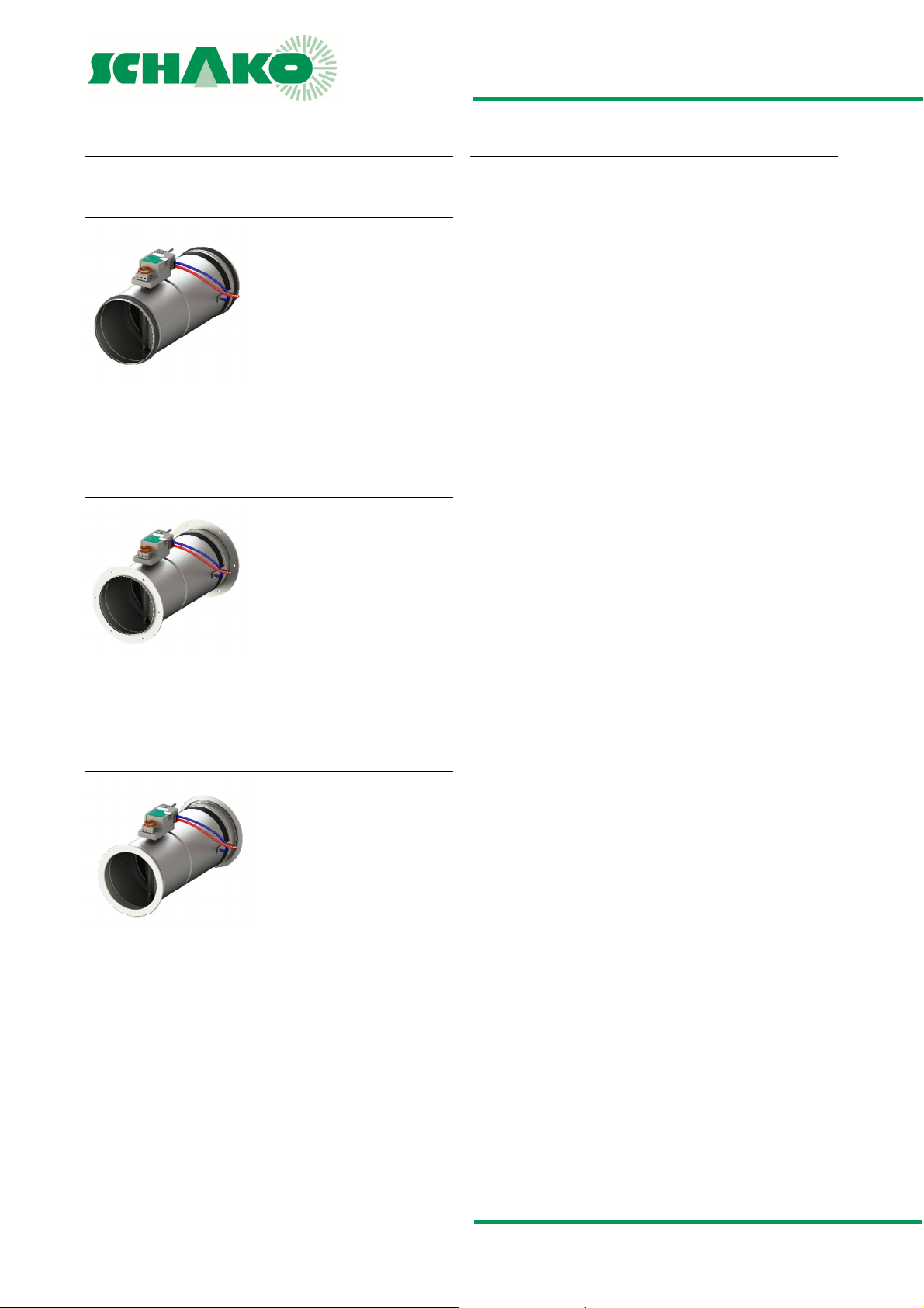
VLV55|VLV65 with rubber lip seal
Round volumetric flow controller
Volumetric flow range 0.5-5 m/s (VLV55) or 1-8 m/s (VLV65)
With rubber lip seal (-GD1)
VLV55|VLV65 with flat flange
Round volumetric flow controller
Volumetric flow range 0.5-5 m/s (VLV55) or 1-8 m/s (VLV65)
With flat flange according to DIN 24154, class 5 (-FF1)
VLV55|VLV65 with METU flange
A volumetric flow controller is used for pressure-independent
volumetric flow regulation in ventilation and air-conditioning
systems. It serves to keep the volumetric flow either constant
within specified limits (CAV) or to control it variably (VAV).
The housing, measuring nozzle and the controller with pressure
sensor form a closed control loop with feedback, allowing de-
mand-dependent, energy-saving air-conditioning of the single
rooms or areas of air-conditioning systems also at low duct
pressures and air velocities. When suitable controller types are
used, room or duct pressure regulation can be achieved.
For the measurement of the effective pressure, SCHAKO is us-
ing its measuring method by means of a standardised Venturi
nozzle made of aluminium to DIN EN ISO 5167. In front of the
Venturi nozzle and in the nozzle neck, the volumetric flow con-
troller is fitted with openings for pressure take-off. The result-
ing differential pressure (effective pressure) is measured and
evaluated by a universal or compact controller. The VLV meas-
urement principle allows measurement of small volumetric
flows. In comparison with measuring rods, measuring crosses
or measuring orifices having fewer measuring points, this gives
higher accuracy, allowing the inflow area required in front of
the volumetric flow controller to be omitted. This also allows
smaller measurement tolerances to be achieved.
The volumetric flow controllers of the VLV type are insensitive
to dirt caused by dust and can be installed and used inde-
pendently of their position. The mounting instructions docu-
mented by the manufacturer must be adhered to, as otherwise
the correct functioning of the volumetric flow controller is not
guaranteed. The volumetric flow controllers type VLV are not
suitable for air containing sticky and greasy particles (e.g.
kitchen exhaust air).
Round volumetric flow controller
Volumetric flow range 0.5-5 m/s (VLV55) or 1-8 m/s (VLV65)
With METU flange type AF, without tension ring (-MF1)
Construction subject to change
No return possible Version: 2017-04-24 | Page 3
Page 4

VLV55|VLV65 - Volumetric flow controller
TECHNICAL DOCUMENTATION
Areas of application | Processing
AREAS OF APPLICATION
PROCESSING
for supply and return air systems with low pressures
and low air velocity
for constant CAV or variable VAV installations
for positive control V
For volumetric flow and linear pressure control
at ambient temperatures 0° to +50°C,
requirement: measuring air 0...+50°C/5...95% rH,
non-condensing
for regulating the air velocity in the duct in
the range of 0.5...8 m/s
VLV55 for air velocity 0.5 - 5 m/s
VLV65 for air velocity 1 - 8 m/s
Minimum pressure difference of 5 - 150 Pa
When using volumetric flow controllers in roof central units, in
extreme cases, condensation can build up in the measuring
pipes of the volumetric flow controller as a result of the large
temperature differences between the air flowing through the
volumetric flow controller and the surrounding air. This condensation may affect or damage the sensor. This is why for this
field of application care must be taken to insulate the housings
of the volumetric flow controllers and the measuring hoses (to
prevent condensation) and to mount the controllers in such a
way that any condensate formed on the outside of the measuring hoses can run downward and be drained (without entering
the sensor).
When connecting SCHAKO components to customer installations, any compatibility problems are beyond our scope of responsibility and must be solved on site.
min
, V
, V
, "OPEN" or "CLOSED"
mid
max
Tests and standards
The volumetric flow controller VLV-… has been tested by the
designated body in accordance with the following regulations:
Completed tests
VDI 6022, Sheet 1: Hygienic requirements of ventilation and
air-conditioning systems
DIN EN 1751: Ventilation for buildings - Air terminal devices -
Aerodynamic testing of damper and valves
DIN EN 13779 (2007): Ventilation of non-residential buildings
Applied standards
Leakage classification: DIN EN 1751 (2014-06)
RoHS 2002/95/EC
EMC 2004/108/EC
Housing
Galvanised sheet steel (-SV)
Galvanised sheet steel with DD coating (-DD)
Housing leakage according to DIN EN 1751, class C
Damper blade
Galvanised sheet steel (-SV)
Galvanised sheet steel with DD coating (-DD)
Damper axle
Passivated steel
Brass
Damper blade seal
made of EPDM, silicone-free, halogen-free
airtight sealing design to DIN-EN 1751, class 4
Ring chamber sealing
made of EPDM, silicone-free, halogen-free
Damper bearing
Plastic bearing
Measuring sensor
round Venturi nozzle made of aluminium
to DIN EN ISO 5167 (-SV)
round Venturi nozzle made of aluminium
to DIN EN ISO 5167 with DD coating (-DD)
Model
round model, for round ductwork connection to DIN EN 1506,
with damper blade seal for airtight sealing to DIN EN 1751,
class 4
VLV55 for air velocity 0.5 to 5 m/s
VLV65 for air velocity 1 to 8 m/s
Controller
LMV-D3-MP-SO, 5 Nm (-A001)
LMV-D3-MF-SO, 5 Nm (-A006)
227VM-024-05, 5 Nm (-A061)
Other controllers available on request
Construction subject to change
No return possible Version: 2017-04-24 | Page 4
Page 5
VLV55|VLV65 - Volumetric flow controller
TECHNICAL DOCUMENTATION
Available sizes | Useable volumetric flow ranges
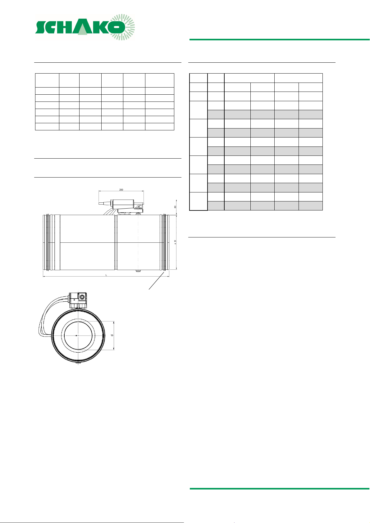
AVAILABLE SIZES
USEABLE VOLUMETRIC FLOW RANGES
NW
[mm]
øD
[mm]
d (55)
[mm]
d (65)
[mm] L [mm]
Weight
[kg]
100 98 53 63 330 1.5
125 123 67 79 370 1.9
160 158 86 102 420 2.5
200 198 108 128 480 3.4
250 248 136 160 570 4.8
315 313 171 203 690 7.0
NW 100 - NW 315 sealing airtight to DIN-EN 1751, class 4.
Dimensions
VLV55 / VLV65
Detail X
VLV55 VLV65
NW V V
min
V
V
max
V
min
max
(mm) (0.5 m/s) (5 m/s) (1 m/s) (8 m/s)
m³/h 13 132 26 211
100
l/s 4 37 7 59
m³/h 21 210 42 334
125
l/s 6 58 12 93
m³/h 35 346 69 554
160
l/s 10 96 19 154
m³/h 55 546 109 874
200
l/s 15 152 30 243
m³/h 86 859 172 1374
250
l/s 24 239 48 382
m³/h 137 1372 274 2195
315
l/s 38 381 76 610
ATTENTION: Important for parameterisation of the VLV
The table corresponds to the complete measuring range.
When the air volume drops below V
ing of the volumetric flow controller is no longer guaranteed.
If only V
is specified in the order, a variable volumetric
max
flow controller will be delivered. The V
the value specified in the catalogue.
If only one air volume is specified in the order (as V
), then the volumetric flow controller will be delivered as
stant
a constant volumetric flow controller. The volume specified
in the order is set to the V
value, and the V
min
to 100%.
The air volumes V
min
and V
and the operating mode 0/2-10
max
V can be changed directly at the controller within the nominal volumetric flow.
For the parameter setting of the control components, an air
density of 1.2 kg/m³ has been taken into account.
If no values are specified in the order, the controller will be
programmed with the values of the complete measuring
range. The following calibration curves are taken into account:
--- VLV55 ... 5 m/s;
--- VLV65 ... 8 m/s.
The first adjustment of the V
min
, V
metric flows is done prior to delivery ex works in accordance
with customer specifications (calibration for delivery address).
When these values are set, the functions of all volumetric flow
controllers are also checked.
the correct function-
min,
value will be set to
min
and V
max
nenn
min
value is set
max
operating volu-
or V
kon-
Construction subject to change
No return possible Version: 2017-04-24 | Page 5
Page 6
VLV55|VLV65 - Volumetric flow controller
TECHNICAL DOCUMENTATION
Accessories | Dimensions of accessories
ACCESSORIES
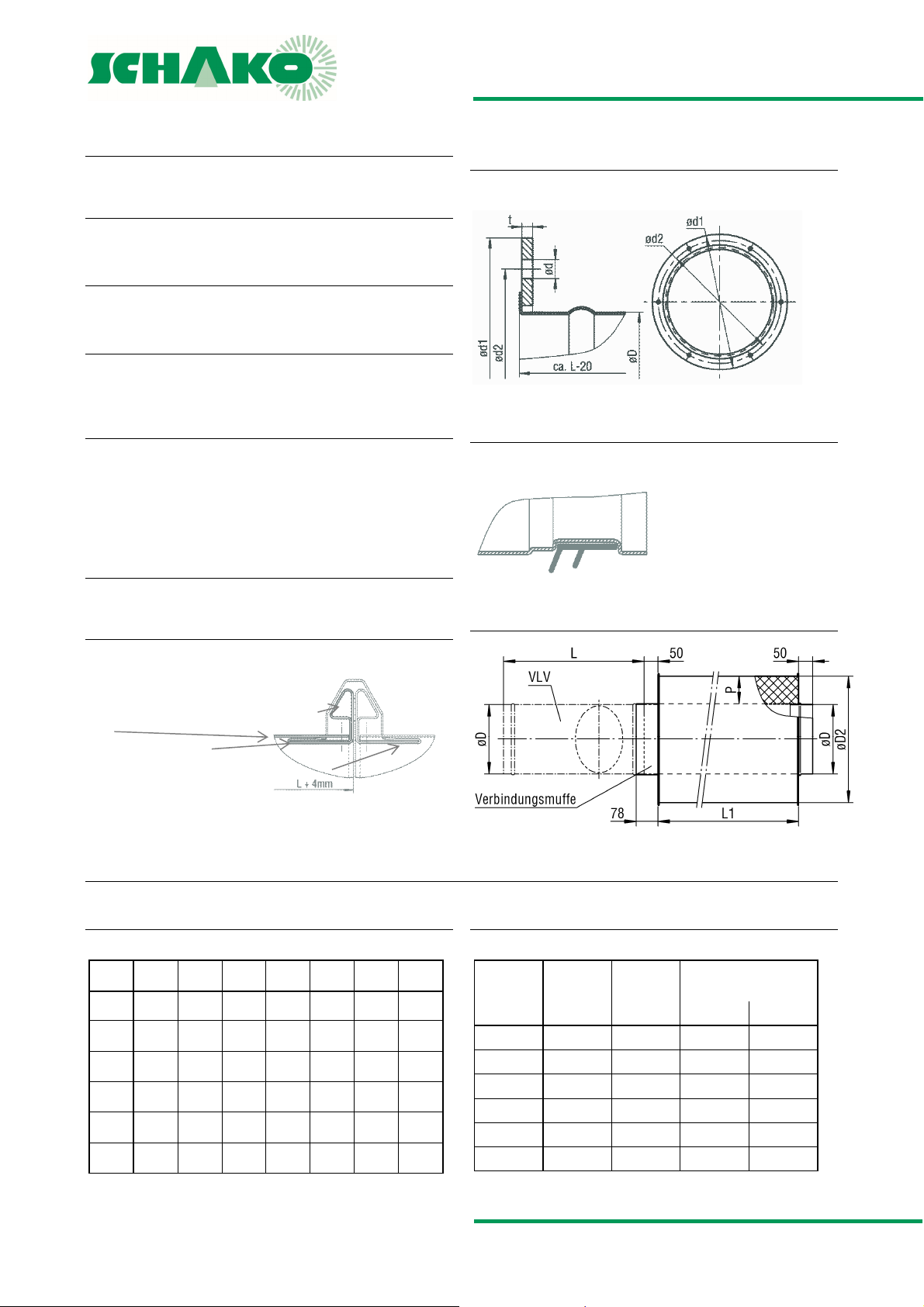
Flat flange (-FF1), on both sides
to DIN 24154/5
METU flange (-MF1)
on both sides, duct flange type AF.
Flat flange (-FF1)
on both sides, according to DIN 24154/5.
Rubber lip seal (-GD1)
on both sides, special rubber.
Duct silencer (-RS)
Rubber lip seal (-GD1)
Rigid model
Outer jacket and perforated sheet made of galvanised sheet
steel
mineral wool filling
DIMENSIONS OF ACCESSORIES
METU flange (-MF1)
Tension ring (provided by the customer)
VLV
Metu flange (-MF1)
Counter flange (provided by the customer)
AVAILABLE SIZES OF ACCESSORIES
-FF - Flat flange
Detail X
Duct silencer (-RS)
-RS - Duct silencer
NW øD ød1 ød2 ød L LOA t
100 98 154 129 7 340 4 3
125 123 177 155 7 360 4 3
160 158 222 194 7 410 6 4
200 198 263 235 7 450 6 4
250 248 313 286 7 500 6 4
315 313 388 356 9.5 600 8 5
NW L øD øD2
50 100
100 340 98 200 300
125 360 123 225 325
160 410 158 260 360
200 450 198 300 400
250 500 248 350 450
315 600 313 415 515
Construction subject to change
No return possible Version: 2017-04-24 | Page 6
P (mm)
Page 7
VLV55|VLV65 - Volumetric flow controller
TECHNICAL DOCUMENTATION
Static minimum pressure difference |
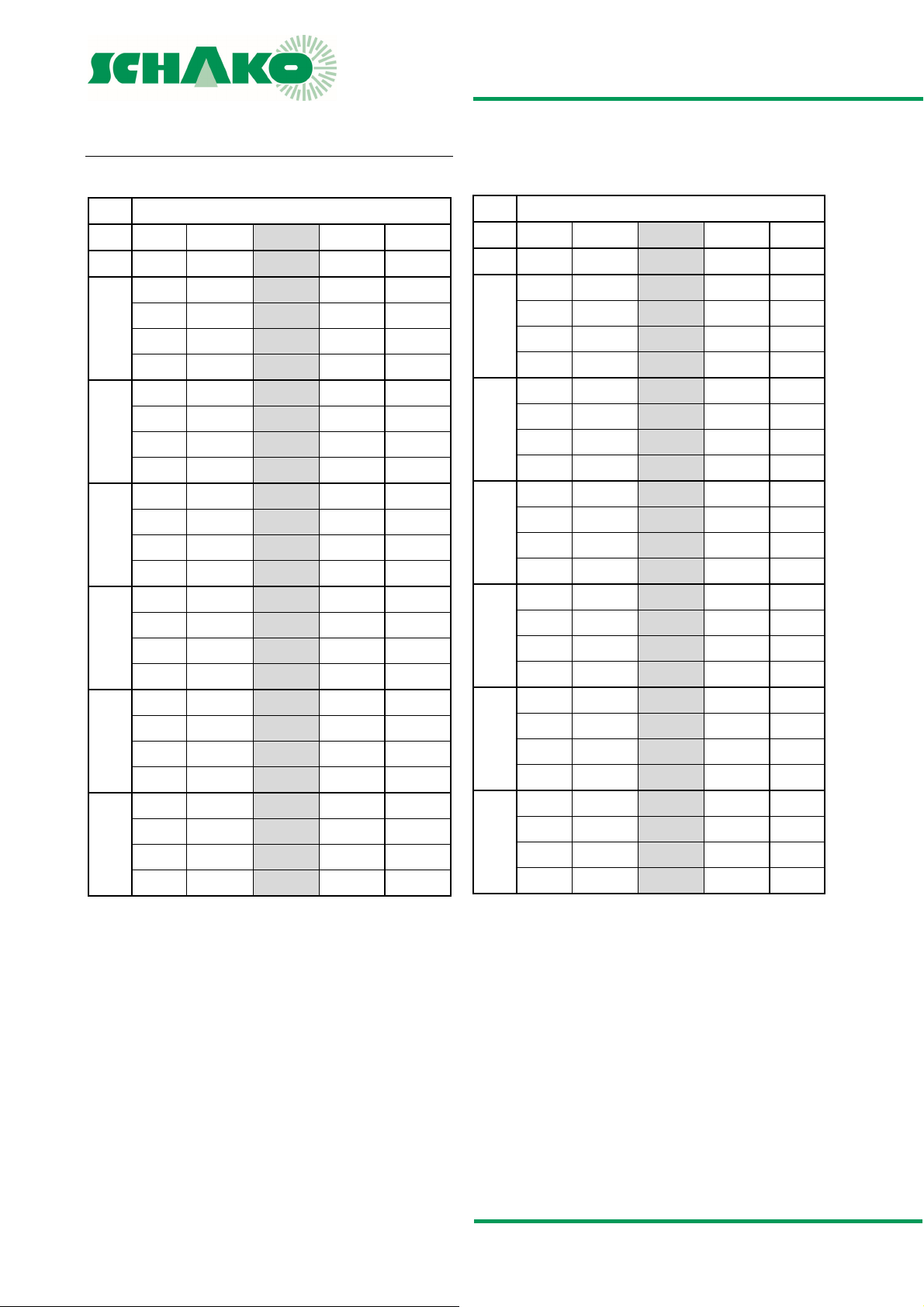
STATIC MINIMUM PRESSURE DIFFERENCE
VLV55
NW vk V V ∆p
(m/s) (m3/h) [l/s] (Pa) ±%
0.5 13
2 53 15 15 10
100
4 105 29 75 7
5 132 37 100 5
0.5 21
2 84 23 20 10
125
4 167 46 75 7
5 209 57 110 5
0.5 35
2 139 38 15 10
160
4 277 77 60 7
5 346 96 100 5
0.5 55
2 218 61 20 10
200
4 436 121 60 7
5 546 152 100 5
0.5 86
2 344 96 20 10
250
4 687 191 60 7
5 859 239 90 5
0.5 137
2 549 153 20 10
315
4 1097 305 65 7
5 1372 381 90 5
4 5 15
6 5 15
10 5 15
15 5 15
24 5 15
38 5 15
V
t min
VLV65
NW vk V V ∆p
(m/s) (m3/h) [l/s] (Pa) ±%
1 26
3 79 22 25 10
100
6 158 44 90 7
8 210 58 150 5
1 42
3 125 35 25 10
125
6 250 70 90 7
8 334 93 140 5
1 69
3 208 58 20 10
160
6 416 116 50 7
8 554 154 90 5
1 109
3 328 91 20 10
200
6 655 182 65 7
8 874 243 100 5
1 172
3 515 143 15 10
250
6 1031 286 55 7
8 1374 382 85 5
1 274
3 823 229 20 10
315
6 1646 457 55 7
8 2195 610 90 5
7 5 15
12 5 15
19 5 15
30 5 15
48 5 15
76 5 15
V
t min
Construction subject to change
No return possible Version: 2017-04-24 | Page 7
Page 8
VLV55|VLV65 - Volumetric flow controller
TECHNICAL DOCUMENTATION
VLV55 - flow generated noise |
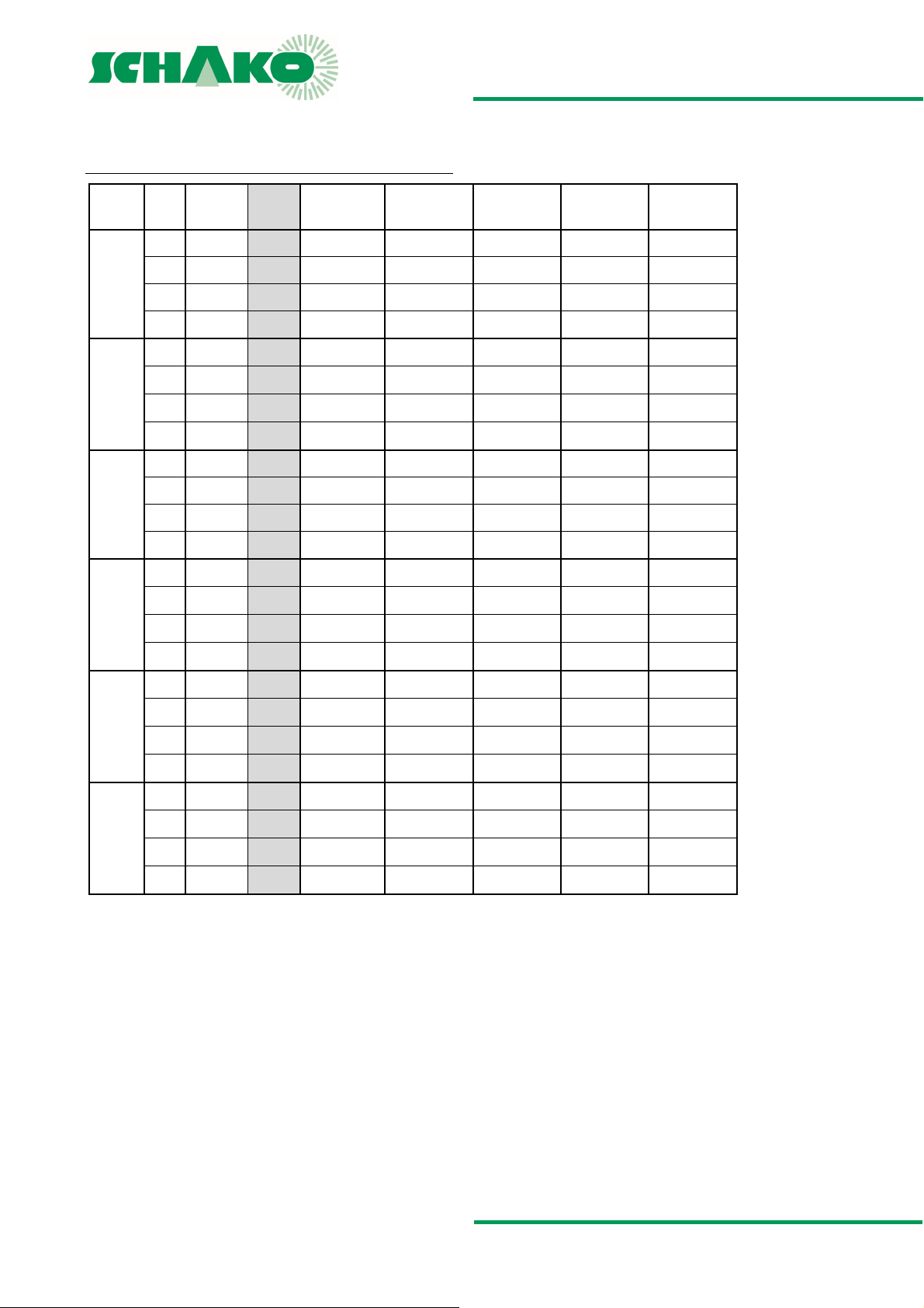
VLV55 - FLOW GENERATED NOISE
VLV55
NW
100
125
160
200
250
315
--- = value below the static minimum pressure difference
VK
(m/s) V (m3/h) V [l/s]
0.5 13 4
2 53 15
4 105 29
5 132 37
0.5 21
2 84 23
4 167 46
5 209 57
0.5 35
2 139 38
4 277 77
5 346 96
0.5 55 15
2 218 61
4 436 121
5 546 152
0.5 86 24
2 344 96
4 687 191
5 859 239
0.5 137
2 549 153
4 1097 305
5 1372 381
6
10
38
∆pt = 50 Pa
LWA [dB(A)]
29 33
44 50
44 54
--- 56
35 38
49 54
47 58
--- 56
38 45
51 57
50 60
--- 58
41 45
49 59
49 59
--- 59
42 50
50 59
51 60
--- 63
44 48
52 60
53 61
--- 63
∆pt = 100 Pa
LWA [dB(A)]
∆pt = 150 Pa
LWA [dB(A)]
36 41 43
54 56 58
59 62 64
61 65 67
43 45 48
58 59 61
63 65 67
63 67 69
46 50 51
60 62 63
64 67 68
65 68 71
47 49 51
59 66 68
64 67 70
65 68 71
56 60 62
63 66 69
64 67 70
65 68 71
52 54 57
64 66 69
65 69 71
67 70 72
∆pt = 200 Pa
LWA [dB(A)]
∆pt = 250 Pa
LWA [dB(A)]
Construction subject to change
No return possible Version: 2017-04-24 | Page 8
Page 9
VLV55|VLV65 - Volumetric flow controller
TECHNICAL DOCUMENTATION
VLV55 - flow generated noise - relative sound spectrum |
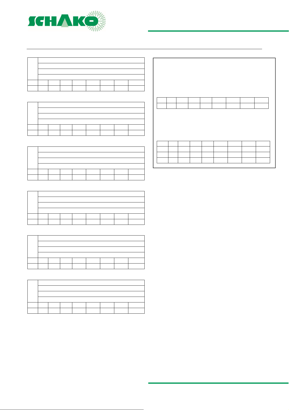
VLV55 - FLOW GENERATED NOISE - RELATIVE SOUND SPECTRUM
NW100
Relative sound spectrum (dB)
Correction value KL
Frequency (Hz)
Hz 63 125 250 500 1000 2000 4000 8000
KL -6 -8 -6 -1 -4 -13 -18 -25
NW125
Relative sound spectrum (dB)
Correction value KL
Frequency (Hz)
Hz 63 125 250 500 1000 2000 4000 8000
KL -8 -9 -5 -1 -3 -12 -19 -26
Size 160
Relative sound spectrum (dB)
Correction value KL
Frequency (Hz)
Hz 63 125 250 500 1000 2000 4000 8000
KL -6 -7 -3 -1 -4 -9 -17 -27
NW200
Relative sound spectrum (dB)
Correction value KL
Frequency (Hz)
Hz 63 125 250 500 1000 2000 4000 8000
KL -6 -5 -1 0 -7 -11 -18 -26
NW250
Relative sound spectrum (dB)
Correction value KL
Frequency (Hz)
Hz 63 125 250 500 1000 2000 4000 8000
KL -1 -2 1 -1 -7 -10 -18 -28
Size 315
Relative sound spectrum (dB)
Correction value KL
Frequency (Hz)
Hz 63 125 250 500 1000 2000 4000 8000
KL -3 -1 3 -1 -6 -10 -18 -28
Differential pressure range: 0 - 300 Pa
Air velocity: 0.5 - 5.0 m/s
KL= correction value; relative sound power level, relative to LWA
KLW = LWA + {KL}
C A L C U L A T I O N E X A M P L E
VLV55 design data
NW 160 mm | V=247 m³/h |
p=100 Pa | L
Hz 63 125 250 500 1000 2000 4000 8000
KL -6 -7 -3 -1 -4 -9 -17 -27
Calculate sound values according to formula
K
LW(relativ)
gives
Hz 63 125 250 500 1000 2000 4000 8000
LWA 60 60 60 60 60 60 60 60
KL -6 -7 -3 -1 -4 -9 -17 -27
KLW 54 53 57 59 56 51 43 33
= 60 dB(A)
WA
= LWA + {KL}
Construction subject to change
No return possible Version: 2017-04-24 | Page 9
Page 10
VLV55|VLV65 - Volumetric flow controller
TECHNICAL DOCUMENTATION
VLV55 - radiated noise |
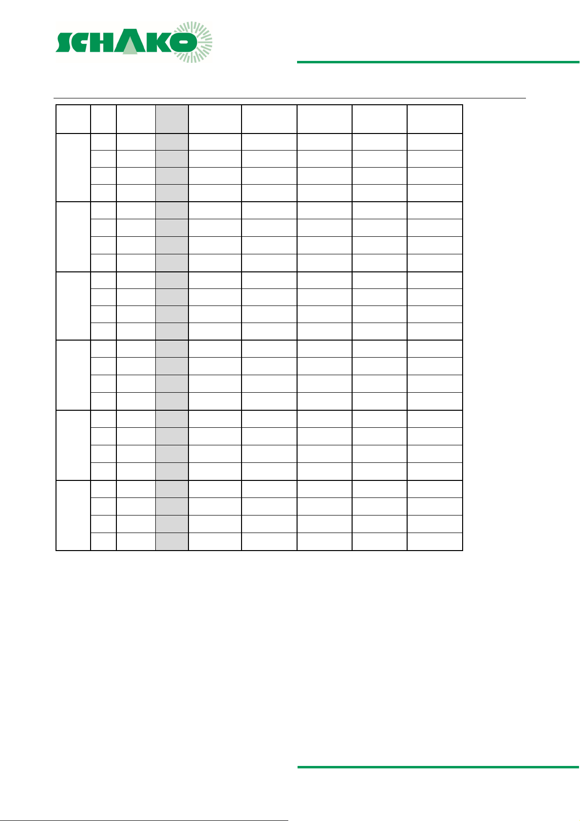
VLV55 - RADIATED NOISE
VLV55
NW
100
125
160
200
250
315
--- = values below 25 dB(A)
VK
(m/s)
0.5 13 4
2 53 15
4 105 29
5 132 37
0.5 21
2 84 23
4 167 46
5 209 57
0.5 35 10
2 139 38
4 277 77
5 346 96
0.5 55 15
2 218 61
4 436 121
5 546 152
0.5 86 24
2 344 96
4 687 191
5 859 239
0.5 137 38
2 549 153
4 1097 305
5 1372 381
V
(m3/h) V [l/s]
6
∆pt = 50 Pa
LWA [dB(A)]
--- ---
--- ---
--- 27
--- 32
--- ---
--- 25
25 28
--- 33
--- ---
--- 28
--- 34
--- 38
--- ---
--- 33
--- 41
--- 43
--- ---
--- 34
--- 40
--- 41
--- 33
--- 45
--- 45
--- 44
∆pt = 100 Pa
LWA [dB(A)]
∆pt = 150 Pa
LWA [dB(A)]
--- --- ---
25 28 30
30 33 34
34 36 38
--- --- ---
--- 29 30
32 33 36
35 38 42
--- --- 25
31 33 36
37 39 40
40 42 44
--- 25 26
36 39 41
45 47 49
46 49 52
--- 27 31
36 39 41
43 45 47
43 46 48
35 38 40
46 48 50
47 48 50
46 50 52
∆pt = 200 Pa
LWA [dB(A)]
∆pt = 250 Pa
LWA [dB(A)]
Construction subject to change
No return possible Version: 2017-04-24 | Page 10
Page 11
VLV55|VLV65 - Volumetric flow controller
TECHNICAL DOCUMENTATION
VLV55 - radiated noise - relative sound spectrum |
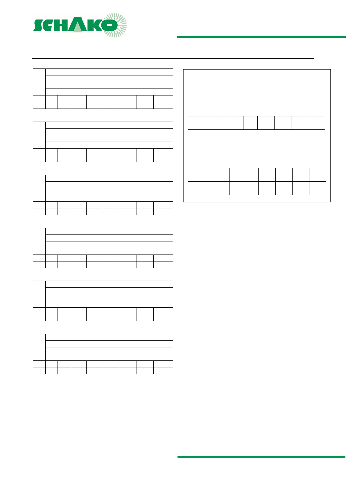
VLV55 - RADIATED NOISE - RELATIVE SOUND SPECTRUM
NW100
Relative sound spectrum (dB)
Correction value KL
Frequency (Hz)
Hz 63 125 250 500 1000 2000 4000 8000
KL 1 -1 -9 -8 -7 -5 -9 -11
NW125
Relative sound spectrum (dB)
Correction value KL
Frequency (Hz)
Hz 63 125 250 500 1000 2000 4000 8000
KL 4 2.4 -7 -3 -7 -7 -9 -14
Size 160
Relative sound spectrum (dB)
Correction value KL
Frequency (Hz)
Hz 63 125 250 500 1000 2000 4000 8000
KL 3 2 -3 -5 -6 -8 -9 -10
NW200
Relative sound spectrum (dB)
Correction value KL
Frequency (Hz)
Hz 63 125 250 500 1000 2000 4000 8000
KL -3 -4 -8 -6 -7 -6 -7 -9
NW250
Relative sound spectrum (dB)
Correction value KL
Frequency (Hz)
Hz 63 125 250 500 1000 2000 4000 8000
KL 2 0 -2 -5 -8 -6 -8 -11
Size 315
Relative sound spectrum (dB)
Correction value KL
Frequency (Hz)
Hz 63 125 250 500 1000 2000 4000 8000
KL -3 -4 -2 -4 -8 -7 -7 -18
Differential pressure range: 0 - 300 Pa
Air velocity: 0.5 - 5.0 m/s
KL= correction value; relative sound power level, relative to LWA
KLW = LWA + {KL}
C A L C U L A T I O N E X A M P L E
VLV55 design data
NW 160 mm | V=247 m³/h |
p=100 Pa | L
Hz 63 125 250 500 1000 2000 4000 8000
KL 3 2 -3 -5 -6 -8 -9 -10
Sound values calculated according to formula
K
LW(relativ)
gives
Hz 63 125 250 500 1000 2000 4000 8000
LWA 34 34 34 34 34 34 34 34
KL 3 2 -3 -5 -6 -8 -9 -10
KLW 37 36 31 29 28 26 25 24
= 34 dB(A)
WA
= LWA + {KL}
Construction subject to change
No return possible Version: 2017-04-24 | Page 11
Page 12
VLV55|VLV65 - Volumetric flow controller
TECHNICAL DOCUMENTATION
VLV65 - flow generated noise |
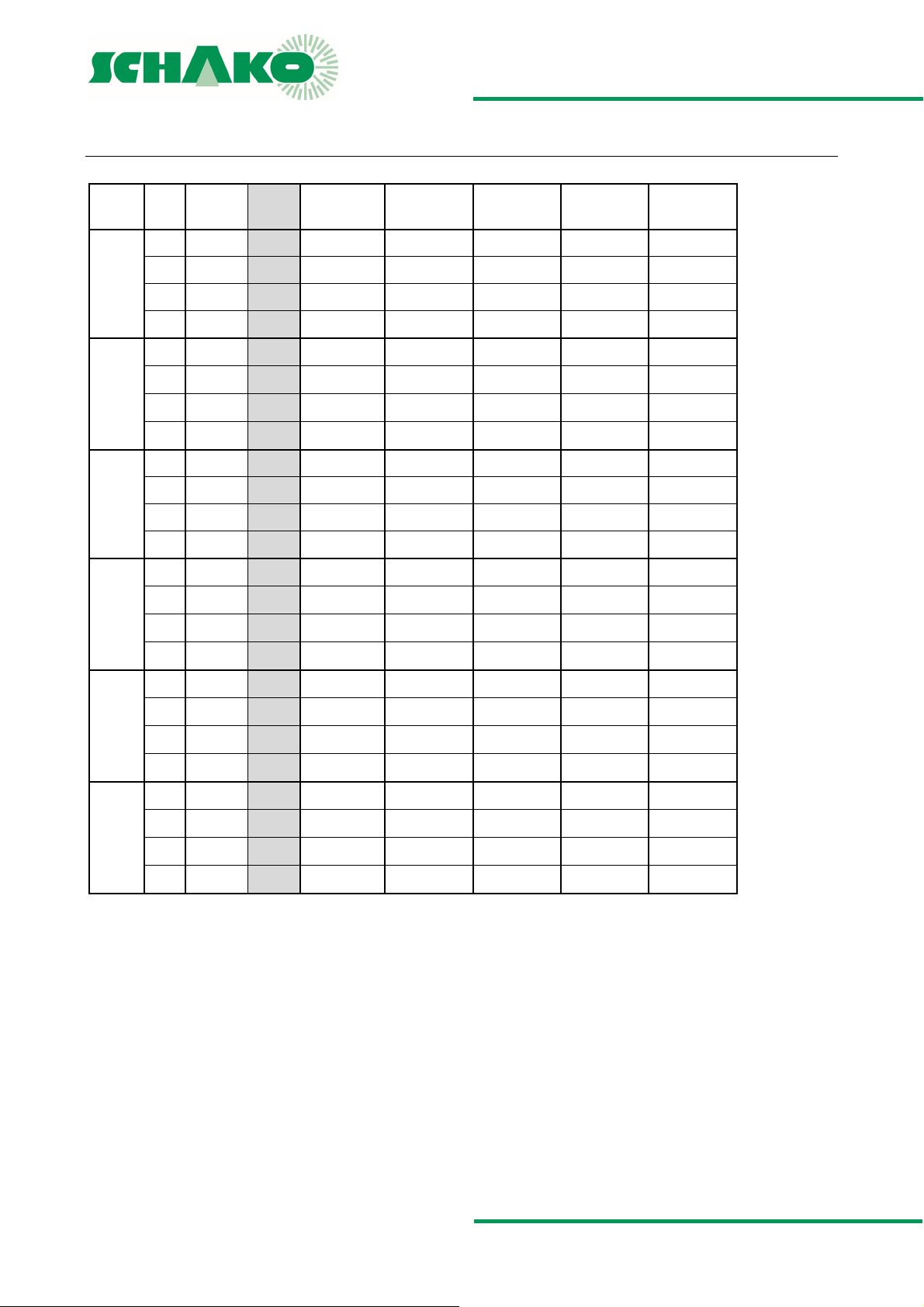
VLV65 - FLOW GENERATED NOISE
VLV65
NW
VK
(m/s)
V
(m3/h) V [l/s]
1 26 7
3 79 22
∆pt = 50 Pa
[dB(A)]
L
WA
38 43
48 53
∆p
L
100
5 130 35
8 210 58
1 42
12
3 125 35
48 57
--- ---
41 45
50 58
125
5 210 60
8 334 93
1 69
19
3 208 58
47 59
--- ---
45 49
50 58
160
5 345 95
8 554 154
1 109 30
3 328 91
51 59
--- 61
46 52
49 59
200
5 545 150
8 874 243
1 172 48
3 515 143
51 60
--- 60
49 54
49 59
250
5 860 240
8 1374 382
1 274
76
3 823 229
52 60
--- 62
50 55
52 60
315
5 1370 380
8 2195 610
54 62
64 67
--- = value below the static minimum pressure difference
= 100 Pa
t
[dB(A)]
WA
∆p
= 150 Pa
t
L
WA
[dB(A)]
∆p
= 200 Pa
t
[dB(A)]
L
WA
∆p
= 250 Pa
t
[dB(A)]
L
WA
46 48 51
57 59 61
62 65 66
62 66 69
49 51 53
61 63 64
63 67 70
65 69 71
53 54 57
63 65 67
64 67 69
65 68 71
54 57 58
63 66 68
64 67 69
67 69 72
56 59 61
63 66 68
64 67 69
67 69 71
58 60 62
64 67 70
65 68 70
69 72 74
Construction subject to change
No return possible Version: 2017-04-24 | Page 12
Page 13
VLV55|VLV65 - Volumetric flow controller
TECHNICAL DOCUMENTATION
VLV65 - flow generated noise - relative sound spectrum |
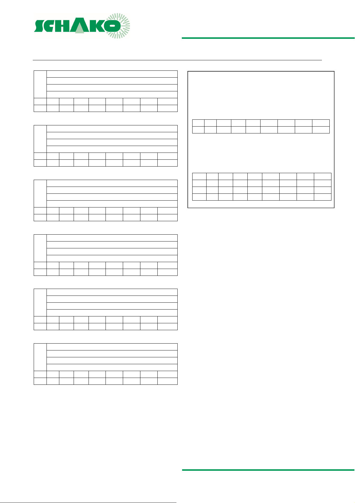
VLV65 - FLOW GENERATED NOISE - RELATIVE SOUND SPECTRUM
NW100
Relative sound spectrum (dB)
Correction value KL
Frequency (Hz)
Hz 63 125 250 500 1000 2000 4000 8000
KL -7 -8 -5 -2 -3 -12 -18 -25
NW125
Relative sound spectrum (dB)
Correction value KL
Frequency (Hz)
Hz 63 125 250 500 1000 2000 4000 8000
KL -9 -8 -5 -2 -3 -10 -17 -25
Size 160
Relative sound spectrum (dB)
Correction value KL
Frequency (Hz)
Hz 63 125 250 500 1000 2000 4000 8000
KL -7 -7 -3 -1 -4 -9 -17 -26
NW200
Relative sound spectrum (dB)
Correction value KL
Frequency (Hz)
Hz 63 125 250 500 1000 2000 4000 8000
KL -5 -3 0 -1 -6 -11 -18 -27
NW250
Relative sound spectrum (dB)
Correction value KL
Frequency (Hz)
Hz 63 125 250 500 1000 2000 4000 8000
KL -4 -2 1 -2 -6 -9 -16 -25
Size 315
Relative sound spectrum (dB)
Correction value KL
Frequency (Hz)
Hz 63 125 250 500 1000 2000 4000 8000
KL -1 0 1 -2 -5 -9 -16 -27
Differential pressure range: 0 - 300 Pa
Air velocity: 0.5 - 5.0 m/s
KL= correction value; relative sound power level, relative to LWA
KLW = LWA + {KL}
C A L C U L A T I O N E X A M P L E
VLV65 design data
NW 200 mm | V=545 m³/h |
p=100 Pa | L
Hz 63 125 250 500 1000 2000 4000 8000
KL -5 -3 0 -1 -6 -11 -18 -27
Sound values calculated according to formula
K
LW(relativ)
gives
Hz 63 125 250 500 1000 2000 4000 8000
LWA 60 60 60 60 60 60 60 60
KL -5 -3 0 -1 -6 -11 -18 -27
KLW 55 57 60 59 54 49 42 33
= 60 dB(A)
WA
= LWA + {KL}
Construction subject to change
No return possible Version: 2017-04-24 | Page 13
Page 14
VLV55|VLV65 - Volumetric flow controller
TECHNICAL DOCUMENTATION
VLV65 - Radiated noise |
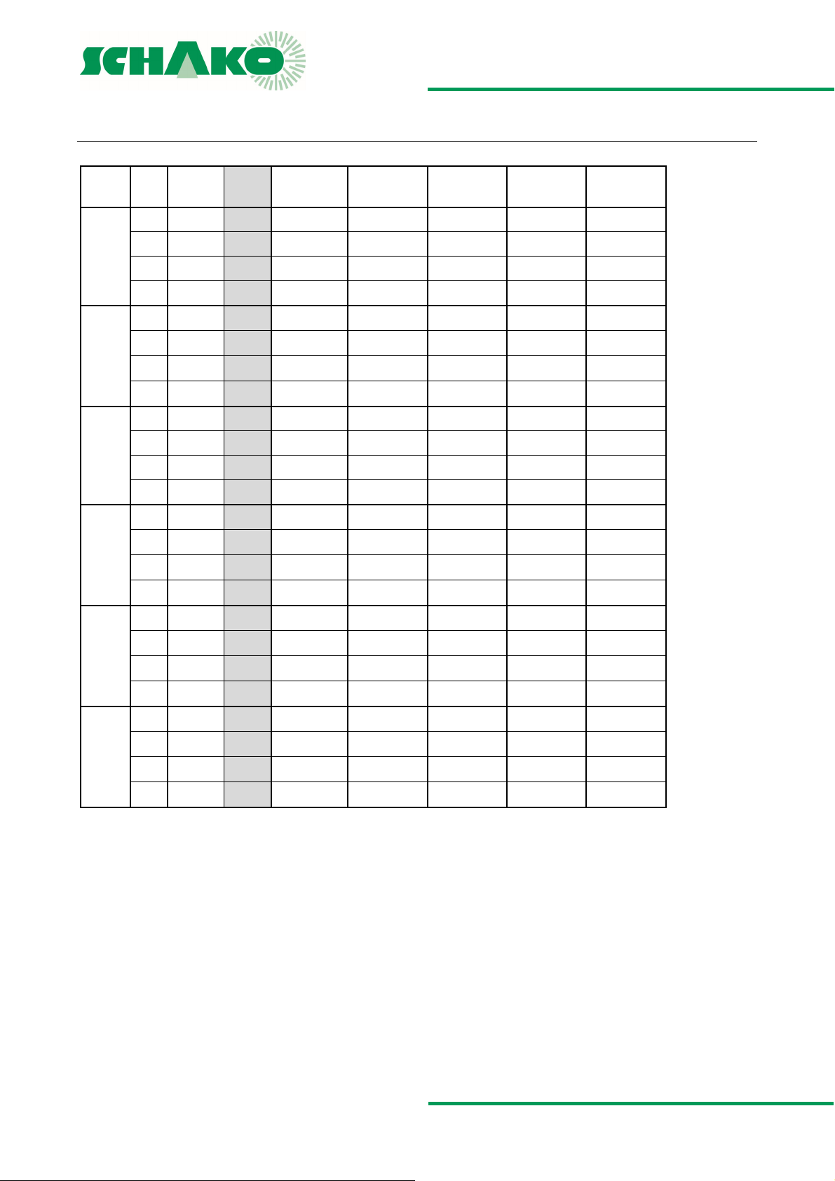
VLV65 - RADIATED NOISE
VLV65
NW
VK
(m/s)
V
(m3/h) V [l/s]
1 26 7
3 79 22
100
5 130 35
8 210 58
1 42
3 125 35
125
5 210 60
8 334 93
1 69
3 208 58
160
5 345 95
8 554 154
1 109 30
3 328 91
200
5 545 150
8 874 243
1 172 48
3 515 143
250
5 860 240
8 1374 382
1 274
3 823 229
315
5 1370 380
8 2195 610
--- = values below 25 dB(A)
12
19
76
∆pt = 50 Pa
[dB(A)]
L
WA
∆p
= 100 Pa
t
[dB(A)]
L
WA
--- ---
--- ---
--- 25
--- ---
--- ---
--- ---
--- 30
--- 38
--- ---
--- 33
--- 39
--- 44
--- 25
--- 35
--- 38
--- 43
--- 26
--- 37
--- 40
--- 45
--- 26
--- 38
--- 40
--- 47
∆p
= 150 Pa
t
L
WA
[dB(A)]
∆p
= 200 Pa
t
[dB(A)]
L
WA
∆p
= 250 Pa
t
[dB(A)]
L
WA
--- --- ---
26 28 30
30 32 35
35 39 40
--- --- ---
26 29 30
33 34 36
40 41 42
25 28 31
36 38 40
41 43 45
46 47 48
29 32 34
38 40 42
42 44 46
46 48 50
30 34 36
40 42 44
43 45 47
47 49 51
29 35 38
42 42 44
44 44 47
50 50 51
Construction subject to change
No return possible Version: 2017-04-24 | Page 14
Page 15
VLV55|VLV65 - Volumetric flow controller
TECHNICAL DOCUMENTATION
VLV65 - Radiated noise - relative sound spectrum |
VLV65 - RADIATED NOISE - RELATIVE SOUND SPECTRUM
NW100
Relative sound spectrum (dB)
Correction value KL
Frequency (Hz)
Hz 63 125 250 500 1000 2000 4000 8000
KL 1 0 -8 -6 -5 -5 -10 -13
NW125
Relative sound spectrum (dB)
Correction value KL
Frequency (Hz)
Hz 63 125 250 500 1000 2000 4000 8000
KL 2 1 -5 -2 -8 -7 -9 -12
Size 160
Relative sound spectrum (dB)
Correction value KL
Frequency (Hz)
Hz 63 125 250 500 1000 2000 4000 8000
KL 0 -1 -6 -4 -7 -7 -8 -10
NW200
Relative sound spectrum (dB)
Correction value KL
Frequency (Hz)
Hz 63 125 250 500 1000 2000 4000 8000
KL 0 -2 -6 -4 -7 -7 -7 -11
NW250
Relative sound spectrum (dB)
Correction value KL
Frequency (Hz)
Hz 63 125 250 500 1000 2000 4000 8000
KL -1 -2 -5 -6 -9 -6 -7 -12
Size 315
Relative sound spectrum (dB)
Correction value KL
Frequency (Hz)
Hz 63 125 250 500 1000 2000 4000 8000
KL 0 -2 -2 -6 -8 -6 -7 -19
Differential pressure range: 0-300 Pa
Air velocity: 0.5 – 5.0 m/s
KL= correction value; relative sound power level, relative to LWA
KLW = LWA + {KL}
C A L C U L A T I O N E X A M P L E
VLV65 design data
NW 200 mm | V=545 m³/h |
p=100 Pa | LWA = 38 dB(A)
Hz 63 125 250 500 1000 2000 4000 8000
KL 0 -2 -6 -4 -7 -7 -7 -11
Sound values calculated according to formula
K
gives
= LWA + {KL}
LW(relativ)
Hz 63 125 250 500 1000 2000 4000 8000
LWA 38 38 38 38 38 38 38 38
KL 0 -2 -6 -4 -7 -7 -7 -11
KLW 38 36 32 34 31 31 31 27
Construction subject to change
No return possible Version: 2017-04-24 | Page 15
Page 16
VLV55|VLV65 - Volumetric flow controller
TECHNICAL DOCUMENTATION
Duct silencer (-RS) - insertion loss |
DUCT SILENCER (-RS) - INSERTION LOSS
L1=500
(dB/Okt)
D
P=50 - f
125
250
m
500
NW
63
100 3 6 10 16 22 30 14 13 5 13 15 19 33 31 25 15
125 3 5 9 14 20 24 12 11 4 10 13 18 29 25 18 12
160 2 4 7 12 18 19 10 9 3 9 11 16 26 19 14 10
200 1 3 6 10 16 15 7 6 3 7 9 15 25 17 11 9
250 1 2 4 9 15 11 4 3 2 6 8 14 23 15 9 7
315 1 1 3 8 12 8 3 2 2 4 7 13 20 12 7 5
e
(Hz) P=100 - fm (Hz)
63
125
250
500
1000
2000
4000
8000
1000
2000
L1=950
(dB/Okt)
D
P=50 - f
125
250
m
500
NW
63
100 5 12 23 36 50 50 34 21 7 19 28 40 50 50 50 32
e
(Hz) P=100 - fm (Hz)
63
125
250
500
1000
2000
4000
8000
1000
2000
L1=1450
(dB/Okt)
D
P=50 - f
250
m
500
NW
63
4000
8000
100 8 22 44 50 50 50 46 28 - - - - - - - -
125 7 20 39 50 50 50 39 25 - - - - - - - -
160 6 14 27 42 48 42 26 18 6 17 30 47 50 49 30 18
200 4 6 15 29 42 30 17 14 5 14 26 42 50 46 28 16
250 3 4 10 20 37 24 13 11 4 12 22 36 46 43 25 14
315 2 4 8 16 34 19 10 7 2 8 15 27 35 32 17 9
125
e
(Hz) P=100 - fm (Hz)
63
125
250
500
1000
2000
4000
8000
1000
2000
4000
8000
L1=1950
(dB/Okt)
D
P=50 - f
250
m
500
NW
63
4000
8000
100 9 30 50 50 50 50 50 38 - - - - - - - -
125
e
(Hz) P=100 - fm (Hz)
63
125
250
500
1000
2000
4000
8000
1000
2000
4000
8000
125 4 11 21 33 50 50 32 19 6 17 25 34 49 50 36 22
160 3 8 15 23 34 9 18 14 5 12 18 28 41 48 26 16
200 2 5 11 18 30 24 14 11 4 10 15 24 35 41 22 13
250 2 4 9 15 27 18 11 9 3 8 13 20 31 35 20 11
315 1 3 6 12 24 14 7 6 2 6 8 15 26 7 14 8
P = packing thickness in mm
125 8 26 50 50 50 50 50 33 - - - - - - - -
160 - - - - - - - - 8 23 39 50 50 50 41 25
200 - - - - - - - - 7 19 34 50 50 50 37 21
250 - - - - - - - - 6 16 29 48 50 49 33 18
315 - - - - - - - - - - - - - - - -
Construction subject to change
No return possible Version: 2017-04-24 | Page 16
Page 17
VLV55|VLV65 - Volumetric flow controller
TECHNICAL DOCUMENTATION
Controller selection | Technical data of control components
control to a minimum volumetric flow
V
CONTROLLER SELECTION
Type Size Controller Product
LMV-D3-MP NW100 - 315 Compact Belimo
LMV-D3-MF NW100 - 315 Compact Belimo
227VM-024-05 NW100 - 315 Compact Gruner
Other controllers available on request. Make Belimo,
Gruner, Sauter, Siemens and Delta Controls possible.
TECHNICAL DATA OF CONTROL COMPONENTS
Measured value collection and control function
The volumetric flow controllers of the Belimo make, type LMVD3-MP/-MF Compact and the Gruner make, type 227VM Compact are delivered by SCHAKO as standard with the operating
mode (Y signal, U5 signal) 2-10 V DC. When activated by 2 V DC,
volume is controlled, the smallest possible V
the V
min
that can be controlled can be seen from the "Volumetric Flow
Range" tables.
NOTE: When the air volume drops below the V
min
table, the correct functioning of the volumetric flow controller
is no longer guaranteed!
Positive control damper "CLOSED"
Airtight sealing to DIN EN 1751 is achieved on site either via a
positive control "CLOSED" by means of a switch or a relay, or
via an actuator signal of 0 V DC applied to the input Y (all Compact controllers equipped with the operating mode 2-10V DC).
Accordingly, the drive will likewise close the flap in operating
range 2 - 10 V DC (however, this does not apply to the operating range 0-10 V DC), and the VAV control will be inactive. To
do so, it must be ensured that the actuator signal is < 0.1 V DC.
This is why in rooms where defined pressures are active (e.g. laboratories), the damper should be closed via a digital on site
switching contact.
If the Compact controllers of the Belimo make must be delivered with the operating mode 0-10V DC on customer request,
please note that a positive control "CLOSED" can only be effected via a switching contact with diode.
If the compact controllers of the Belimo make are used together with the type VRP-VFP-300 in the master/slave mode or
in parallel mode, then only the 2-10 V DC operating mode is
usually possible.
Positive control damper "OPEN"
Supports smoke extraction or is used as a safety position. The
volumetric flow controller is in this case inactive, and the
damper is driven to the mechanical open position.
volume
min
shown in the
min
Depending on requirement or by not assigning them, individual
areas can be set to stand-by operation. In this way, minimum
room flushing with greatly reduced energy expenditure is
achieved.
V
control to a maximum volumetric flow
max
Individual or several rooms are supplied for a short period with
a maximum volumetric flow. This allows, for example, a room
through-ventilation or efficient heating to be effected.
Continuous operation
As a function of the continuous driving signal and the programmed operating range (0-10 V DC or 2-10 V DC), the volumetric flow controller will regulate the volumetric flow linearly
...V
between the setpoint values V
min
max
.
Constant operation
If terminal 3 (Y driving signal) has not been assigned, the air volume set on the V
potentiometer will be set to a constant vol-
min
ume.
Two-stage volumetric flow rate control
Stage 1: If terminal 3 (Y command signal) has not been
assigned, the air volume set on the V
potenti-
min
ometer will be set to a constant volume.
Stage 2: If AC 24 V is applied to terminal 3 (Compact con-
troller) or terminal 7 (VRD3-SO, VRP-VFP-300),
the VSR will keep the value set on the V
max
potentiometer constant. With a switch or a contact
in a connection line a "secondary volume flow
control" is possible.
Construction subject to change
No return possible Version: 2017-04-24 | Page 17
Page 18
VLV55|VLV65 - Volumetric flow controller
}
TECHNICAL DOCUMENTATION
Circuit diagrams - Belimo |
CIRCUIT DIAGRAMS - BELIMO
Circuit diagram - standard - controller
Compact controller - Belimo make - LMV-D3-MP / LMV-D3-MF
VAV with analogue command signal VAV with lock (CLOSED) MP bus activation with integrated
DC
AC
switch- Model 2-10V DC (LMV-D3-MP only)
DC
AC
VAV command signal
DC
AC
VAV command signal
on site
Cable designations
CLOS
ED
MP / actual value signal
PC tool
No. Designation Wire colour Function
1
2
3
5
-
black
〦
+ ~ red ~ + AC/DC 24 V
Y white VAV / CAV command signal
U orange - Actual value signal
〦
CLOSED / VAV mode
VAV
switchover
MP / actual value signal
on site
-
- MP bus connection
PC tool
Feed
e.g.
window
contact
MP address:
1…8
on site
PC tool
Lock mode (CLOSED): In the 2…10 V
mode, the following function can be carried out with a 0 - 10 V signal.
Com-
nal Y
Volumetric
flow
Operating stage
min
... V
min
mand sig-
< 0.1 V ** 0 Damper CLOSED,
0.2...2 V V
2...10 V V
Function
VAV control inac-
tive
active
V
min
continuous opera-
max
tion
v
... V
min
max
**Attention: Controller/DDC must be able
to pull the command signal to 0 V.
Construction subject to change
No return possible Version: 2017-04-24 | Page 18
Page 19
VLV55|VLV65 - Volumetric flow controller
TECHNICAL DOCUMENTATION
Circuit diagrams - Belimo |
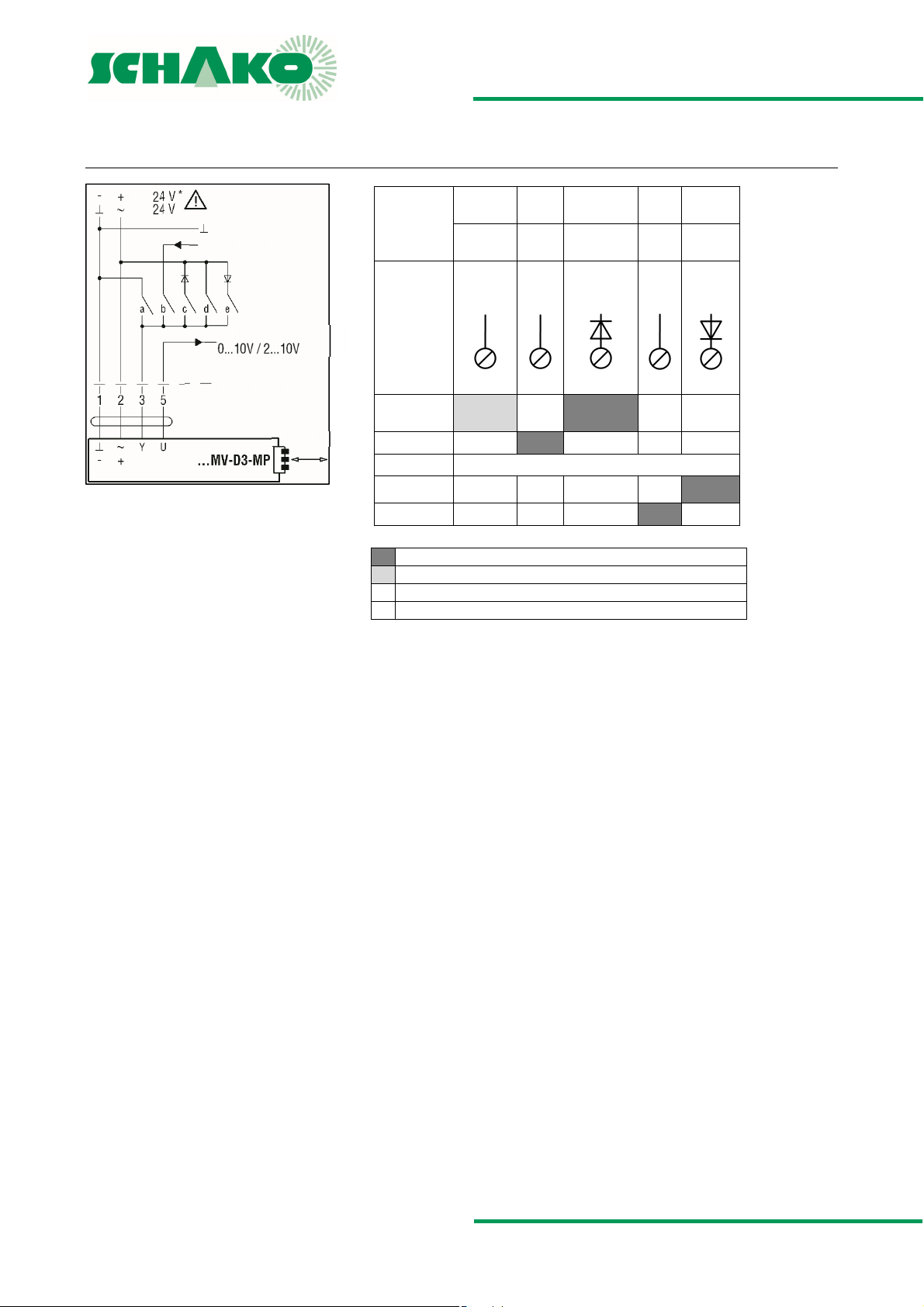
CAV operation / positive contacts CAV function for …-MV-D3-MP/-MF
DC
AC
VAV command signal
MP / actual value signal
on site
Note:
Please ensure mutual locking
of the contacts!
PC tool
Mode
setting
Signal
Function 33 3 3 3
Damper
CLOSED
V
...V
min
max
CAV - V
min
Damper OPEN e) OPEN*
CAV - V
max
--- 0...10 V 0...10 V
2...10 V 2...10 V 2...10 V
0...10 V
⊥
- 2...10 V +
a) CLOSED c) CLOSED*
b) VAV
everything open - V
∼
Contact closed, function active
Contact closed, function active, in mode 2...10 V only
Contact open
* not available for 24 V DC supply
min
0...10
0...10 V
V
2...10
2...10 V
V
∼
active
d) V
max
∼
Construction subject to change
No return possible Version: 2017-04-24 | Page 19
Page 20
VLV55|VLV65 - Volumetric flow controller
)
TECHNICAL DOCUMENTATION
Circuit diagrams - Belimo |
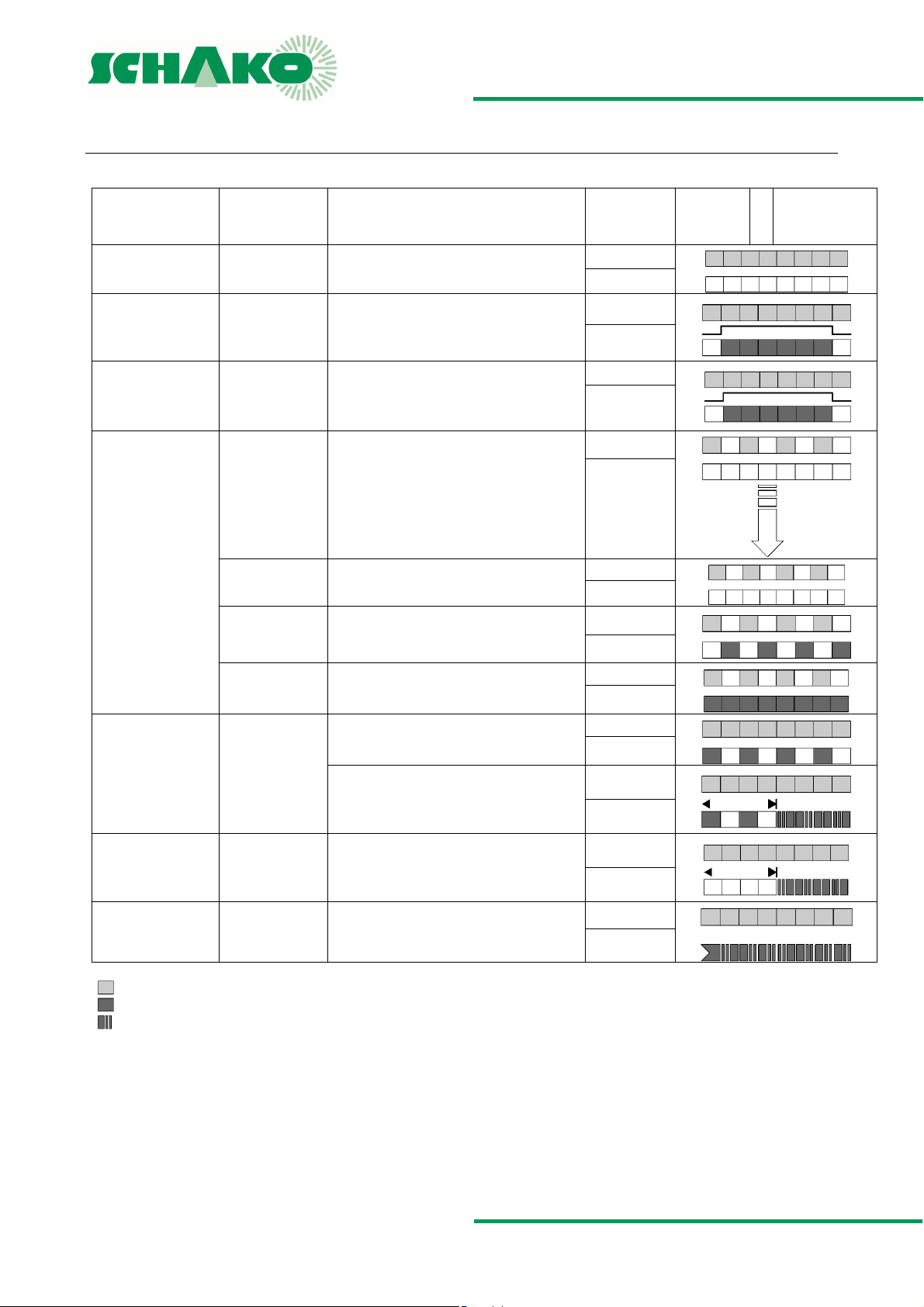
LED table of functions for LMV-D3-MP / LMV-D3-MF
Application
N1 operation Status display - 24 V power supply o.k.
S1 service function Synchronisation Synchronisation started by:
S2 service function Adaptation Adaptation started by:
Function
Description / action
- VAV-Compact ready for operation
a) Operating / service unit
b) Manual trigger device at the VAV-Compact
c) Power ON behaviour
a) Operating / service unit
b) Key on the VAV-Compact
LED pattern
LED 1
LED 2
LED 1
LED 2
LED 1
LED 2
Adaptation
Address
Start
Start
⊕
LED 1 power
LED 2 status
⊕
1.) →
→
2.
V1 VAV service VAV service
B1 bus operation Addressing via MP
B2 bus operation Addressing via MP
B3 bus operation
communication
active
Lack of air Damper opens as actual volume is too low LED 1
Target volume
reached
Air excess Damper closes as actual volume is too high LED 1
master
(Acknowledgement at the VAVCompact)
master (with serial number)
MP-PP display
Communication
green LED (power) is lit
yellow LED (status) is lit
yellow LED (status) is flashing
1.) Synch time
2.) Adaptation time
a) Press both keys «Adaptation» & «Address»
simultaneously
b) VAV service will be activated:
- until 24 V supply is switched off
- until both keys are pressed
again
- after 2 hours have passed
Control circuit balanced
a) Addressing has been triggered at the MP
master
b) Press addressing key
LED will switch to the communication display
as soon as the addressing process is complete.
Addressing at the MP master was triggered, LED
will switch to the communication display as soon
as the addressing process is complete.
Communication display via MP master or operating / service unit
LED 1
LED 2
LED 2
LED 1
LED 2
LED 2
LED 1
LED 2
LED 1
LED 2
LED 1
LED 2
LED 1
LED 2
On event
Not address.
MP communication
MP communication
MP communication
Construction subject to change
No return possible Version: 2017-04-24 | Page 20
Page 21
VLV55|VLV65 - Volumetric flow controller
TECHNICAL DOCUMENTATION
Circuit diagrams - Gruner |
CIRCUIT DIAGRAMS - GRUNER
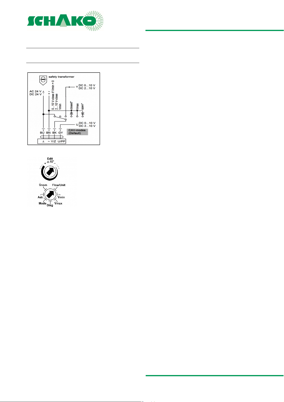
227VM-024-05 Compact
Connection diagram and positive control
Connection
Edit
The selector value allows values to be changed. The position of
the arrow shows the set value. The changes are displayed as
soon as the selector is moved ± 10 ° out of its position.
Flow / Unit
To set the required actual volumetric flow unit
in m3/h and l/s.
V
min
To set the required min. volumetric flow
(setpoint value Y = 0V / 2V)
V
max
To set the required max. volumetric flow
(setpoint value Y = 10V).
Mode (to set the direction of rotation)
0-n…0-10 V normal
2-n…2-10 V normal
0-i…0-10 V inverse
2-i…2-10 V inverse
Diag (diagnostics menu)
oP - opens the damper blade
cL - closes the damper blade
Hi - activates Vmax
Lo - activates Vmin
on - diagnostic mode is on, motor is off
oFF - diagnostic mode is off, display Y setpoint
V
nom
To set the volumetric flow according to VAV box
NOTE
Further information can be found in the GRUNER technical documentation:
Data sheet 227VM-024-05
Construction subject to change
No return possible Version: 2017-04-24 | Page 21
Page 22
VLV55|VLV65 - Volumetric flow controller
TECHNICAL DOCUMENTATION
Setting the operating potentiometers |
SETTING THE OPERATING POTENTIOMETERS
with calculation formulas
Set value for V
EW
V
max
The required volumetric flow that is to flow at the 10 V DC command signal at terminal 3 (w/Y) or with positive control V
set in % at the V
device or PC-Tool. This value refers to the set V
umetric flow.
Set value for V
EW
=
V
min
The required volumetric flow that is to flow at the 0 V DC command signal (operating mode 0-10 V DC) or at the 2 V DC driving signal (operating mode 2 - 10 V DC) at terminal 3 (wY) or
with positive control V
of the controller, the ZTH EU device or PC-Tool. This value refers to the set V
troller type).
Information regarding the set value V
in the following controllers, V
Product Type
Belimo LMV-D3-MP/LMV-D3-MF
Gruner 227VM-024-05
Calculation of the U5 voltage value
=
V
V
V
nenn
max
nenn
max
x 100 %
potentiometer of the controller, the ZTH EU
max
nenn
min
V
min
V
nenn
x 100%
max
is set in % at the V
min
or V
volumetric flow (depending on con-
max
refers to V
min
min
nenn
min
:
potentiometer
is
max
nominal vol-
Actual value measurement feedback signal U
: voltme-
5
ter / PC-Tool
LMV-D3-MP / LMV-D3-MF
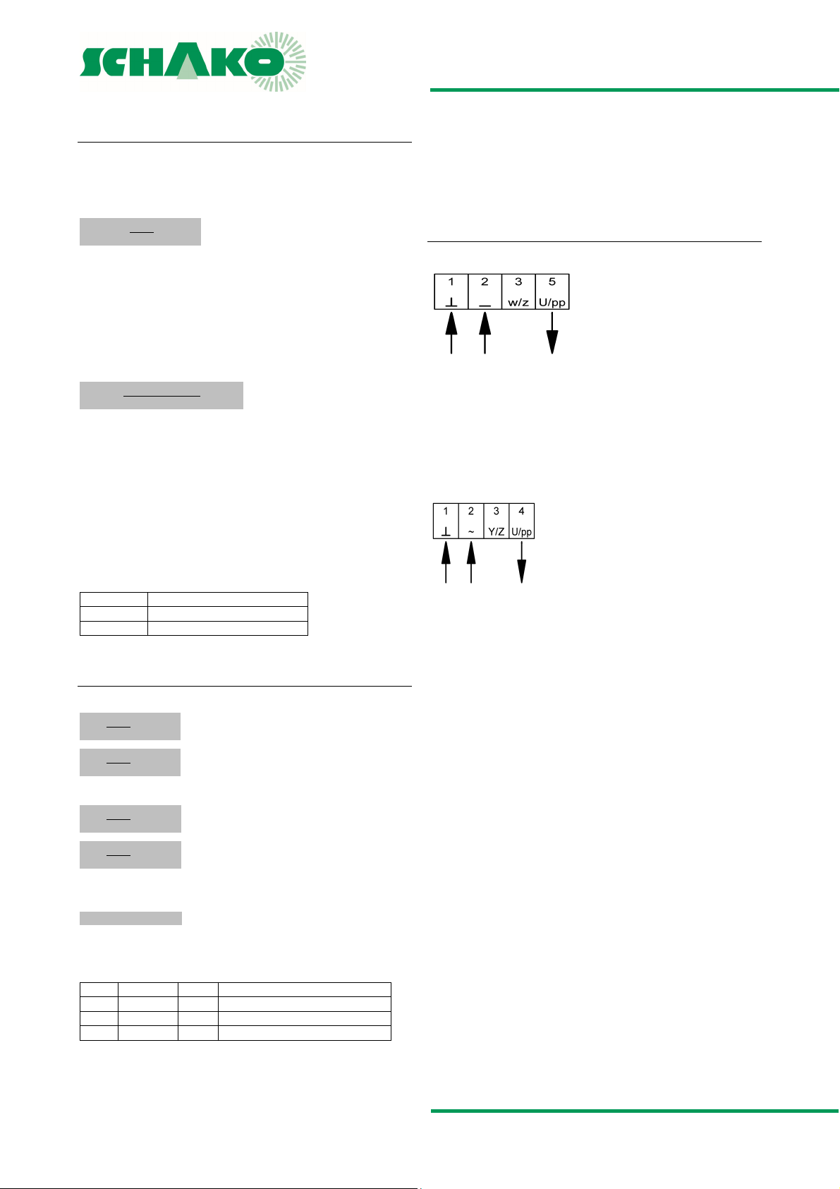
Supply voltage: 24 V AC/DC (terminals 1+2)
Measurement output 2 - 10 V DC (terminals 1+5)
Measurement output 0 - 10 V DC (terminals 1+5)
The actual value signal U5 is a real feedback of the volumetric
flow actual value for monitoring and controlling the air
throughput volume.
227VM-024-05
Supply voltage: 24 V AC/DC (terminals 1+2)
Measurement output 2 - 10 V DC (terminals 1+4)
Measurement output 0 - 10 V DC (terminals 1+4)
Operating mode: 2 - 10 V DC:
V
max
U5=
U5=
V
nenn
V
min
V
nenn
x 8V+2V
x 8V+2V
V
V
max
min
values
values
Operating mode: 0 - 10 V DC:
V
max
U5=
U5=
Calculation of the V
V
x 10V
V
nenn
V
min
x 10V
V
nenn
= EK x F x 3600
nenn
values
V
max
V
values
min
volumetric flow
nenn
Attention
The V
value changes as a function of the set calibration curve.
nenn
EW (%) = Set value
EK (m/s) = Calibration curve
U
(V DC) = U5 signal
5
F (m2) = Surface
Construction subject to change
No return possible Version: 2017-04-24 | Page 22
Page 23
VLV55|VLV65 - Volumetric flow controller
TECHNICAL DOCUMENTATION
Setting the operating potentiometers |
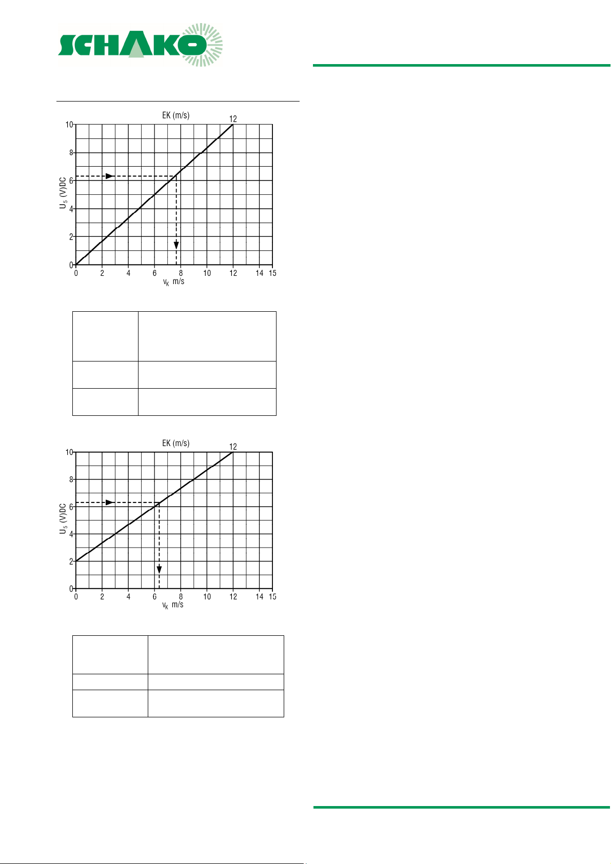
U5 signal 0-10 V DC
Example
Assume: Measurement output signal U5 =
6.3 V DC
see calibration value VRA-E = 12
m/sec
Measured value:
Air volume: Duct velocity x area m² x 3600 =
Duct velocity = 7.6 m/s
m³/h
U5 signal 2-10 V DC
Example
Assume: Measurement output signal U5 =
6.3 V DC see calibration value
VRA-E = 12 m/sec
Measured value: Duct velocity = 3.6 m/s
Air volume: Duct velocity x area m² x 3600 =
m³/h
Construction subject to change
No return possible Version: 2017-04-24 | Page 23
Page 24
VLV55|VLV65 - Volumetric flow controller
°
TECHNICAL DOCUMENTATION
Technical data of controllers and motors |
TECHNICAL DATA OF CONTROLLERS AND
MOTORS
Controller standard
LMV-D3-MP (make BELIMO)
Dynamic pressure sensor, digital VAV controller and damper drive as
communication-capable VAV-Compact solution.
Measuring principle: Pressure reading with volumetric flow
Measuring range sensor:
Supply voltage: AC 24 V 50/60 Hz; DC 24 V
Functional range: AC 19.2…28.8 V; DC 21.6…28.8 V
Power consumption: 2 W
Dimensioning: 3.5 VA
Torque: min. 5 Nm at the rated voltage
Control function: VAV/CAV/Open-Loop;
Setting range
V
:
min/Vmax
Command variable
w/Y:
(Input resistance min.
100 kΩ)
Setting range
Actual value signal U
MP bus function
Address
in bus mode:
LONWORKS®/EIBKonnex/MODBUS
RTU/BACnet:
DDC controller: DDC controller / PLC from different manu-
Fan Optimiser: with BELIMO Optimiser COU24-A-MP
Sensor connection: Passive (Pt1000, Ni1000, etc.) and active
Protection class: III (safety extra low voltage)
Protection type: IP 54 (hose-connected)
EMC: CE according to 39/336/EEC
Measuring air and
ambient temperatures:
Storage temperature: -20 °C… + 80 °C
Sound power level: max. 35 dB(A)
Operation and service:
Communication: PP/MP bus, max. DC 15V, 1200 baud
Connection: cable, 4x0.75 mm2, terminals
Weight: approx. 500 g
2…∼450 PA
Supply/return air or stand-alone operation;
master/slave parallel circuit;
Mixing box control
=0…100% of set V
V
min
V
=20…100% of set V
max
DC 2-10 V (4…20mA with 500 Ω
input resistance)
DC 0-10 V (0…20mA with 500 Ω
input resistance)
adjustable DC 0…10 V
DC 2…10 V
:
DC 0…10 V
5
1 … 8 (standard operation: PP)
with BELIMO interface UK24LON /
UK24EIB, 1 …8 BELIMO MP devices (VAV /
damper drive / valve)
facturers, with integrated MP interface
sensors (0…10 V), for example temperature, humidity, 2-point signal (switching
power 16 mA 24 V), for example switch,
presence detector
0° C…+50 °C, 5…95% rH,
non-condensing
plug-in via service socket / PC-Tool
(from V3.1) / ZTH EU
volumetric flow
nenn
volumetric flow
nenn
LMV-D3-MF (make BELIMO)
Dynamic pressure sensor, digital actuator as VAV-Compact solution
Measuring principle: Pressure reading with volumetric flow
Measuring range sensor:
Supply voltage: AC 24 V 50/60 Hz; DC 24 V
Functional range: AC 19.2…28.8 V; DC 21.6…28.8 V
Power consumption: 2 W
Dimensioning: 3.5 VA
Torque: min. 5 Nm at the rated voltage
Control function: VAV/CAV/Open-Loop;
Setting range
:
V
min/Vmax
Command variable
w/Y:
(Input resistance min.
100 kΩ)
Setting range
actual value signal U
Sensor connection: Passive (Pt1000, Ni1000, etc.) and active sensors
Protection class: III (safety extra low voltage)
Protection type: IP 54 (hose-connected)
EMC: CE according to 39/336/EEC
Measuring air and
ambient temperatures:
Storage temperature: -20°C…+80 °C
Sound power level: max. 35dB(A)
Operation and service:
Communication: PP, max. DC 15 V, 1200 baud
Connection: cable, 4x0.75 mm2, terminals
Weight: approx. 500 g
2…∼450 PA
Supply/return air or stand-alone operation;
master/slave parallel circuit;
Mixing box control
V
=0…100 % of set V
min
=20…100 % of set V
V
max
DC 2-10 V (4…20 mA with 500 Ω
input resistance)
DC 0-10 V (0…20 mA with 500 Ω
input resistance)
adjustable DC 0…10 V
DC 2…10 V
:
DC 0…10 V
5
(0…10 V), for example temperature, humidity, 2point signal (switching power 16 mA 24 V), for
example switch, presence detector
C…+50° C, 5…95 % rH, non-condensing
0
plug-in via service socket / PC-Tool
(from V3.1) / ZTH EU
volumetric flow
nenn
volumetric flow
nenn
Construction subject to change
No return possible Version: 2017-04-24 | Page 24
Page 25
VLV55|VLV65 - Volumetric flow controller
TECHNICAL DOCUMENTATION
Technical data of controllers and motors |
227VM-024-05 (make GRUNER)
Dynamic pressure sensor, digital VAV controller and damper
drive as communication-capable VAV-Compact solution.
Measuring principle: Pressure reading with volumetric flow
Measuring range sensor:
Supply voltage: AC 24 V 50/60 Hz, DC 24 V
Functional range: AC 19…29 V, DC 19…29 V
Power consumption: 2.5 W (5 Nm)
Dimensioning: 4.0 VA (5 Nm)
Torque: min. 5 Nm at the rated voltage
Control function: VAV/CAV
Setting range:
to V
max
V
min
Command variable Y/Z
(inherent resistance
min. 100 kΩ
)
Setting range:
(actual value signal
U/PP)
DCC controller: DCC controller or PLC
Sensor integration: passive or active sensor (0-10 V)
Protection class: III (Safety extra low voltage)
Protection type: IP54 (measuring hoses connected)
Measuring air and
ambient temperature
Storage temperature: -20 °C to +80 °C
Sound power level: <35 dB(A)
Operation and service: using the display by means of a screw-
Connection: cable 1000 mm, 4 x 0.75 mm
Dimensions:: 115 x 65 x 61 mm
Weight: approx. 435 g
Maintenance: maintenance-free
0…∼250 PA
(bursting pressure 1 bar)
(10 Nm, 15 Nm, optional)
Supply/return air or stand-alone operation;
master/slave parallel circuit
V
=0…100% of V
min
V
=0…100% of V
max
V
=0…100% of V
konst.
nom
nom
nom
DC 0-10 V (0-20 mA min. 500 Ω
inherent resistance)
DC 2-10 V (4-20 mA min. 500 Ω
inherent resistance)
DC 0-10 V
DC 2-10 V
for example, humidity, temperature
2-point signal (switching power 16 mA
24 V), for example switch, motion detector
0-70 °C (medium), 5-95 °C relative
0-50 °C (environment), humidity
non-condensing
driver directly at the device or via the
feedback signal with
PC software
2
(halogen-free), terminals
Construction subject to change
No return possible Version: 2017-04-24 | Page 25
Page 26
VLV55|VLV65 - Volumetric flow controller
TECHNICAL DOCUMENTATION
Startup using PC-Tool |
STARTUP USING PC-TOOL
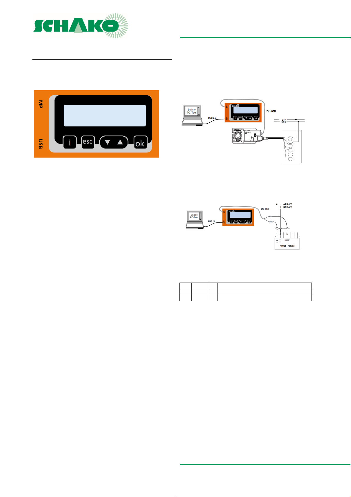
Direct connection to switch cabinet or socket
(traditional application)
ZTH EU as MP level converter
Description
The ZTH EU is also a potential-free interface between the USB
port of a PC and the Belimo MP bus. It is used to connect the
Belimo PC-Tool directly to the MP bus or directly to a programmable MFT drive.
Power supply
The ZTH EU is supplied with power by the USB port. The MP bus
voltage is obtained internally by means of DC/DC converter.
This is why no external power supply is necessary.
Driver
To be able to work with the ZTH EU, a suitable driver must be
installed on the PC. The driver can be downloaded from the
Belimo website (download section). After installation of the
driver, the ZTH EU device will log in to the PC as a virtual COM
interface.
Note
For connection to USB ports of PCs and BELIMO 24 V drives
only (to safety extra low voltage SELV or US class 2 feeds)
Connection diagram 1
…A-MF
…A-MP
…D3-MP
…ALON
…D3LON
Local connection via a service socket of the MF/MP or LON
drive using a ZK1-GEN cable.
Connection diagram 2
1.)
…MFT(2)
A-AF
…A-MP
…D3-MP
…LON
…ALON
…D3LON
Local connection via a connecting cable of the MF/MP or LON
drive using a ZK2-GEn cable.
1.) white = GND
green = MP
blue = not connected
Construction subject to change
No return possible Version: 2017-04-24 | Page 26
Page 27
VLV55|VLV65 - Volumetric flow controller
TECHNICAL DOCUMENTATION
Startup using the setting and diagnostic device ZTH EU (Belimo) |
STARTUP USING THE SETTING AND
DIAGNOSTIC DEVICE ZTH EU (BELIMO)
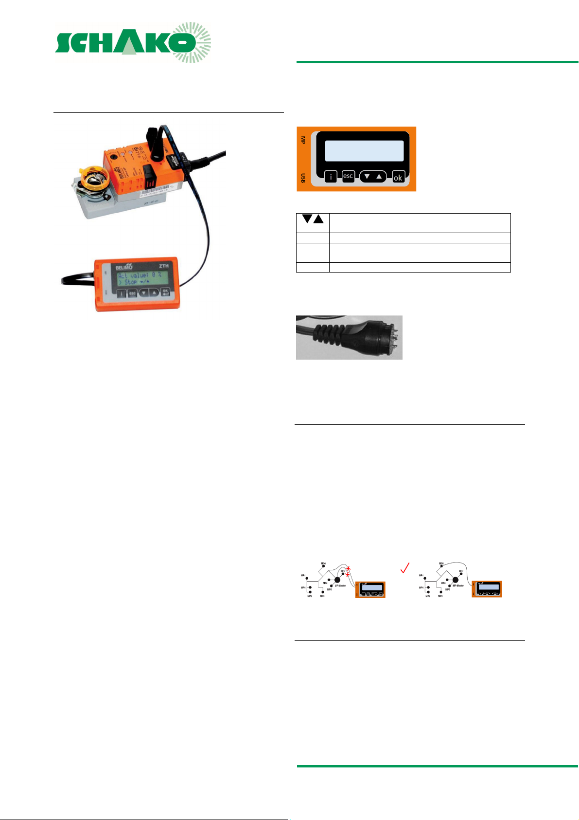
Keys / Display
Short description
The VAV setting device ZTH EU allows efficient testing of VAV
and CAV installations. Installations fitted with the Belimo VAV
controller can be simply adapted to the room and user requirements. The VAV setting device ZTH EU replaces the previous
setting device ZTH-GEN (2007-2014).
All standard Belimo VAV controllers with integrated PP communication (from 1992) that are sold in the EU can be set using the
ZTH EU.
Specifications
easy, quick setting of the VAV boxes parameters
diagnostic function
one tool for all VAV units
voltage supplied by VAV controllers - no batteries required!
service socket VAV / CR24 controller, PP connection
includes connecting cable RJ12 6/4, 6-pin plug
New generation, MP bus tester
for functional test of MP bus
backward compatible with all Belimo PP / MP units from
1992
efficient handling, can be operated with one hand
Selection of stages for test (OPEN/CLOSE/MIN/MAX/STOP)
Damper position indicator for diagnostics
Display of the setpoint / actual volume and V
m³/s (l/s).
min/max
setting in
2 x 16-digit LCD with background lighting
Forwards / Backwards
Change value / status
OK Confirm input
ESC Cancel input /
i shows additional information if available
Connection
Locally via service socket
Dimensions
85x65x23 (WxHxD)
Leave submenu / Discard changes
Connection and supply
Stand-alone operation
Connection including supply takes place via the service socket
at the VAV controller or via the terminals.
Bus operation
The ZTH EU can be used in the following units while the bus is
running if it is connected via the local service socket: VAVCompact L/N/SMV-D3-MP, NMVAX-D3-MP, L/NMV-D3LON.
With the VRP-M, L/NMV-D3-M and NMVAX-D3-MP, the MP-Bus
must be disconnected when the service socket is used.
Restriction
Direct connection in an MP network or via an MP-Bus master is
not possible.
The ZTH EU comes with a quick start guide in German and English to be affixed to the back of the unit.
Construction subject to change
No return possible Version: 2017-04-24 | Page 27
Page 28
VLV55|VLV65 - Volumetric flow controller
TECHNICAL DOCUMENTATION
Startup using the setting device GUIV-A | Smartphone app - Belimo Assistant
STARTUP USING THE SETTING DEVICE GUIV-A
SMARTPHONE APP - BELIMO ASSISTANT
Application
The setting device GUIV-A is used by the startup or service personnel in order to carry out simple settings to the equipment or
to check the actual values.
The controller type 227VM does not have any operating elements such as switches or setpoint potentiometers. To program
the operating modes and the operating parameters V
V
, the setting device GUIV-A is required, which can also be
max
min
and
used to switch from 2 - 10 V DC to 0 - 10 V DC.
Connection
The GUIV-A can be connected electrically to 227 V via the U/PP
connection by direct on site or remote control, for example in a
switch cabinet.
Structure and operation
The relevant parameters can be set and queried in the individual menu items, while the operating parameters programmed
in-factory can be queried under menu item 10.
Note
As long as the U/PP connector is connected to the GUIV-A, the
output signal U does not correspond to the actual value.
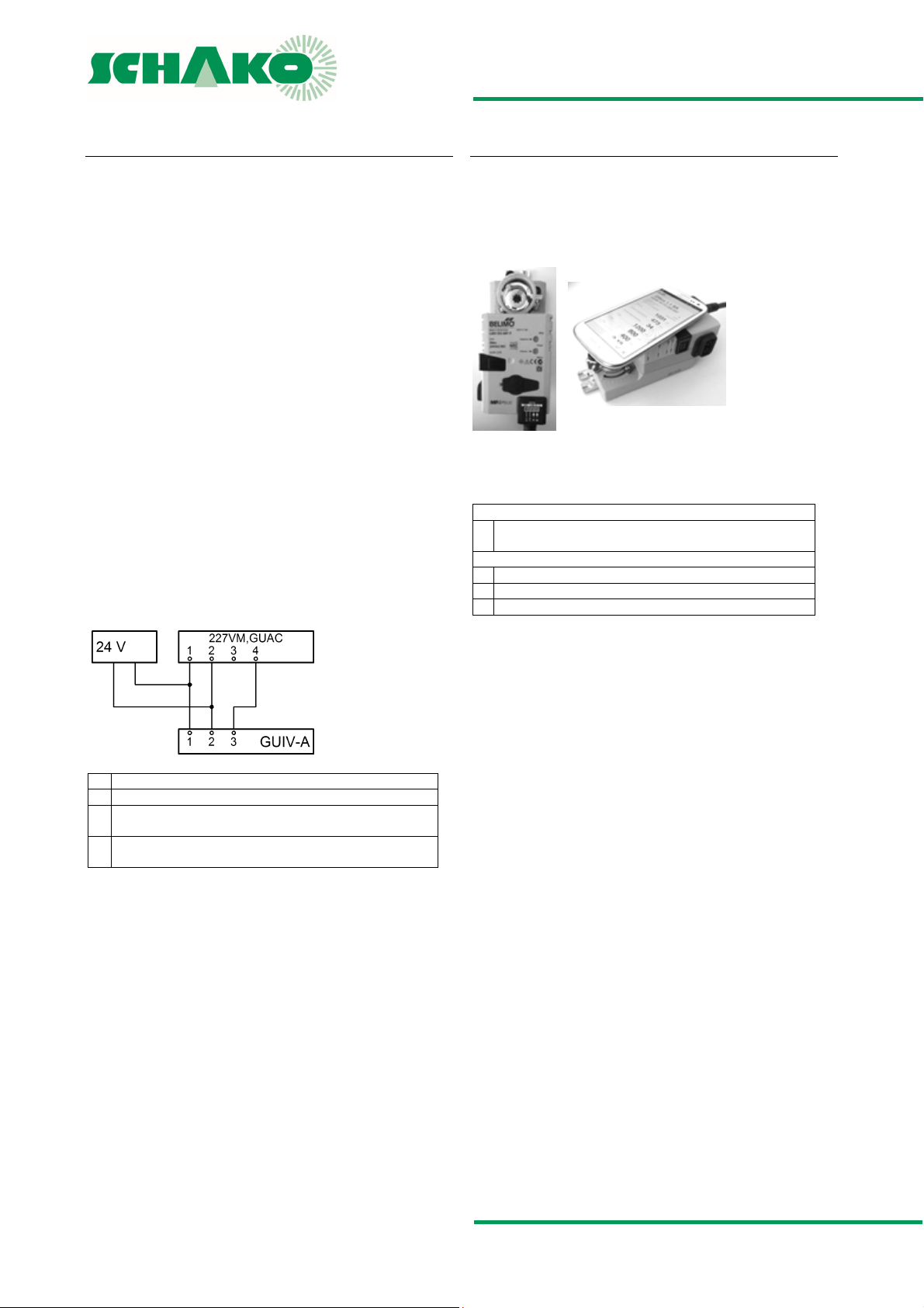
Connection diagram
The NFC antenna area of the VAV Compact is located between
the Belimo or OEM logo and the NFC label.
Align NFC-capable android smartphone with loaded Assistant
app on the VAV-Compact such that the two antennae are
above one another.
The Belimo Assistant app can be downloaded from the Google
Play Store.
NFC-capable devices:
- LMV-D3-MP, NMV-D3-MP, SMV-D3-MP and LHV-D3-MP with
printed NFC label.
Non-NFC-capable devices
- All devices without NFC label
- LMV-D3-MF
- LMV-D3-LON and NMV-D3-LON
1 Earth, neutral
2 Supply voltage 24 V AC
3 Setpoint value signal Y and positive control Z input 227VM,
GUAC
4 Output communication signal PP and actual volumetric flow
U
Construction subject to change
No return possible Version: 2017-04-24 | Page 28
Page 29
VLV55|VLV65 - Volumetric flow controller
TECHNICAL DOCUMENTATION
Prior to assembly and commissioning | Legend
PRIOR TO ASSEMBLY AND COMMISSIONING
LEGEND
An instruction leaflet containing
information on safety, transport disposal, installation
commissioning and maintenance is
enclosed with each SCHAKO product.
For safety reasons, this instruction
leaflet must
e read under all circumstances and
completely adhered to.
These devices are NOT suitable for use in zones where there is
a risk of explosion according to ATEX 94/9/EC. The operating
safety of the devices is only guaranteed when used in accordance with their designated use.
Disposal
The devices have been prepared in accordance with the RoHS
directive restricting the use of certain hazardous substances in
electrical and electronic equipment (2002/95/EC). After its final
decommissioning, the volumetric flow controller must be
properly disposed of.
INSTALLATION INFORMATION
De [dB/Okt] = Insertion loss
EK (m/s) = Calibration curve
fm (Hz) = Octave band centre frequency
V
(m³/h) [l/s] = Minimum volumetric flow
min
V
(m³/h) [l/s] = Maximum volumetric flow
max
Hz (fm) = Hertz
KL (-) = Correction value; relative
sound power level, relative to LWA
(-)
K
Lw
LOA (-) = Number of holes in flat flange
P (mm) = Packing thickness duct silencer
NW (mm) = Nominal width
U
5
V (m3/h) [l/s] = Air volume
V [%] = Tolerance for the volumetric flow setpoint
vK (m/s) = Duct velocity
øD (-) = Hydraulic diameter
∆p (Pa) = Pressure difference
∆p
∆pt (Pa) = Pressure loss
(V) DC = Measurement output (electric voltage)
(Pa) = Minimum static pressure difference
t min
= Relative sound spectrum
value
Installation and commissioning
Installation with horizontal or vertical damper axle possible
position-independent
direct connection to moulded parts, such as bend or T-piece
possible
MAINTENANCE AND SERVICE
Service and maintenance instructions
Assemble in a way to allow inspection
maintenance-free, as there is no wear
not suitable for air containing sticky and oily particles
For maintenance, service, retrofitting, etc., inspection open-
ings in sufficient number and size must be provided on site.
Construction subject to change
No return possible Version: 2017-04-24 | Page 29
Page 30
VLV55|VLV65 - Volumetric flow controller
TECHNICAL DOCUMENTATION
Order code |
ORDER CODE
01 02 03 04 05 06 07 08
Type Size Material
Example
VLV55 -100 -SV -A001 -0 0020 -0100 -GD1
VLV65 -200 -DD -A061 -2 0150 -0600 -MF1
SAMPLE – VLV55
VLV55-100-SV-A001-0020-0100-GD1
Volumetric flow controller type VLV55, size 100 mm, galvanised
sheet steel, with compact controller Belimo LMV-D3-MP-SO,
mode 0 - 10 V, setting values 20 - 100 m³/h, with rubber lip seal
ORDER DETAILS
01 - Type
VLV55 = version with diameter ratio 55, 0.5 - 5 m/s
VLV65 = version with diameter ratio 65, 1 - 8 m/s (STANDARD)
02 - Size
100 = NW 100 mm
125 = NW 125 mm
160 = NW 160 mm
200 = NW 200 mm
250 = NW 250 mm
315 = NW 315 mm
03 - Material
SV = galvanised sheet steel (STANDARD)
DD = DD coating
04 - Attachment assembly
A001 = LMV-D3-MP-SO, 5 Nm - (STANDARD)
A006 = LMV-D3-MF-SO, 5 Nm
A061 = 227VM-024-05, 5 Nm
other controllers available on request
Attachment assembly
Mode
Volumetric flow
Vmin
SAMPLE – VLV65
VLV65-200-DD-A061-0150-0600-MF1
Volumetric flow controller type VLV65, size 200 mm, galvanised
sheet steel, with DD coating, with compact controller GRUNER
227VM-024-05, setting values 150 - 600 m³/h, with METU
flange
05 - Mode
0 = 0 - 10 V
2 = 2-10 V (STANDARD)
06 - Volumetric flow set value V
0000 = ex works, see table p. 5
1234 = 4-digit customer value in m³/h
07 - Volumetric flow set value V
0000 = ex works, see table p. 5
1234 = 4-digit customer value in m³/h
08 - Duct connection: GD or flange
KA0 = without rubber lip seal/without flange
GD1 = with rubber lip seal (STANDARD)
FF1 = flat flange, galvanised sheet steel
MF1 = METU flange, galvanised sheet steel
Either with GD or flange. Combination is not possible!
Volumetric flow
Vmax
min/Vkonst
max
Duct connection
Construction subject to change
No return possible Version: 2017-04-24 | Page 30
Page 31

VLV55|VLV65 - Volumetric flow controller
TECHNICAL DOCUMENTATION
Specification text |
SPECIFICATION TEXT
VLV55 | VLV65
Volumetric flow controller in round design, for round ductwork
connection, for use in supply and return air systems for constant or variable volumetric flow regulation.
Measurement of the volumetric flows according to the Venturi
principle. Standardised Venturi nozzle with measuring points
for differential pressure measurement in front of the nozzle
and in the nozzle neck. This ensures high control accuracy at
low air velocities, duct pressures and any inflow conditions.
Nozzle and differential pressure sensor are resistant to pollution. Connecting pipe is suitable for air ducts to DIN EN 1506.
Position of the control damper is visible from outside.
Leakage at the damper blade to DIN EN 1751, class C.
Housing leakage to DIN EN 1751, class 4.
Special features
designed for use at low air velocities and duct pressures
position-independent installation possible
high controlling precision with any inflow
resistant to pollution
Materials of housing and internal parts
Housing made of galvanised sheet steel (-SV)
Damper blade seal made of EPDM, silicone- and halogen-free
Ring chamber sealing made of EPDM, silicone- and halogen-
free
Venturi nozzle made of aluminium, with attached measuring
points for determining average values to DIN EN ISO 5167.
Technical data
Nominal sizes 100 - 315 mm
Volumetric flow range 13 - 2195 m³/h (4 - 610 l/s) approx. 10
- 100 % of nominal volumetric flow
Minimum pressure difference of 5 - 150 Pa
Allowed static differential pressure range: 20 - 750 Pa
Allowed ambient temperature 0 - 50 °C
For use with duct velocities of 0.5 - 8 m/s (depending on the
nozzle variant)
Add-on parts
Electronic compact controller suitable for individual control or
connection to a building control system. If required, in BUScapable design (LON, Modbus RTU, KNX, BACnet).
Supply voltage 24 V AC/DC, 50/60 Hz
wired and parameterised ex works
controller with potentiometer and display for subsequent ad-
justment on request
, V
possible positive controls: CLOSED, V
It is possible to subsequently adjust the manufacturer set op-
eration volumetric flow.
Product: SCHAKO type VLV
Housing, damper blade and measuring sensor at an extra
charge with DD coating (-DD)
min
max
, OPEN
Accessories (at an extra charge)
METU flange (-MF1), on both sides, duct flange type AF.
Flat flange (-FF1), on both sides, to DIN 24154/5.
Rubber lip seal (-GD1), on both sides, made of special rubber.
Duct silencer (-RS), rigid design, casing and perforated sheet
made of galvanized sheet steel with mineral wool filling
Construction subject to change
No return possible Version: 2017-04-24 | Page 31
 Loading...