

Page 1
SCHAKO | Ferdinand Schad KG Telephone +49 (0) 7463-980-0
Steigstraße 25-27 Fax +49 (0) 7463-980-200
D-78600 Kolbingen www.SCHAKO.de | infoSCHAKO.de
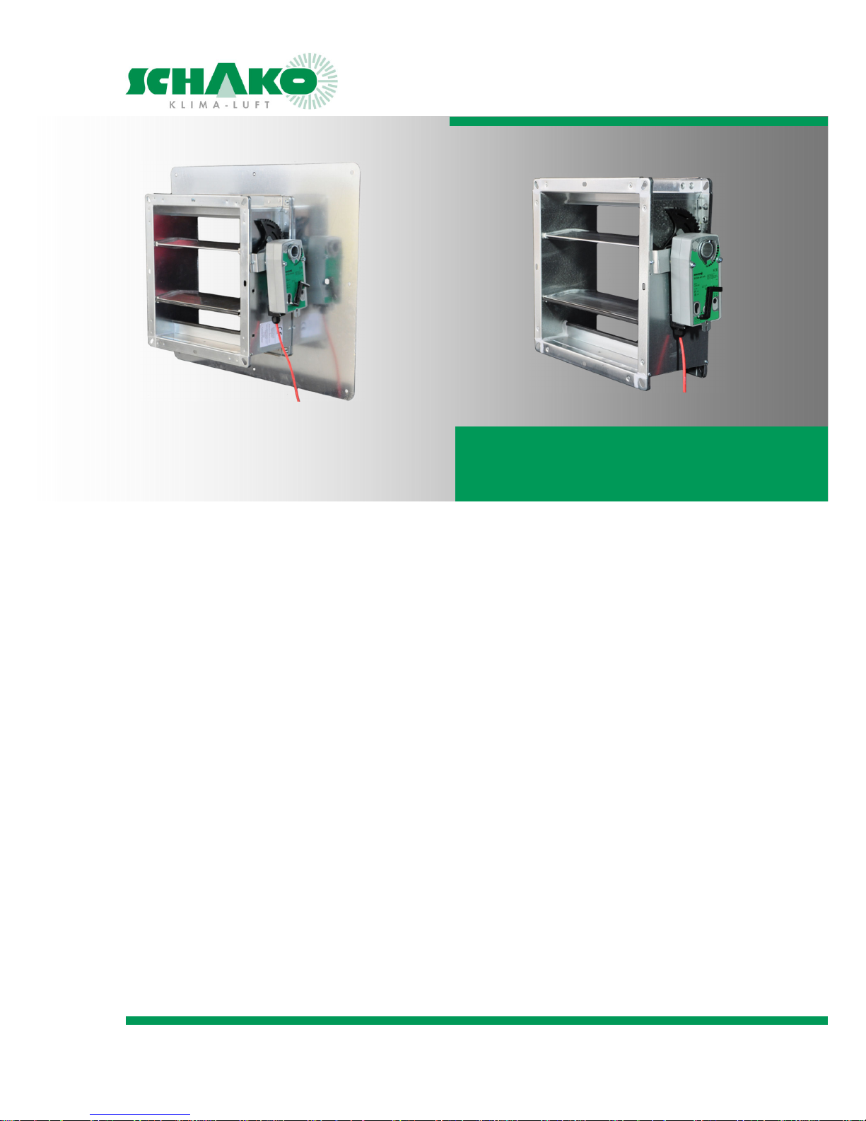
JK-180MB | JK-190
Natural smoke and heat exhaust ventilator
Contents
Function .................................................................. 2
Areas of application and requirements .................. 2
Capacity and classification ...................................... 3
Processing ............................................................... 4
Model JK-180MB / JK-190 ....................................... 5
Drives JK-180MB / JK-190 ....................................... 6
Accessories ............................................................. 7
Cross-sections and opening surface areas .............. 8
Dimensions JK-180MB ............................................ 9
Dimensions JK-190 ................................................ 10
Installation information ........................................ 11
Installation JK-180MB ........................................... 12
Installation JK-190 ................................................. 12
Installation accessories JK-190 ............................. 13
Weather protection hood ..................................... 16
Specification texts ................................................. 18
Order details ......................................................... 19
CE marking ............................................................ 20
Prior to assembly and commissioning .................. 21
Maintenance and function ................................... 21
Declaration of Performance
09-53-DoP-JK-180MB-2014-11-01
09-53-DoP-JK-190-2014-11-01
EC Certificate of Conformity
1368-CPD-C-004/2013
Performance Reliability Certificate
1368-CPR-C-7050
Technical documentation
Page 2

NRWG Multi-Leaf Damper Models JK-180MB / JK-190
Technical documentation
Function | Areas of application and requirements
Construction subject to change
No return possible Version: 2016-08-02 | Document: 09/53 | Page 2
FUNCTION
A natural smoke and heat exhaust ventilator (NRWG) is an
important part of a smoke and heat exhaust ventilation system (RWA). In case of fire, it is used to remove hot gases
from a building in order to protect people, material property
and the environment.
In case of fire, smoke and heat exhaust ventilation systems
are supposed to ensure a smoke-free layer near the floor by
removing a sufficient amount of the smoke gas from the
smoke section. Moreover, in the initial fire, their function is
to remove the hot smoke gases released by the fire.
The use of smoke and heat exhaust ventilation systems for
creating smoke-free areas under a stable smoke layer is a
recognised smoke removal practice. It keeps rescue routes
free from smoke, thus assisting the evacuation of people. At
the same time, this method can reduce the damage and financial losses caused by the fire. Moreover, this smoke removal method facilitates the fire department's work:
by improving visibility
by removing the heat from the roof area
and by delaying horizontal fire propagation.
This is why a smoke and heat exhaust ventilation system
(RWA) constitutes an important safety device that serves for
preventive fire protection and must therefore be subjected
to regular tests and maintenance. The NRWG described in
this brochure is used as an integral part of an RWA overall
system.
"EN 12101-2 Smoke and heat control systems, Part 2: Specification for natural smoke and exhaust ventilators" specifies
the requirements of an NRWG and regulates the test methods for natural smoke and exhaust ventilators in the roof
and façade areas.
Application range according to DIN 18232-2
"This standard applies to the measurement and installation
of natural smoke removal systems (NRA) for rooms with vertical smoke removal via the roof by thermal buoyancy according to DIN 18232-1 for single-storey buildings and the
top floor of multi-storey buildings. This standard also applies
to the measurement and installation of NRA for rooms with
horizontal smoke removal through exterior walls. This standard contains information and definitions that have to be observed when applying these measurement rules and installing NRA."
Measurement basis according to 18232-2
"The measurement of natural smoke removal systems (NRA)
depends on the energy release rate, the calculated fire surface area or measurement group and on the desired thickness of the low-smoke layer and on the room height.
The calculated values given for determining the abovementioned influence variables are auxiliary variables for
measurement and serve exclusively for measurement as
specified in this standard.
AREAS OF APPLICATION AND
REQUIREMENTS
The multi-leaf dampers JK-180MB and JK-190 are suitable as
natural smoke and exhaust ventilator for installation in the
façade area (wall) and roof area1) (ceiling).
REQUIREMENTS
of NRWG systems according to EN 12101-2:
Trigger element
Trigger devices must be used that either must be connected
to a smoke detector according to EN 54-7 or heat detectors
according to EN 54-5 or a different electrical signal that responds to smoke or heat.
Furthermore, prEN 12101-9 and EN 12101-10 must be observed.
Opening mechanism
Each NRWG is equipped with an opening mechanism - spring
return actuator or direct current actuator.
Opening of NRWG
According to EN 12101-2, the NRWG corresponds to type B
and can be opened to assume its functional position and
closed again by remote control.
Inputs and outputs
Inputs and outputs must be present in order to connect the
NRWG to the control panel according to EN 12101-9 and
power supplies according to EN 12101-10.
-------------
1)
Installation in a flat roof or slightly inclined roof (max. 10°)
with 500 mm flat-roof plinth and mounted louvre hood or
roof hood
Page 3
NRWG Multi-Leaf Damper Models JK-180MB / JK-190
Technical documentation
Capacity and classification |
Construction subject to change
No return possible Version: 2016-08-02 | Document: 09/53 | Page 3
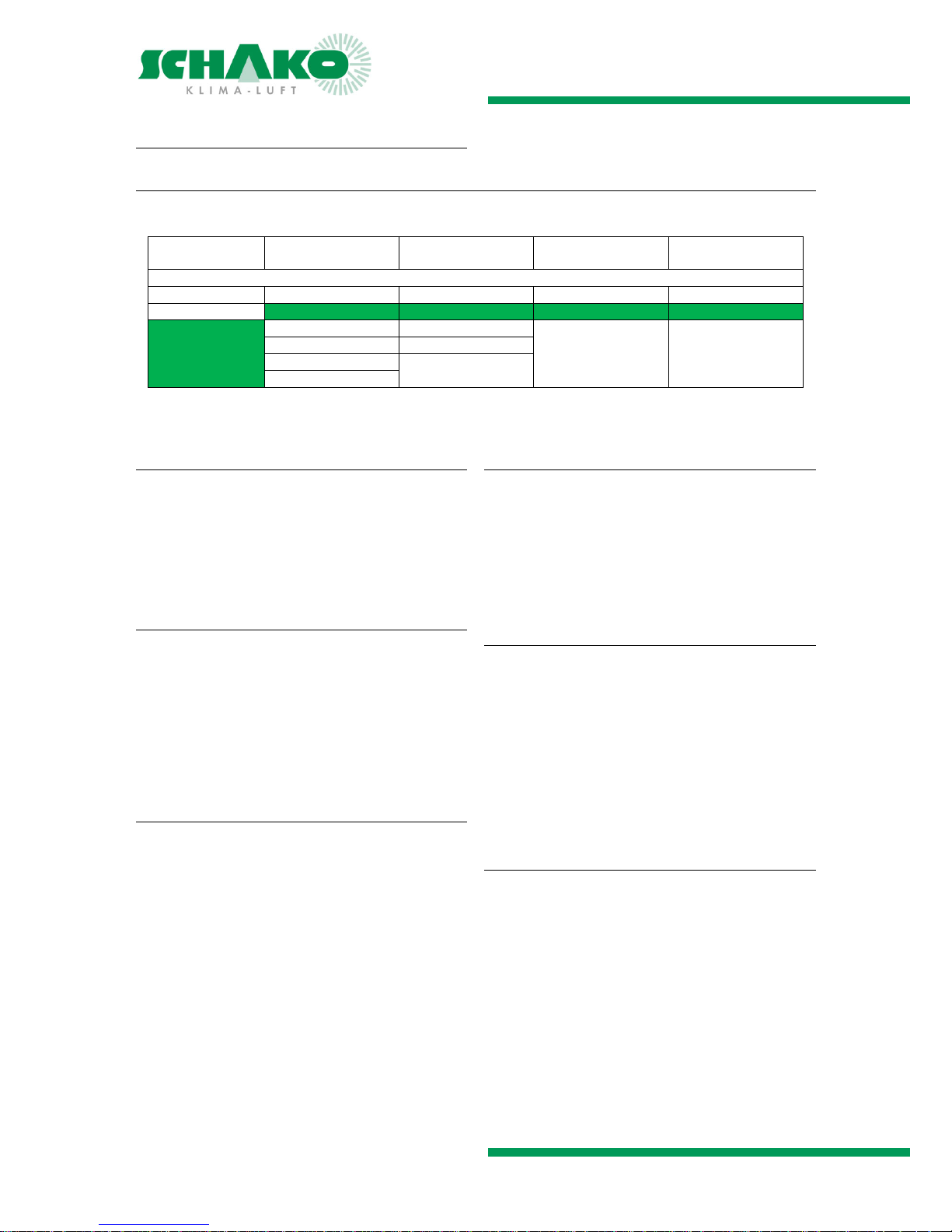
CAPACITY AND CLASSIFICATION
Summary
The classifications for JK-180MB / JK-190 are highlighted in colour.
Operational safety Snow load Low
ambient temperature
Wind load Resistance to heat
Possible classes according to DIN EN 12101-2
Re A* SL A* T A* WL A* B A*
Re 50 SL 0 T 0°C WL 1500 B 300
Re 1000 SL 125 T -5°C WL 3000 B 600
SL 250 T -15°C
SL 500 T -25°C
SL 1000
*) A is used as wild card for a certain value specified by the manufacturer
Aerodynamically active opening area
Geometric opening area multiplied by the flow rate coeffi-
cient
Flow rate coefficient determined experimentally either di-
rectly or indirectly from the test results of NRWGs of different sizes or from scaled-down models
Operational safety
Proof that the NRWG opens and closes during the number
of specified cycles
The designations A, 50 and 1000 indicate how often the
NRWG was opened in the initial test without external load.
The functional position must be reached within 60 °sec.
When used additionally for ventilation purposes, the func-
tional test must not be carried until the NRWG has been
opened 10,000 times in the ventilation position.
Snow load
Proof that the NRWG opens and remains open under wind
and snow loads
Indicates the test snow load in Pa (N/m²) applied when the
opening process is tested.
When the inclination of the recommended minimum in-
stallation angle exceeds 45°, the NRWG may be assigned
to class SL 0.
Low ambient temperature
Proof of reliable functioning of the opening mechanism of
the NRWG at lower temperatures
Indicates the temperature in °C at which the NRWG will be
tested
NRWGs are suitable for use in buildings in which the tem-
peratures exceed 0 °C.
For T(00), no low temperature test is required.
Wind load
Proof that the NRWG when exposed to wind load remains
intact, remains closed and can be opened to assume its
functional position after the exposure to the wind load is
over.
Indicates the test load (wind load) in Pa applied during the
test
When exposed to the relevant wind load, the NRWG must
not open and not exhibit any permanent deformation.
Following the test, it must open within 60 sec. after being
actuated.
Resistance to heat
Proof that the installed NRWG when exposed to fire will
open within 60 sec. to assume its functional position and
remain there.
Indicates the temperature in °C at which the NRWG will be
tested
Page 4

NRWG Multi-Leaf Damper Models JK-180MB / JK-190
Technical documentation
Processing |
Construction subject to change
No return possible Version: 2016-08-02 | Document: 09/53 | Page 4
PROCESSING
Housing
Profiled galvanised sheet steel 1.5 mm
Dimensionally stable
JK-180MB - for flush-mounted installation
with 180 mm frame depth and mounting plate
JK-190 - for surface-mounted installation
with 190 mm frame depth
Bores for fastening the accessories
Blades
Hollow-body aluminium blades
Flow-favouring and torsion-resistant
Jointly adjustable in opposite directions
Seal
EPDM rubber profile
Bearings
Sintered bearing
Gear wheels
Plastic PA6
Arranged on one side
The flow-favouring aluminium blades are jointly adjusted
in opposite directions via external plastic gear wheels
A cover plate protects the gear wheels from external con-
tamination and reduces the risk of injury to persons during
assembly and maintenance
Temperature resistance
Temperature-resistant 0 °C…+80 °C
Operational safety up to +300 °C according to EN 12101-2
Allowed ambient temperature actuator -20 °C to +50 °C
REMARK
The plastic PA6 has the property of changing its dimensions
as a function of the relative humidity. The gear wheels are
preconditioned for normal climate 23 °C, 50% of relative
humidity. If the multi-leaf damper is to be used in rooms in
which the relative humidity is permanently <20% or >80%, it
is recommended using stainless steel gear wheels made of
V2A instead of plastic gear wheels. Extra charge upon request.
NOTE
For maintenance, service, retrofitting, etc., the required ac-
cess must be ensured on site.
Page 5
NRWG Multi-Leaf Damper Models JK-180MB / JK-190
Technical documentation
Model JK-180MB / JK-190 |
Construction subject to change
No return possible Version: 2016-08-02 | Document: 09/53 | Page 5
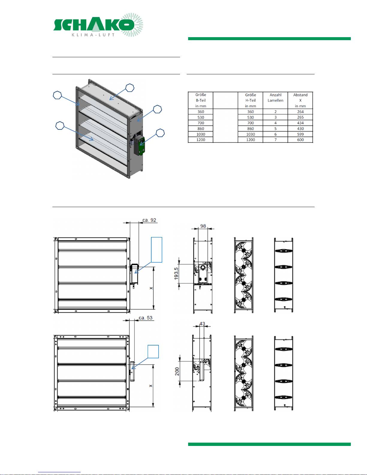
MODEL JK-180MB / JK-190
Components of the multi-leaf damper
Size chart
B and H components can be freely selected
1 = Housing (B part)
2 = Housing (H part)
3 = Actuator side (gear wheel cover)
4 = Actuator
5 = Blade
Views and cross-sections
Front view Drive side Gear wheels Blades
1
2
3
4
5
E70
E71
E24
E25
E72
E73
Page 6
NRWG Multi-Leaf Damper Models JK-180MB / JK-190
Technical documentation
Drives JK-180MB / JK-190 |
Construction subject to change
No return possible Version: 2016-08-02 | Document: 09/53 | Page 6
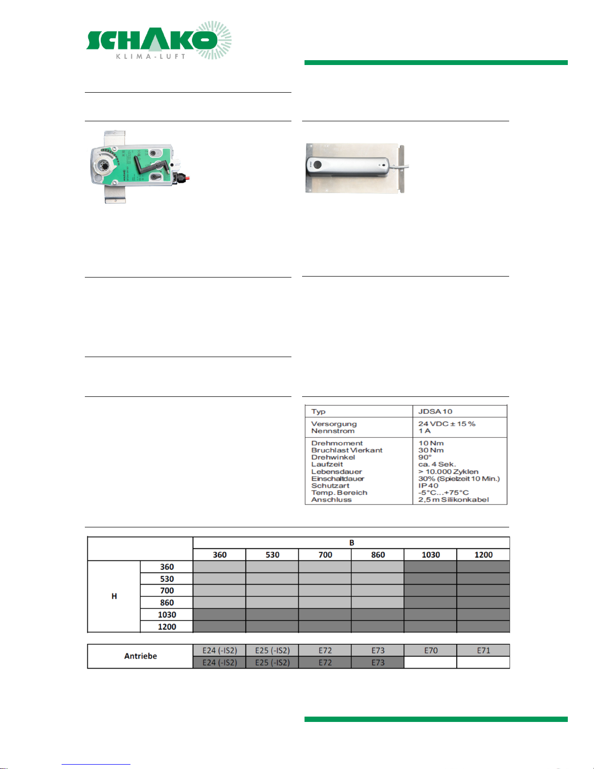
DRIVES JK-180MB / JK-190
ACTUATOR
Spring return actuator with emergency control function (currentless open) for adjusting air dampers. For use in openings
for smoke removal and for daily ventilation operation.
Suitable for interior assembly only.
Electrical, with spring return (currentless OPEN)
20 Nm, 230 V AC, 2/3-point (-E24)
20 Nm, 24 V AC, 2/3-point (-E25)
20 Nm, 24 V AC/DC, 0-10 V DC with RJ45 plug(-E72)
20 Nm, 24 V AC/DC, 0-10 V DC (-E73)
Electrical, with integrated limit switches (accessories)
2 limit switches CLOSED and OPEN (-IS2)
Technical data
Technical data and circuit / connection diagrams can be
found in the current technical documentation of the Belimo
drive.
DIRECT-CURRENT ACTUATOR
Actuator for electromotive opening and closing of NRWG
multi-leaf dampers. For use in openings for smoke removal
and in daily ventilation operation.
Suitable for interior assembly only.
Electrical, as DC motor
10 Nm, 24 V DC (-E70)
10 Nm, 24 V DC with RJ45 plug (-E71)
Technical data
Actuator selection
Page 7

NRWG Multi-Leaf Damper Models JK-180MB / JK-190
Technical documentation
Accessories |
Construction subject to change
No return possible Version: 2016-08-02 | Document: 09/53 | Page 7
ACCESSORIES
JK-180MB
Mounting plate (-MB)
Preassembled
For flush-mounted installation
Galvanised sheet steel 1.5 mm
Fastening materials
- Allen screw
- Washer
- Cage nut
Wall anchor package 1 (-M1)
Fastening material for fastening mounting plate to masonry
Anchor bolt
Sealing tape
Spacer sleeves
O-ring
JK-190
Wall anchor package 2 (-M2)
Fastening material for fastening multi-leaf damper to mason-
ry
Anchor bolt
Sealing tape
Spacer sleeves
O-ring
Wall anchor package 3 (-M3)
Fastening material for fastening accessories to masonry
Anchor bolt
Sealing tape
Spacer sleeves
O-ring
Support sheet (-AB)
Sheet metal bracket serves for offsetting the fastening holes
to avoid chipping on the wall edge
2-part
Galvanised sheet steel 1.5 mm
Not preassembled
Incl. screw package for fastening to the NRWG damper
Mounting bracket edge mounting (-EBW-R-H) / (-EBW-R-B)
Mounting bracket for fastening to ceiling on three sides and
for fastening to wall on one side (definition H or B side)
2-part
Galvanised sheet steel 1.5 mm
Preassembled, but not fastened to the multi-leaf damper
Incl. screw package for fastening to the NRWG damper
Mounting bracket corner mounting (-EBW-E-L)/(-EBW-E-R)
Mounting bracket for fastening to ceiling on two sides and
for fastening to wall on two sides
2-part
Galvanised sheet steel 1.5 mm
Preassembled, but not fastened to the multi-leaf damper
Incl. screw package for fastening to the NRWG damper
NOTE
Screw package 1
for B and H dimensions <1030 mm
- M6 screws
- M6 cage nuts
- M6 U-washers
- M6 nuts
Screw package 2
for B or H dimensions <1030 mm
- M6 screws
- M6 cage nuts
- M6 U-washers
- M6 nuts
WEATHER PROTECTION HOOD
Design as plinth with roof hood or louvre hood
Condensate channel with drain pipe in plinth part
Bird protection grille on the entire ventilation surface area
Galvanised sheet steel 1.2 mm
Plinth spot welded
Hood spot welded and riveted
Page 8
NRWG Multi-Leaf Damper Models JK-180MB / JK-190
Technical documentation
|
Construction subject to change
No return possible Version: 2016-08-02 | Document: 09/53 | Page 8
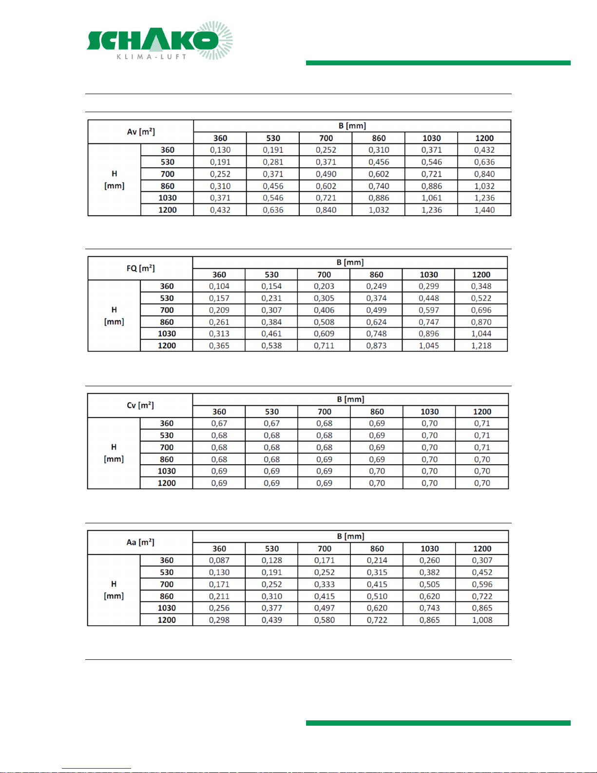
Cross-sections and opening surface
CROSS-SECTIONS AND OPENING SURFACE AREAS
GEOMETRIC OPENING SURFACE AREA (AV)
FREE CROSS-SECTION (FQ)
FLOW RATE COEFFICIENT (CV)
AERODYNAMICALLY ACTIVE OPENING SURFACE AREA (AA)
AERODYNAMICALLY ACTIVE OPENING SURFACE AREA WITH WEATHER PROTECTION HOOD
When using the NRWG multi-leaf damper with weather protection hood, the value of the aerodynamically active opening surface area of the weather protection hood must be taken into account.
Page 9
NRWG Multi-Leaf Damper Models JK-180MB / JK-190
Technical documentation
Dimensions JK-180MB |
Construction subject to change
No return possible Version: 2016-08-02 | Document: 09/53 | Page 9
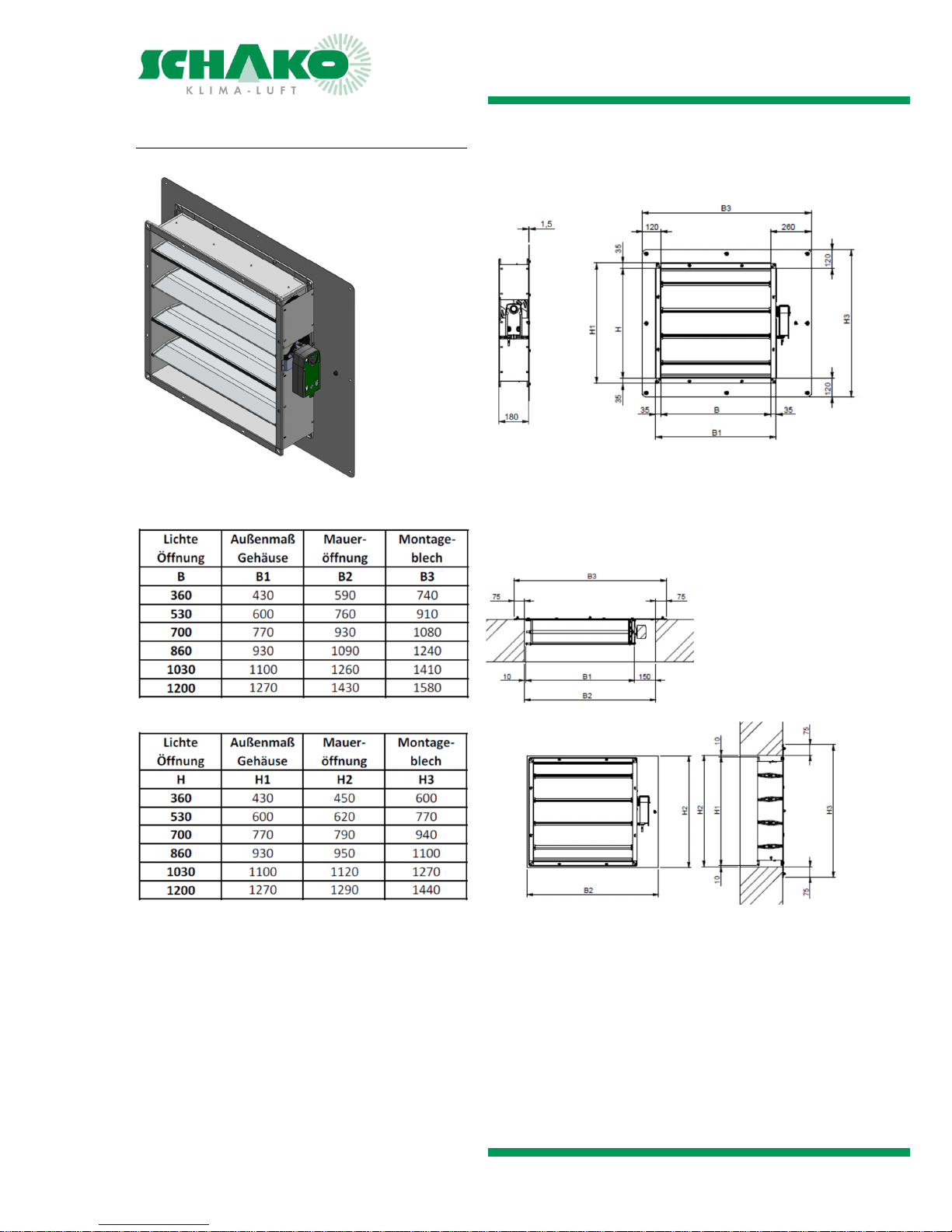
DIMENSIONS JK-180MB
Page 10
NRWG Multi-Leaf Damper Models JK-180MB / JK-190
Technical documentation
Dimensions JK-190 |
Construction subject to change
No return possible Version: 2016-08-02 | Document: 09/53 | Page 10
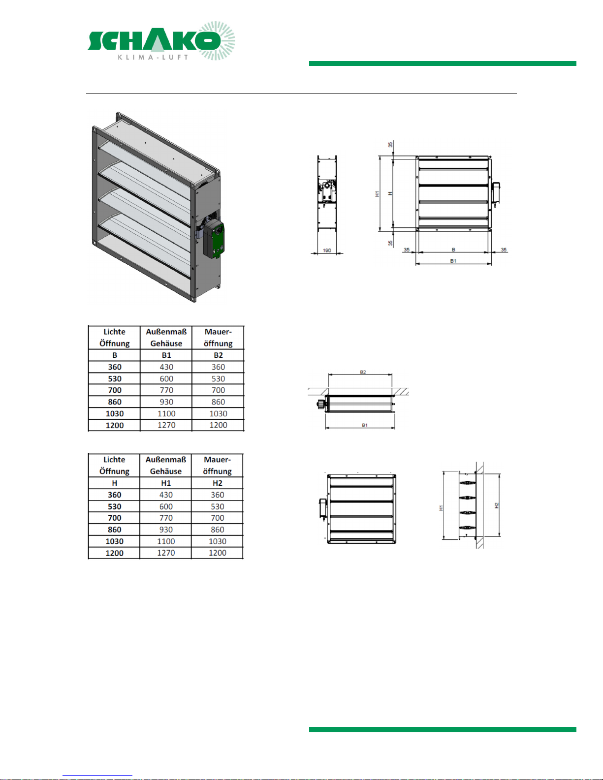
DIMENSIONS JK-190
Page 11
NRWG Multi-Leaf Damper Models JK-180MB / JK-190
Technical documentation
Installation information |
Construction subject to change
No return possible Version: 2016-08-02 | Document: 09/53 | Page 11
INSTALLATION INFORMATION
The multi-leaf dampers must not be tilted during installation.
Otherwise, this may result in problems with the adjustment
mechanism or in leaks.
The multi-leaf dampers are delivered in open position (currentless OPEN) and must be mounted as such.
NRWGs must be installed such that external forces do not
impair their permanent functioning.
They must be fastened by means of suitable mounting materials approved by the building supervisory authorities (see
Accessories) in accordance with the mounting instructions.
Protection from weather conditions must be guaranteed on
site!
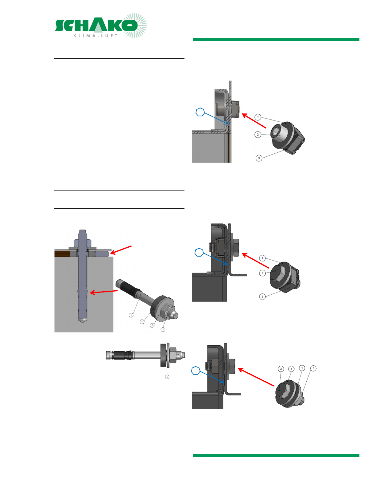
Fastening materials
Multi-leaf damper / Accessories - Masonry
Anchor bolt: drilling depth = 75 mm; drilling diameter =
8 mm
1 = Anchor bolt
2 = Washer
3 = Hexagon nut
4 = Spacer disc
5 = O-ring
Multi-leaf damper – Mounting plate (JK-180MB)
1 = Washer
2 = Allen screw
3 = Cage nut
4 = Sealing tape
Multi-leaf damper - Accessories (JK-190)
B and H sides
1 = Washer
2 = Allen screw
3 = Cage nut
4 = Sealing tape
Corner
1 = Washer
2 = Allen screw
3 = Hexagon nut
4 = Sealing tape
4
4
4
Sealing tape
Page 12
NRWG Multi-Leaf Damper Models JK-180MB / JK-190
Technical documentation
Installation JK-180MB | Installation JK-190
Construction subject to change
No return possible Version: 2016-08-02 | Document: 09/53 | Page 12
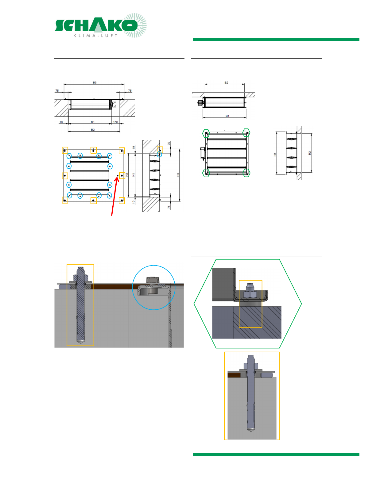
INSTALLATION JK-180MB
Fastening points
If required, the connecting cable of the actuator must be run
through the opening provided in the mounting plate and fastened using the cable traction relief premounted on the
connecting cable.
Detail
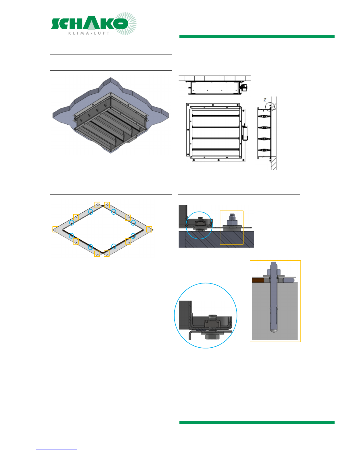
INSTALLATION JK-190
Fastening points
Detail
Page 13
NRWG Multi-Leaf Damper Models JK-180MB / JK-190
Technical documentation
Installation accessories JK-190 |
Construction subject to change
No return possible Version: 2016-08-02 | Document: 09/53 | Page 13
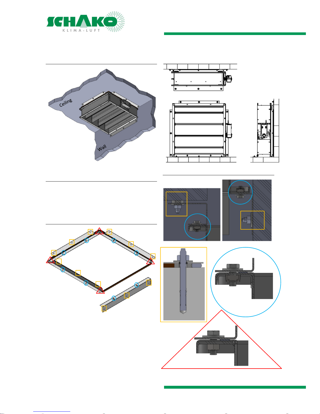
INSTALLATION ACCESSORIES JK-190
Support sheet (-AB)
Fastening points
Detail
Page 14
NRWG Multi-Leaf Damper Models JK-180MB / JK-190
Technical documentation
Installation accessories JK-190 |
Construction subject to change
No return possible Version: 2016-08-02 | Document: 09/53 | Page 14
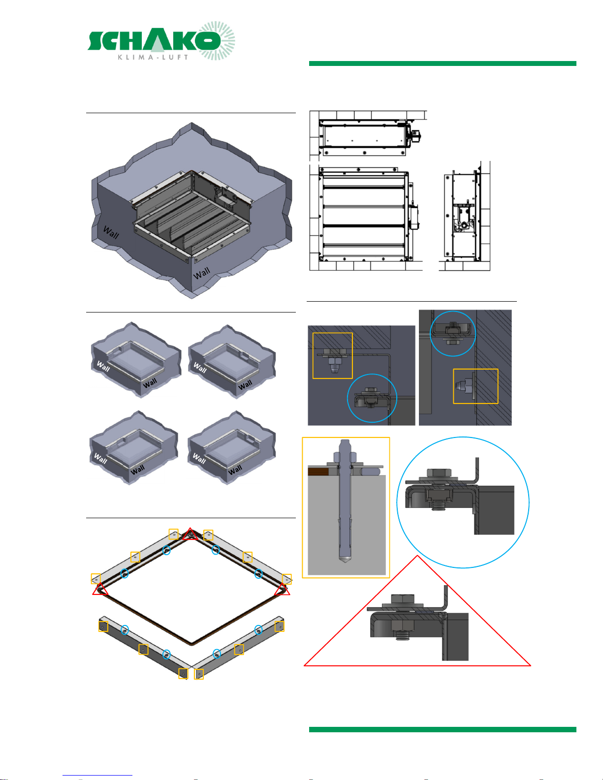
Mounting bracket edge mounting (-EBW-R-H) /
(-EBW-R-B)
shown: -EBW-R-B
Selection
EBE-R-H fastened to the wall via the bracket on
the H part of the multi-leaf damper (opposite side of the
actuator)
EBW-R-B fastened to the wall via the bracket on one of
the two B parts of the multi-leaf damper
Fastening points
Detail
Page 15
NRWG Multi-Leaf Damper Models JK-180MB / JK-190
Technical documentation
Installation accessories JK-190 |
Construction subject to change
No return possible Version: 2016-08-02 | Document: 09/53 | Page 15
Mounting bracket corner mounting (-EBW-E-L)/
(-EBW-E-R)
Selection (viewing direction from inside to outside
-EBW-E-R -EBW-E-L
-EBW-E-R -EBE-E-L
Fastening points
Detail
Ceiling
Ceiling
Ceiling
Ceiling
Ceiling
Page 16
NRWG Multi-Leaf Damper Models JK-180MB / JK-190
Technical documentation
Weather protection hood |
Construction subject to change
No return possible Version: 2016-08-02 | Document: 09/53 | Page 16
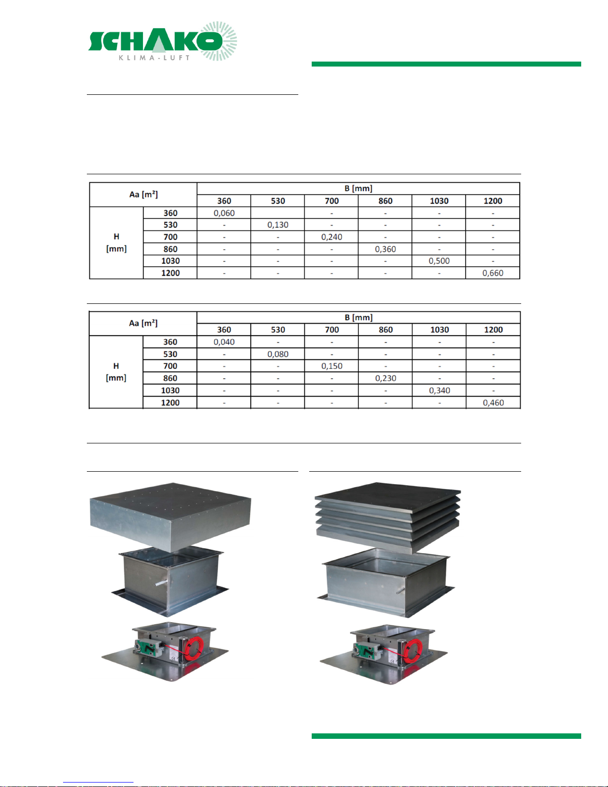
WEATHER PROTECTION HOOD
Flat-roof plinth with connection point on multi-leaf damper
Roof hood or louvre hood as weather protection
Access possible to NRWG for maintenance and actuator replacement
To be mounted before attaching the thermal roof insulation (connection to insulation on site)
AERODYNAMICALLY ACTIVE OPENING AREA - ROOF HOOD
AERODYNAMICALLY ACTIVE OPENING AREA - LOUVRE HOOD
MODELS
Roof hood
Louvre hood
Page 17
NRWG Multi-Leaf Damper Models JK-180MB / JK-190
Technical documentation
Weather protection hood |
Construction subject to change
No return possible Version: 2016-08-02 | Document: 09/53 | Page 17
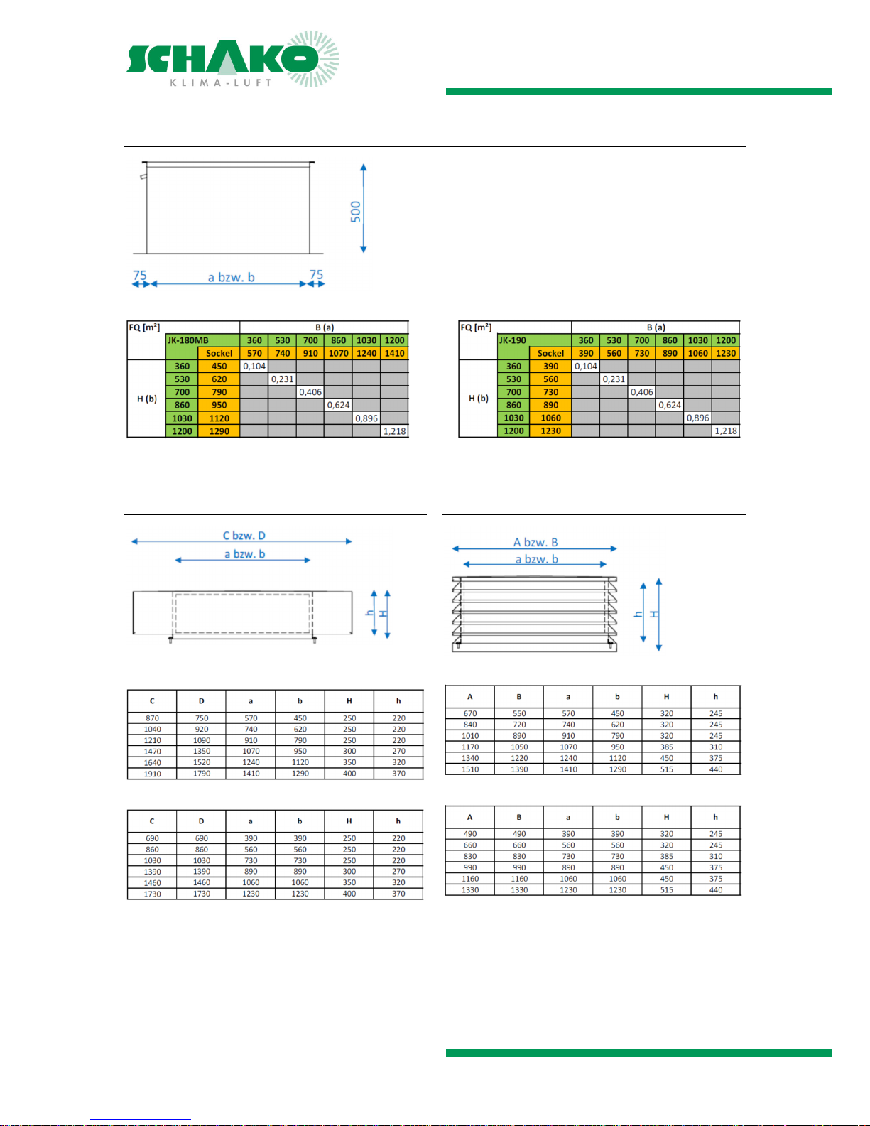
Plinth design
rectangular (JK-180MB) square (JK-190)
Other dimensions on request
Hood design
Roof hood
rectangular (JK-180MB)
square (JK-190)
Louvre hood
rectangular (JK-180MB)
square (JK-190)
Page 18

NRWG Multi-Leaf Damper Models JK-180MB / JK-190
Technical documentation
Specification texts |
Construction subject to change
No return possible Version: 2016-08-02 | Document: 09/53 | Page 18
SPECIFICATION TEXTS
JK-180MB
NRWG multi-leaf damper, housing leakage class C and leakage with closed damper leaf class 3 to DIN EN 1751, consisting of a dimensionally stable profiled frame made of 1.5 mm
galvanised sheet steel, frame depth 180 mm with joint flowfavouring hollow-body blades adjustable in opposite directions made of torsion-resistant aluminium profile.
The blades are adjusted by means of external plastic gear
wheels arranged on one side.
With sintered bearing
TÜV inspected according to VDI 6022 Sheets 1+2 and DIN
EN1751
With mounting plate for flush-mounted installation in wall
and ceiling
2)
Electric actuator with spring return (currentless OPEN)
20 Nm, 230 V AC, 2/3-point (-E24)
20 Nm, 24 V AC/DC, 2/3-point (-E25)
20 Nm, 24 V AC/DC, 0-10 V DC with RJ45 plug(-E72)
20 Nm, 24 V AC/DC, 0-10 V DC (-E73)
Electric actuator with integrated limit switches
2 limit switches, CLOSED and OPEN (-IS2)
Direct-current actuator
10 Nm, 24 V DC (-E70)
10 Nm, 24 V DC with RJ45 plug (-E71)
Accessories:
Wall anchor package 1 (-M1)
Roof hood / Louvre hood
Tested and certified to DIN EN 12101-2 in at least the following model:
Re1000
SL0,
T(00)
WL1500
B300
Type B with double function
Product: SCHAKO type JK-180MB
Nominal size: …………. x ……….. mm,
Aa =……………….… m²
Empty space in the building shell: …………. x ……….. mm
Installation position: wall / ceiling
2)
JK-190
NRWG multi-leaf damper, housing leakage class C and leakage with closed damper leaf class 3 to DIN EN 1751, consisting of a dimensionally stable profiled frame made of 1.5 mm
galvanised sheet steel, frame depth 190 mm with joint flowfavouring hollow-body blades adjustable in opposite directions made of torsion-resistant aluminium profile.
The blades are adjusted by means of external plastic gear
wheels arranged on one side.
With sintered bearing
TÜV inspected according to VDI 6022 Sheets 1+2 and DIN
EN 1751
For mounting on wall and ceiling³ (surface mounting)
Electric actuator with spring return (currentless OPEN)
20 Nm, 230 V AC, 2/3-point (-E24)
20 Nm, 24 V AC/DC, 2/3-point (-E25)
20 Nm, 24 V AC/DC, 0-10 V DC with RJ45 plug(-E72)
20 Nm, 24 V AC/DC, 0-10 V DC (-E73)
Electric actuator with integrated limit switches
2 limit switches, CLOSED and OPEN (-IS2)
Direct-current actuator
10 Nm, 24 V DC (-E70)
10 Nm, 24 V DC with RJ45 plug (-E71)
Accessories:
Wall anchor package 2 (-M2)
Wall anchor package 3 (-M3)
Support sheet (-AB)
Mounting bracket edge mounting (-EBW-R-H) / (-EBW-R-B)
Mounting bracket corner mounting (-EBW-E-L)/(-EBW-E-R)
Roof hood / Louvre hood
Tested and certified to DIN EN 12101-2 in at least the following model:
Re1000
SL0
T(00)
WL1500
B300
Type B with double function
Product: SCHAKO type JK-190
Nominal size: …………. x ……….. mm,
Aa = ……………….… m²
Empty space in the building shell: …………. x ……….. mm
Installation position: wall / ceiling
2)
2)
Weather protection must be taken into account
Page 19
NRWG Multi-Leaf Damper Models JK-180MB / JK-190
Technical documentation
Order details |
Construction subject to change
No return possible Version: 2016-08-02 | Document: 09/53 | Page 19
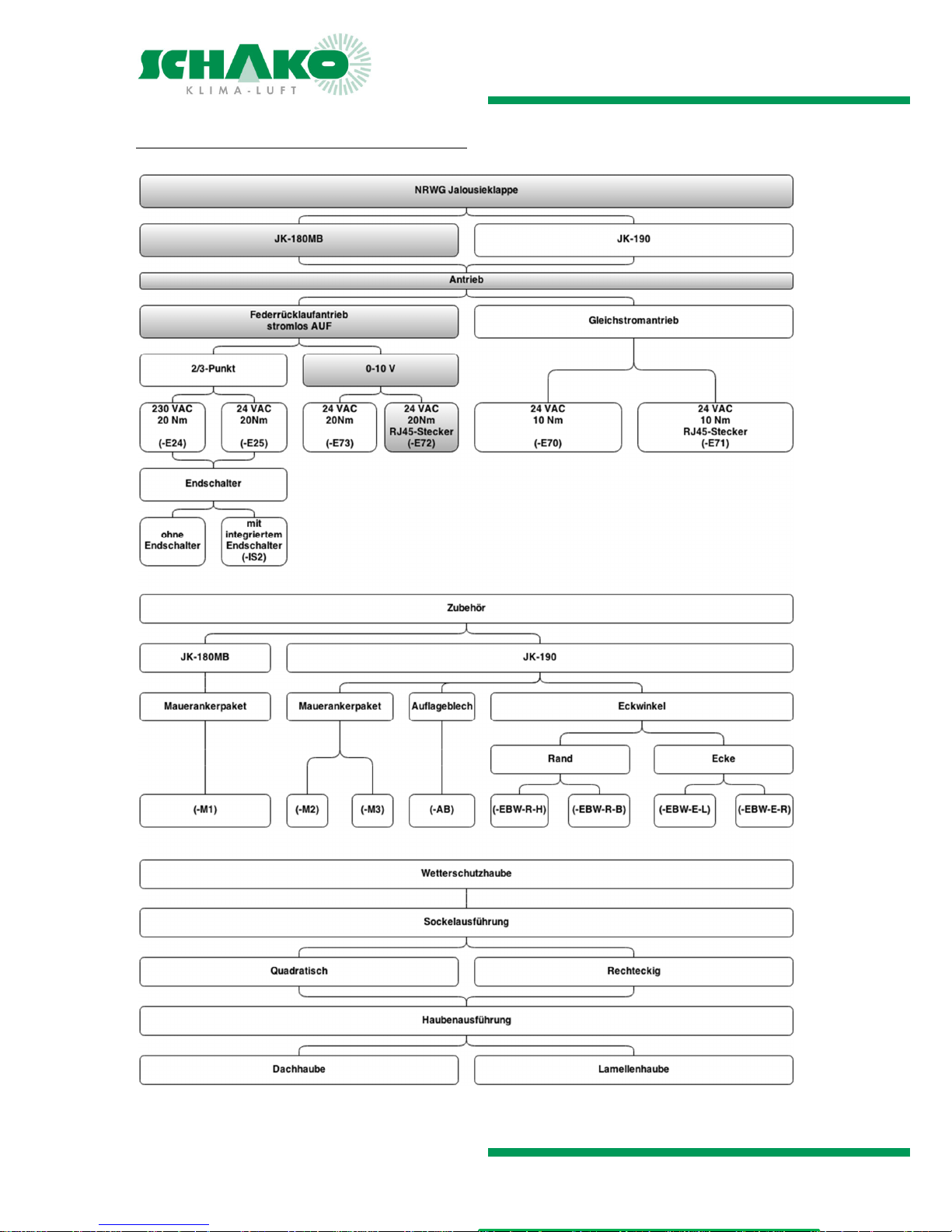
ORDER DETAILS
If no order details are given, the model highlighted in colour will be delivered!
Page 20
NRWG Multi-Leaf Damper Models JK-180MB / JK-190
Technical documentation
CE marking |
Construction subject to change
No return possible Version: 2016-08-02 | Document: 09/53 | Page 20
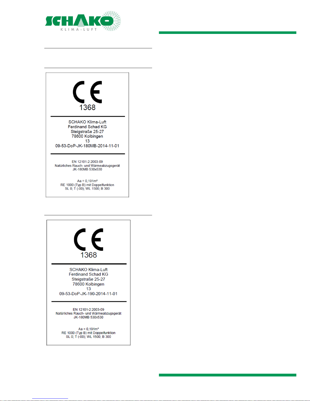
CE MARKING
JK-180MB
JK-190
Page 21
NRWG Multi-Leaf Damper Models JK-180MB / JK-190
Technical documentation
Prior to assembly and commissioning | Maintenance and function
Construction subject to change
No return possible Version: 2016-08-02 | Document: 09/53 | Page 21
PRIOR TO ASSEMBLY AND COMMISSIONING
Each SCHAKO product comes with instructions on [Safety / Transport /
Disposal] and [Installation / Commissioning / Maintenance]. For safety
reasons, they must be read and observed. Multi-leaf dampers may not
be lifted at the louvres and not be
used as "ladder".
At the gear wheels and cutting edges, there is a risk of injury.
Mounting to the wall/ceiling must take place without deformation, without tensions, level and without angular errors.
The multi-leaf dampers must be installed in open position.
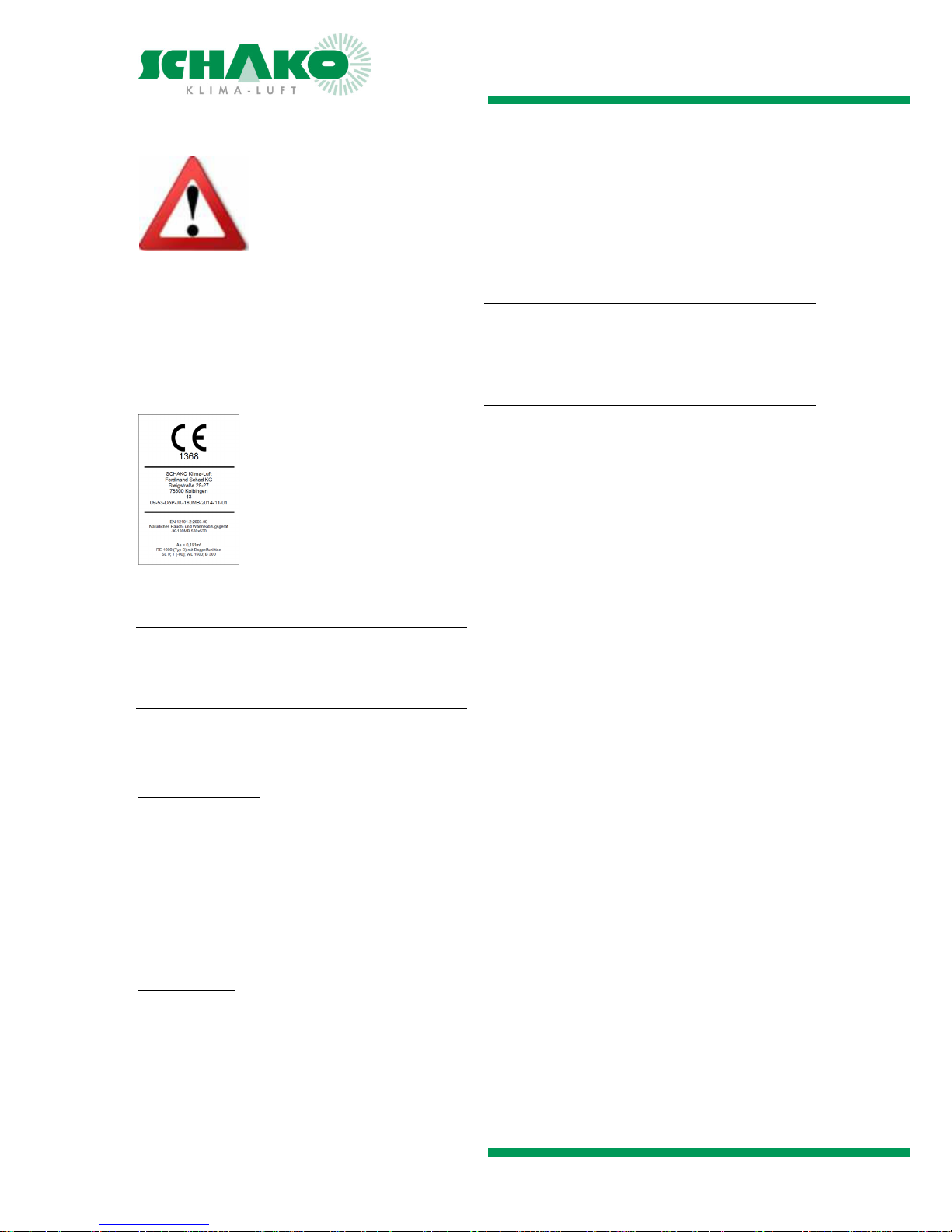
MARKING
The product is labelled with the marking
shown opposite in accordance with the
Construction Products Regulation
(BauPVO) EU 305/2011.
The CE marking is located on the actuator side.
The operating safety of the devices is
only guaranteed when used in accord-
ance with their designated use.
DISPOSAL
After its final decommissioning, the multi-leaf damper must
be properly disposed of by a competent body.
TESTS AND STANDARDS
The NRWG multi-leaf damper has been certified by the Notified Body according to EN 12101-2 and additionally inspected in accordance with the following regulations:
Completed inspections
VDI 6022, Sheet 1: Hygienic requirements of ventilation
and air-conditioning systems
VDI 6022, Sheet 2: Hygienic requirements of ventilation
and air-conditioning systems - Measurement methods and
investigations during hygienic controls and hygienic inspections
DIN EN 1751: Ventilation of buildings – units of the air dis-
tribution system:
--- Housing leakage class C
--- Leakage with closed damper leaf class 3
Applied standards
EN 12101-2
DIN EN 1751
VDI 6022
EMC 2004/108/EC
Low voltage 2006/95/EC
Measurement, requirements and installation of natural
smoke removal systems (NRA) according to DIN 18232-2
MAINTENANCE AND FUNCTION
It is recommended performing regular maintenance and
functional checks of the entire smoke and heat exhaust ventilation system. Maintenance must be performed in accordance with legal regulations (at yearly intervals). Accordingly,
functional checks should also be carried out at regular intervals. Maintenance must always be performed by personnel
trained for this purpose.
Note
Impure and humid air may impair permanent operational
safety. If maintenance agreements are concluded for RWA
systems, the functional checks of the NRWG should be included in these maintenance agreements.
VERIFICATION
Visual inspection
Check NRWGs for damage and contamination
Carry out necessary cleaning work
When cleaning, please note that cleaning agents may
damage seals.
Functional check
Check actuator for perfect functioning and condition (ob-
serve manufacturer's operating instructions)
Check actuators and fastening for tight fit
Check entire opening and closing process of the NRWG:
- Spring return
- DC motor
- Alternatively: Actuate a ventilation switch (if avail-
able)
- It may only be actuated via the drive shaft provid-
ed for this purpose. Actuation by rotating louvre is
prohibited.
 Loading...