

Page 1
NSG 438
601-241D
User Manual
NSG 438
ESD Simulator
Page 2

Page 3

NSG 438
Contents
1 Explanation of the symbols used in this manual.........................1
2 Safety.............................................................................................2
3 Introduction...................................................................................4
3.1. Electrostatic discharge (ESD)..........................................................4
3.2. Simulation.......................................................................................4
3.3. Effects on the EUT...........................................................................7
4 The NSG 438 system.....................................................................8
4.1. The generator..................................................................................9
4.1.1. Function modules............................................................................9
4.1.2. Block diagram................................................................................10
4.1.3. Operating elements.......................................................................12
4.2. System components......................................................................14
4.2.1. Battery charger / power supply unit................................................14
4.2.2. Options..........................................................................................15
4.2.3. Discharge networks.......................................................................15
4.2.4. Remote triggering..........................................................................16
4.2.5. Interlock.........................................................................................18
4.2.6. Measurement adapters..................................................................22
5 Commissioning............................................................................23
5.1. Function test..................................................................................23
6 Operation.....................................................................................25
6.1. Switching on..................................................................................25
6.2. Battery monitoring..........................................................................26
Page 4

NSG 438
6.3. Operation and settings...................................................................27
6.3.1. Display mode.................................................................................28
6.3.2. Voltage..........................................................................................29
6.3.3. Polarity..........................................................................................30
6.3.4. Counter.........................................................................................30
6.3.5. Repetition......................................................................................31
6.3.6. Settings.........................................................................................32
6.3.7. Language......................................................................................32
6.3.8. Device info....................................................................................32
6.3.9. Discharge......................................................................................32
6.3.10. Threshold......................................................................................33
6.3.11. ISO-Selftest...................................................................................34
6.3.12. Level.............................................................................................35
6.3.13. Program........................................................................................35
6.3.14. Trigger button................................................................................36
6.3.15. Continuous operation.....................................................................36
7 Test procedures...........................................................................37
7.1. Standard-compliant procedures.....................................................37
7.2. Other situations.............................................................................32
8 Verification of the pulse data......................................................39
9 Typical pulse data........................................................................40
10 Maintenance.................................................................................41
10.1. Calibration.....................................................................................41
10.2. Exchanging the R-C network.........................................................42
10.2.1. Reduction of pulse repetition rate at increased capacity.................43
Page 5

NSG 438
10.3. Repairs..........................................................................................43
10.4. NSG 438 System error messages ................................................. 44
10.5. Disposal........................................................................................ 45
11 Technical specifications..............................................................46
12 ESD standards.............................................................................48
13 Warranty.......................................................................................49
14 Ordering information...................................................................50
15 Addresses....................................................................................51
Manufacturer
Schaffner EMV AG
Nordstrasse 11, 4542 Luterbach/Switzerland
www.schaffner.com
Page 6

Page 7
NSG 438
1
1 Explanation of the symbols used in this manual
Please take note of the following explanations of the symbols used in order
to achieve the optimum benefit from this manual and to ensure safety
during operation of the equipment.
The following symbol draws your attention to a circumstance where nonobservation of the warning could lead to inconvenience or impairment in
the performance.
Example:
This connection must not be confused with the main
power input
The following symbol draws your attention to a circumstance where nonobservation of the warning could lead to component damage or danger to
the operating personnel.
Example:
Never connect or disconnect the pistol while system is
performing a test
Page 8
NSG 438
2
2 Safety
This item of equipment, together with its accessories,
works at high voltages of up to 30kV. Any careless
handling or non-observance of the operating
instructions can have dangerous consequences.
The NSG 438 generator is not a toy! It is a professional tool and belongs
only in the hands of specialists and appropriately trained personnel.
When powered by its own batteries the generator can be active even
without any power cable being connected.
The instrument must not be switched on unless a correctly connected
earth or earth cable (pulse current return path) is in place. The original
earth cable supplied with the instrument is to be used. Any replacement
cables must be fabricated in such a way that they cannot be accidentally
connected to a mains outlet socket. Do not touch the test finger! There is a
danger of an unpleasant electric shock if the instrument is switched on
(LC-display active).
Only trained personnel may operate the instrument.
Personnel fitted with a heart-pacemaker must not operate
the instrument nor approach the test rig while it is in
operation.
These operating instructions form an integral part of the instrument and
must be available to the operating personnel at all times.
The instrument must not be used for any purpose other than testing the
ESD immunity of electronic equipment.
The construction of the generator is not designed for use in an explosive
environment.
Page 9
NSG 438
3
Each electrostatic discharge produces powerful
electromagnetic interference.
Nearby electronic equipment can be seriously disrupted
unless the appropriate counter-measures are taken.
Perform ESD tests preferably in a shielded room.
If a network needs to be exchanged, the test has to be
stopped first, followed by a waiting time of at least 5s
to ensure the voltage being internally discharged.
The rechargeable batteries in the base station must not be short-circuited
under any circumstances. They must only be recharged with the original
charging unit supplied with the generator. Should they have to be
replaced, kindly observe the relevant recommendations for their correct
disposal.
The instrument must not be opened. Repairs, maintenance work and
internal adjustments are only to be carried out by a qualified service
engineer. Use the instrument only in dry surroundings. Any condensation
that occurs must be allowed to evaporate before putting the generator into
operation. Long periods of exposure to sunlight and excessive warming by
external energy sources are to be avoided.
Do not continue to use the instrument should any mechanical damage
occur. The instrument's housing and the cable have both an insulating and
a screening function, which can only be assured while the housing is
intact. Return a damaged generator to a Schaffner service centre
immediately for repair.
Schaffner EMV AG Luterbach, Switzerland and the associated sales
organization accept no responsibility for personal or material damage nor
for any consequential damage that results from irresponsible operation of
this instrument.
Page 10

NSG 438
4
3 Introduction
Under appropriate ambient conditions, both material objects and even the
human body itself can become charged with electrical energy. This effect
is due to "electrostatics", a phenomenon that has been known since the
earliest times. Thales von Milet (600 BC) noticed how amber attracted very
light particles when it was rubbed. Touching a charged item against a
conductive object leads to a charge equalization through a spark
discharge, which produces a brief but powerful electro-magnetic field.
3.1. Electrostatic discharge (ESD*)
This effect can be explained as follows: Two insulating substances with
differing dielectric constants become charged when rubbed together, i.e.
one material gives electrons to the other one. This effect is known as
electrostatic charging. The same can happen to a person. When
somebody walks around in a dry atmosphere on carpet while wearing
shoes with good insulating properties, a charge of several thousand volts
can be built up. If, now, that person comes close to a conductive surface,
the charge that he or she is carrying flows away through a hefty spark
discharge.
The high equalizing current that flows, and the associated large
electromagnetic field that hence results, can cause electronic devices
(computers, terminals, process controllers, vehicle electronics, solid state
devices, credit or memory cards, etc.) to malfunction or even be destroyed.
* ESD = electrostatic discharge
3.2. Simulation
A systematic investigation of electronic equipment and installations to
determine their electromagnetic compatibility (EMC) is, today, a necessity
if one is not prepared to suffer the economic disadvantages that could
otherwise ensue. As a logical consequence, appropriate testing is now a
legal requirement for the sale of electronic products within the EU.
The ESD-test plays an important role in the range of interference
sensitivity tests. It simulates frequently occurring effects and guides the
development engineer to any weak spots in an instrument or item of
equipment through a combination of high voltage and high frequency
properties.
Page 11

NSG 438
5
A simulation device must be constructed such that it reproduces practical
conditions realistically. Furthermore, the results obtained (interference
sensitivity threshold) must be reproducible.
The interference immunity of an instrument is not only dependent on its
construction, it is also largely dependent on the quality or the consistency
of the mass production techniques used. Knowing this has led to the
demand for individual testing or at least random sample testing.
Further weak spots, which could affect the overall interference immunity,
can arise through the assembly of instruments into complete systems
because of the installation method used, the cabling and the earthing. An
ESD check on systems is therefore also prescribed. Such tests provide
valuable information about the immunity of the system to effects that occur
only sporadically under operating conditions and hence represent difficult
to detect sources of disruption.
Page 12

NSG 438
6
The ESD generator NSG 438 fulfils the requirements of numerous
applications in an ideal manner, thus:
Ergonomic shape For non-tiring use
Operation Operating elements and display always in
view of the user. Constant check on the test
values.
Battery-powered Independence from a mains power feed.
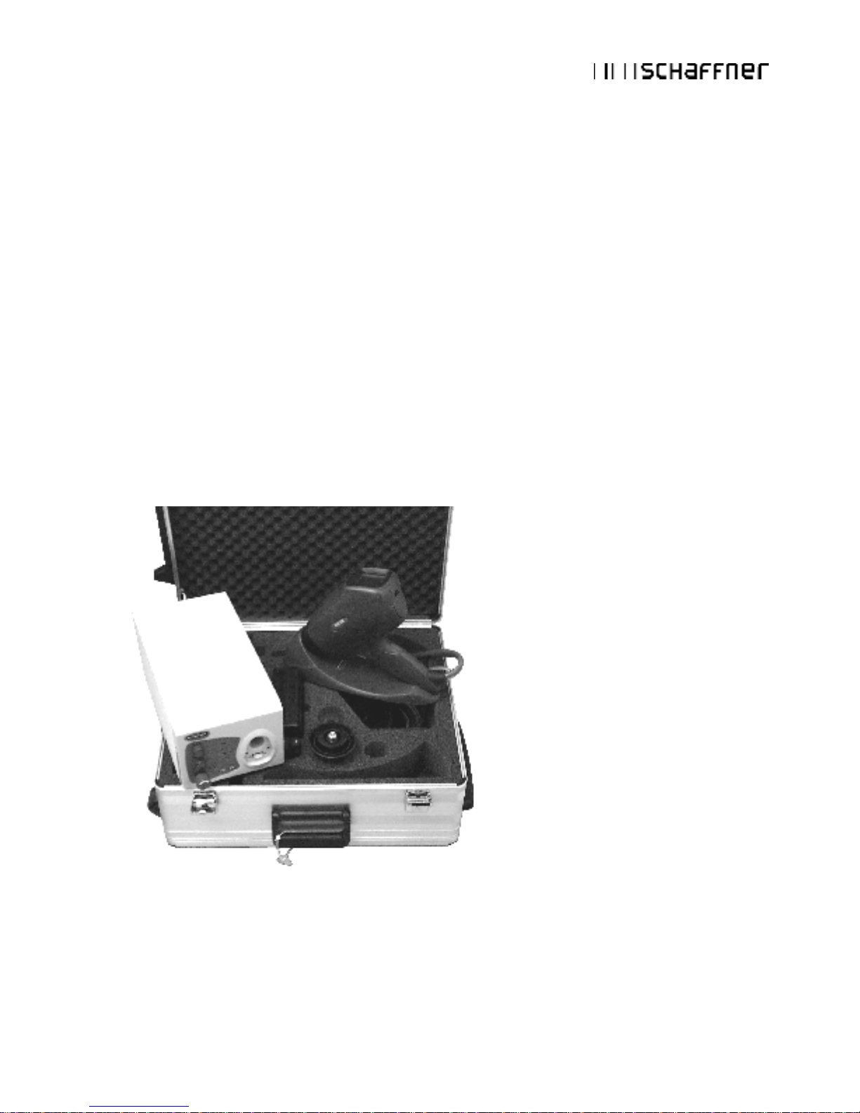
Carrying case Generator and its accessories can be readily
packed and conveniently transported.
Microprocessor-control All the functions are "on-board", including a
pre-settable counter, pre-programmed test
values, discharge voltage measurement, etc.
Precision The test parameters are maintained precisely
for reliably reproducible tests.
Flexibility The specifications prescribed in the standards
are more than fulfilled in every respect. The
instrument also offers many additional handy
features.
Safety The high voltage generator is automatically
deactivated if the instrument remains unused
for a period of time.
Long-term operation Automatic long-term operation for stationary
applications with the generator mounted on a
tripod.
Application field Development optimization, type-approval,
EMC certification, batch testing (individually),
testing of fully installed systems.
Page 13

NSG 438
7
3.3. Effects on the EUT
The most significant interference components of an electrostatic discharge are
of a high frequency nature. The interference paths and effects have to be
assessed in the range from about 30MHz to multi-GHz.
The extremely rapid rise time of a discharge affects an object under test
mostly through:
§ magnetic HF-coupling between electrical conductors in the
electronics and the discharge current path.
§ electrical coupling between the discharge current and signal
lines. A discharge current to the EUT flows proportionally through
all the associated conductors (earth, mains, data lines,
screening, etc.) according to their relative impedance.
Malfunctions in insufficiently immune electronic equipment and systems
make themselves apparent through:
§ program crashes
§ blocking of command sequences
§ incorrect commands, statuses or data being further processed
§ partial system resets (e.g. only in peripheral modules, which lead
to errors that the system does not recognize)
§ disturbance or destruction of interface modules
§ destruction of insufficiently protected MOS components.
ESD (electrostatic discharge) testing usually shows up all the weak spots
in the HF-range of a piece of equipment simultaneously. The uses to which
the NSG 438 ESD simulator can be put hence go way beyond those called
for in standard-conform applications.
This instrument provides the engineer with a means to detect sources of
error caused by unsuitable earthing, poor ground connections, insulation
problems, etc.
The generator also serves as a reliable aid for localizing hidden wiring
faults during acceptance trials on installations.
Use can also be made of the instrument as an insulation tester to
determine the breakdown voltage of switches, relay contacts, insulators,
etc.
Page 14

NSG 438
8
4 The NSG 438 system
By using the latest materials, construction methods and manufacturing
techniques for the robust housing shell, together with highly insulated
modules, the newest high voltage technology, the touch-sensitive
operating panel and a control unit built using the SMD-technique, it has
been possible to integrate all the functions that a comprehensive simulator
system should offer into one compact instrument.
Professional industrial designers have ensured an optimized ergonomic
concept. The instrument, with its well-balanced handgrip, sits comfortably
in the user's hand and guarantees non-tiring operation. Both the operating
elements and the display window remain in view of the user while work is
in progress.
The NSG 438 offers optimal freedom of movement around the work-place
and is an ideal test instrument not just for the development engineer but
also for quality control purposes, system tests and for investigations in the
field.
As supplied in the basic set, the system is equipped with a 150pF / 330Ω
discharge network for the IEC / EN 61000-4-2 (2001) standard.
The discharge voltage of up to 30kV for both Air-Discharges and ContactDischarges ensure a comfortable test margin over and above the levels
called for in the standards.
The instrument is well equipped to cope with other (and future) standards.
The accessories include various networks and test fingers that can be
attached by the user himself.
The basic set contains everything necessary for general use. A rich
assortment of accessories for special tasks is available such as a remote
triggering unit, further discharge networks, an ergonomically shaped
carrying case, a tripod adapter, test fingers, etc.
Page 15
NSG 438
9
4.1. The generator
The NSG 438 generator is modularly constructed from a number of
discrete function units.
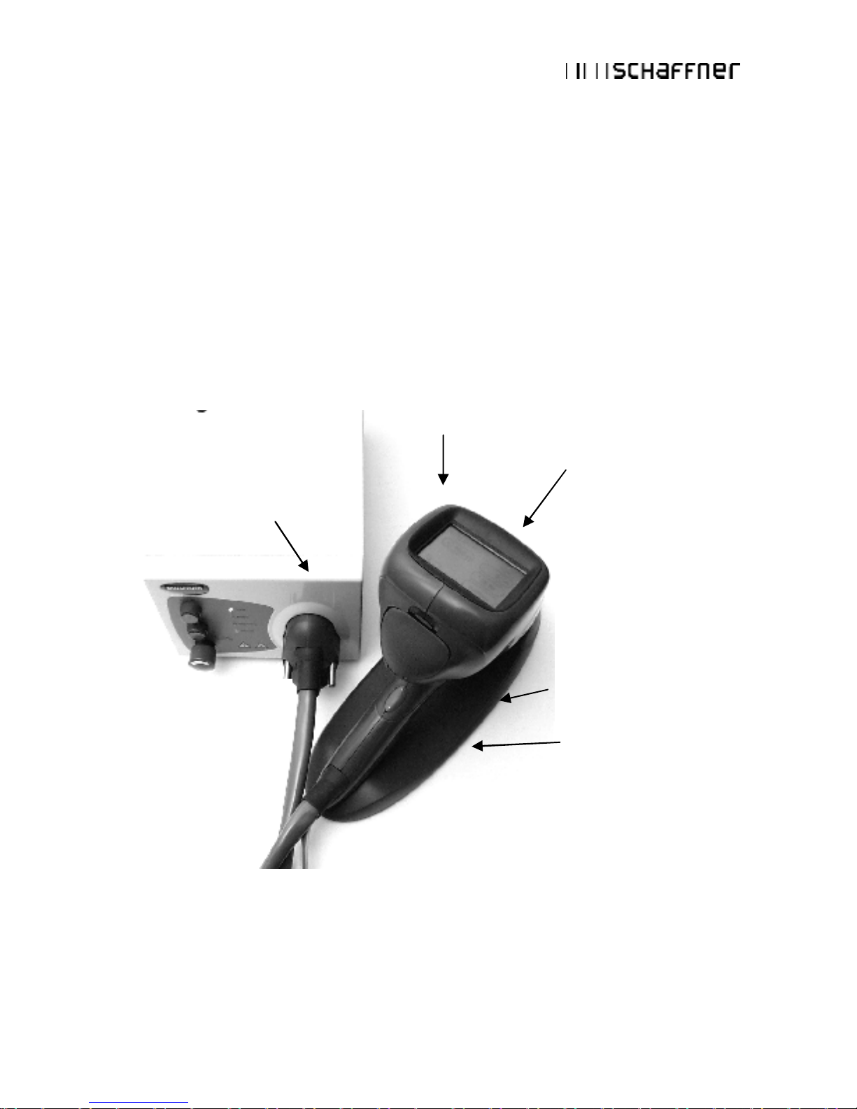
4.1.1. Function modules
The base station contains the battery supply, the high voltage generator
and regulator as well as several safety features.
The pistol houses the interchangeable pulse network, high voltage relay,
the exchangeable test finger, measuring electronics and the touchsensitive input / display panel.
Pistol
Display and
touch-panel
Network
(exchangeable)
Pistol stand
On/Off button and
emergency off switch
Base station
Page 16
NSG 438
10
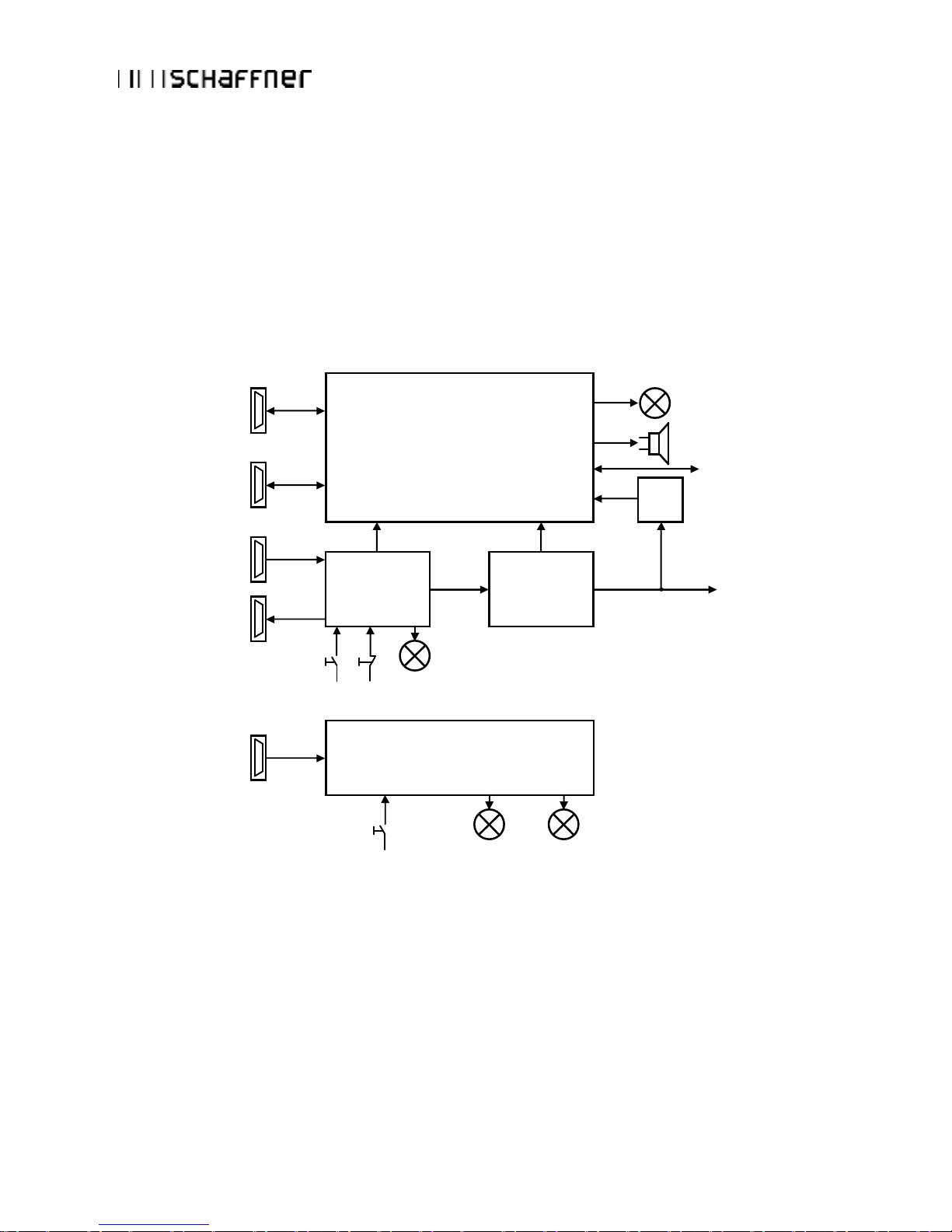
4.1.2. Block diagram
The various function units are shown in the block diagram:
Block diagram of the base station:
µP Control Unit
Buzzer
High Voltage
active
Communication to
Discharge Pistol
Meas.
Circuit
High Voltage to
Discharge Pistol
High Voltage
Generator
+ / -
Interlock Unit
Communication to
the PC (Opto Link)
External Trigger
EUT Fail
Interlock IN
Interlock OUT
24 VDC
PSU and Battery
Power On Power Batt. Status
Interlock
Interlock
Reset
Page 17
NSG 438
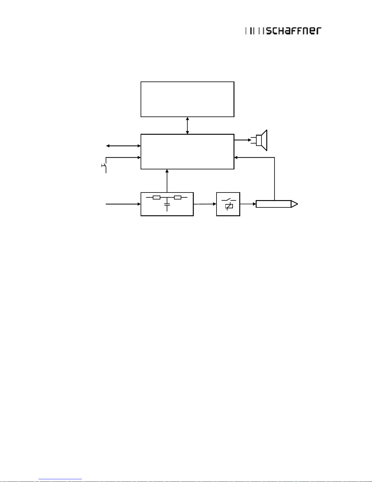
11
Block diagram of the pistol:
The microprocessor controls and monitors all the generator functions:
§ Touch-panel entries are checked for plausibility. Unacceptable
entries are rejected and an acoustic warning notifies the user of
the error.
§ Values entered are clearly shown on the large display screen.
Further information shows the operating status and the counter
settings.
§ The battery charge state is continuously monitored. The display
warns if there is a tendency towards low voltage. The
instrument's functions are inhibited once the battery voltage is
insufficient to guarantee the pulse parameters.
§ High voltage generation is dynamically controlled by the
processor. Varying load conditions, supply voltages, etc. can
thus be taken into account and have no effect on the pulse
parameters.
High Voltage
Manual Trigger
Communication to
the Base Station
Discharge Network
Display with
Touch - Panel
µP Control Unit
High Voltage
Relay
Test Finger
Buzzer
Tip Ident.
Network Ident.
Page 18

NSG 438
12
§ The instrument switches itself off automatically if it is not used for
a while. The pulse parameters and operating mode remain
stored and ready for re-use.
§ The charge voltage to the network is kept constant as long as the
trigger is active. The high voltage is discharged internally when
the trigger is reset.
§ If no discharge occurs when set for an Air-Discharge and the
trigger is active, the processor waits for about 15s then autonomously resets the trigger and discharges the network internally
with simultaneous acoustic warning.
§ A measurement facility detects an actual valid discharge and
shows it on the display.
§ Pulse triggering is monitored. Once an arc has occurred the
network is discharged internally so that no further arcing is
possible.
4.1.3. Operating elements
Apart from the trigger button itself (pulse triggering), all the operating
elements, test-relevant setting and user information are presented on the
touch-sensitive display panel facing the operator.
The NSG 438 is switched on and off with the main power switch. The
significance of the elements in the display field can be seen in the
following picture. Further information can be found in section “Operation”.
Page 19

NSG 438
13
All operations are performed via the touch-panel.
The following display is shown on the panel when the pistol is switched on.
The function of the trigger button on the handgrip depends on the
operating mode currently selected:
§ As a pulse button in single discharge mode (1 pulse each time it
is pressed).
§ As an on/off switch in repetitive mode (discharges while button is
pressed).
§ As a pausing on/off switch in repetitive mode with the preset
counter in operation (start the discharges by pressing the
button/stop the discharges by pressing the button again).
The remote control facility replicates the action of the trigger button by
means of appropriate control signals.
Page 20

NSG 438
14
4.2. System components
The basic set is packaged in a practical carrying case and comprises:
§ Carrying case
§ ESD generator NSG 438 consisting of a pistol and a base station
with a battery power supply
§ Discharge network 150pF / 330Ω
IEC / EN 61000-4-2 (2001)
§ 1 test finger each for air and contact discharges
§ Battery charger / mains power pack
§ Pistol stand
§ Operating instructions
This set contains all the items necessary under normal conditions to
conduct tests conforming to the
IEC / EN 61000-4-2 (2001) standard.
4.2.1. Battery charger / power supply unit
Power to the instrument is provided through a universal mains unit suitable
for input voltages between 80 and 240Vac. This same unit also serves as
a charger for the integral battery pack.
Charging of the battery takes about three hours. At this point a timer
switches the charger to a reduced charging current and the indicator lamp
changes from red to green.
The battery will also charge up when the instrument is switched off.
A full battery charge will suffice for several days of normal test operation.
Battery life expectancy:
§ Ambient temperatures over 50°C can lead to degradation of the
battery. If treated carefully, more than 300 charge / discharge
cycles can be expected without a noticeable reduction in
capacity.
§ The charger and battery-pack form a matched entity. The battery
must not be charged from any other unit and the charger is to be
used exclusively for the intended purpose.
Page 21

NSG 438
15
Operating advice:
§ Use the equipment only in dry surroundings.
§ Recharge the battery about every 6 months even if the
instrument is not being used.
4.2.2. Options
A range of additional accessories is available for special applications and
for testing to alternative standards:
§ Discharge networks and test fingers for other standards
§ Fast rise time tip
§ Coaxial measurement adapter type MD 101 or MD 102
§ Carry-bag for base unit
§ Tripod adapter
§ Opto link to a PC
§ H-field adapter
§ Flexible test tips
§ Discharge remoter
4.2.3. Discharge networks
The basic set contains a discharge network and test fingers for conducting
tests that conform to IEC / EN 61000-4-2 (2001) alternative networks can
be installed for testing in accordance with other standards.
Several networks are given in the order-list. The C and R values of the
discharge network can also be specified for other applications. Networks
conforming to other standards can be built upon request. The
specifications of the standard must be fully defined.
Exchanging the discharge network is described in section “Exchanging the
R-C network”.
Page 22

NSG 438
16
4.2.4. Remote triggering
A remote triggering unit can be connected to operate the NSG 438 inside a
Faraday cage with external pulse triggering or for test pulse triggering in
synchronism with other conditions.
Connector pin-out:
Connector J3: Pin assignment
Pin Signal name Description
1 EXT_TRIGGER External trigger input
2 NC --3 NC --4 EUT_FAIL EUT failure input
5 GND Earth
6 NC --7 NC --8 NC --9 NC ---
PC Interface
Ext. Trigger
EUT Fail
Interlock IN
Interlock OUT
DC IN
J3
Page 23

NSG 438
17
Ext. Trigger:
The following circuit is built in behind the connector:
1k
120k
Ext. Trigger
10nF
Vcc
EXT_TRIGGER
(Port A.6)
EUT failure Input:
The same circuit is used for the EUT failure input:
1k
120k
EUT fail
10nF
Vcc
EUT_FAIL
(port A.7)
Page 24

NSG 438
18
4.2.5. Interlock
The NSG 438 has an integrated interlock system in keeping with standard
practice for high voltage test equipment.
This system has the following functions:
Inputs:
1. Input for external monitoring purposes of, for example, special
coupling networks and access control.
2. Internal emergency off button opens the interlock.
Outputs:
1. Operating mode: the NSG 438 can generate no high voltage as
long as the interlock is not closed. High voltage generation is
prevented if the interlock is opened during a test procedure.
2. Warning lamps: when the interlock is closed the green lamp is
switched off and the red lamp is illuminated.
3. Interlock output for other system devices.
The interlock system is common to all Schaffner instruments and hence
several devices can be connected together.
The instrument is equipped with two 15-way connectors for interlock input
and output. The interlock loop must always be correctly terminated at both
ends. In achieving this, the interlock wiring must connect all the safety
contacts together.
When using original Schaffner accessories this is achieved automatically
by using 15-way standard cables wired 1:1 to link the interlock connectors.
An arbitrary number of instruments or accessories can be incorporated in
this safety concept.
The high voltage supply can only be activated if the safety requirements in
all the associated devices are fulfilled (emergency off buttons released,
safety contacts closed).
Page 25

NSG 438
19
To conform with VDE 0104, the control of the warning lamps must make
use of the interlock feature. The instruments can be switched on and the
red lamp lights up as soon as the interlock circuit is complete.
The pair of terminating connectors supplied must be utilized in the case of
not making use of external interlock contacts.
Signal specifications: Voltage 48Vdc max.
Current 20mA min., 1A max.
Connector: Socket, D-sub. 15-pin
Max. permissible
cable length: 3m each, screened cable
(correct operation guaranteed up to 10m)
Operation effected via potential-free switch contacts.
All signals are active LOW, i.e. switched to GND.
The pin-out of the interlock input and output connector is identical. All the
pins are connected together. The connection to pin 3 is made internally
through the emergency off button. This link is broken when the internal
interlock is activated.
Page 26

NSG 438
20
Pin-No. Function
1 Earth (GND), 0V
2 NC, linked through to the other interlock socket
3 Interlock input/output (connected inside the instrument)
4 NC, linked through to the other interlock socket
5 Interlock status (trigger the interlock function in the instrument,
internal relay from +12 to +48V)
6 NC, linked through to the other interlock socket
7 NC, linked through to the other interlock socket
8 NC, linked through to the other interlock socket
9 Switches warning lamps and peripherals on (active, provided that
NSG 438 is switched from Standby to on).
10 NC, linked through to the other interlock socket
11 NC, linked through to the other interlock socket
12 NC, linked through to the other interlock socket
13 NC, linked through to the other interlock socket
14 NC, linked through to the other interlock socket
15 NC, linked through to the other interlock socket
Shell Screening
NSG 438
Wiring diagram for the interlock system:
S: External safety switch (e.g. test enclosure hood, door contact, panic
button, etc...)
Several interlock inputs of this type may be connected in parallel.
Page 27

NSG 438
21
The contacts should be connected in series if numerous access barriers
are necessary. Either one open contact or a voltage of more than 1.5V at
the input is sufficient to disable the generator.
Interlock Relay
EUT
Power Relay
Page 28

NSG 438
22
4.2.6. Measurement adapters
The measurement adapter type MD 101 as per IEC / EN 61000-4-2 (2001)
serves to verify pulse amplitudes and pulse shapes. It is designed for
mounting in the side wall of a Faraday cage in which an oscilloscope has
been installed. This measurement adapter has the flat impedance curve to
well over 1GHz that is necessary for the purpose.
Use of this adapter is only worthwhile in conjunction with a test rig that is
laid out in strict conformity with the relevant standard (see section
“Verification of pulse data”).
MD 102 (“Pommerenke” target) is a more advanced coaxial measuring
target with flat response characteristics up to the multi-GHz range. It may
be used instead of MD 101.
MD 102
Page 29

NSG 438
23
5 Commissioning
Immediately upon receipt, check the instrument and the accessories for
completeness and look for any transport damage. Damage incurred in
transit must be reported to the transportation undertaking without delay.
Before putting the instrument into operation:
§ Study the manual
§ Take the necessary safety precautions
§ Charge the battery (see section “Battery charger”)
§ Plug the interlock terminators into the base station
§ Connect the earth cable correctly (The NSG 438 must never be
switched on without a solid earth connection being made).
§ Allow the instrument to dry out if any condensation has occurred
5.1. Function test
Switch the generator on with the on/off switch.
The instrument performs audible switching operations for a few moments
as it runs through a self-test and calibration procedure.
The instrument is ready for use once the self-test routines have been
completed.
The default display looks like this:
High voltage generation is activated by pushing the trigger button and
keeping it depressed.
Page 30

NSG 438
24
By bringing the test finger close to the earthing point an arc discharge occurs
which is acknowledged acoustically and the display shows the preset
discharge voltage in a frame. (This applies under the following conditions:
Air-Discharge, single-pulse, pre-select counter off).
Page 31

NSG 438
25
6 Operation
This section of the manual provides a guide through the numerous
operating possibilities of the NSG 438.
The operation, which is strictly logical and hierarchically arranged, is
therefore easy to remember. The display shows unmistakable information
about the parameters that have been set and the operating status of the
generator. Equally, the instrument refuses to accept any invalid entries.
It is recommended to carry out the examples directly on the instrument
(not forgetting to connect the earth cable!).
6.1. Switching on
Ensure the interlock terminators are plugged into the rear of the base
station or otherwise the interlock loop is complete.
Plug the pistol HV connector into the base station and tighten the screws.
Ascertain that the base station as well as the earth cable
for the pulse return path are solidly connected to the
fixed installation’s earth point.
There is a danger of electric shock if this is neglected!
Ensure the Emergency Power Off button is pulled out.
Press the Power On button. The green Power LED will light up.
Press the Interlock Reset button. The red Interlock LED will extinguish
and the red High Voltage LED blinks while the pistol runs its self-test and
calibration routine.
The instrument is ready for use immediately after self-test and calibration
procedures have been completed. High voltage generation is activated by
pressing and holding the trigger button. The active high voltage state is
indicated on the base station by a blinking red LED.
Page 32

NSG 438
26
Should a parameter need changing the operator has only to press on the
relevant field in order to call up the appropriate menu.
The value of discharge voltage is displayed following a successful air
discharge. A differentiation is made between this and the set value by the
display kV being inversed. If no valid discharge occurred, the display
shows a 0 value. The Threshold function (see section “Threshold”)
permits various settings for the sensitivity of the breakdown voltage
detector.
The effective discharge voltage depends on various factors such as the
distance to the discharge point, speed of approach, nature of the EUT, etc.
In the case of a contact discharge this measurement is not carried out
since only a discharge current can occur.
The instrument switches itself off automatically after 15 minutes of nonuse.
6.2. Battery monitoring
The battery charge state is monitored continuously. An insufficiently
charged or an empty battery is shown on the display.
Recharge the battery soon when this symbol is displayed.
Correct operation and valid pulse parameters are still assured.
The battery is more or less empty; its capacity is insufficient to
maintain all the instrument’s functions. An appropriate warning
message is shown on the screen and all the instrument’s
functions are inhibited.
Page 33

NSG 438
27
Remark
A full battery will provide sufficient power for several days of normal test
usage. The actual operating time depends, of course, to a large extent on
the conditions prevailing at the time.
The following figures have been obtained by way of reference:
§ Battery freshly charged
§ Contact-Discharge with 30kV
§ More than 20’000 discharges can be generated
6.3. Operation and settings
The operation of the instrument and all settings are carried out by way of
the touch-panel starting from the menu TEST. Generally, the following
applies:
§ Frames symbolize push buttons. Touching these sensitive areas
causes a reaction, usually branching into another menu.
§ Values and indications that are not in frames are for information
only. Pressing the ‘Return‘ button always takes you up one
menu level higher.
§ A virtual rotary control wheel appears in parameter setting
menus. Sensitivity and lent weight are matched to the parameter
to be adjusted. Stroking the ‘wheel‘ with the finger-tip causes it to
‘rotate‘ and changes the selected parameter. When you wish to
alter the setting for either the voltage or the pre-select counter
you can let the wheel spinning at different speeds. Activating it
energetically will cause it – just like a mechanical one – to run on
and thereby set the particular parameter higher or lower
correspondingly more quickly.
TEST
2.0 kV
IEC 1
R: 300 C: 150
1 Hz
Settings
45
local
Page 34

NSG 438
28
§ Only stroke the portion of the wheel displayed otherwise you
might prevent it from running on freely.
§ There are pressure-sensitive areas (invisible) at the top and
bottom edge of the display associated with the wheel with which
you can adjust the relevant parameter by +1 or –1. Try it out.
Play with it and you will quickly get the feel of it and how it best
functions.
§ R/C value shown on main screen for more convenient direct
reading.
6.3.1. Display mode
An alternative method to the virtual thumb-wheel to control the instrument
has been incorporated.
Via the button "Settings" and "Display mode" a keyboard and up/down
buttons can be selected instead of the thumb-wheel.
26.3 kV
Prog. 2
Rep 20 Hz
Settings
2345
RUN MENU
local
Keyboard
Display mode
Display mode
Settings
Page 35

NSG 438
29
Numerical values (voltage, preset counter, random repetition times) can be
entered just the same as with a pocket calculator.
Selection functions (such as language, type of discharge, program
number, etc.) are handled by up/down buttons to scroll through the
settings.
This extended operating function is included in NSG 438 products from
serial number 339 (August 2004) upwards.
6.3.2. Voltage
Touching the voltage indication brings you to the sub-menu for adjusting
the discharge voltage. Set the required value with the wheel and press
return.
26.3 kV
Voltage
1
3
2
4
6
5
7
9
8
.
C 0
Single
Repetition
Page 36

NSG 438
30
6.3.3. Polarity
Touching the polarity indication brings you into the relevant sub-menu.
Choose between + or – with the wheel. If the pre-select counter function is
active there is the further option of choosing alternating +/- polarity.
6.3.4. Counter
Use the counter button to branch into the corresponding menu. Choose
the counter mode: Preset counter ON/OFF. In the ON state the counter
content can be set by means of the wheel. When the generator is in
operation the preset counter counts down until it reaches 0, which then
terminates the selected test sequence.
Note: - - - - means continuous operation without any preset counter
function. Pressing the trigger button starts the generator operating; a
second press on the same button stops the operation.
Reset counter sets the counter content to 0 or it reloads the preset counter
with the previously selected value.
Page 37

NSG 438
31
6.3.5. Repetition
The Repetition button takes you into the menu to select either single
pulses or a repetition rate from 0.5 to 25Hz in air discharge, or from 0.5 to
20Hz in contact discharge mode.
Two further repetition modes are available that trigger pulses with a
statistical distribution over a specified period:
Random P: 1 – 9999 pulses are triggered with a statistically
distributed repetition rate ranging from a minimum of
> 20ms to a maximum repetition rate of < 2000ms.
Random T: Pulses are triggered during a period of 1 – 9999 seconds
with a statistically distributed repetition rate ranging from
a minimum of > 20ms to a maximum repetition rate of
< 2000ms.
Free Adjust: For some specific product standards, the pre-stored
repetition times provided in Hz may not match all needs.
It allows entering values between 0.04s up to 300.00s in
0.01s steps.
Repetition
Free adj.
Free adjust
1
3
2
4 6
5
7
9
8
.
C 0
Rep. time 4.8
Page 38

NSG 438
32
The “Free Adjust” operating function is included in NSG 438 products from
serial number 521 (March 2006) upwards.
6.3.6. Settings
This branches into a range of sub-menus, thus:
6.3.7. Language
Touch the button and choose the language you wish to use with the wheel.
Note: Language looks like this in Japanese:
6.3.8. Device info
Gives information separately for the pistol and the base station regarding
the version of the equipment and its software.
6.3.9. Discharge
Use the wheel to select either Air-Discharge:
or Contact-Discharge:
The RC values for the relevant network are also shown.
The corresponding value is automatically loaded upon switching between
Air/Contact-Discharge when standard voltage values are selected.
The appropriate type of test finger must, of course, be mounted to suit the
type of discharge:
Air-Discharge = ball-shaped test finger
Contact-Discharge = sharp point test finger
An appropriate error message is displayed if the pistol detects wrong type
of finger has been mounted.
Page 39

NSG 438
33
6.3.10. Threshold
This function permits differing sensitivity levels to be set for the arcing
detector whereby a differentiation can be made between stray discharges
and a true discharge onto the EUT.
Normal: Arcing is detected and is indicated by the kV symbol on the
display blinking provided 20% (or more) of the charge voltage
is dissipated.
Low: Arcing is detected and is indicated by the kV symbol on the
display blinking provided 10% (or more) of the charge voltage
is dissipated.
High: Arcing is detected and is indicated by the kV symbol on the
display blinking provided 30% (or more) of the charge voltage
is dissipated.
Off: This position is made for EUTs with non-conductive surfaces
(housings).
This means in contact discharge mode, the arcing detection is disregarded
and the counter counts up/down as per settings in the repetition or counter
menu respectively.
In air discharges, this feature is available only in single mode. Pushing the
trigger once, the HV is activated and it can approach to the EUT until an
arcing happens or the EUT being touched. Then it has to push the trigger
a second time resulting in HV off and increasing/decreasing the counts,
depending on counter setting.
The “Off” operating function is included in NSG 438 products from serial
number 521 (March 2006) upwards.
Threshold
Off
Discharge detection
Page 40

NSG 438
34
6.3.11. ISO-Selftest
Just starting the ISO-Selftest gives a quick response of the proper
operation of the ESD generator. The screen reflects all required voltage
levels as well as the tolerances in table form, based on the ISO 10605
standard.
During the calibration procedure the HV module is strained up to 30kV. If
somehow the maximum voltage could not be reached or hold, the NSG
438 come out correctly with an HV error message. The calibration
procedure is diagnosing, to which voltage level the HV module will work
properly. This voltage value will be shown on screen while it will not be
possible to set a higher voltage value.
This extended operating function is included in NSG 438 products from
serial number 521 (March 2006) upwards.
Settings
ISO-Selftest
ISO
-
Selftest
kV 2
4 6 8 15 25
± 500V 10%
+
-
Page 41

NSG 438
35
6.3.12. Level
Provides the means to select the required, pre-programmed standard test
(e.g. IEC 61000-4-2, Level 4).
6.3.13. Program
Shows all the details of the currently selected settings in the “actual“ state.
These values can be saved in one of the eight memory places by pressing
store. Alternatively, a previously saved set of values can be recalled using
the wheel in the Actual program. Touching Return loads the selection
ready for execution.
min. 200V
^
RandT
Air
150pF/330Ω
45s 100ms 400ms
200
^
RandT
Air
150pF/330Ω
45s 100ms 400ms
200
^
RandT
Air
150pF/330Ω
45s 100ms 400ms
Page 42

NSG 438
36
6.3.14. Trigger button
This button functions in three ways:
In the Single discharge mode just one discharge is made each time the
button is pressed.
In the Repetitive mode pulses are generated at the pre-determined rate
for as long as the button is pressed.
In the Preset counter mode pulses start to be generated when the button
is pressed and continue until the button is pressed again or until the
counter decrements to zero, whichever comes first.
6.3.15. Continuous operation
Continuous operation can be established to produce a repetitive stream of
discharges, thus:
Set the preset counter to read - - - - in the counter menu. This enables
continuous operation without any intervention by the counter.
Pushing the trigger button starts the continuous operation; pressing it
again stops the operation.
§ Continuous operation should only be utilized in cases
of real necessity since every ESD radiates electromagnetic disturbance the effect of which on the
environment must be taken into consideration.
§ The test area should be made out of bounds for
unauthorized personnel.
§ The test must be monitored throughout its duration.
§ When running on batteries alone the duration of the
test is naturally limited.
Page 43

NSG 438
37
7 Test procedures
Test standards, such as IEC / EN 61000-4-2 (2001) for example, give
detailed information about the assembly of the test rig, the associated
organization, the EUT itself and the documentation.
7.1. Standard-compliant procedures
The ESD Simulator system type NSG 438 is constructed in ac-cordance
with the requirements called for in the standard and is calibrated in a
standard-conform manner.
The test engineer is duty-bound to study the relevant test requirements
and adapt the facilities to suit the EUT in question.
The necessary documents can be obtained directly from the offices of
CENELEC (www.cenelec.org), the IEC (www.iec.ch), the ANSI
(www.ansi.org), the IEEE (www.ieee.org) etc., or they are available from
national standards bureau.
7.2. Other situations
It is not always possible to arrange a test rig in exact conformity with the
relevant standards. However, by abiding by some basic rules, it is still
possible to obtain meaningful assessments of a EUT’s sensitivity to
interference and to obtain valuable pointers to improving its immunity.
An electrostatic discharge is always associated with high frequency
properties, which extend well above the 1GHz range. Screening, earthing
and filtering measures must therefore also be effective up into this range of
frequencies.
The possible paths the pulse energy might take need to be thought about.
It is absolutely essential the pulse return path is fed back through the
generator’s earth cable.
The Contact-Discharge method is to be preferred over the Air-Discharge
method.
The former must, however, be arranged so that true metal-to-metal contact
with the EUT is achieved.
Page 44

NSG 438
38
Repetitive discharges are only of real use to quickly localize weak spots in
construction or to pin-point critical situations in program routines. Single
pulses are then to be used for detailed investigations and to assess the
sensitivity to interference.
An exact record is to be kept describing the test conditions complete with
photos of the test rig, details of the type and quantity of discharges, notes
about the ambient climatic conditions, remarks concerning the effects
observed etc.
Example of test set-up for table-top equipment - laboratory tests
Example of test set-up for floor-standing equipment - laboratory tests
Mains
connection
Horizontal coupling
Ground reference plane
Bleeder resistor
Insulation
Earth wire
Base
station
PE
Mains connection
with protective earth
Earth wire
Cabinet earthed via
protective earth line
Base
station
Ground reference plane
Insulation pallet
PE
Page 45

NSG 438
39
8 Verification of the pulse data
The calibration and verification of the pulse data requires a specialist test
and measurement laboratory for which the IEC standard sets out certain
minimal requirements.
Schaffner uses the following instruments for calibration purposes:
§ Oscilloscope with an analogue bandwidth of min. 1GHz
§ Coaxial measurement adapter MD 101
§ Pellegrini-target as per IEC / EN 61000-4-2 (2001) or MD 102
according to latest draft
§ 20dB attenuator covering the range from dc to 12.4GHz
§ SUCOFLEX-HF-coaxial cable
§ High voltage dc voltmeter (Ri > 30GΩ)
The instruments are periodically re-calibrated in accordance with the
requirements of ISO 17025.
Calibration installation with oscilloscope in a Faraday cage
Page 46

NSG 438
40
9 Typical pulse data
Contact-Discharge 8kV Contact-Discharge 8kV
pulse rising edge (tr ca. 0.8ns) current at 30ns and 60ns
Reference figure quoted in IEC / EN 61000-4-2 (2001)
1 ns / div.
A
30
25
20
15
10
5
0
20 ns / div.
A
30
25
20
15
10
5
0
I
peak
I
100 %
90 % I at 30 ns
I at 60 ns
10 % t r = 0.7 to 1.0 ns
t
Page 47

NSG 438
41
10 Maintenance
Care
The housing can be cleaned with a moist cloth with possibly just a trace of
detergent liquid.
Industrial spirit is also a suitable cleaning agent.
Other solvents are not permitted.
Fuses
The instrument contains no fuses that are accessible to the user.
10.1. Calibration
Trimming procedures in the NSG 438 are carried out digitally and
automatically. The instrument contains no elements that are foreseen for
adjustment by the user. A component defect must be suspected if the
calibration measurements differ from the published technical data and the
instrument is to be returned to an authorized Schaffner service centre.
Measurements can only be undertaken by trained specialists. A
prerequisite is the availability of the necessary measurement equipment as
listed in section “Verification of pulse data”.
Charge voltage check:
Equipment: EHT voltmeter with 40kV voltage range
Internal resistance > 20GΩ.
Measurement accuracy < 1%
Check the voltage level under the following conditions:
Air-Discharge
Single-Discharge
Polarity: positive and negative
Voltage settings: 2, 4, 8, 15 and 30kV
Permissible tolerance < ± 5% of set value
Page 48

NSG 438
42
Check the discharge current and pulse form as follows:
Contact-Discharge
Single-Discharge
Polarity: positive and negative
Voltage settings: 2, 4, 8, 15 and 30kV
Compare the measured values with the reference data in IEC / EN
61000-4-2 (2001).
These values are valid only for the discharge network that conforms to
IEC / EN 61000-4-2 (2001).
Remark
Schaffner offers an accredited service for this kind of work!
10.2. Exchanging the R-C network
If a network needs to be exchanged, the test has to be
stopped first, followed by a waiting time of at least 5s
to ensure the voltage being internally discharged.
Switch the generator off.
Open the flap under the display and rotate the pistol backwards until the
network drops out under its own weight. Take care! Catch the network in
the other hand.
Page 49

NSG 438
43
10.2.1. Reduction of the pulse repetition rate through higher capacity
The maximum achievable pulse repetition rate can suffer as a result of
using special discharge networks having a higher capacity. No other
limiting effects occur, however.
10.3. Repairs
Repair work is to be carried out exclusively by an authorized Schaffner
repair department.
Voltages in excess of 30kV are generated within the
instrument: LETHAL DANGER!
Only original replacement parts and accessories are to be used.
Do not continue to use the instrument in the event of mechanical damage
occurring. The plastic housing also performs insulating and protective
functions, which are only assured as long as it is in its original condition. A
damaged instrument should be returned without delay to a Schaffner
service centre.
Page 50

NSG 438
44
10.4. NSG 438 system error messages
Nr. Text Explanation Action
006 INTERLOCK
OPEN
The "Interlock-circuit"
is open.
Press interlock button, or close the
interlock circuit at the back of the
base unit.
115 EUT FAILURE The connected EUT
has signaled a fault.
EUT input has detected an EUT
fault. Reset EUT first and then
press return on screen.
125 HV SUPPLY
TIMEOUT
The HV cannot be
loaded in the specified
time.
HV voltage module has detected
during measurement an
uncertainty. Switch off the base
station wait for 10s, switch on
again.
126 HV HOLD
TIMEOUT
Unit stops after 30s
without discharge.
Press return on screen. Restart
the test.
127 HW FAULT An internal fault on the
processor board has
been detected.
Switch off the base station wait for
10s, switch on again and continue
testing. If error persists, contact
your nearest Schaffner service
centre.
129 A FIELD IS
SELECTED
The "RUN" or the "HVON" key has been
pressed although an
operator field is still
selected.
Finish the input in the operator
field and then start with “RUN”.
201 HV INTERNAL
DISCHARGE
During test, an internal
discharge has been
detected.
Press return on screen and trigger
again. If error persists, contact
your nearest Schaffner service
centre.
202 BATTERY
EMPTY
The battery is low and
needs to be charged.
Recharge battery with the original
power supply.
210 ERROR ADJUST
FAILURE < xxx >
HV module can not
reach the max. voltage
during calibration
procedure.
The voltage can be selected to the
displayed maximum value.
Contact you nearest Schaffner
service centre.
211 FAULT
DETECTED
The software has
found erroneous
behaviour during
generation of the
pulse.
Stop the test. Switch off the base
station wait for 10s, switch on
again and continue testing. If error
persists, contact your nearest
Schaffner service centre.
217 VOLTAGE TOO
HIGH
The selected value is
too high.
Reduce the voltage level.
247 HV TRAFO TOO
HOT
NTC resistor too hot
after endurance runs.
Power off the NSG 438 and wait
about 1h.
Page 51

NSG 438
45
10.5. Disposal
The following list shows the principal materials used in the construction of
the NSG 438. The relevant national regulations are to be observed when
disposing of the instrument.
Component material listing
Pistol housing ABS
Base station front panel ABS
Base station housing Galvanized steel, lacquered
Circuit boards Epoxi with SMD components
LCD display and touch-panel Glass
HV module Polyurethane potting compound with elect.
network components and copper wire
HV relay Div. metals, ceramic, div. insulating
materials
Test finger Brass, plastics
Battery Nickel-metal hydride
Battery charger ABS housing with transformer and circuit
board with electr. components
Carrying case Aluminum and polyethylene
Pistol stand ABS
Page 52

NSG 438
46
11 Technical specifications
Description Compact ESD-generator with
microprocessor controller, large-surface
touch-sensitive LC-display, built-in HV relay for Contact-Discharges, mains independent operation
Pulse data - std. Conforms to IEC / EN 61000-4-2 (2001)
- special With exchangeable networks for other
standards
Pulse network - standard 150pF / 330Ω as per IEC, exchangeable
networks for other standards as
accessories
Range R = 0Ω ... 20kΩ
Range C = 50pF ... 2000pF
Air-Discharge voltage 200V ... 30kV (in 100V steps) (Tolerance ±
5%, 1 ... 30kV)
Contact-Discharge voltage 200V ... 30kV (in 100V steps)
(Tolerance ± 5%, 1 ... 30kV)
Test finger- standard Ball and point as per IEC, exchangeable
via threaded connection
Arcing detection Indicated by the kV symbol being
displayed inverse, also acoustically in the
'Single' operating mode
Holding time > 5s
Charge resistor Rch 50MΩ
Triggering Trigger button in hand-grip or via remote
control input
Instrument operation Via touch-panel and microprocessor
Discharge modes Air-Discharge / Contact-Discharge
Page 53

NSG 438
47
Polarity Positive, negative and automatic change
Operating modes Single / Repetitive / Random T
(see section “Repetition”)
Pulse counter 0 ... 9999
Pre-select counter 0 ... 9999
Continuous operation
Repetition 0.5, 1, 5, 10, 20, 25Hz (air)
0.5, 1, 5, 10, 20Hz (contact)
or in 1Hz steps, as well as random (Random
P see section “Repetition”)
Discharge voltage Pre-programmed levels
(IEC / EN and ISO standards)
Auto-shut-off After 15 minutes idle time
(without loss of the test parameters)
Display LCD panel showing:
Discharge voltage
Breakdown voltage
Polarity
Air / Contact-Discharge
Counter / pre-select counter content
Battery state monitor
Weight NSG 438: 14kg (30lbs) approx.
Ambient conditions Operating +5° ... +40°C
20 ... 80% r.h. (non-condensing)
68 ... 106kPa
Page 54

NSG 438
48
12 ESD standards
The IEC / EN 61000-4-2 (2001) standard can be taken as a working basis.
This has been renamed from IEC 801-2, 1991 into IEC 1000-4-2 as well as
IEC / EN 61000-4-2 (2001) and will be accepted into national standards as
part of the European harmonization.
The following documents are either identical or largely compatible:
EN 61000-6-1 (2001) Generic Immnity standard for residential
and light industrial environments.
EN 61000-6-2 (2001) Generic lmmunity standard for industrial
environments as well as others.
Page 55

NSG 438
49
13 Warranty
Schaffner grants a warranty of 1 year on this instrument, effective from the
date of purchase.
During this period, any defective component part will be repaired or
replaced free of charge or, if necessary, the instrument will be replaced by
another of equivalent value.
The decision regarding the method of reinstating the functional capability is
at the sole discretion of Schaffner.
Excluded from the warranty is damage or consequential damage caused
through negligent operation or use as well as the replacement of parts
subject to degradation.
The warranty is rendered invalid by any intervention on the part of the
customer or a third party.
The goods are to be returned in the original packing or other equivalent
packing suitable for the purpose of the foreseen means of transport.
Schaffner can accept no responsibility for damage in transit.
Page 56

NSG 438
50
14 Ordering information
NSG 438 basic kit consisting of:
NSG 438 ESD Simulator complete with:
Carrying case
Base station
Pistol
Network IEC / EN 61000-4-2 (2001)
150pF / 330Ω
Test fingers, ball and point
Pistol stand
Earth cable
Operating instructions
Mains unit / Charger 80-240Vac
Order No.
NSG 438
Quantity
.............
Options Order No. Quantity
Discharge network ISO 10605, 150pF/ 2kΩ
INA 4381
Discharge network ISO 10605, 330pF/ 2kΩ
INA 4382
Discharge network, ANSI hand model
INA 4383
Discharge network, ANSI furniture model
INA 4384
Test finger for fast pulse rise times < 400ps
INA 4411
Tripod adapter INA 4421
Carrying bag for the base unit INA 4422
Opto-link to a PC with 10m opto-cable
INA 417B
Discharge network, special execution,
R and C are to be specified .... pF / .... Ω
xxx
Measurement adapter IEC 61000-4-2 (2001)
MD 101
Measurement adapter (IEC drat) MD 102
Page 57

NSG 438
51
15 Addresses
Manufacturer
Schaffner EMV AG
4542 Luterbach / Switzerland
T +41 32 681 66 26
F +41 32 681 66 41
www.schaffner.com
Subsidiary companies
France China
Schaffner EMC S.A.S. Schaffner Beijing Liaison Office
T +33 1 34 34 30 60 T +86 10 6510 1761 / 62
francesales@schaffner.com chinasales@schaffner.com
Germany Japan
Schaffner Electrotest GmbH Schaffner EMC K.K.
T +49 30 5659 8835 T +81 3 5456 8929
desales@schaffner.com japansales@schaffner.com
Switzerland Singapore
Schaffner EMV AG Schaffner EMC Pte Ltd.
T +41 32 681 66 26 T +65 6377 3283
switzerlandsales@schaffner.com singaporesales@schaffner.com
UK USA
Schaffner EMC Ltd. Schaffner EMC Inc.
T +44 118 977 0070 T +1 732 225 9533
uksales@schaffner.com Toll free +1 800 367 5566
usasales@schaffner.com
March 2006
Printed in Switzerland
 Loading...