

Page 1
Schaffner Group Nordstrasse 11 4542 Luterbach Switzerland
T +41 32 681 66 26 F +41 32 681 66 30 www.schaffner.com
energy efficiency and reliability
User Manual
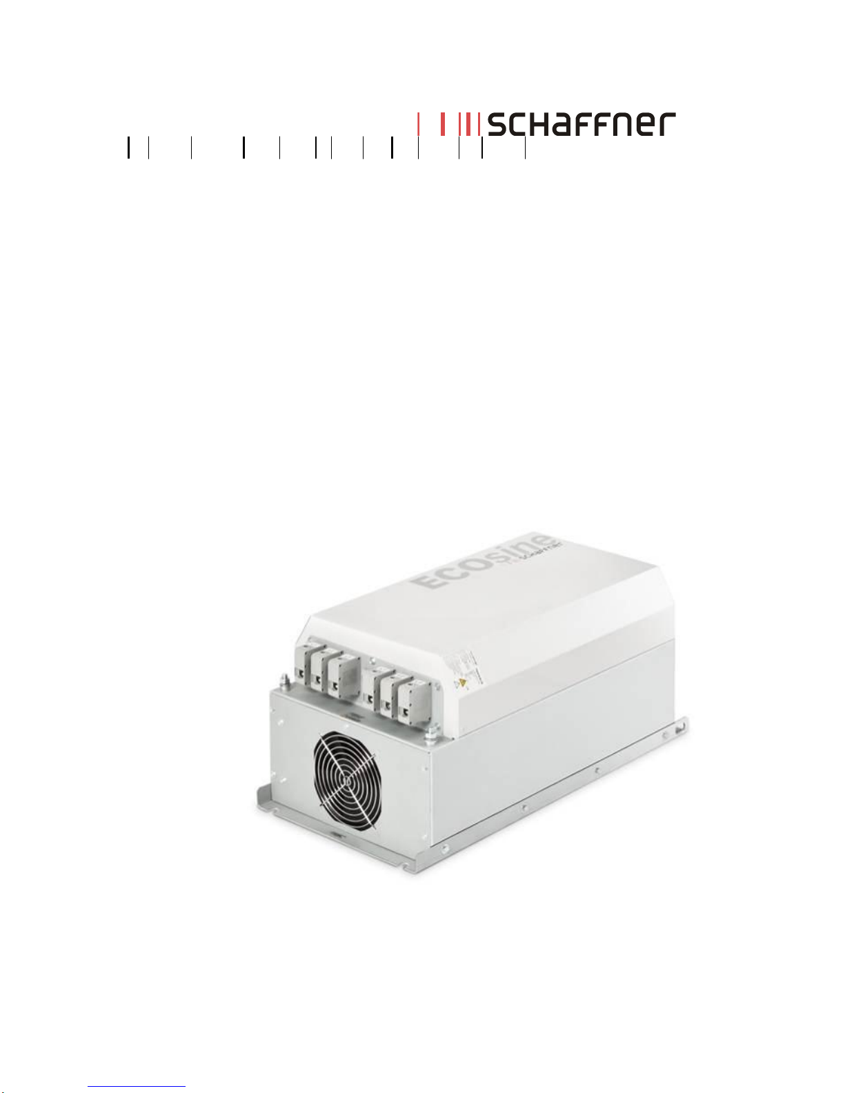
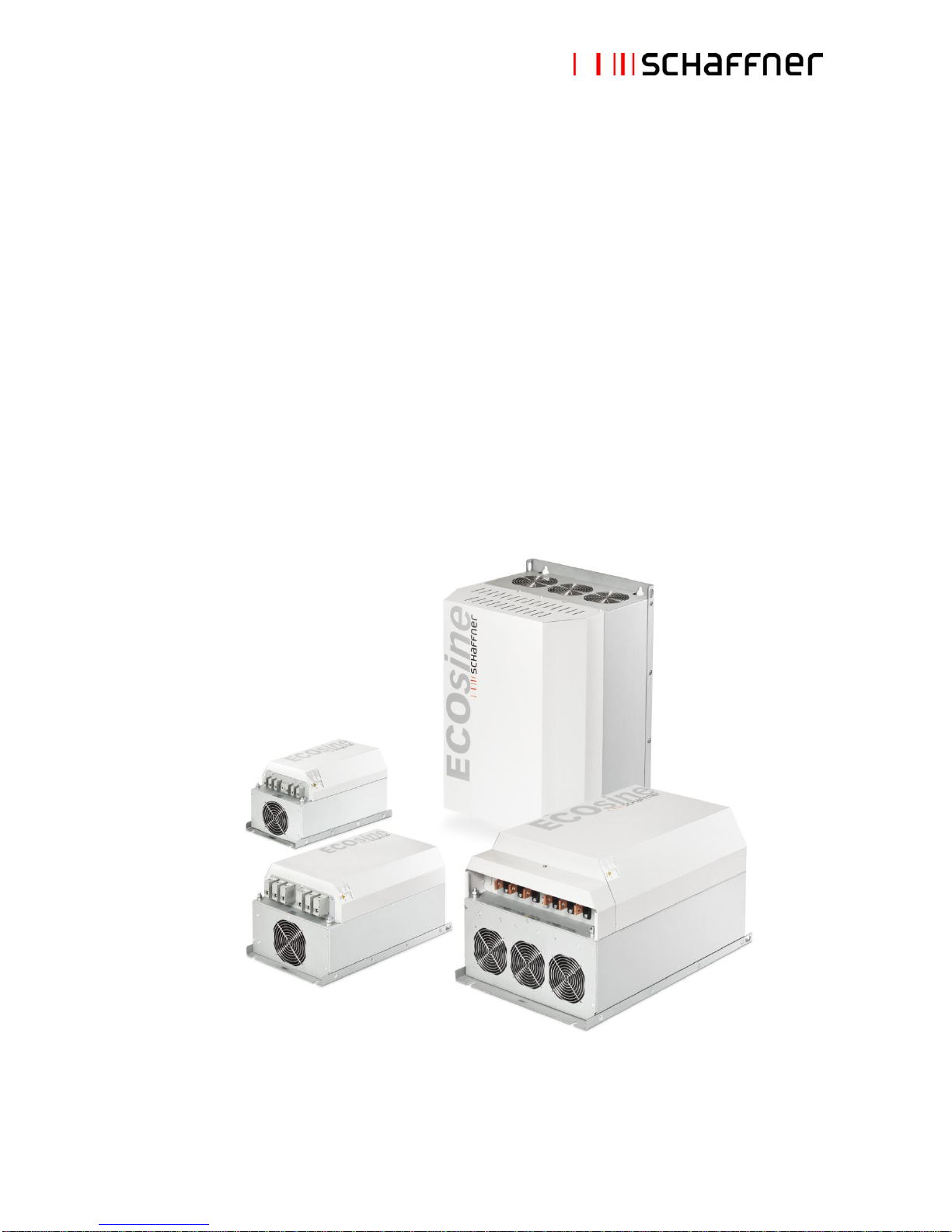
ECOsine™ – Passive Harmonic Filters
FN3416 (50Hz) & FN3418 (60Hz) Economy Line
September 2012
1/43
Page 2
Schaffner Group
User Manual
ECOsine™ – Passive Harmonic Filters Economy Line
September 2012
2/43
ECOsine™ – Passive Harmonic Filters
FN3416 (50Hz) & FN3418 (60Hz) Economy Line
Schaffner ECOsine™ harmonic filters represent an economical solution to the challenge of load-applied
harmonics mitigation in three-phase power systems. With a plug-and-play approach and more compact
dimensions than comparable products, they can be quickly installed and easily commissioned. They
increase the reliability and service life of electrical installations, help utilize electric system capacity
better, and are the key to meet Power Quality standards such EN61000-3-12. ECOsine™ filters help to
reduce the costly waste of electricity.
This user manual is intended to support designers, installers, and application engineers with filter
selection, installation, application and maintenance. For additional helpful tips for overcoming harmonics
mitigation challenges, please also consult the more detailed user manual of the ECOsine™ FN3410
(50Hz) and FN3412 (60Hz) full performance filters.
If you require additional support, please feel free to contact your local Schaffner partner.
Page 3
Schaffner Group
User Manual
ECOsine™ – Passive Harmonic Filters Economy Line
September 2012
3/43
Important user notice
Schaffner ECOsine™ harmonic filters are designed for the operation on the input (grid) side of power
electronic equipment with six-pulse rectifier front-ends in balanced three-phase power systems, like
typically used in AC or DC motor drives and high power DC supplies. Filter suitability for a given
application must be determined by the user on a case by case basis. Schaffner will not assume liability
for any consequential downtimes or damages resulting from use or application of ECOsine™ filters
outside of their specifications. ECOsine™ filters are not designed for single-phase or split-phase
applications.
ECOsine™ filters with protection category IP20/NEMA1 must be mounted in a clean, dry location.
Contaminants such as oils, corrosive vapors and abrasive debris must be kept out of the enclosure.
These filter enclosures are intended for indoor use, primarily to provide a degree of protection against
contact with enclosed equipment. These enclosures offer no protection against airborne contaminants.
Important safety considerations
Note: Filter installation has to be carried out by a trained and certified electrician or technician, who is
familiar with installation and safety procedures in three-phase power systems.
Warning: High voltage potentials are involved in the operation of ECOsine™ filters. Always remove
power before handling energized parts of the filter, and let ample time elapse (> 1 minute) for the
capacitors to discharge to safe levels.
Warning: Follow the installation instructions closely. Ensure that fans and cooling slots are free from
obstructions that could inhibit efficient air circulation. Do not operate the filter in ambient conditions
outside of specifications.
Note: Do not operate ECOsine™ filters on unsymmetrical loads, on linear loads, or with single-phase
equipment.
Note: Always use an upstream disconnect or protection device as required by most national and
international electric codes.
Note: Always connect the filter to protective earth (PE) first, then continue with the wiring of the phase
connectors.
Note: Follow the Schaffner instructions closely when doing maintenance work. Use exclusively spare
parts recommended and approved by Schaffner.
Note: Always practice the safety instructions defined by your company when handling, installing,
operating, or maintaining ECOsine™ harmonic filters.
Note: In case of uncertainty and questions please contact your local Schaffner partner for assistance.
Page 4

Schaffner Group
User Manual
ECOsine™ – Passive Harmonic Filters Economy Line
September 2012
4/43
Content
1. Part number coding ............................................................................................................................... 5
2. Filter description ................................................................................................................................... 6
2.1 General electrical specifications FN 3416 (50Hz filters) .................................................................... 6
2.2 General electrical specifications FN 3418 (60Hz filters) .................................................................... 7
2.3 Additional electrical specifications ..................................................................................................... 8
2.4 Mechanical specifications .................................................................................................................. 9
2.5 Performance characteristics ............................................................................................................ 11
2.6 Function diagram ............................................................................................................................. 14
2.7 External filter elements (Frank: new picture needed) ...................................................................... 15
2.8 Audible noise ................................................................................................................................... 16
3. Filter purpose and function ................................................................................................................ 17
4. Filter selection ..................................................................................................................................... 20
5. Filter application .................................................................................................................................. 23
6. Filter installation .................................................................................................................................. 24
7. Filter maintenance ............................................................................................................................... 29
8. Special considerations ....................................................................................................................... 31
8.1 Over-temperature contact and load disconnect ............................................................................... 31
9. Troubleshooting .................................................................................................................................. 32
10. FAQ – Frequently asked questions ................................................................................................. 33
11. Custom design input form ................................................................................................................ 36
Appendix I: International standards ...................................................................................................... 37
I. Engineering recommendation G5/4-1 ................................................................................................. 37
II. International standard EN 61000-3-12............................................................................................... 39
III. IEEE Std 519-1992 ........................................................................................................................... 42
Appendix II: Declaration of conformity ................................................................................................. 43
Page 5
Schaffner Group
User Manual
ECOsine™ – Passive Harmonic Filters Economy Line
September 2012
5/43
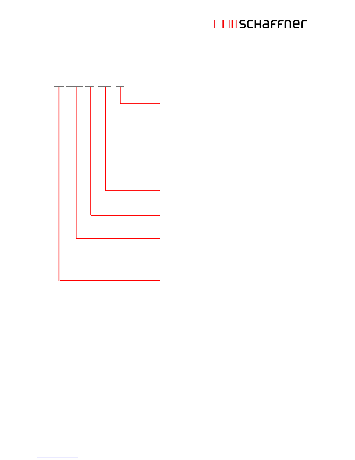
1. Part number coding
FN 34xx xx -xxx -xx
Connection style
33 = safety terminal block 10mm2
34 = safety terminal block 25mm2
35 = safety terminal block 50mm2
40 = safety terminal block 95mm2
44 = safety terminal block 6mm2
99 = copper bus bars in different sizes
Rated, unfiltered load (drive input) current [A]
Blank = standard voltage rating
Filter family
3416 = filter for 50Hz, 380-500V grids
3418 = filter for 60Hz, 380-480V grids
Schaffner standard filter
Examples:
FN 3416-60-34: Filter for 50Hz, 380-500V grids, 60A drive input current, with 25mm2 terminals, for
diode or SCR (thyristor) rectifier front-end.
FN 3418-240-99: Filter for 60Hz, 380-480V grids, 240A drive input current, with copper bus bar,
for diode or SCR (thyristor) front-end.
Page 6
Schaffner Group
User Manual
ECOsine™ – Passive Harmonic Filters Economy Line
September 2012
6/43
2. Filter description
2.1 General electrical specifications FN 3416 (50Hz filters)
Nominal operating voltage:
3x 380 to 500VAC
Voltage tolerance range:
3x 342 to 550VAC
Operating frequency:
50Hz ±1Hz
Network:
TN, TT, IT
Nominal motor drive input current rating: 1)
10 to 320A @ 45°C
Nominal filter input current rating: 1)
7A
rms
to 240A
rms
@ 45°C
Nominal motor drive input power rating:
4 to 200kW
Total harmonic current distortion THID: 2)
According to EN61000-3-12, table 3
<10% @ rated power (with Ldc)
<15% @ rated power (without Ldc)
Total demand distortion TDD: 2)
According to IEEE 519, table 10-3
Partially weighted harmonic distortion PWHID:
<22% @ rated power
Efficiency:
>98% @ nominal line voltage and power
Drive dc-link voltage behavior: 3)
No load: +10%
Full load: -5%
High potential test voltage: 4)
P E 2500VAC (1min)
SCCR: 5)
100kA
Protection category:
IP20
Pollution degree:
1, 2 (according to EN 61800-5-1, EN 50178)
Cooling:
Natural convection cooling (4 to 7.5kW)
Internal forced cooling (11kW and above)
Overload capability:
1.6x rated current for 1 minute, once per hour
2x rated current for 10 seconds, once per hour
5x rated current for 1 second, once per hour
Capacitive current at low load:
<30% of rated input current, at 400VAC
<37% of rated input current, at 500VAC
Ambient temperature range:
-25°C to +45°C fully operational
+45°C to +55°C derated operation 6)
-25°C to +70°C transportation and storage
Flammability class:
UL 94V-2 or better
Insulation class of magnetic components:
H (180°C)
Design corresponding to:
UL 508, EN 61558-2-20, CE (LVD 2006/95/EC)
MTBF @ 45°C/500V (Mil-HB-217F):
200’000 hours
MTTR:
<15 minutes (capacitors and fans)
Lifetime (calculated):
Min. 15 years
Safety monitoring functions:
Over-temperature of magnetic components
Safety monitor output signal:
NO switch
1)
ECOsine™ filters reduce RMS input and peak current by reducing harmonic currents and improving true power factor.
2)
System requirements: THVD <2%, line voltage unbalance <1%
Performance specification for six-pulse diode rectifiers. SCR rectifier front-ends produce different results, depending upon
the firing angle of the thyristors.
3)
Conditions: line impedance <5%
4)
Repetitive tests to be performed at max. 80% of above levels, for 2 seconds.
5)
External UL-rated fuses required.
6)
I
derated
= I
nominal
*(70°C-T
amb
)/25°C
Page 7

Schaffner Group
User Manual
ECOsine™ – Passive Harmonic Filters Economy Line
September 2012
7/43
2.2 General electrical specifications FN 3418 (60Hz filters)
Nominal operating voltage:
3x 380 to 480VAC
Voltage tolerance range:
3x 342 to 528VAC
Operating frequency:
60Hz ±1Hz
Network:
TN, TT, IT
Nominal motor drive input current rating: 1)
8 to 310A @ 45°C
Nominal filter input current rating: 1)
5A
rms
to 250A
rms
@ 45°C
Nominal motor drive input power rating:
5 to 250HP
Total harmonic current distortion THID: 2)
According to EN61000-3-12, table 3
<10% @ rated power (with Ldc)
<15% @ rated power (without Ldc)
Total demand distortion TDD: 2)
According to IEEE 519, table 10-3
Partially weighted harmonic distortion PWHID:
<22% @ rated power
Efficiency:
>98% @ nominal line voltage and power
Drive dc-link voltage behavior: 3)
No load: +10%
Full load: -5%
High potential test voltage: 4)
P E 2500VAC (1min)
SCCR: 5)
100kA
Protection category:
IP20
Pollution degree:
1, 2 (according to EN 61800-5-1, EN 50178)
Cooling:
Natural convection cooling (5 to 15HP)
Internal forced cooling (20HP and above)
Overload capability:
1.6x rated current for 1 minute, once per hour
2x rated current for 10 seconds, once per hour
5x rated current for 1 second, once per hour
Capacitive current at low load:
<30% of rated input current, at 460VAC
Ambient temperature range:
-25°C to +45°C fully operational
+45°C to +55°C derated operation 6)
-25°C to +70°C transportation and storage
Flammability class:
UL 94V-2 or better
Insulation class of magnetic components:
H (180°C)
Design corresponding to:
UL 508, EN 61558-2-20, CE (LVD 2006/95/EC)
MTBF @ 45°C/460V (Mil-HB-217F):
200’000 hours
MTTR:
<15 minutes (capacitors and fans)
Lifetime (calculated):
Min. 15 years
Safety monitoring functions:
Over-temperature of magnetic components
Safety monitor output signal:
NO switch
1)
ECOsine™ filters reduce RMS input and peak current by reducing harmonic currents and improving true power factor.
2)
System requirements: THVD <2%, line voltage unbalance <1%
Performance specification for six-pulse diode rectifiers. SCR rectifier front-ends produce different results, depending upon
the firing angle of the thyristors.
3)
Conditions: line impedance <5%
4)
Repetitive tests to be performed at max. 80% of above levels, for 2 seconds.
5)
External UL-rated fuses required.
6)
I
derated
= I
nominal
*(70°C-T
amb
)/25°C
Page 8
Schaffner Group
User Manual
ECOsine™ – Passive Harmonic Filters Economy Line
September 2012
8/43
2.3 Additional electrical specifications
ECOsine™ passive general electrical specifications refer to operating altitudes up to 1000m a.s.l.
(3300ft). Operation between 1000m and 4000m (3300ft and 13123ft) requires a derating according to the
table below:
80
85
90
95
100
105
0 500 1000 1500 2000 2500 3000 3500 4000
Altitude a.s.l. [m]
Rated load power [%]
Note: do not use ECOsine™ passive harmonic filters in altitudes above 4000m without consulting
Schaffner first.
ECOsine™ passive filters have been designed and certified acc. UL508, resp. UL508C, so there is no
limitation in terms of altitude up to 4000m for clerance and creepage.
Page 9
Schaffner Group
User Manual
ECOsine™ – Passive Harmonic Filters Economy Line
September 2012
9/43
2.4 Mechanical specifications
Page 10
Schaffner Group
User Manual
ECOsine™ – Passive Harmonic Filters Economy Line
September 2012
10/43
Page 11
Schaffner Group
User Manual
ECOsine™ – Passive Harmonic Filters Economy Line
September 2012
11/43
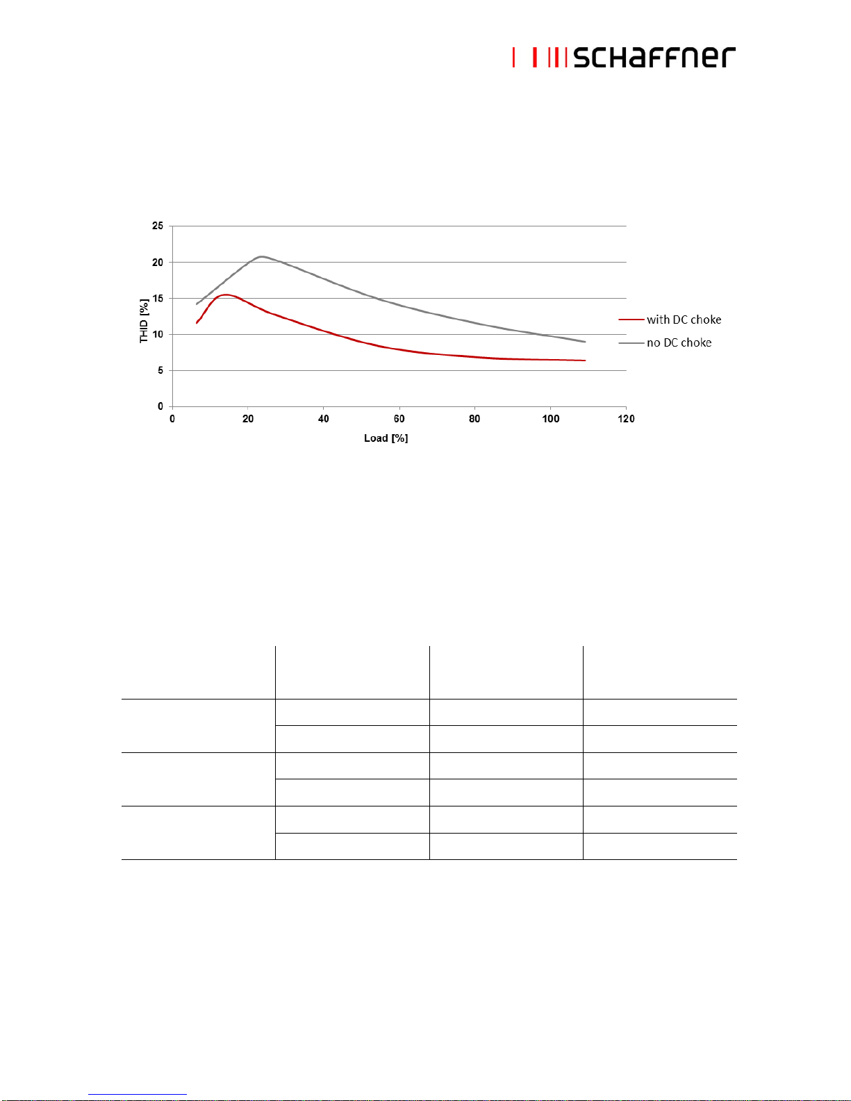
2.5 Performance characteristics
THID vs. load (diode rectifier front-ends)
Note: shown above is the typical performance characteristic of FN3416/18 series in balanced diode
rectifier front-end applications, with and without DC-link choke. In SCR rectifier applications, filter
performance greatly depends upon the firing angle of the thyristors.
Note: the values of EMI-filter components present in the same non-linear load (e.g. motor drive) can
influence the mitigation performance of passive harmonic filters. For Schaffner FN3418 (60Hz) filters the
following boundary conditions exist for the smallest frame sizes:
Filter
Typical
drive dc-linke choke
Max. recommended
EMI-filter X-capacitor
Expected THID *
FN3418-8-44
8.4mH
≤ 1.0µF
~10%
-
≤ 2.2µF
~15%
FN3418-11-44
6.7mH
≤ 1.5µF
~10%
-
≤ 1.5µF
~13%
FN3418-15-44
4.2mH
≤ 3.3µF
~10%
-
≤ 3.3µF
~15%
* System requirements: THVD <2%, line voltage unbalance <1%
All other FN3416 and FN3418 filters are not subject to any such limitations.
Page 12
Schaffner Group
User Manual
ECOsine™ – Passive Harmonic Filters Economy Line
September 2012
12/43
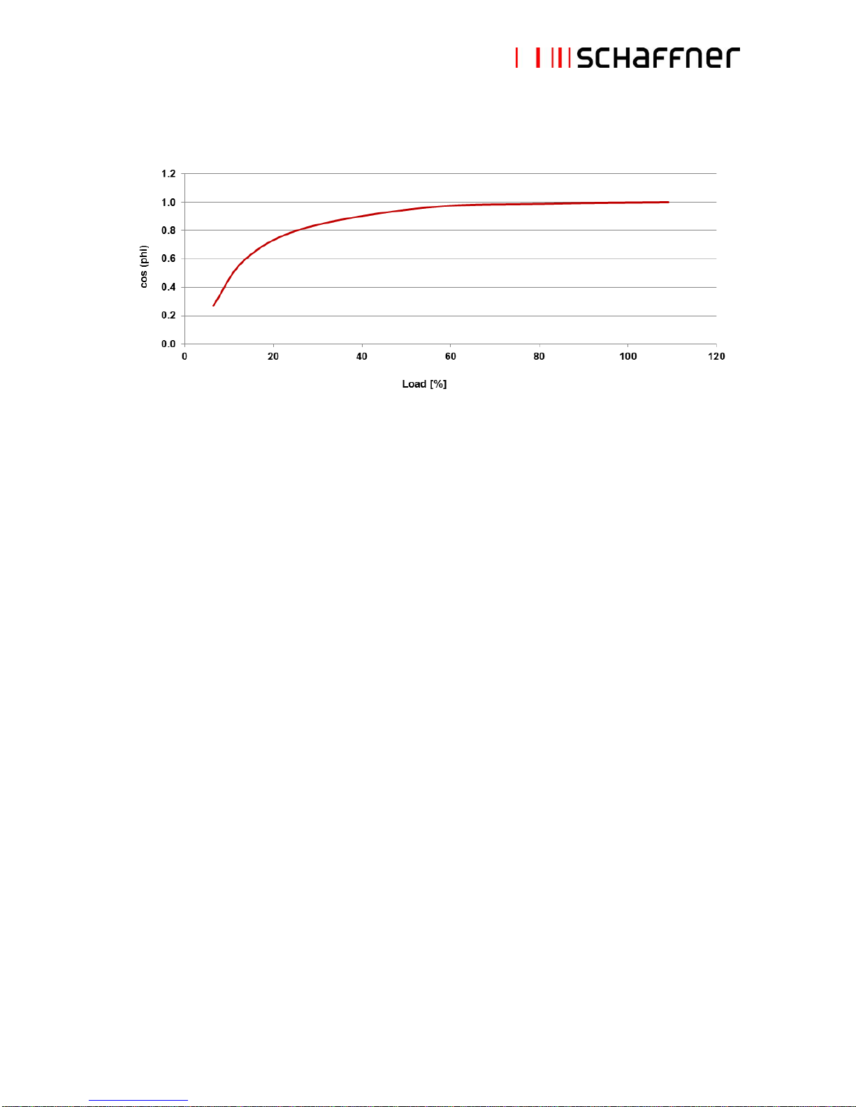
Power factor vs. load (diode rectifier front-ends)
Note: in SCR rectifier applications, filter characteristics greatly depend upon the firing angle of the
thyristors.
Page 13
Schaffner Group
User Manual
ECOsine™ – Passive Harmonic Filters Economy Line
September 2012
13/43
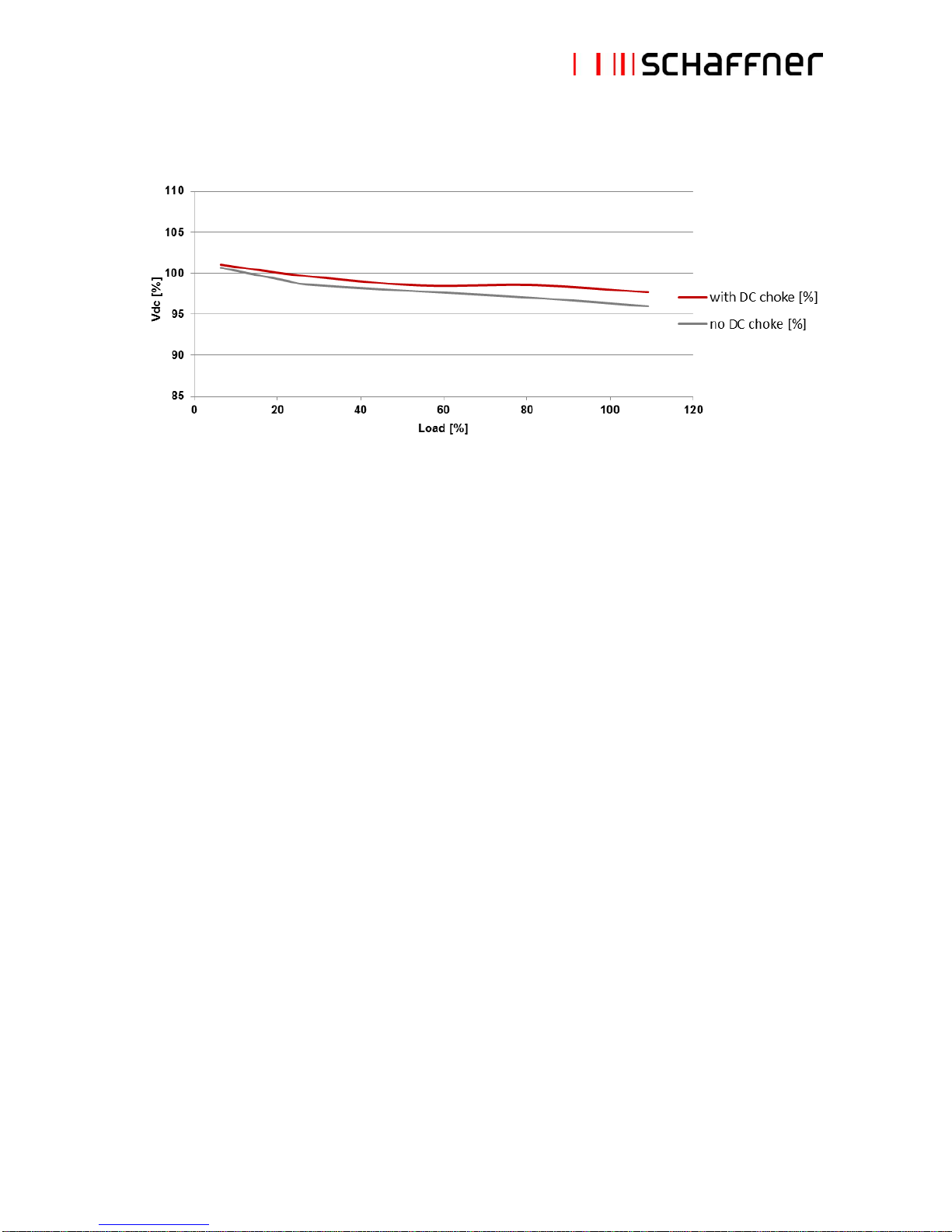
Drive dc-link voltage vs. load (diode rectifier front-ends)
Note: in SCR rectifier applications, filter characteristics greatly depend upon the firing angle of the
thyristors.
Page 14

Schaffner Group
User Manual
ECOsine™ – Passive Harmonic Filters Economy Line
September 2012
14/43
2.6 Function diagram
In-Out choke
Power capacitors
Trap choke
Power
supply
Fan
L1
L2
L3
L1'
L2'
L3'
Line Load
PE PE
NC
C
Filter terminals
Line
3 touch safe terminal blocks (busbar terminals >240A)
Load
3 touch safe terminal blocks (busbar terminals >240A)
Over-temperature
NC switch, 250VAC/2.5A, touch safe terminal 4mm2
contact
Open position indicates error
PE
Protective earth. Threaded studs with washer and nut
Function blocks
Chokes
Power magnetic components incl. over-temparature switch
Capacitors
Power capacitors incl. discharge resistors
Fan *
Field replaceable fan for choke cooling (some models)
Power supply *
Internally generated 24VDC for fan supply (some models)
* the followinging filters do not require forced cooling and therefore have no internal fan and power
supply: FN3416-10, -13, -16; FN3418-8, -11, -15.
Page 15

Schaffner Group
User Manual
ECOsine™ – Passive Harmonic Filters Economy Line
September 2012
15/43
2.7 External filter elements
Line terminals (3) Over temperature contact (2) Load terminals (3)
PE terminals (2) Fan(s)
Line terminals (3) Over temperature contact (2) Load terminals (3)
PE terminals (2) Fans
Page 16

Schaffner Group
User Manual
ECOsine™ – Passive Harmonic Filters Economy Line
September 2012
16/43
2.8 Audible noise
Tests have been performed at nominal filter load. Ambient noise level: 49dB[A]
Filter
FN 3416-13-44 (P=5.5kW)
60dB[A] @ 1m
FN 3416-210-40 (P=110kW)
70dB[A] @ 1m
Equipment used: Peak Tech Sound Level Meter 5055
Page 17

Schaffner Group
User Manual
ECOsine™ – Passive Harmonic Filters Economy Line
September 2012
17/43
3. Filter purpose and function
ECOsine™ harmonic filters are based on passive LCR filtering technology. They are intended for the
operation on the input side of balanced three-phase six-pulse rectifiers, like commonly used in inverters
for motor drives.
ECOsine™ Motor drive Motor
Six-pulse rectifiers inherently draw current in a non-sinusoidal fashion from the grid, creating a current
wave form rich in harmonics. Harmonic currents flow through system impedances and create harmonic
voltages. Both harmonic currents and voltages give raise to serious issues, such as electric system
overload, reliability problems, and violations against international standards and utility codes.
ECOsine™ filters efficiently reduce the harmonic currents to negligible levels and ensure, that a sinewave current is drawn from the grid. In the process, they also reduce peak currents and RMS input
current, allowing for lower wire cross sections in conductors, smaller fuses, breakers, and transformers.
In existing installations, more drives can be used on the same distribution transformer.
The examples on the next pages visualize typical performance test results with and without a Schaffner
ECOsine™ harmonic filter FN 3416-210-40 for the rated load power of 110kW.
M
3~
Page 18

Schaffner Group
User Manual
ECOsine™ – Passive Harmonic Filters Economy Line
September 2012
18/43
Example 1: motor drive without built-in DC-link choke
Without ECOsine™ filter With ECOsine™ filter
Voltage and current waveforms
Voltage and current waveforms
Current harmonics THD = 76.9%
Current harmonics THD = 11.6%
Current harmonics THD, H5, H7, H11, H13, H17, H19, H23
Current harmonics THD, H5, H7, H11, H13, H17, H19, H23
Page 19

Schaffner Group
User Manual
ECOsine™ – Passive Harmonic Filters Economy Line
September 2012
19/43
Example 2: motor drive with built-in DC-link choke
Without ECOsine™ filter With ECOsine™ filter
Voltage and current waveforms
Voltage and current waveforms
Current harmonics THD = 45.1%
Current Harmonics THD = 7.9%
Current harmonics THD, H5, H7, H11, H13, H17, H19, H23
Current harmonics THD, H5, H7, H11, H13, H17, H19, H23
Page 20

Schaffner Group
User Manual
ECOsine™ – Passive Harmonic Filters Economy Line
September 2012
20/43
4. Filter selection
ECOsine™ harmonic filters need to be carefully selected in order to enjoy maximum benefits.
Step 1: supply frequency
Determine, whether the system in question will be operated in a 50Hz or 60Hz electricity grid, and select
the corresponding filter family according to the following table:
50Hz grid
Europe, Middle East, parts of Asia, parts of South America
FN 3416
60Hz grid
North and Central America, parts of Asia, parts of South America
FN 3418
Note: a 50Hz filter will not provide satisfying harmonics mitigation in a 60Hz grid, and vice versa.
Step 2: supply voltage and configuration
Verify, that the supply voltage and configuration is suitable for standard ECOsine™ harmonic filters
according to the following table:
50Hz grid
Nominal voltage 380-500VAC ±10%
TN, TT, IT configuration
60Hz grid
Nominal voltage 380-480VAC ±10%
TN, TT, IT configuration
Note: filters for 690V/50Hz or 600V/60Hz are available upon request.
Step 3: real rectifier/drive input power
The individual filter must be selected by the actual rectifier/drive input real power (kW, HP). It is
important to select the filter as close as possible to the effective input power of the rectifier/drive.
Note that FN 3416 (50Hz) filters show double ratings in the selection table. Depending upon the grid
voltage, the same filter is rated for two different rectifier/drive input real power values. For 380/400/415V
lines, the filters have a lower power rating than for 500V systems.
Note that if the rectifier/drive is being operated very close to its rated power, then the filter can be
selected by the motor drive’s nominal power rating. However, if the drive will be operated e.g. at only
66% of its rated power, then a smaller filter should be selected in order to get maximum harmonics
mitigation performance and the optimum in terms of filter cost, size, and weight.
Page 21

Schaffner Group
User Manual
ECOsine™ – Passive Harmonic Filters Economy Line
September 2012
21/43
Please refer to the following examples:
Example 1:
Power line rating: 400V, 50Hz
Drive rating: 380-500V, 50-60Hz, 15kW, 22.5A, diode rectifier
Planned rectifier/drive input real power: 15kW (100% of drive rating)
Recommended filter according to the filter selection table FN 3416: Type FN 3416-32-33
Example 2:
Power line rating: 500V, 50Hz
Drive rating: 380-500V, 50-60Hz, 15kW, 22.5A, diode rectifier
Planned rectifier/drive input real power: 15kW (100% of drive rating)
Recommended filter according to the filter selection table FN 3416: Type FN 3416-24-33
Example 3:
Power line rating: 400V, 50Hz
Drive rating: 380-500V, 50-60Hz, 15kW, 22.5A, diode rectifier
Planned rectifier/drive input real power: 10kW (66% of drive rating)
Recommended filter according to the filter selection table FN 3416: Type FN 3416-24-33
Example 4:
Power line rating: 500V, 50Hz
Drive rating: 380-500V, 50-60Hz, 15kW, 22.5A, diode rectifier
Planned rectifier/drive input real power: 10kW (66% of drive rating)
Recommended filter according to the filter selection table FN 3416: Type FN 3416-16-44
Overrating the filter does never make sense, because of the inherent lower harmonics mitigation
performance at light load, as well as higher price, size, and weight.
Please refer to the selection tables on the next page.
Page 22

Schaffner Group
User Manual
ECOsine™ – Passive Harmonic Filters Economy Line
September 2012
22/43
Filter selection table FN 3416 (50Hz)
Filter selection table FN 3418 (60Hz)
Page 23

Schaffner Group
User Manual
ECOsine™ – Passive Harmonic Filters Economy Line
September 2012
23/43
5. Filter application
ECOsine™ filters are designed as “load-applied” filters. In contrary to “bus-applied” filters, which are
being installed e.g. at the main power bus of a building, they are specifically designed to be used with
either an individual non-linear load, or with a group of non-linear loads.
One advantage of load-applied filtering is the fact that the upstream power (relative to the harmonic filter)
is clean. This can be of vital importance when the same power bus supplies both motor drives and
sensitive loads. One example could be the elevator drives or HVAC drives in a hospital, where power
must be very clean for all the sensitive medical devices. In such a case, it would not be sufficient to use
a central harmonic filter at the PCC for IEEE Std 519-1992 compliance purposes.
ECOsine™ filters are also suitable for paralleling lower power non-linear loads on a higher power
harmonic filter to improve overall system economy. In this case the total expected load power of all
connected drives must match the filter.
Mains
ECOsine
Non-linear load 1: 30kW/400VAC
Non-linear load 2: 75kW/400VAC
FN3416-210-40
(110kW/400VAC)
If the expected input power exceeds the rating of the largest available filter, and a custom solution is not
desired, then two or more filters can be wired in parallel. In this mode of operation, it is recommended to
use filters with equal power ratings to ensure proper current sharing.
Mains
ECOsine
ECOsine
Non-linear load: 300kW / 500VAC
2x FN3416-260-99
(2x 160kW/500VAC)
AC line reactors are not required when ECOsine™ filters are installed. For a new system, this helps to
offset a good portion of the harmonic filter cost. If a harmonic filter is added to a drive with an existing AC
line reactor, it is recommended to remove the reactor if possible.
Page 24

Schaffner Group
User Manual
ECOsine™ – Passive Harmonic Filters Economy Line
September 2012
24/43
6. Filter installation
Please follow the few simple steps below to ensure a safe and satisfying filter function for many years.
Step 1: Visual inspection
All Schaffner ECOsine™ filters have undergone rigorous testing before they left our ISO 9001:2008
certified factory. They are packaged with great care in a sturdy container for international shipment.
However, carefully inspect the shipping container for damage that may have occurred in transit. Then
unpack the filter and carefully inspect for any signs of damage. Save the shipping container for future
transportation of the filter.
In the case of damage, please file a claim with the freight carrier involved immediately and contact your
local Schaffner partner for support. Under no circumstances install and energize a filter with visible
transportation damage.
If the filter is not going to be put in service upon receipt, store within the original container in a clean, dry
location, free of dust and chemicals.
Step 2: Mounting
ECOsine™ load-applied filters are best installed as close as possible to the non-linear load in question.
Ideally they are mounted next to the rectifier or motor drive inside the electrical cabinet or control room.
Unlike ECOsine™ full performance filters FN3410/11/12/13, all sizes of FN3416/18 come in designs for
vertical wall mounting.
Note: Filters for vertical wall mounting must not be installed horizontally. Horizontal installation will
negatively affect air flow and the life time of the filter.
Important:
In order to ensure sufficient air flow, keep a
clearance of min.150mm above and below the
filter to walls or other components. A 20mm
clearance on either side is recommended for the
possibility to comfortably open the cover in case
of field maintenance.
It must be ensured that the environmental
temperature is kept below 45°C with appropriate
thermal management (e.g. cabinet cooling). Filter
operation in warmer environments require
temperature derating.
ECOsine™
Drive
>150mm
>150mm
>20mm
Page 25

Schaffner Group
User Manual
ECOsine™ – Passive Harmonic Filters Economy Line
September 2012
25/43
2.1
Drilling pattern for wall mounted filters:
FN 3416
FN 3418
H W D
-10, -13, -16
-8, -11, -15
370
140
M8
-24, -32, -38, -45
-21, -28, -35, -41
435
200
M10
-60, -75
-53, -65
500
225
M10
-90, -110
-80, -105
555
225
M10
-150, -180, -210
-260, -320
-130, -160, -190
-240, -310
665
350
M12
All dimensions in mm; 1 inch = 25.4mm
Note: the numbers (e.g. -10) are in reference to the middle
part of the ECOsine part number coding (e.g. FN 3416-10-44)
H
W
D
2.2
Bolt selection: Schaffner recommends zinc coated hex ribbed
flange steel bolts. Respect filter weight for appropriate choice
of bolts! Head diameters must not exceed these dimensions:
M8: d ≤ 18.2mm, M10: d ≤ 21.2mm M12: d ≤ 25mm
2.3
Filter placement:
1. Set bolts loose into wall, leave 5mm distance from head to
wall.
2. Lift filter with appropriate hoist, using lifting eye bolt
(attached in package) – smallest types (up to 20kg) may be
lifted manually by two persons (no lifting eye bolt
applicable).
3. Place filter first onto lower bolts...
4. ...then position it through backplane head openings on upper
bolts.
5. Fix bolts with appropriate torque (depending upon the
material of the back plane and local standards).
d
3.
4.
Page 26

Schaffner Group
User Manual
ECOsine™ – Passive Harmonic Filters Economy Line
September 2012
26/43
Step 3: Wiring
3.1
Verify safe disconnection of all line side power.
Consult your local safety instructions.
3.2
Safety cover for filters with bus-bar terminals.
The filters with bus-bar terminals (FN 3416-260/320-99,
FN 3418-240/310-99) are equipped with a terminal
cover for safety reasons.
Untighten the bolt on the front side to remove the
cover.
3.3
Connect protective earth (PE) wire to adequate
earth potential close to ECOsine™ filter.
Use a wire diameter of equal or bigger size as foreseen
for line/load side power cables – according to your local
codes and safety instructions.
3.4
Connect PE wire to min. one available PE bolt
with appropriate cable lug to threaded stud.
max. torque M6: 4Nm
max. torque M8: 10Nm
max. torque M10: 18Nm
3.5
Connect ECOsine™ load side terminals L1’, L2’, L3’
to respective motor drive or rectifier inputs.
Last two digits of ECOsine™ part number, i.e.
FN 3418-65-34, indicate terminal type. See table to the
right for recommended wire size and torque.
Use stranded copper wire with a temperature rating of
75°C or higher.
Terminal
Wire
Torque
AWG
mm2
Nm
-44 8 6
1.0 - 1.2
-33 6 10
1.5 - 1.8
-34 2 25
4.0 - 4.5
-35
1/0
50
7.0 - 8.0
-40
4/0
95
17 - 20
-99
6/0
150
25 - 30
ECOsine™
Drive
>150mm
>150mm
>20mm
Page 27

Schaffner Group
User Manual
ECOsine™ – Passive Harmonic Filters Economy Line
September 2012
27/43
3.6
Connect over-temperature contact
The over-temperature contact is a relay contact, which
is open in ALARM state. Its load rating is
250VAC/30VDC/2.5A. It may either be used to
remotely disconnect the drive’s load via respective
input of drive control (check drive manual) or as alarm
sensor for system control unit.
AN ENGAGED OVERTEMPERATURE CONTACT MUST
LEAD TO IMMEDIATE LOAD
SHUTDOWN AND INVESTIGATION
OF THE PROBLEM.
3.7
Connect ECOsine™ line side terminals L1, L2, L3
to power input protection (current limiting fuses – see below).
3.8
Fuses
ECOsine™ filters need external over-current protection for compliance with UL/cUL standard.
Fuses and associated fuseholders must be UL listed and rated for 100kA SCCR supplies. The
subsequent list shows requested fuse current ratings for UL class J and, where UL compliance is
not mandatory, for IEC class gG. The fuse rating is independent of the supply voltage.
ECOsine™ type
Fuse class J
FN 3418
rated A
FN 3418-8-44
8
FN 3418-11-44
10
FN 3418-15-44
15
FN 3418-21-33
25
FN 3418-28-33
30
FN 3418-35-33
35
FN 3418-41-33
45
FN 3418-53-34
60
FN 3418-65-34
70
FN 3418-80-35
90
FN 3418-105-35
110
FN 3418-130-40
150
FN 3418-160-40
175
FN 3418-190-40
225
FN 3418-240-99
300
FN 3418-310-99
350
ECOsine™ type
Fuse class J
Fuse class gG
All FN 3416
rated A
rated A
FN 3416-10-44
10
10
FN 3416-13-44
15
10
FN 3416-16-44
20
16
FN 3416-24-33
25
20
FN 3416-32-33
35
35
FN 3416-38-33
40
35
FN 3416-45-33
50
50
FN 3416-60-34
75
63
FN 3416-75-34
80
80
FN 3416-90-35
100
100
FN 3416-110-35
150
125
FN 3416-150-40
175
160
FN 3416-180-40
200
200
FN 3416-210-40
250
224
FN 3416-260-99
300
250
FN 3416-320-99
350
300
Page 28

Schaffner Group
User Manual
ECOsine™ – Passive Harmonic Filters Economy Line
September 2012
28/43
A system with multiple ECOsine™
filters paralleled for a high power load
need each a separate 3-phase line side
fuse block, corresponding to the
respective filter and according to above
table.
The drive’s application manual may
prescribe line-side fuse protection as
well, which in this case either
corresponds to the sum of the filter fuse
ratings or, if lower, would request
separate drive fuses at its input.
An application, having one ECOsine™
filtering harmonics of several drives,
requires in any case line side fuse
protection of the drives as well as the
correct filter protection according to
above table.
3.9
Safety cover for filters with bus-bar
terminals.
Once all filter terminals are properly
wired, replace the safety cover by
tightening the previously untightened
bolt.
ECOsine™
DRIVE 1
DRIVE 2
DRIVE 3
FUSE
FUSE
FUSE
FUSE
M M M
DRIVE M ECOsine™ 1
ECOsine™ 2
ECOsine™ 3
FUSE
FUSE
FUSE
Page 29

Schaffner Group
User Manual
ECOsine™ – Passive Harmonic Filters Economy Line
September 2012
29/43
7. Filter maintenance
Schaffner ECOsine™ filters are reliable low maintenance products. Many products like power supplies,
inverters, or motor drives utilize fans for forced cooling to minimize the size and weight. ECOsine™
filters are designed with a similar temperature management concept and therefore, fans may have to be
maintained and replaced in certain intervals to sustain the function and value of the product. Fans are
100% field replaceable without the need to uninstall and disconnect the filter.
LINE SIDE POWER MUST BE SWITCHED OFF PRIOR TO REPLACEMENT OF FAN.
Warning:
Power electronic devices like motor drives contain large capacitors which may retain perilous charges for
a period of time. Before opening the cabinet or device, disconnect the supply power and let ample time
elapse (> 1 minute) for the capacitors to discharge to safe levels. Use a meter to check terminal voltages
before touching or handling!
Maintenance considerations:
Schaffner harmonics filters are equipped with long life components that ensure a satisfactory function for
many years under normal operating conditions. Any operation under extreme conditions such as overtemperatures, overvoltage situations, polluted environments etc. reduces the life expectancy.
Under normal operating conditions (ambient temp at 45°C) and with the filter permanently at full load, the
fan(s) run at 100% duty cycle. This translates roughly to a 10 year maintenance-free life time.
Nevertheless, it is recommended to check the functionality at least in a 2 year interval, when a ‘normal
100% load’ situation is given. More severe operating conditions may require shorter service intervals.
Indications for required fan replacement: - increased audible noise coming from the fan
- after 50,000 hours.
Power capacitor damage may be caused by severe abnormal supply voltage peaks (i.e. lightning –
depending upon system protection), but may only be recognizable through the measurement of line side
harmonics distortion. This may be indicated with a modern energy meter or by regular checkup with a
distortion analyzer. According to the above considerations, a 2 year inspection interval is advisable. An
inspection should as well be performed after extreme overvoltage situations.
Field replacement of power capacitors is possible, but must be executed by trained Schaffner personnel.
Indications for required capacitor replacement: - performance loss (THID out of spec)
- visible capacitor damage
Page 30

Schaffner Group
User Manual
ECOsine™ – Passive Harmonic Filters Economy Line
September 2012
30/43
Fan specifications:
Supply voltage:
24VDC
Power:
max. 7W
Size:
120x120x25mm, fixation holes 105x105mm, Ø4.3mm
Air flow:
min. 110CFM
Connection:
min. 150mm cable length, TYCO MTA-100 plug, 2 poles (pin 1 = +24VDC)
Recommended types:
SUNON PMD2412PTB3-A
NMB-MAT 4710KL-05W-B50
Fan replacement instructions:
1
Disconnect line side power.
Let ample time elapse (> 1 minute) for the capacitors to discharge to safe levels.
Check with voltage meter before proceeding. Consult your local safety instructions.
2
Untighten bolts (5x) of fan plate at bottom side of filter.
3
Pull out fan connector plug (1x).
4
Disassemble fan from plate (4 bolts).
5
Mount a new fan with appropriate plug (isolation tube and plug of old fan may be used again;
appropriate tool for IDC connection needed). Pay attention to the polarity of the plug.
6
Connect fan to plug socket, re-assemble fan plate.
Step 2
Step 3
Steps 4, 5
Page 31

Schaffner Group
User Manual
ECOsine™ – Passive Harmonic Filters Economy Line
September 2012
31/43
8. Special considerations
8.1 Over-temperature contact and load disconnect
ECOsine™ harmonic filters provide basic safety monitoring:
temperature detection level for each inductive component (over-temperature contact)
This alarm indication requires adequate reaction in order to prevent possible system damage (i.e. cable
or cabinet overheating). Either the cabinet safety monitoring unit must make use of the alarm contact, or
the contact must directly control a stop function of a connected motor drive (refer to motor drive user
manual for applicability).
Important:
Connection and use of the over-temperature contact is required for safe operation. An engaged (open)
over-temperature contact must lead to immediate load shutdown and investigation of the problem.
Technical data of over-temperature contact:
Error status:
Switch open
Switching power:
max. 2.5A/250VAC or 30VDC
Technology:
Bi-metal switch (potential-free)
Safety:
UL 2111
Note: The described applications of the monitor contact are proposals. Please respect local and national
safety directives.
Page 32

Schaffner Group
User Manual
ECOsine™ – Passive Harmonic Filters Economy Line
September 2012
32/43
9. Troubleshooting
Schaffner ECOsine™ harmonic filters are high quality products and have undergone rigorous testing and
qualification procedures. Every unit runs through a 100% test in our ISO 9001:2008 factories. There are
no troubles to be expected if the filter is installed, operated, and maintained as described in this
document and within published specifications.
In the unlikely event of a problem, please contact your local Schaffner partner for assistance.
Page 33

Schaffner Group
User Manual
ECOsine™ – Passive Harmonic Filters Economy Line
September 2012
33/43
10. FAQ – Frequently asked questions
Q:
Why are ECOsine™ harmonic filters CE-marked, but Schaffner EMI filters are not?
A:
EMI filters and other passive components must not be CE-marked according to the low-voltage
directive because they are not sold to the public as an individual device with an independent
function. They are usually part of equipment, which in turn has to be CE-marked as a whole. This
is different with e.g. a transformer or a harmonic filter. ECOsine™ can be sold as an individual
aftermarket product that will not necessarily be built into another CE-conform piece of equipment.
As a “stand-alone unit”, it must be CE-marked in order to be distributed throughout Europe.
Q.
Can ECOsine™ filters be used for a single-phase load or just be connected to two phases?
A:
This mode of operation is not possible. ECOsine™ filters are optimized for balanced three-phase
power systems with six-pulse rectifier front ends and their performance depends upon voltage
distortion and phase unbalance. Schaffner is experienced in custom harmonic filter design and can
potentially come up with a single-phase solution to your requirement.
Q:
How are ECOsine™ harmonic filters contributing to financial savings? Are they reducing my
electricity bill?
A:
ECOsine™ harmonic filters help to save long term system operating cost and help to avoid
expensive system/production downtime. There are two different aspects to answer this question:
1. Most likely, the installation of ECOsine™ filters will not result in a lower electricity bill.
ECOsine™ harmonic filters substantially reduce reactive current and thus reactive power
in the system. However, most utility companies invoice only the consumption of real
power, which will not be changed with the installation of ECOsine™. Some utilities may
issue penalties for consumers with low power factor (usually <0.9). Low power factor can
be caused by phase shift of the fundamental current (low cos phi) and/or by harmonics of
the current (high THID) as it is described by the following formula:
For nonlinear loads (like six-pulse rectifiers) value of cos phi is high (close to 1) and the
main reason for a reduced power factor is a high value of THID. The installation of
ECOsine™ filters would increase the power factor and help to avoid utility penalties, i.e.
get into a less expensive rate class. These penalty schemes are different from country to
country and from utility company to utility company.
2. Electric systems with significant non-linear loads have high levels of harmonic current
distortion and consequently also bad voltage quality. Both can have significant negative
effects, such as:
Transformers
Increased audible noise
Increase in copper losses (due to current harmonics)
Increase in iron losses (due to voltage harmonics)
Power installation with capacitive power factor compensators
Risk of resonance and resulting damage of capacitor banks
Power cables
Increased heating
Risk of insulation failure if involved in system resonance
Page 34

Schaffner Group
User Manual
ECOsine™ – Passive Harmonic Filters Economy Line
September 2012
34/43
Motors and Generators
Increased heating due to iron and cooper losses at the harmonic frequencies
(performance reduced to 90%)
Higher audible noise
Refusal to start smoothly (cogging)
Very high slip in induction motors (crawling)
Potential of mechanical oscillations in a turbine-generator or motor-load systems
Pulsating or reduced torques
Capacitors
Increased heating and voltage stress
Reduced capacitors life
Electronic Equipment
Wrong operation of equipment dependent upon accurate determination of the line
voltage wave shape (e.g. zero crossing)
Problems caused by transmission of ac supply harmonics (via power supply or
magnetic coupling) into equipment components
Erratic (sometimes subtle) malfunctions of computers, programmable controllers,
medical instruments etc. (in some cases, having very serious consequences)
Metering (watt-hour meters)
Possible erroneous operation with both positive and negative errors (distortion must be
severe >20%)
Switchgear and Relaying
Increased heating and thus reduced steady-state current carrying capability
Fuses suffer derating
Complete definition of relay response impossible
Older circuit breakers (responding to peak currents) may cause nuisance tripping
Communication Equipment
Telephone interferences (audible harmonic frequencies)
ECOsine™ harmonic filters substantially reduce harmonic currents and therefore basically convert
a non-linear load into a linear load. This eliminates the risk for most of the above problems. Lower
harmonic currents help to relieve the entire electrical installation from excessive loading and
heating, allow more consumers to be powered by the same (existing) installation, and help to
postpone expensive electrical system upgrades when retrofitting additional non-linear consumers.
ECOsine™ filters also reduce the risk of harmonics-related system downtimes which can have
tremendous financial consequences e.g. in a semiconductor manufacturing line or a banking
center. Last but not least, lower harmonic currents cause less harmonic voltages when flowing
through system impedances, so other sensitive consumers (e.g. medical devices) connected to the
same branch of the electrical system are not compromised in their functionality.
So in essence, the annual savings enabled by ECOsine™ harmonic filters are first and foremost
the avoided potential expenses thanks to lack of harmonics.
Page 35

Schaffner Group
User Manual
ECOsine™ – Passive Harmonic Filters Economy Line
September 2012
35/43
Q:
How much cooling air capacity should be planned for the integration of ECOsine™ filters into a
cabinet?
A:
This value, defined as CFM (cubic feet per minute; 1CFM = 1.7m3/h) depends upon filter model and
power rating. Please refer to the following table:
FN 3416
(400-500V/50Hz)
FN 3418
(480V/60Hz)
Air capacity
needed
-10, -13, -16
-8, -11, -15
No fan
-24, -32, -38, -45
-60, -75
-90, -110
-21
-28, -35, -41
-53, -65
-80, -105
110CFM
-150, -180, -210
-130, -160, -190
220CFM
-260, -320
-240, -310
330CFM
Page 36

Schaffner Group
User Manual
ECOsine™ – Passive Harmonic Filters Economy Line
September 2012
36/43
11. Custom design input form
There may be occasions where ECOsine™ standard filters are not suitable for the job at hand. Schaffner
is very experienced in the design and manufacture of custom filters based on the existing modular
ECOsine™ platform and can potentially come up with an alternative design proposal for you.
Custom harmonic filters include (but are not limited to) solutions for higher power ratings, higher voltage
ratings, different performance levels, or special mechanical designs.
Please use the following table to gather essential technical information prior to contacting your local
Schaffner partner.
Application incl. power system:
Types of non-linear loads:
Types of rectifiers involved:
System block schematic:
Current harmonic spectrum:
Required harmonics reduction
(THID, TDD, standard):
Expected total load real power:
[kW], [HP]
Expected total input current:
[A]
System voltage:
[VAC]
System frequency:
[Hz]
Efficiency:
[%]
Overload capability:
[%]
Max. capacitive current:
[%], [A]
Ambient temperature:
[°C]
Expected life time:
[h]
Mechanical requirements:
Terminals:
Safety approvals:
Monitoring functionality:
Other special requirements:
Please also consider FN3410/11/12/13 ECOsine™ full performance filters (THID <5%) for your
application!
Page 37

Schaffner Group
User Manual
ECOsine™ – Passive Harmonic Filters Economy Line
September 2012
37/43
Appendix I: International standards
The use of non-linear loads with six-pulse rectifiers has grown rapidly in recent years, to the point where
this type of load represents more than 50% of western world power system load. Harmonic currents and
the resulting voltage distortions can have devastating effects on power distribution systems and
connected equipment. Therefore, national and international standards for harmonic distortions (and other
Power Quality problems) are needed.
In the following, a brief overview of some important international standards/recommendations are
provided. For full details, please obtain the required standards directly from IEEE, IEC, and other
organizations.
I. Engineering recommendation G5/4-1
Definitions:
Non-linear load or equipment
A load or equipment that draws a non-sinusoidal current when
energized by a sinusoidal voltage.
Aggregate load
Non-linear load equal to the sum of the individual non-linear equipment
ratings.
Fault level
A value expressed in MVA of the symmetrical short-circuit power at a
point in the supply system. It is defined as the product of the
symmetrical short-circuit current (Isc) and the nominal system voltage
(U
ph-ph
or U
ph-n
):
Harmonic current (Ih)
The RMS value of a harmonic current, of order h, expressed in
amperes.
Harmonic distortion
The cyclic departure of a waveform from the sinusoidal shape. This can
be described by the addition of one or more harmonics to the
fundamental.
Point of common coupling
(PCC)
The point in the public supply system, electrically nearest to a
customer’s installation, at which other customers’ loads are, or may be,
connected.
Total harmonic voltage
distortion (THD)
33
nphscphphsc
UIUIF
2
1
50
2
2
V
V
THD
h
h
h
Page 38

Schaffner Group
User Manual
ECOsine™ – Passive Harmonic Filters Economy Line
September 2012
38/43
G5/4-1 planning levels for harmonic voltages:
G5/4-1 current harmonic limits for loads rated >16A per phase:
Page 39

Schaffner Group
User Manual
ECOsine™ – Passive Harmonic Filters Economy Line
September 2012
39/43
II. International standard EN 61000-3-12
This standard applies to equipment intended to be connected to low-voltage systems interfacing with the
public supply at the low-voltage level. It does not apply to equipment intended to be connected only to
private low-voltage systems interfacing with the public supply only at the medium- or high-voltage level.
Definitions:
Total harmonic distortion
(THD)
Ratio of the r.m.s. value of the harmonics (harmonic currents In of the
order n) to the r.m.s. value of the fundamental:
Partial weighted harmonic
distortion (PWHD)
Ratio of the r.m.s. value of a selected group of higher order harmonics
(in this International Standard beginning from the fourteenth harmonic),
weighted with the harmonic order n, to the r.m.s. value of the
fundamental:
Reference fundamental
current (I1)
r.m.s. value of the fundamental component of the rated line current I
equ
of the equipment. The reference fundamental current I1, shall be either
measured, or calculated as follows:
Total harmonic current
(THC)
The total r.m.s. value of the harmonic current components of orders 2 to
40:
Point of common coupling
(PCC)
The point in the public system which is closest to the customer
concerned, and to which other customers are, or may be, connected.
Short circuit power (Ssc)
Value of the three-phase short-circuit power calculated from the nominal
interphase system voltage U
nominal
and the line impedance Z of the
system at the PCC:
where Z is the system impedance at the power frequency.
Rated apparent power of the
equipment (S
equ
)
Value calculated from the rated line current I
equ
of the piece of
equipment stated by:
Short circuit ratio (R
sce
)
Characteristic value of a piece of equipment defined as follows:
I
I
n
n
THD
1
40
2
2
40
14
2
1
n
n
n
I
I
nPWHD
2
1
1 THD
I
I
equ
40
22n
n
ITHC
ZUS
nomsc
2
equiequ
IUS 3
equscsce
SSR
Page 40

Schaffner Group
User Manual
ECOsine™ – Passive Harmonic Filters Economy Line
September 2012
40/43
EN 61000-3-12 current harmonic limits:
Conditions to use Table 4:
1. The phase angle of the 5th harmonic current related to the fundamental phase voltage is in the
range of 90° to 150°.
Note: This condition is normally fulfilled by equipment with an uncontrolled rectifier bridge and
capacitive filter, including a 3% AC or 4% DC reactor.
2. The design of the equipment is such that the phase angle of the 5th harmonic current has no
preferential value over time and can take any value in the whole interval (0°…360°).
Note: This condition is normally fulfilled by converters with fully controlled thyristor bridges.
3. The 5th and 7th harmonic currents are each less than 5% of the reference fundamental current.
Page 41

Schaffner Group
User Manual
ECOsine™ – Passive Harmonic Filters Economy Line
September 2012
41/43
Interpolation of current harmonic limits:
Product documentation according to EN 61000-3-12:
For equipment complying with the harmonic current emission limits corresponding to R
sce
= 33, the
manufacturer shall state in his instruction manual or literature:
”Equipment complying with IEC 61000-3-12”
For equipment not complying with the harmonic currents emission limits corresponding to R
sce
= 33, the
manufacturer shall:
determine the minimum value of R
sce
for which the limits given in Table 3 or 4 are not exceeded,
declare the value of the short-circuit power Ssc corresponding to this minimal value of R
sce
in the
equipment instruction manual
and instruct the user to determine, in consultation with the distribution network operator, that the
equipment is connected only to a supply of that Ssc value or more. For that purpose, the statement
in the instruction manual shall be:
"This equipment complies with IEC 61000-3-12 provided that the short-circuit
power Ssc is greater than or equal to xx at the interface point between the user's
supply and the public system. It is the responsibility of the installer or user of the
equipment to ensure, by consultation with the distribution network operator if
necessary, that the equipment is connected only to a supply with a short-circuit
power Ssc greater than or equal to xx."
Where xx is the value of Ssc corresponding to the minimum value of R
sce
for which the limits given in
Table 3 or 4 are not exceeded.
Page 42

Schaffner Group
User Manual
ECOsine™ – Passive Harmonic Filters Economy Line
September 2012
42/43
III. IEEE Std 519-1992
Table 10-3 lists the harmonic current limits based on the size of the load with respect to the size of the
power system to which the load is connected. The ratio Isc/IL is the ratio of the short-circuit available at
the point of common coupling (PCC), to the maximum fundamental load current.
IEEE Std 519-1992 also introduces the total demand distortion (TDD), the harmonic current distortion in
% of maximum demand load current (15 or 30min demand).
The limits listed in Tables 10-3, should be used as system design values for the worst case for normal
operation (conditions lasting longer than one hour). For shorter periods, during start-ups or unusual
conditions, the limits may be exceeded by 50%.
Table 10-3: current distortion limits for general distribution systems (120V through 69000V):
Other standards:
ECOsine™ harmonic filters are suitable to help fulfill the most stringent requirements of IEEE Std 5191992 or EN 61000-3-12. They also fulfill the requirements of other standards, like e.g. EN 12015 for
elevators and escalators. However, because of different/relaxed limits, simpler filters may be sufficient
for the job. Schaffner has already designed many engineered harmonic filters for relaxed requirements
and may be able to quickly offer you a custom product that perfectly matches the requirements of an
application.
Page 43

Schaffner Group
User Manual
ECOsine™ – Passive Harmonic Filters Economy Line
September 2012
43/43
Appendix II: Declaration of conformity
 Loading...