

Page 1
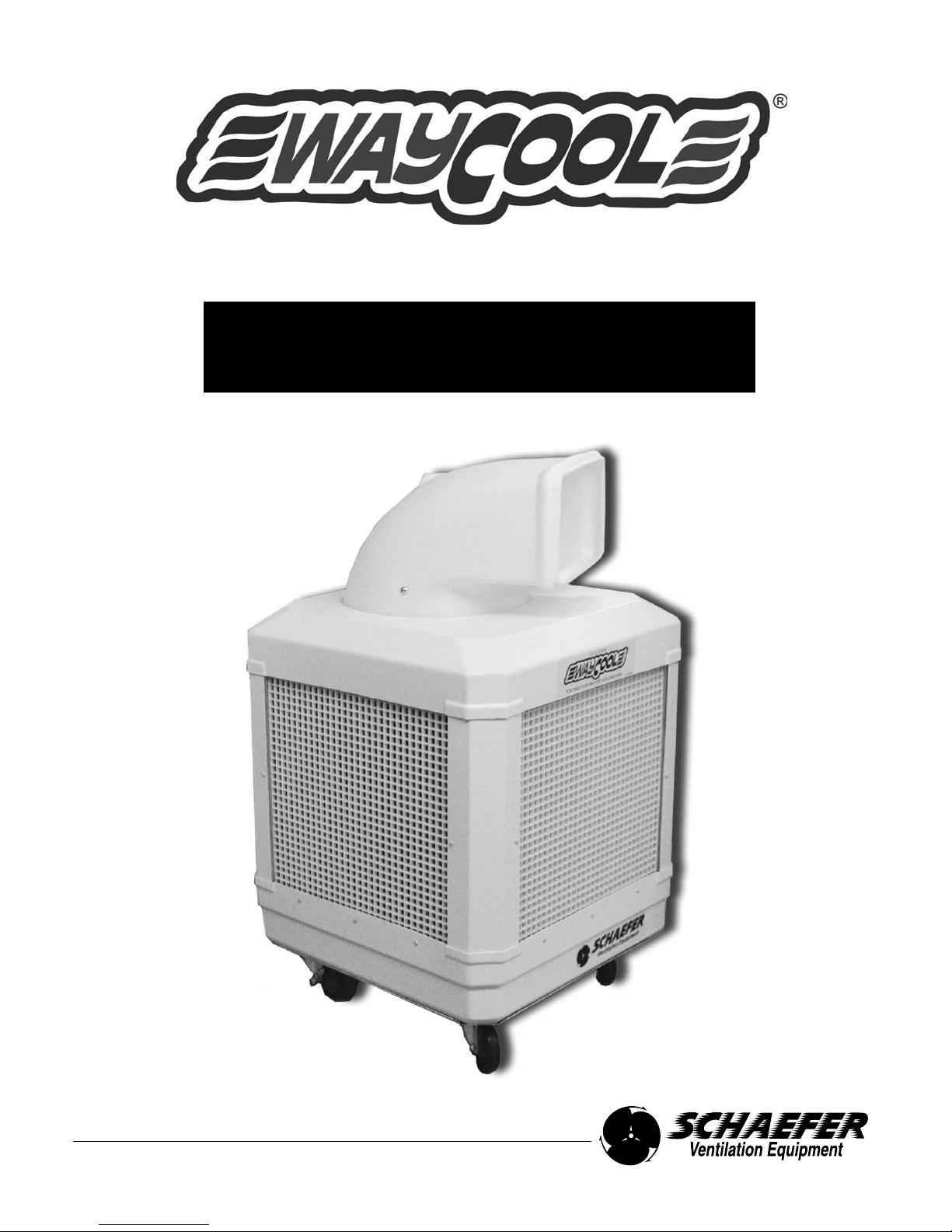
Portable Evaporative Cooler
WayCool®1/3HP - Series
USER'S MANUAL
Page 2

INTRODUCTION ..................................................................................................................................................................1
Why Use Evaporative Coolers in your Work Place? ............................................................................................................1
How Evaporative Cooling Works? ........................................................................................................................................1
ABOUT THIS MANUAL........................................................................................................................................................2
SAFETY INFORMATION ....................................................................................................................................................2
SAFETY RECOMMENDATIONS..........................................................................................................................................3
WC-1/3HP SPECIFICATIONS ............................................................................................................................................4
WC-1/3HP UNIT DESCRIPTION ..........................................................................................................................................5
WATER SUPPLY SYSTEM................................................................................................................................................6-7
COOLING PAD ASSEMBLY ................................................................................................................................................8
BLOWER AND DUCTWORK ..............................................................................................................................................9
CONTROL ..........................................................................................................................................................................10
OPERATION AND MAINTENANCE ............................................................................................................................11-13
Unit Placement and Other Considerations ........................................................................................................................11
Unpacking and Initial Setup ................................................................................................................................................12
Regular Cleaning ................................................................................................................................................................13
Normal Startup ....................................................................................................................................................................13
Normal Shutdown ..............................................................................................................................................................13
TROUBLESHOOTING ........................................................................................................................................................14
Cooling Pads not Wetting ..................................................................................................................................................14
Foaming ............................................................................................................................................................................14
Line Clogs or Obstructions ................................................................................................................................................14
Splattering out Front ..........................................................................................................................................................14
Leaking out Bottom ............................................................................................................................................................14
Odor Control........................................................................................................................................................................14
Scale Buildup ....................................................................................................................................................................14
Unit Does Not Oscillate ......................................................................................................................................................16
Blower Duct Appears to Jump while Oscillating ................................................................................................................16
Excessive Noise ................................................................................................................................................................16
Blower Duct Lifts up Out of Recess in Top of Unit..............................................................................................................17
Automatic Shut Off Kit Not Shutting Off ..............................................................................................................................17
Automatic Shut Off Kit Shutting Off Too Soon ..................................................................................................................17
OPTIONAL ACCESSORIES ..............................................................................................................................................15
Pneumatic Wheel Option ..................................................................................................................................................15
Water Conditioner ..............................................................................................................................................................15
Cleaner ................................................................................................................................................................................15
Oscillating WayCool
®
..........................................................................................................................................................16
Automatic Shutoff Option ..................................................................................................................................................17
General................................................................................................................................................................................18
Warranty ............................................................................................................................................................................19
Table of Contents
Page 3
Introduction
WHY USE EVAPORATIVE COOLERS IN YOUR WORKPLACE?
• The WayCool®evaporative cooler requires little space, has a low initial cost, is inexpensive and simple to operate and requires
minimal scheduled maintenance.
• Due to the design and construction of the cooling pads, cooling efficiency is normally maintained near optimum throughout the life
of the pads. (Approximately two seasons)
• In many cases, evaporative coolers are a better solution than mechanical refrigeration systems because they are more economical
to operate and maintain and do not use environmentally sensitive and costly refrigerants.
HOW EVAPORATIVE COOLING WORKS
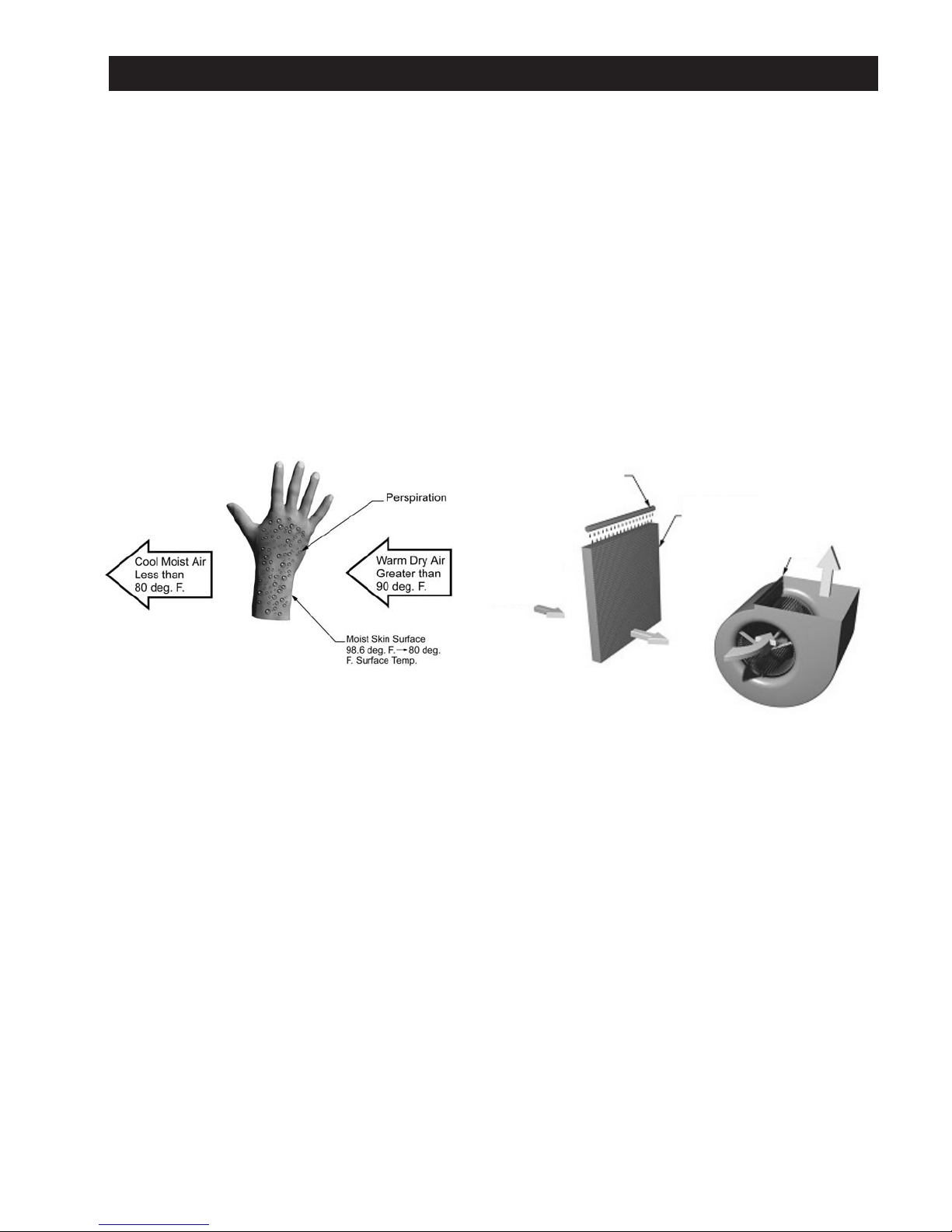
Figure WC-1HP.02 - Evaporative Cooling Principle
Evaporative cooling is the same process your body uses to cool itself. When you perspire, and air moves across your skin, a portion of the
perspiration (water) evaporates. Evaporation requires heat to change liquid water-to-water vapor and this heat is taken from your skin,
producing the cooling effect.
In an evaporative cooler, the cellulose cooling pads take the place of your skin, water instead of perspiration wets them and a fan moves the
air. The air blows across the cooling pads and evaporates moisture. Heat is drawn from the pads and the air, dropping the air temperature
and producing the cooling effect. The cooled air is then forced through a building or space and displaces the warm air out building openings,
cooling the surroundings. In addition, air velocity increases the cooling effect as it moves over the skin of people in the airflow path.
WayCool
®
evaporative coolers are portable and use the latest technology to provide large volumes of cool air, efficiently and inexpensively
for cooling small to medium size areas. Simply adding more units can accommodate larger areas. With proper sizing and application, a
WayCool®portable evaporative cooler can lower the effective air temperature by up to 20°. Even in high humidity, the efficiency of the
WayCool®evaporative cooler provides effective cooling.
1
Cool moist air
less than 80
degrees F.
Warm dry air
greater than 90
degrees F.
Pipe dripping
water onto
pads.
Wetted cellulose
pads
Fan
Page 4
About this Manual
The intent of this manual is to help you in two ways: to provide you with step-by-step instructions for quick and easy assembly of your
product and to serve as a reference for simple maintenance and questions regarding your product.
Important! Read ALL instructions carefully before starting your WayCool
®
.
• Optional equipment contains necessary instructions for assembly or operation.
Important! Pay particular attention to all SAFETY information.
Important! The WayCool
®
Evaporative Cooler is labeled with a serial number. The serial number is located inside the unit on
the aluminum frame, behind the switch. Note: Removal of the serial number label will void all warranties.
All information, illustrations and specifications in this manual are based on the latest product information available at the time of printing.
We reserve the right to make changes at any time without notice.
Warning and Danger Decals have been placed on the equipment to warn of potentially dangerous situations. Care should be taken to
keep this information intact and easy to read at all times. Replace missing or damaged safety decals immediately.
Using the equipment for purposes other than specified in this manual may cause personal injury and/or damage to the equipment.
Safety-Alert Symbol
This is a safety-alert symbol. When you see this symbol on your equipment, be alert to the potential for personal injury.
This equipment is designed to be installed and operated as safely as possible… however, hazards do exist.
Signal words are used in conjunction with the safety-alert symbol to identify the severity of the warning.
CAUTION indicates an imminently hazardous situation, which, if not avoided, COULD cause damage to your equipment or equipment
failure.
WARNING indicates a potentially hazardous situation, which, if not avoided, COULD result in death or serious injury.
Safety Information
2
Page 5
Safety Information
Safety Recommendations
Follow Safety Instructions
Carefully read all safety messages in this manual and on your equipment safety decals. Follow recommended precautions and safe
operating practices.
Keep safety decals in good condition. Replace missing or damaged safety decals.
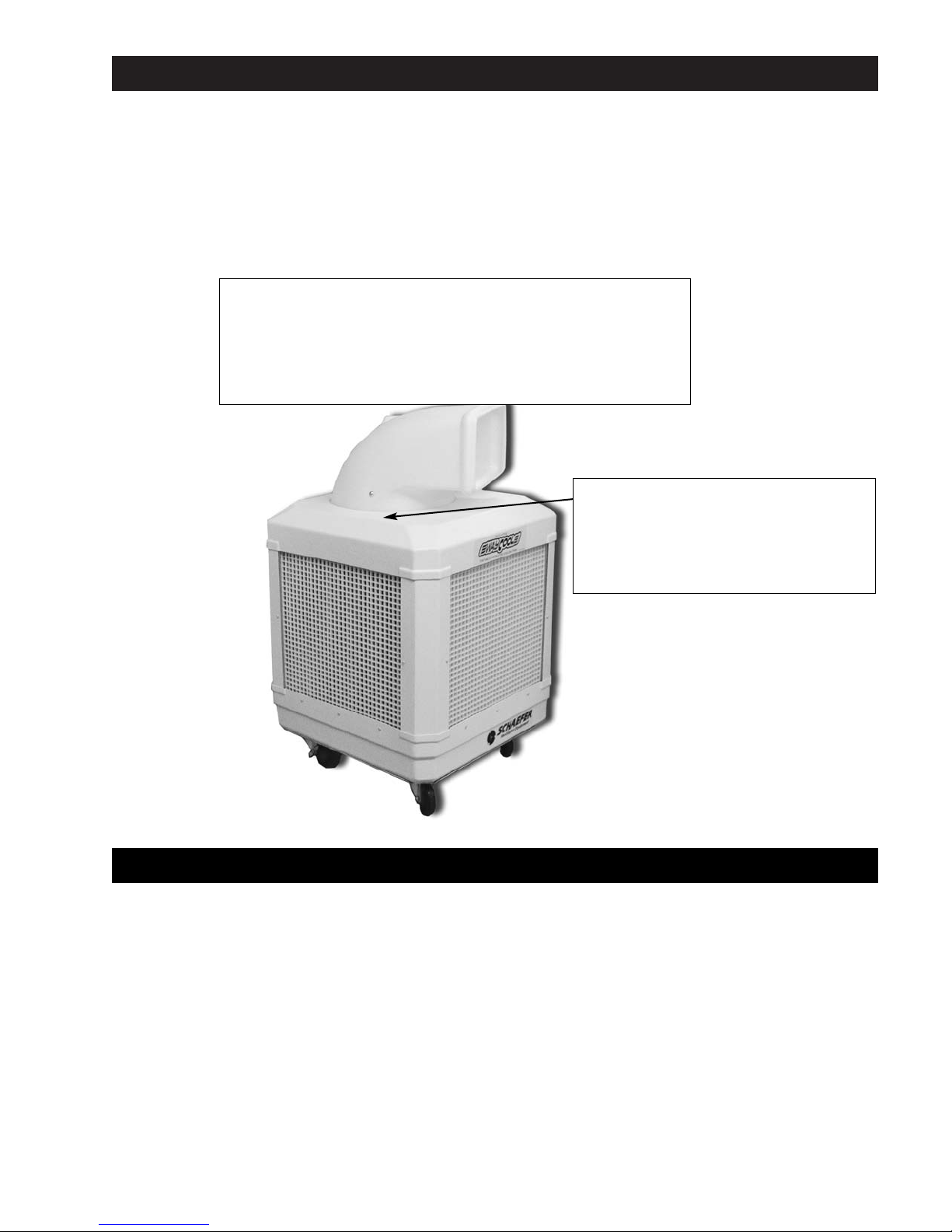
Decal Descriptions
This diagram shows the proper location of the safety decals as shipped from the factory. Replace damaged or missing decals. Make sure
the decals are easy to see at all times.
READ AND SAVE THESE INSTRUCTIONS!
• This is an electric device with moving components. There is the possibility of fire, electric shock, or injury to persons. Ensure all the
safety recommendations are adhered to in order to minimize this risk.
• Disconnect all power and unplug the unit before you inspect, clean or perform maintenance on the components of the unit.
• Never reach into the unit when it is running; you could become entrapped by the v-belt or injured by the rotating fan blades.
• The metal frame edges are sharp; don't run your hand along them. Be careful and wear gloves when you reach under the frame to
inspect the PVC pipes and mesh socks.
• A GFCI (Ground Fault Circuit Interrupter) is recommended for use with this product.
• If pads and grates are removed for servicing, they must be replaced prior to operating unit.
3
Start Unit -Turn Water pump on 5-10 minutes
before running blower. To wet evaporative cooling
pads.
Shut Down -Turn Pump off and run only blower until
evaporative cooling pads are dry. This prolongs the
life of the pads.
WARRANTY- VOID IF YOU RUN THE PUMP
WITHOUT WATER.
CAUTION - ALWAYS TURN OFF AT SWITCH AND
DISCONNECT POWER BEFORE REMOVING
EVAPORATIVE COOLING PADS FOR CLEANING
OR INTERNAL MAINTENANCE.
CLEANING- Clean pads a minimum of once every
two weeks. Remove pads from unit and clean with
garden hose only - DO NOT use chemicals or high
pressure hose.
This decal is found on the top
of the unit, same side as the
water fill adapter.
Actual WC-1/3HP
WayCool
®
varies slightly
from unit shown here.
This warning decal is found on the top of
oscillating units only.
WARNING!
Interference with the oscillating spout while the unit
is operating, or manually directing the oscillating
spout, will cause damage to the gear motor. Keep
oscillating path clear of obstructions.
Figure WC-1/3HP.03 - Decals
Page 6
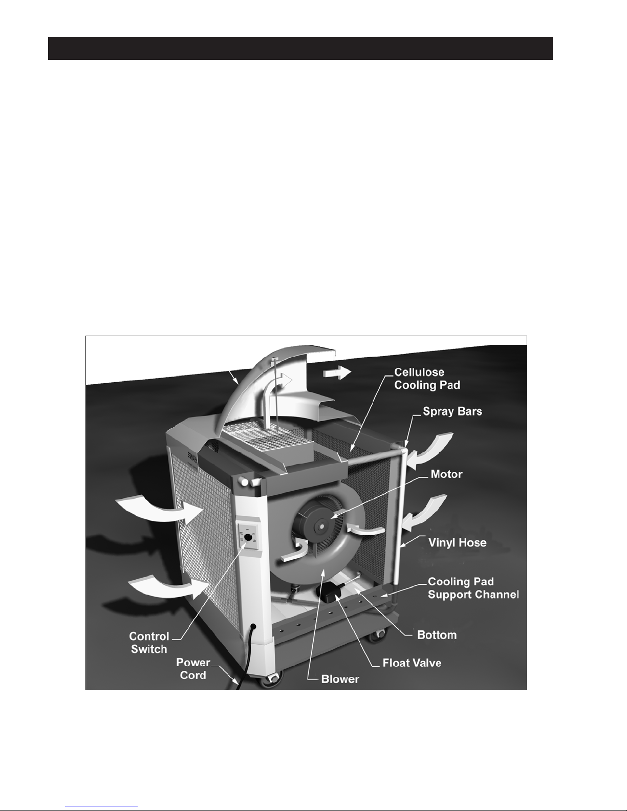
WC-1/3HP Specifications
• Height and Width - 25" X 12" Wide X 42" High (With Casters and Directional Blower Duct)
• Shipping Weight - 130 Pounds
• Blower - Double-Inlet Centrifugal
• Motor - 1/3 HP, 115V 2 speed, 60 HZ (also available in 230V and 50 HZ)
• Pump - Submersible Pump, Vane Type, 210 GPH (Gallons Per Hour)
• Pump Filter - Washable Polyethylene Filter
• Pump Discharge Filter - 480 Micron Stainless Steel
• Reservoir Capacity - 14 Gallons
• Optional Water Supply - Standard ¾" Hose Connection (Garden Hose Size)
• Housing - High Impact ABS Plastic w/UV Protection
• Evaporation Media - Chemically Treated Cellulose Paper
Figure WC-1/3HP-04.WayCool®Evaporative Cooler Overview
4
Actual WC-1/3HP WayCool
®
Varies slightly from unit shown here.
Page 7

WC-1/3HP Unit Description
The WayCool®evaporative cooler is a completely self-contained, portable unit capable of delivering 25.5 MPH velocity of air with a
temperature drop of up to 20°. The unit is composed of:
• Level-controlled water supply system
• Cooling pad assembly
• Motor-driven blower and ductwork
• Controls
• Frame and housing
The bottom is made of high impact ABS plastic and holds approximately 14 gallons at normal operating level (about 4" deep).
A float-operated valve automatically maintains proper water level when the unit is connected to a water supply.
The bottom rests on, and is fixed to, an aluminum cradle. The bottom, in turn, is secured to the aluminum frame. Four casters (2 locking, 2
non-locking) are attached to the underside of the aluminum cradle.
A pump draws water from the bottom and discharges it through the vinyl hose to the PVC pipes located above the cooling pads. The PVC
pipes distribute water onto the top of the cooling pads; saturating them. Excess water drips back into the bottom through the holes in the
cooling pad support channels.
The cellulose cooling pads sit in support channels and are held in place by plastic retaining grates. The grates also help prevent damage to
the cooling pads. Two pad sections fit in each side of the unit (total eight sections) to totally enclose the unit.
The blower is hung from the top of the frame and powered by a direct drive 1/3HP electric motor. The blower draws room air through the
cooling pads where it picks up moisture and cools by evaporation. The blower then discharges the cooled air.
Note: It is important the cooled space has sufficient air openings so the warmer air can flow out and be replaced by the cooled air.
A closed-in space or high humidity will reduce the cooling effect. See Unit Placement and Other Considerations in the "Operations
and Maintenance" section of this manual.
A screen covers the discharge duct to prevent foreign objects from entering the blower. A threaded rod screws through a threaded brace
above the screen to hold the blower duct in position. A plastic knob secures the blower duct to the rod. The blower duct is made of a tough,
durable plastic and can be manually rotated 360 degrees to provide cool air in any direction without moving the unit.
Note: Water weighs about eight pounds per gallon, so when the unit is full, it weighs over 240 pounds. During setup and before
startup, place the unit in the desired location and then fill the bottom. Do not attempt to lift the unit once it is filled and be careful
to avoid spills when moving it; even over smooth ground. Do not try to push it over rough or soft ground as you can overstress
the wheels and frame and cause structural and component damage, which is not covered by warranty.
5
Page 8
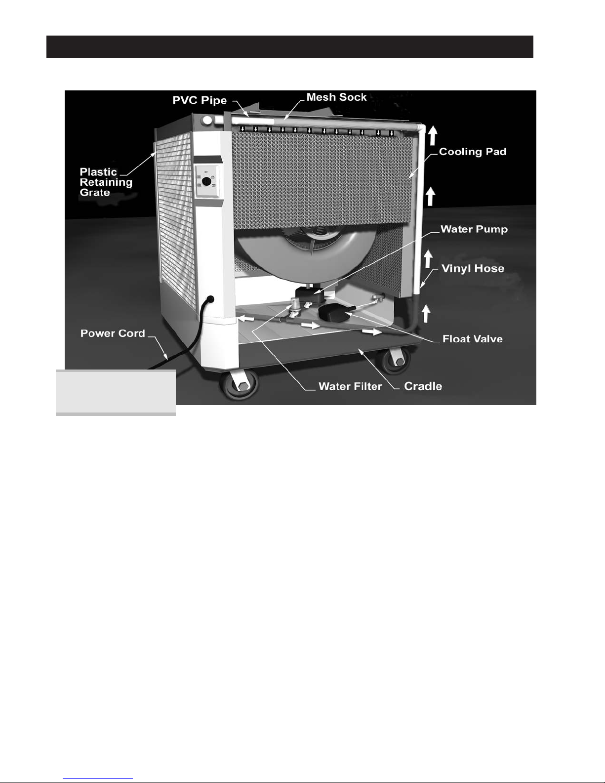
Water Supply System
Actual WC-1HP
WayCool
®
varies slightly
from unit shown here.
The bottom can be supplied continuously with an ordinary garden hose by attaching the supplied hose adapter (see Figure WC-1/3HP.07)
to the fill connection, or it can be filled manually.
With a continuous water supply connected, the float valve in the bottom (like the one in your toilet tank) rises and falls with the water
level. A linkage attaches the float to the shutoff valve in the fill connection. As the water level rises to normal operating level (about 3"
deep), the float valve shuts off the water supply. When the water level drops, the float valve reopens to maintain a normal operating level.
After unplugging the unit, the bottom can also be manually filled with a hose or bucket; if a hose connection is impractical. Simply remove
any of the plastic retaining grates and one of the cooling pad sections and place the hose, or pour the water, directly into the bottom.
When you fill the bottom manually it can be filled to a higher level, but make sure someone monitors the filling operation to avoid
overfilling and flooding.
Note: Water damage due to overfilling is not covered by the warranty.
Note: When you run the unit and manually fill it, check the water level frequently so it does not run dry. Operating the pump
without water will damage it or reduce its service life. This is not covered by the warranty. The cooling effect also stops if the
pads dry.
Note: Pads and grates must be replaced before operating unit.
Figure WC-1/3HP.05 - Water Supply System
6
Actual WC-1/3HP-DHL WayCool
®
varies slightly from unit shown here.
Page 9
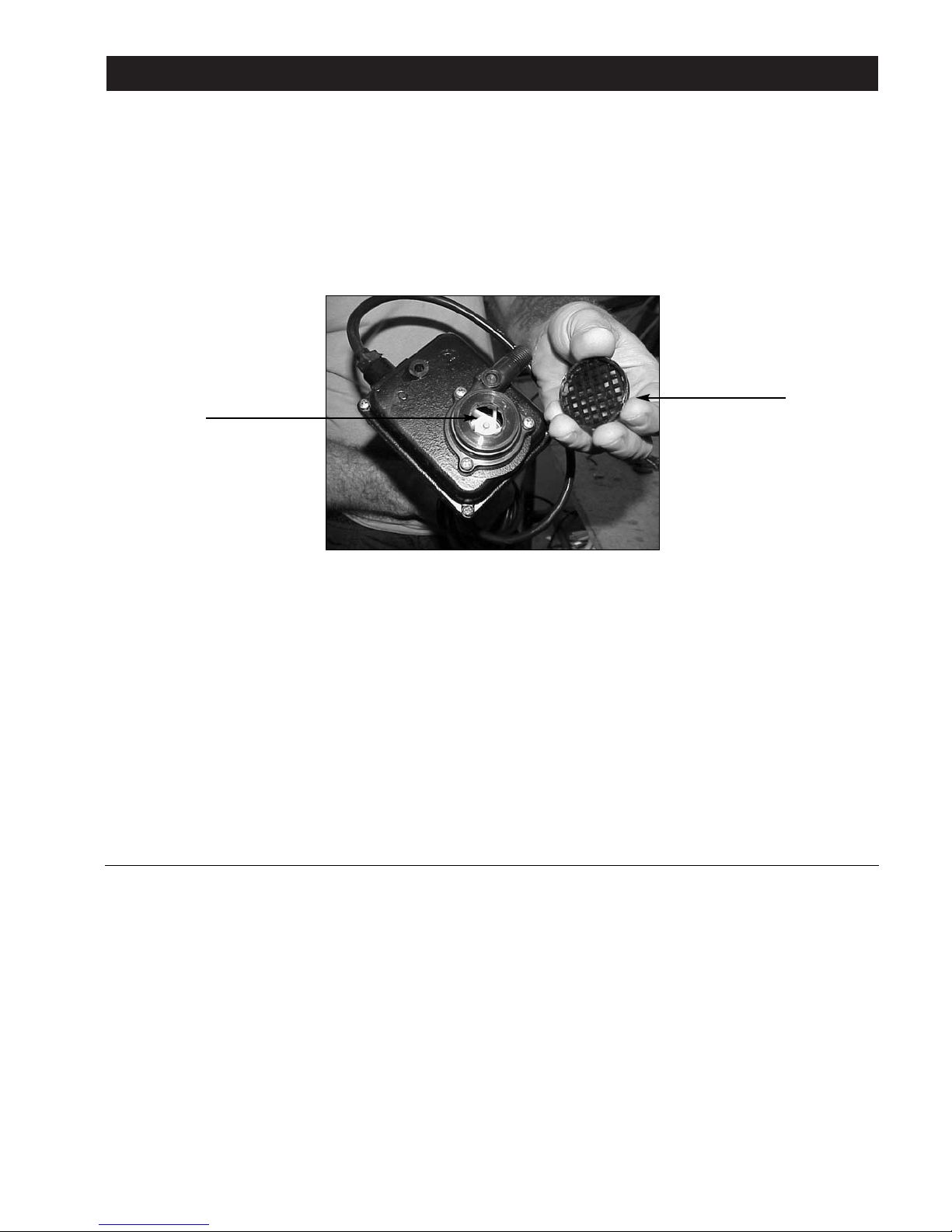
Water Supply System
A drain in the bottom allows you to drain the unit for cleaning and maintenance. A drain cap on the underside of the aluminum tray covers
the drain during operation. Make sure the cap is in place before you fill the bottom. The drain cap should be finger-tightened only.
The pump is attached to a bracket, which in turn is fixed to the blower housing. The bracket holds the pump in its proper position on top of
the foam filter and slightly above the bottom; allowing sufficient space for water to enter the pump suction.
The pump can be easily removed and replaced with the services of a qualified electrician.
A small plastic screen covers the pump inlet to prevent foreign matter from entering and damaging the pump impeller. The screen snaps
in place and can be easily removed for inspection or cleaning.
The pump sits on a foam filter; somewhat like a sponge. The filter traps dirt that could enter the water distribution system and build up on
the cooling pads; reducing their effectiveness. Dirt could also accumulate in the PVC pipes and plug up the spray holes.
The pump discharges through a fine, washable screen filter which decreases the contamination of the cooling pads and water system.
The discharge filter casing is a clear plastic so dirt buildup on the internal screen is easily visible. As dirt builds up, water flow to the
cooling pads is reduced and performance decreases. The clear filter housing is threaded and screws into the filter body for easy removal
to access the screen.
Note: A dirty water supply will quickly reduce the unit's performance and the unit will require more frequent cleaning to maintain
cooling effectiveness. Always try to use a filtered, treated water supply.
A clear vinyl hose connects the pump to the filter. From the filter, a "T" connector supplies two lines that run along the bottom and up
opposite frame corners to supply the PVC pipe with water. Each vinyl hose connects to two PVC pipes, which run horizontally along the
top of the frame above the cooling pads.
The PVC pipes have a series of holes that run the full length of the pipe. Each PVC pipe is covered with a plastic mesh sock which helps
break up the water as it leaves the spray holes. This gives a more even water distribution across the cooling pad and reduces splashing.
The holes direct the water inward at a 90° angle to continuously saturate the cooling pads from the top down. Excess water drains back to
the bottom through drainage holes in the bottom support channels which support the cooling pads.
Note: Water cleanliness has a major effect on the cooler's performance. Use a clean water supply and consider a water softener
if your water is hard. Dissolved solids in hard water deposit on the cooling pad surfaces and reduce the airflow through the unit
and therefore the amount of evaporation.
Figure WC-1/3HP.06 - Pump
Pump Impeller
Plasitc Screen
7
Page 10

Cooling Pad Assembly
The cooling pads are critical for proper, efficient cooler operation. They are made of laminated cellulose (paper) fibers and arranged to
give a large surface area for evaporation and to provide a rigid structure. The shape of the cells allows high velocity airflow through the
pad at a minimum pressure drop. At the same time, the air passages between the cells force the incoming air to impinge on the wet cell
surfaces and maximize evaporation.
Note: The WayCool® evaporative cooler also acts as an air filter and removes dust and other particles from the air. This dirt
collects on the cooling pads and lowers cooler efficiency. The pads should be cleaned at least weekly and more frequently in
dusty conditions. See Regular Cleaning under "Operation & Maintenance".
The pump supplies a continuous flow of water over the pads causing a "sheet flow" which constantly replaces the water lost to
evaporation and keeps the pads saturated.
One cubic foot of the cooling pad material holds about a gallon of water during operation. One cubic meter holds about 100 liters of water.
Note: The cooling pads are relatively strong but are subject to crushing, especially when wet. Always run the unit with the
plastic retaining grates in place and handle them carefully when you clean them. Crushed cells reduce the total airflow through
the unit and therefore lowers it's cooling capacity.
The cooling pad sections, two sections for each side (eight sections total), sit in metal channels at the top and bottom of the unit. The
channels hold the cooling pads in position and form four sidewalls to completely enclose the unit.
The top channels house the PVC pipe, which run horizontally along the channel directly above the cooling pads. The bottom channels
have a series of holes drilled through them to allow excess water flowing down the cooling pads to return to the bottom.
The plastic retaining grates fit in front of the cooling pads and sit in the same channels as the pads; holding them in place and protecting
them from accidental damage. The plastic grates and cooling pads are easily
removed by placing a flat blade under the bottom and lifting upwards, then outwards. Once one pad is removed, the others can be lifted
up and out by hand without using a blade.
Note: Do not remove or handle the cooling pads when they are wet, as they damage easily. Run the blower without the pump
until pads are dry. With normal care, the pads should last at least two seasons. Abuse or mishandling will reduce their
effectiveness and shorten their life.
8
Page 11
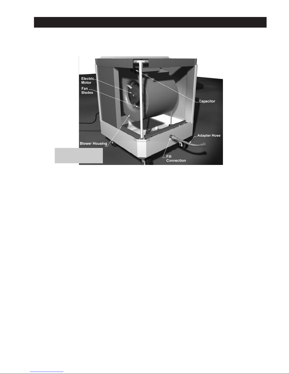
Blower and Ductwork
The WayCool® WC-1/3HP uses a direct drive, 1/3 HP electric motor to drive a centrifugal blower. The blower draws room air through the
cooling pads and discharges the cooler air through the blower duct, displacing the warmer air with cooler air and decreasing the
temperature.
The blower is secured to the top of the frame and hangs upside down to direct the air out the top of the unit. Brackets on each side of the
blower casing secure the blower to the frame and hold it in position.
The electric motor is secured to the blower casing by metal braces and directly connects to the blower shaft. A startup capacitor is
attached tot the top of the blower casing and is wired to the motor.
Note: A capacitor retains electrical energy even after the unit is shut down and unplugged. DO NOT TOUCH the bare
connections or you could be injured.
The power cord runs down the frame leg that has the control switch on the outside. It exits the frame leg at the bottom and has a male
plug that must be plugged into a normal, 120-volt outlet. The cord is approximately seven feet long.
Note: The WC-1/3HP unit requires 120 volts and 5 amps of power. This is normally available on most circuits. However, if you
are running a number of other items on the same circuit, you may trip the breaker. If so, plug the WayCool® into another
circuit. If you require an extension cord, make sure it is at least #14 wire and no longer than 50 feet. If you need a longer cord,
use one with # 12 wire. Using smaller wire or a longer cord will degrade the WayCools®'s performance, shorten the life of the
electric motor and could cause a fire. None of this is covered by warranty.
A GFCI (Ground Fault Circuit Interrupter) is recommended for use near water.
Figure WC-1HP-DHL.07 - Fan Blower
Actual WC-1HP-DHL
WayCool®varies slightly
from unit shown here.
9
Page 12
Controls
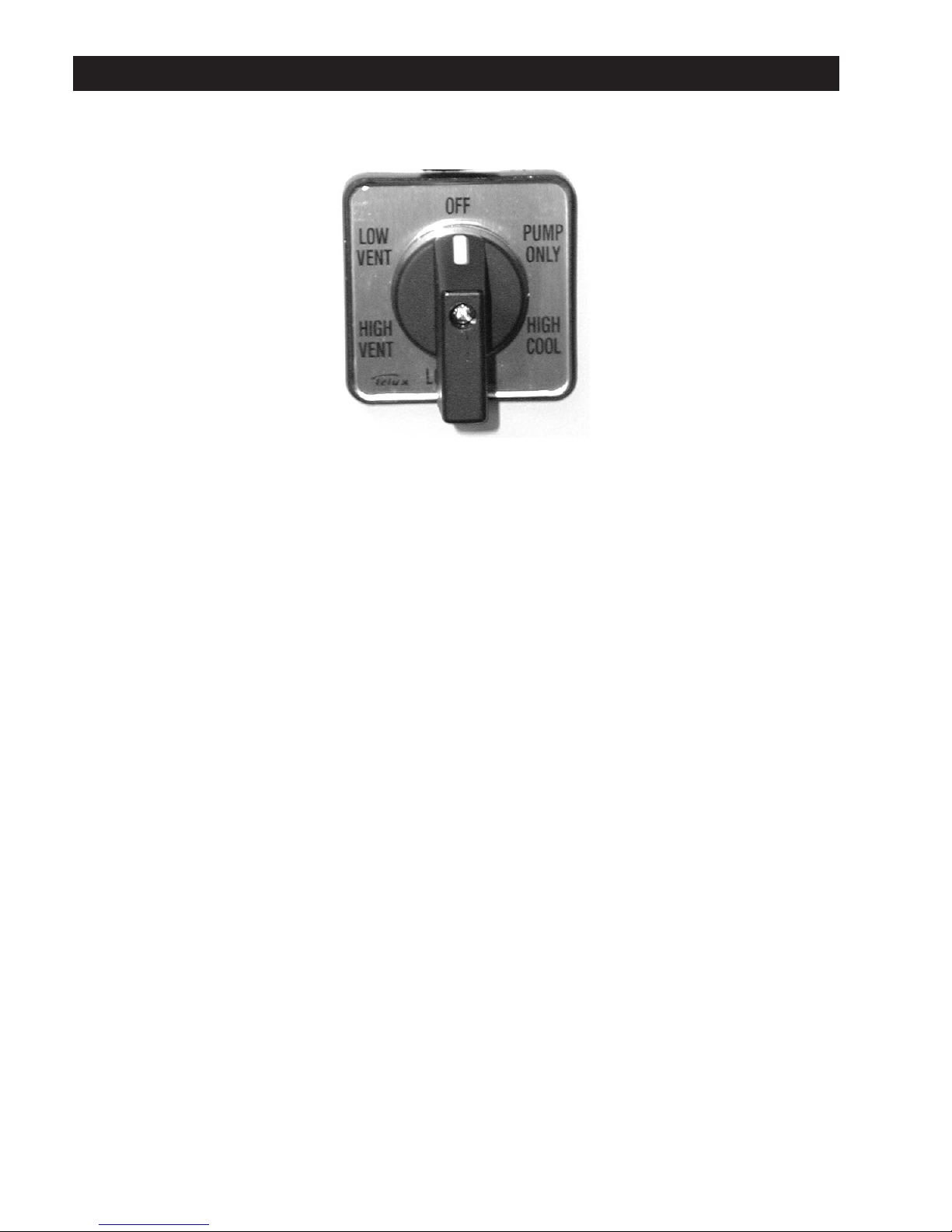
The WayCool®WC-1/3HP control switch is mounted on the outside of one frame leg (see cover fig).
It has the following positions:
OFF - Power is off to the blower motor and the pump motor.
LOW VENT - The blower runs at low speed and the pump is OFF.
HIGH VENT - The blower runs at high speed and the pump is OFF. Use this setting to quickly dry the cooling pads for removal and
cleaning.
LOW COOL - The blower runs at low speed and the pump is on. Use this setting for low cooling loads.
HIGH COOL - The blower runs at high speed and the pump is on. Use this setting for maximum cooling.
PUMP ONLY - Pump is on and the blower is OFF. Use this setting during startup to first saturate the cooling pads, then switch to LOW
COOL or HIGH COOL to begin cooling.
Figure WC-1/3HP.08 - WayCool®Control Switch
10
Page 13
Operation & Maintenance
Unit placement and other considerations
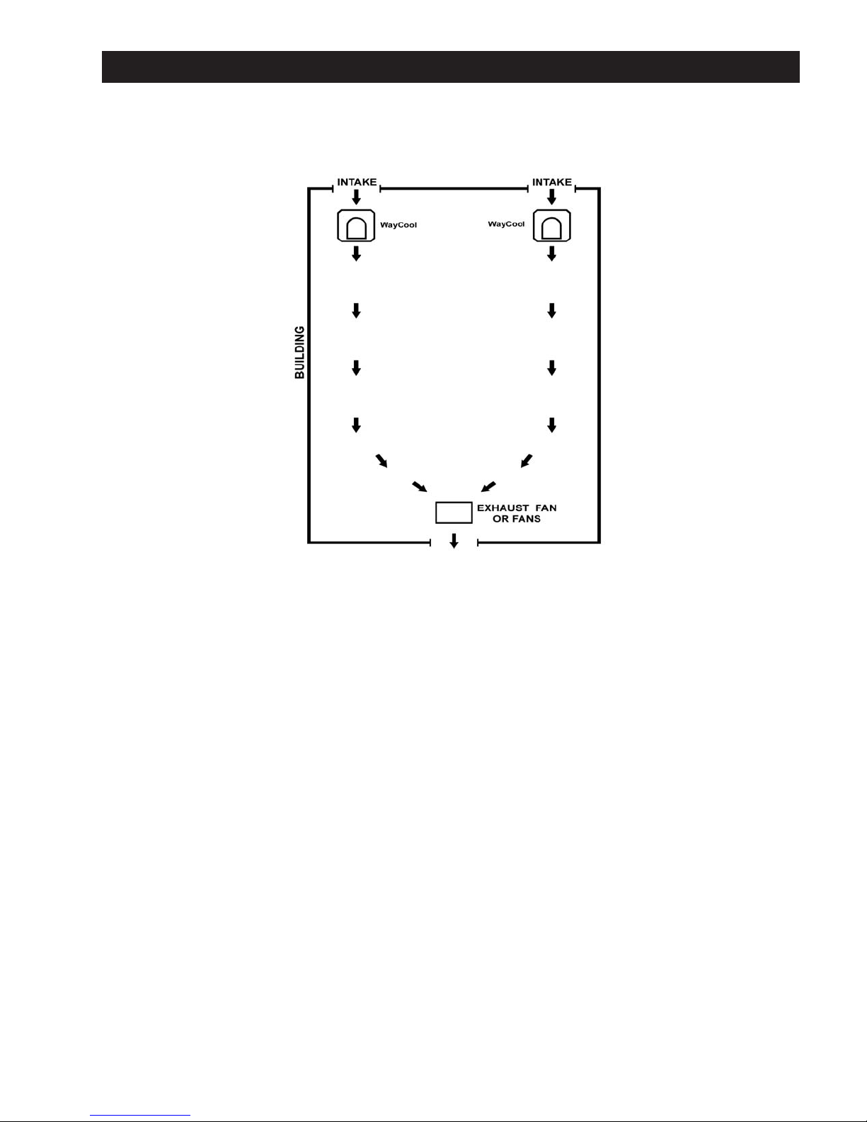
The WayCool®unit(s) should be placed at one end of the building and an appropriate exhaust fan should be at the
opposite end to pull the cool air from the WayCool® unit and discharge the warm air out of the building.
Try to get all the air flowing in the same direction. Do not direct other fans against the WayCool®unit. It will counter the
WayCool
®
's airflow and stop the cooling effect.
Obstructing the airflow from the WayCool®unit severely reduces the cooling effect.
Avoid using ceiling fans as they disrupt the airflow from the WayCool
®
unit.
Use as many exhaust fans as possible to create a natural draft through the building. This will enhance the WayCool®'s
performance.
Figure WC-1/3HP.09 Typical WayCool®Unit Arrangement
11
Page 14
Operation & Maintenance
UNPACKING AND INITIAL SETUP
The WayCool®WC-1/3HP Evaporative Cooler is shipped upright in a corrugated container. The WayCool®WC-1/3HP is fully assembled
and ready for service except for thoroughly cleaning manufacturing dust from the cooling pads before running it for the first time.
CAUTION: Be careful when you move the unit while it is in the shipping container and when moving it around with the
container removed. Avoid jarring or dropping the unit to prevent damage to the bottom.
1. With the unit in the upright position as marked on the container, use a sharp knife or scissors to cut the banding material on the
shipping container.
Note: Do not discard the shipping container until you have thoroughly inspected the unit.
2. Remove the shipping container.
3. Inspect the entire unit for shipping damage.
4. Ensure the switch is OFF and the unit is unplugged.
5. Remove the plastic retaining grates from all four sides of the unit. Use your fingers to lift each upward,
then outward from the bottom.
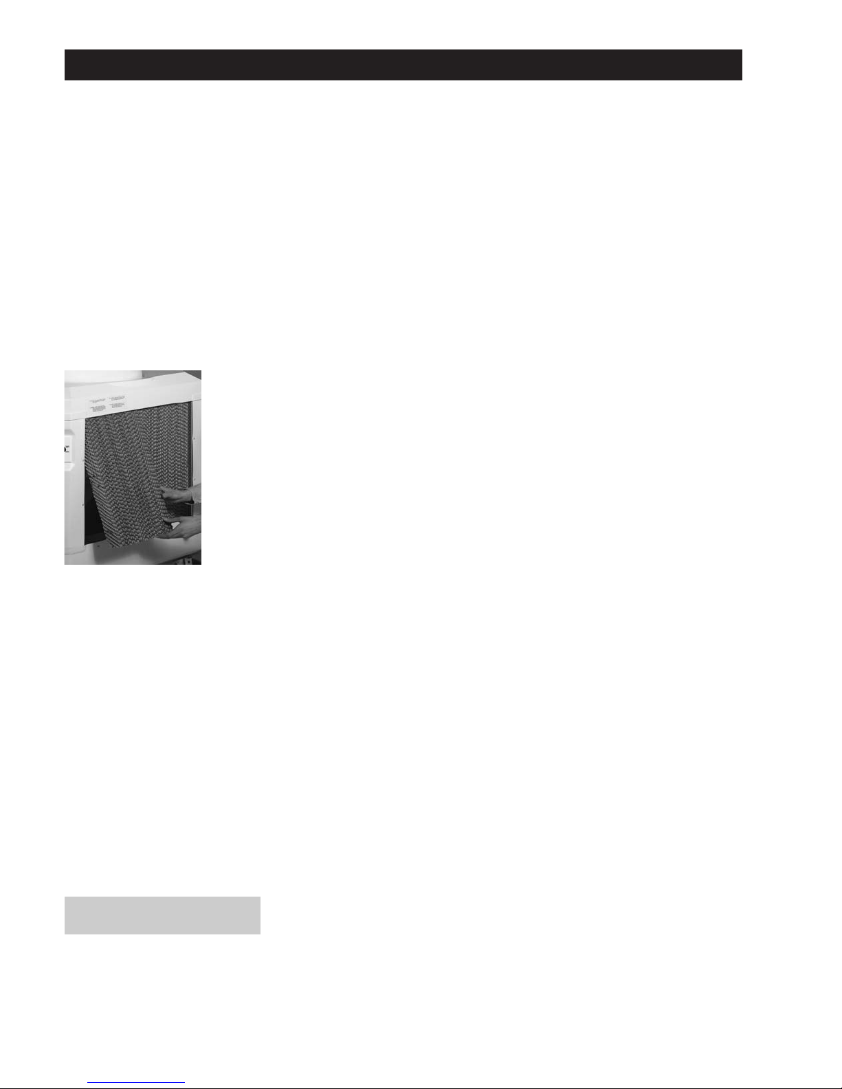
6. Remove the cooling pads from all four sides of the unit. Place a putty knife or large, flat-bladed
screwdriver under the pad to lift it up, then outward. With one pad out, the rest can be easily removed by
placing one hand on the pad's inside, your other hand on the outside and lifting the pad up and out from
the bottom (see figure WC-1/3HP.10).
7. Remove Cardboard from blower.
8. Look for cracks on the inside four bottom corners of the unit. This is also an indication of rough
handling.
9. Ensure the frame legs are straight and in alignment, and that the blower is sitting level and in proper
position.
Note: If you notice any damage to your unit, immediately contact the dealer where you purchased it.
10. Clean thoroughly all eight cooling pad sections using a garden hose.
Note: The unit should only be cleaned with approved cleaners or clean water only. Refer to page 15 for approved cleaners.
11. Remove the drain cap from the underside of the bottom and rinse with a hose to flush any manufacturing dust, etc. from the unit.
Replace the drain cap.
12. Replace the pads and the protective retaining grates.
13. Proceed to "Normal Startup".
Figure WC-1/3HP.10
Actual WC-1HP WayCool®varies slightly
from unit shown here.
12
Page 15

Operation & Maintenance
REGULAR CLEANING
The frequency with which the WayCool®is cleaned will depend on the environment in which it is used. The more dirty the environment the
more often it will need cleaning. In most cases the WayCool
®
will need to be cleaned weekly.
Caution: The pads should be dry before you handle them, as they are stronger when dry than when they are wet and less
susceptible to damage. If they are wet, run the unit in the HIGH VENT position until they are dry. After cleaning, let the pads air
dry before you replace them.
1. Turn the switch to OFF and unplug the unit.
2. Remove the plastic retaining grates and check the pads for cleanliness. If they are dirty, remove and clean by spraying with a
garden hose, water only. If they are not dirty you will still need to remove the cooling pads to clean the inside of the unit. Dirty
cooling pads reduce the unit's effectiveness.
3. Use a garden hose to rinse out the bottom and the inside of the unit. The dirt that accumulates is removed from the air during
operation, as the WayCool
®
unit also acts as an air filter.
4. Remove the drain cap from the underside of the unit and let the unit drain completely. Rinse out any remaining dirt.
5. Replace the drain cap (finger tighten only).
6. Remove the pump discharge filter by unscrewing the top, removing the screen and rinsing it with a hose or under a tap. Replace the
filter screen and screw the top back on.
7. Remove the pump filter from underneath the pump. Wash thoroughly with a hose. Compress filter and place back under the pump.
8. Replace the cooling pads once they are dry and reinstall the plastic retaining grates.
Note: With proper use and regular cleaning, the cooling pads will last about two seasons. If you handle them wet and are
abusive, however, they will be easily damaged. Refer to page 15 for recommended conditioning and cleaning chemicals.
NORMAL STARTUP
1. Place the unit in the position where it will be run. Do not attempt to lift or move the unit once it is filled. Damage to the unit or a large
spill may occur.
Note: When you decide where to place the unit, make sure there are no obstructions in the way that will disrupt or block the
airflow. Make sure the unit is level at all times. Keep the unit at least three feet away from walls or other obstructions that will
interfere with airflow into the unit.
2. Check to ensure the drain cap is in place and secure.
3. Connect the garden hose to the brass hose adapter. Check that there is a washer in the hose connection's female end.
4. Open the water supply valve and check that water enters the bottom through the float valve by removing one cooling pad on the
side with the water connection. Allow the unit to fill and check that the float valve completely shuts off the water.
5. If you are manually filling, remove one or more cooling pads and fill the bottom with a bucket or hose.
6. Visually monitor the filling operation to avoid overflowing and causing spill damage.
7. Plug the unit into an outlet.
8. Adjust the blower duct to discharge the cool air in the desired direction and tighten the knob on the end of the threaded rod.
9. Turn the switch to the pump only position and let it run for 5 - 10 minutes to saturate the cooling pads. Check that the pads are
saturated completely and there are no dry spots.
CAUTION: Do not run the pump without water in the bottom or you will damage the pump. Running the pump dry will void the
warranty on the pump.
10. Turn the switch to the High Cool or the Low Cool position to begin normal cooling operation.
NORMAL SHUTDOWN
1. Turn the switch to the High Vent position, and let the unit run until the cooling pads are dry. This will maximize the life of the pads.
2. Turn the switch to the OFF position. Unplug the unit if you are going to clean the pads or inspect the components.
3. Shut off the water supply.
4. Drain the bottom if you are going to clean it or store it.
5. If the unit will be stored for the season, ensure the cooling pads are completely dry, and then remove them. Wrap them in plastic
bags or store them in a clean place where they will not be damaged or get dirty. The unit should be cleaned thoroughly before
storing.
13
Page 16

Troubleshooting
COOLING PADS NOT WETTING
1. Ensure that the bottom has water.
2. Ensure that the motor switch is in the start position and the pump switch is in the on position.
3. Ensure that the pump is running.
4. Pump is running but no water:
a. Ensure hose is connected.
b. Inspect and clean the pump discharge filter.
c. Inspect and clean the pump intake filter.
d. Ensure the impeller on the inside of the pump turns freely - see figure WC-1HP.05 - Pump.
5. Pump is not running:
a. A certified electrician must check wiring from pump to pump selector switch.
b. If the wiring is correct, replace the pump.
FOAMING
Foaming is generally caused by a dirty water supply or contaminated water in the bottom.
1. If foaming occurs, stop the unit, drain it and flush the bottom and insides thoroughly with clean water.
2. Clean the pads and do not use any kind of chemical cleaners. Refer to the "Regular Cleaning" section for proper procedure for
cleaning the pads.
3. Reassemble, refill and restart.
LINE CLOGS OR OBSTRUCTIONS (Little or no water flow)
Depending on the cleanliness of the water and the amount of dirt, dust, etc. in the supply air, you may have to clean the PVC pipes from
time to time. Your own experience will dictate the frequency.
1. Turn off the unit and unplug it.
2. Remove the plastic knob from the threaded rod in the blower duct.
3. Remove the blower duct and set it aside.
4. Remove the two screws that hold on the unit's top cover.
5. Remove the top cover and set it aside.
6. Locate the four PVC pipes in the top metal channel. Each PVC pipe is secured to the "Y" connector by a single screw. Remove this
screw from all four PVC pipes.
7. Grip the opposite end of each PVC pipe with pliers and gently twist it out of its "Y" connector.
8. Remove the plastic mesh socks from the PVC pipes and clean them in warm, soapy water.
9. Direct a jet of water at the series of outlet holes in the PVC pipes to blow them clear.
10. Direct the water nozzle into the end of each pipe and blow them clear. Inspect them for cleanliness and repeat if necessary.
11. Reinstall the socks over the PVC pipes taking care not to bunch them.
12. Replace the PVC pipes taking care to ensure the water outlet holes are facing inwards at 90°. There is a mark on the PVC pipe that
indicates the position of the holes.
Note: Ensure you push the PVC pipes fully into the "Y" connectors so the retaining screws go through the connector and the
pipe to hold them in.
ODOR CONTROL
Ensure water source is of good quality and regular maintennace is being conducted. WayCool®Water Conditioner is available from the
factory. See page 15.
LIME OR SCALE BUILDUP
Ensure water source is of good quality and regular maintennace is being conducted. WayCool®Water Conditioner is available from the
factory. See page 15.
SPLATTERING
Out Front
See " Line Clogs or Obstructions".
LEAKING
Out Bottom
Check for cracks on the bottom. If a crack is found, repair it by using a WayCool®Repair Kit or replace the entire bottom.
See "Ordering Replacement Parts - page 18.
14
Page 17
Optional Accessories
Your WayCool®Evaporative cooler can be purchased with accessories/options or some of these options can be retrofitted to your
WayCool®after the initial purchase. Necessary instructions are included with all equipment purchased separate from your WayCool®.
Accessories or Options available at time of purchase only:
• Manual Fill and Water Level Gauge (1Hp model only)
• Oscillating air duct
Accessories or Options available at time of purchase or after purchase:
• Pneumatic Wheel
• Automatic Shutoff
• Conditioners & Cleaner Solutions
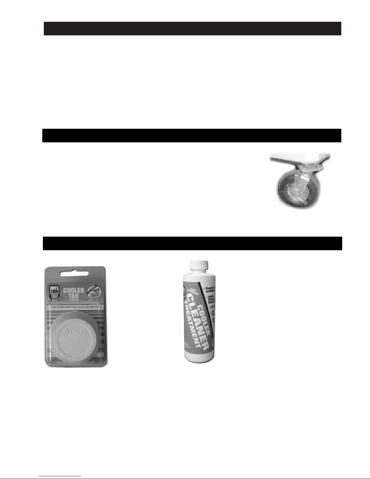
WayCool®Water Conditioner & Cleaner
Pneumatic Wheel Option
Pneumatic wheels are available at the time of your WayCool®purchase or as a retrofit kit on a
previously purchased WayCool
®
.
The pneumatic wheel options includes two locking and two non-locking wheels.
Pneumatic wheels are designed to allow for easy rolling on rough or uneven surfaces.
15
WayCool®Water
Condition is
recommended to control
odors found to be
present in some water
sources.
• Place the tab under
the float valve water
outlet for quick, fast
odor control.
• Place the tab next to
the pump for longer
lasting and more
constant odor control.
WayCool®Cleaner is recommended to remove scale
buildup from the water supply system.
• Clean WayCool
®
according to the instructions on
page 13 of this manual.
• Refill with water and add one (1) pint of Cooler
Cleaner Treatment to the water reservoir.
• Operate the WayCool®in the "pump only" mode
for approximately 20 minutes.
• Drain, clean and refill the WayCool
®
with fresh
water.
• Repeat treatment steps if deemed necessary.
• Operate WayCool
®
in normal manner and repeat
treatment when evidence of scale build up
begins.
Page 18
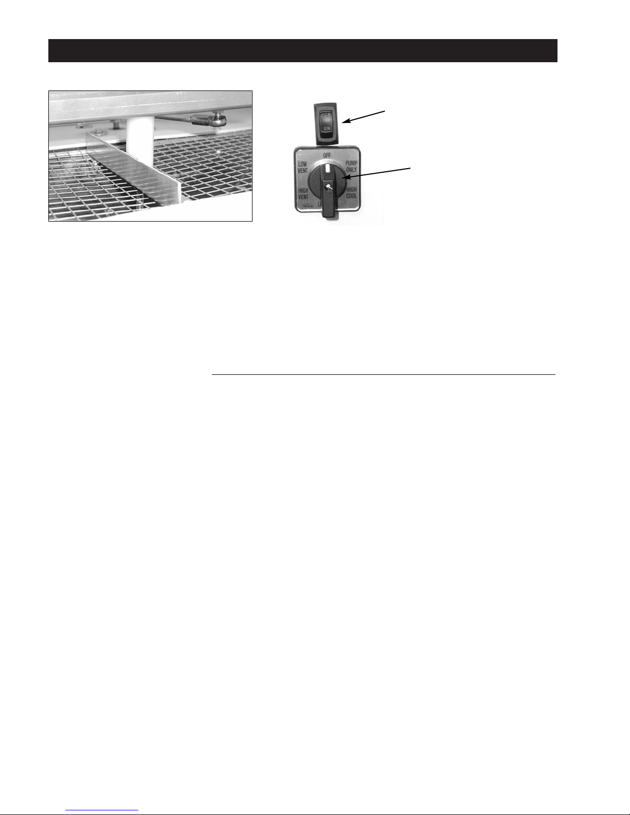
Optional Accessories
Oscillator WayCool
®
Oscillator Troubleshooting
Oscillating Assembly
The oscillator, in this WayCool®unit, is operated by a 4 RPM gear motor (WC-OSCGEARMTR) that delivers 50 in/lbs. in torque. As the
gear motor rotates, the blower duct (WC-SMBLOWERDUCT) oscillates in a 110-degree arc, which cools an area of approximately 9500
square feet.
* The design of the oscillator requires the blower duct to sit loosely on top of the unit, do not tighten it down.
• Do not place hands in blower duct (WC-SMBLOWERDUCT) while unit is operational!
• Do not attempt to stop blower duct (WC-SMBLOWERDUCT) from oscillating!
WARNING: If the top of the unit is removed for troubleshooting or any other reason, the wires from the gear motor must be first
disconnected from the oscillator switch. This can be done by first removing the (2) female disconnects that are attached to the back of
the switch.
UNIT DOES NOT OSCILLATE
1. Ensure that the unit is plugged into a standard 120-volt outlet.
2. Ensure that the oscillator switch is in the ON position.
3. Ensure that the gear motor is running. To do this, shut off the whole unit by turning the main switch to the OFF position and leave
the rocker switch for the gear motor in the ON position. You should then be able to hear the gear motor.
4. If the motor is running:
• The blower duct may be fastened too tight against the top of the WayCool
®
. The nut above the brace should be loosened allowing
1/16" clearance between the bottom of the blower duct and the top of the WayCool
®
.
• If the blower duct is not too tight, the linkage may be damaged. Look for visible damage to the linkage rod or the lever. If any of the
linkage parts are damaged, they will need to be replaced.
5. If the motor is not running, the motor may have failed or there could be a wiring problem. contact a certified electrician. If the motor
is determined to have failed, it must be replaced.
BLOWER DUCT APPEARS TO JUMP WHILE OSCILLATING
1. The blower duct may be fastened too tight against the top of the WayCool®. The nut above the brace should be loosened allowing
1/16" clearance between the bottom of the blower duct and the top of the WayCool®.
2. If the blower duct is not too tight, the linkage may be damaged. Look for visible damage to the linkage rod or the lever. If any of the
linkage parts are damaged, they will need to be replaced.
EXCESSIVE NOISE
1. The blower duct may be fastened too tight against the top of the WayCool®. The nut above the brace should be loosened allowing
1/16" clearance between the bottom of the blower duct and the top of the WayCool®.
2. If the blower duct is not too tight, the linkage may be damaged. Look for visible damage to the linkage rod or the lever. If any of the
linkage parts are damaged, they will need to be replaced.
3. A motor bearing may have failed. If the noise is determined to be coming from the motor, the bearing may have failed and the motor
may need to be replaced.
BLOWER DUCT LIFTS UP OUT OF RECESS IN TOP OF UNIT
1. The blower duct may be too loose. There should be approximately 1/16" clearance between the blower duct and the top of the
WayCool®.
2. The linkage may be damaged. Look for visible damage to the linkage rod or the lever. If any of the linkage parts are damaged, they
will need to be replaced.
*WARNING - If the top of the unit is removed for troubleshooting or any other reason, the wires from the gear motor must
be first disconnected from the oscillator switch. This can be done by first removing the (2) female disconnects that are
attached to the back of the switch.
Oscillating Switch
On/Off Switch
16
Page 19
Optional Accessories
Wiring Instructions for WC-ASOKIT
1. Turn off unit and unplug from power source.
2. Remove blower duct.
3. Remove the two #2 square headed screws from the top of
the unit and remove the top.
4. Unplug the pump and motor at the top of the electrical corner.
5. Remove the two #2 square headed screws from the electrical
corner and remove the corner.
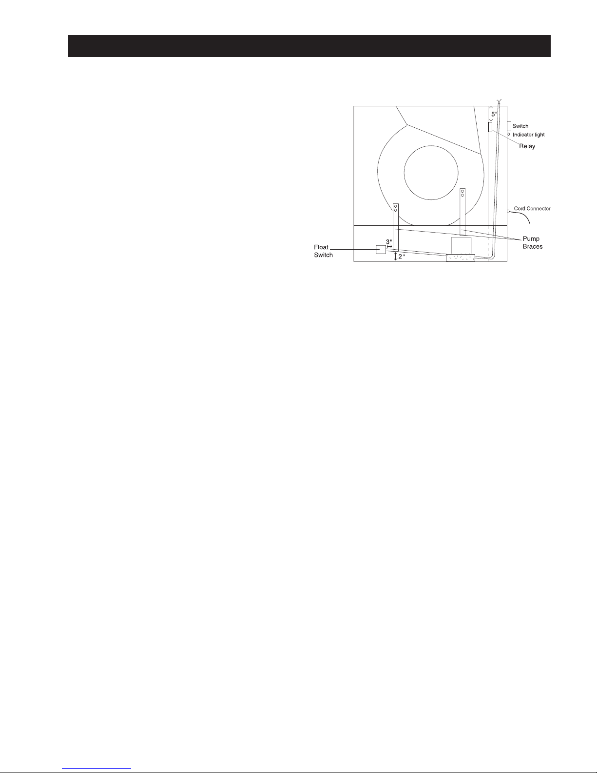
6. Remove the paper from the double-faced tape on the back of the relay. Stick the relay to the aluminum frame on the inside of the
electrical corner approximately 5" from the top of the frame; ensuring the terminals are pointing downward. See diagram.
7. Remove the grate and pads from the side of the unit to the left of the electrical corner.
8. Utilizing the electric screwdriver and the 5/16" hex head bit, attach the supplied pump brace to the blower with the two self-tapping
screws from the hardware bag. This should be done in the same manner as the pump is attached, but place it on the left side of the
blower and ensure the bottom of the brace is 2" from the bottom of the reservoir.
9. The float switch is already attached to the supplied pump brace with an 8" cable tie. Ensure there is 3" of cord from the right side of
the pump brace to the float and that the float does not hit the frame (See diagram). Note: Do not remove cable tie from pump
brace.
10. Run the cord for the float switch up through the bottom of the aluminum frame on the electrical corner.
11. Remove the cord connector. It is located at the bottom of the electrical corner.
12. Drill a 31/64" hole in the electrical corner approximately 7/8" below the switch, and insert the indicator light into the hole. See
diagram.
13. Place the female disconnect on the indicator light labeled L1 on Post 5 of the relay.
14. Remove the blue spade connector and wire from the L position on the switch with a Phillips head screwdriver, and insert the spade
connector from the jumper labeled A into the L position on the switch.
15. Cut the black wire from the power cord just below the blue connector and then strip ½" of plastic from the black wire.
16. Twist the bare end of this wire together with the L2 wire from the indicator light, the A jumper from the switch, and the jumper labeled
B that comes from Post A on the relay. Connect all four of these wires together with a red wire nut from the hardware bag.
17. Unscrew the yellow wire nut that is on the three white wires, and separate the white wire that goes to the pump pigtail and attach the
female disconnect from the hardware bag to this wire. Place this disconnect on Post 2 on the relay.
18. Twist the white wire from the power cord, the white wire from the motor cord, the wire labeled F2 on the float switch, and the jumper
labeled C from Post 7 on the relay all together and connect all four of them with a red wire nut from the hardware bag.
19. Connect the female disconnect that is attached to the wire labeled F1 on the float switch to Post B on the relay.
20. Re-install the cord connector into the electrical corner.
21. Place the electrical corner back into the bottom, but do not re-attach with the screws.
22. Plug the pump and motor in and test the operation of the float switch.
23. Place the two #2 square headed screws into the electrical corner.
24. Place the top back on the unit and re-insert the two #2 square headed screws.
25. Place the blower duct back on the unit and secure it down with the top knob.
Troubleshooting the WC-ASOKIT
WC-ASOKIT not shutting off
• Ensure wiring is done properly.
• Ensure the float switch is at an acceptable depth.
WC-ASOKIT shutting off too soon
• Ensure the float switch is at an acceptable depth.
• Ensure water is at least three to five inches deep.
The Automatic Shutoff Option (WC-ASOKIT) is available at the
time of your WayCool®purchase or as a retrofit kit on a
previously purchased WayCool
®
.
The WC-ASOKIT shuts off the pump when the water level gets
low and prevents the pump from damage. The warranty on the
pump is void if it is run dry.
Automatic Shutoff Option
17
Page 20

General
Support Information
Using this equipment for any other purpose than it was intended or in a way not within the operating recommendations specified in this
manual will void the warranty and may cause personal injury.
This manual is designed to provide comprehensive planning, installation, safety, operation, maintenance, troubleshooting and parts
information. The Table of Contents provides a convenient overview of the information in this manual.
Thank you
The employees of Schaefer Ventilation Equipment would like to thank you for your recent Schaefer purchase. If a problem should arise,
your Schaefer dealer can supply the necessary information to help you.
Ordering Replacement Parts
To order replacement parts contact the dealer from whom you purchased your WayCool®. If you do not have that
information, please call Schaefer Ventilation Equipment at 800-779-3267 to locate a dealer near you.
Keep this manual in a clean, dry place for future reference.
Dealer & Product Information
Dealer’s Name __________________________________________________________________________________
Dealer’s Address ________________________________________________________________________________
______________________________________________________________________________________________
Dealer’s Phone: __________________________________________________________________________________
Date of Purchase ________________________________________________________________________________
Serial Number: __________________________________________________________________________________
18
Page 21
Warranty
Schaefer Ventilation Equipment, LLC. warrants to the original purchaser that our products which prove to be defective in material or
workmanship within one year (unless otherwise specified) from date of purchase will be repaired or replaced at the option of Schaefer
Ventilation Equipment, LLC. F.O.B. Sauk Rapids, Minnesota.
What is Not Covered By The Warranty
The warranty does not cover:
(1) Installations not made in accordance with installation instructions;
(2) Where the operation of the product varies substantially from our operating instructions;
(3) Malfunctions resulting from misuse, negligence, alteration, accident or lack of performance of required maintenance;
(4) Loss of time, inconvenience, loss of use of the product, or other consequential damages.
The above constitutes our sole warranty.
THERE IS NO WARRANTY OF MERCHANTABILITY AND THERE ARE NO WARRANTIES WHICH EXTEND
BEYOND THE DESCRIPTION OF THE FACE HEREOF.
Products with warranty periods that exceed our standard one-year warranty are listed below. These products are subject to all
other provisions as stated in The Schaefer Warranty.
25 Years - Poly Housings
15 Years - Fiberglass Housings
10 Years - VersaHeat®IRLens™ Ceramic Emitters for Gas Units
5 Years - Schaefer GQ Tube Heater Combustion and Heat Exchanger Tubes
3 Years - PC Compatible Controls
2 Years - Certain Manual and Variable Speed Controls
2 Years - Schaefer GQ Tube Heater Burner Controls
1 Year - Schaefer K-Series, 2-Stage, Compact Heater and the Stainless Steel Tube Heaters
Products with warranty periods less than the stated one-year warranty are listed below. These products are subject to all other
provisions as stated in The Schaefer Warranty.
120 Days - VersaHeat®IRLens™Elements for Electric Units
www.schaeferfan.com
©2004 Schaefer Ventilation Equipment
19
 Loading...