

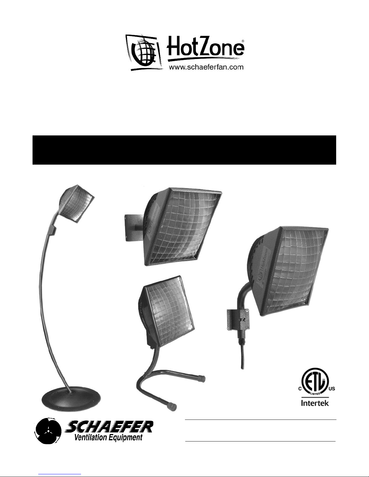
Schaefer HotZone Patio Heater, HotZone Universal Fixed Mount Heater, HotZone Portable Heater Installation & Operation Instructions
Page 1
Schaefer HotZone®
HZE Series Electric Spot Heater
High Output Infrared Heater - 1500/3000 Watt
INSTALLATION & OPERATION INSTRUCTIONS
** HOTZONE® HEATERS MUST BE INSTALLED BY A LICENSED ELECTRICIAN. **
HotZone® Universal
Fixed Mount Heater
HotZone®
Patio Heater
HotZone®
Wall Mount
Heater
HotZone® Portable Heater
3019762
800-779-3267
[email protected] • www.schaeferfan.com
Page 2
Specifications
Congratulations on purchasing a Schaefer HotZone® Electric Infrared Heater. Unlike forced air heaters, HotZone® heaters
warm people and objects, but not the air, with infrared radiation. Your new heater has no moving parts, and should give you
many years of maintenance-free comfort.
HotZone® heaters have the patented, lobster eye inspired, compound reflective IRLlens™ that focuses and directs the
infrared energy into a beam (or a spot). These lenses are lightweight aluminum grids that look like a four-walled
honeycomb structure and are capable of magnifying without overheating.
Because HotZone® heaters focus and direct the infrared energy into a beam:
• HotZone® heaters can be installed out of the way of people and equipment.
• The radiant intensity is much less sensitive to distance from the heater (your head doesn't cook while your feet freeze).
• They deliver up to five times as much infrared energy to the spot, compared to a similar powered, unfocused high
intensity infrared heater.
• They will raise the surface temperature of a 14 square foot area by 15° with a single 1500 watt heater mounted
eight feet above it.
• They will raise the surface temperature of a 25 square foot area by 20° with a single 3000 watt heater mounted
ten feet above it.
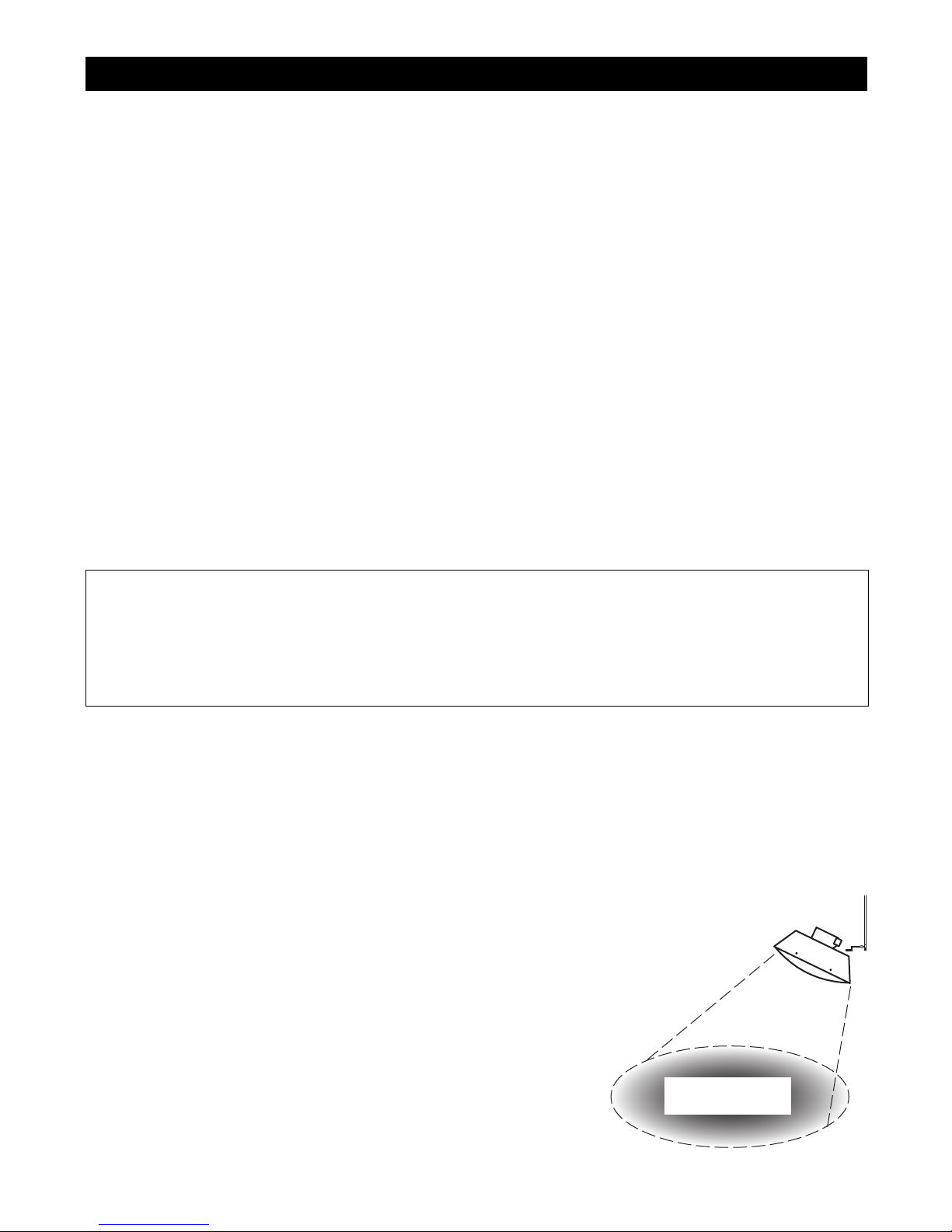
Plan your installation by identifying the area you want heated and how much temperature increase you need. Imagine the
heater as a kind of floodlight and place it so as to cover your target area with enough heat. The temperature increase
resulting from the heater "shining" on a target depends on the power of the heater, the distance from the heater to the target
and how close the target is to the center of the spot. DO NOT allow the heater to be aimed at a wall or any other
combustible material.
The heater unit with fixed mount is ETL certified to UL 2021 (Fixed and Location Dedicated Electric Room Heaters) for
installation both indoors and outdoors. The movable mount options are not ETL certified, but include tip switches and other
features which make them safe for a variety of applications.
WARNING
The safety of this product can only be guaranteed if these instructions are followed. Please keep them for future
reference.
• Always disconnect the heater from the main electrical supply during installation and/or replacement of the
element.
• Infrared energy heats people and objects when it is absorbed. Flammable objects placed too close to the heater
lens could catch fire.
POWER SUPPLY HZE15 120V = 12.5A 208V = 7.2A
All @ 50/60Hz 240V = 6.3A 277V = 5.4A
A = current per stage
HZE30 120/240V = 12.5/6.3A 208V = 7.2A 208V-Delta = 4.8A
240/480V = 6.3A 277V = 5.4A
HZE15 HZE30
Mounting Angle 0° 45° 0° 45°
MINIMUM MOUNTING HEIGHT
MINIMUM DISTANCE TO COMBUSTIBLES (around heater)
Above
Back 9" 9" 18" 18"
Front 9" 30" 18" 41"
Side 9" 9" 18" 18"
Below (in beam) 48" 48" 66" 66"
DIAMETER OF COMBUSTIBLE AVOIDANCE ZONE (below heater)
Distance from lens
12"
24" 36" 42"
36" 46" 52"
48" 56" 62"
60" 72"
72" 82"
72" 72" 72" 72"
6" 6" 9" 9"
26" 32"
COMBUSTIBLE
AVOIDANCE ZONE
2
Page 3

Installation Notes
* IMPORTANT INSTRUCTIONS *
When using electrical appliances, basic precautions should always be followed to reduce the risk of fire,
electric shock, and injury to persons, including the following:
1. Read all instructions before assembling, installing and using this heater.
2. This heater is hot when in use. To avoid burns, do not let bare skin touch hot surfaces. If provided, use handles when
moving this heater. Keep combustible materials, such as furniture, pillows, bedding, paper, clothes and curtains at least
48" (1500 watt) / 66" (3000 watt) from the front of the heater and keep them away from the sides and rear. Do not
install closer than the minimum clearances to any surface.
3. Extreme caution is necessary when any heater is used by or near children or persons that may not have reasonable
judgement around appliances. The heater should not be left unattended while operating.
4. Always unplug heater when not in use.
5. Do not operate any heater with a damaged cord or plug or after the heater malfunctions, has been dropped or damaged
in any manner. Return heater to dealer for examination, electrical or mechanical adjustment, or repair.
6. This heater is not intended for use in bathrooms, laundry areas and similar indoor locations. Never locate heater where
it may fall into a bathrub or other water container.
7. Do not run cord under carpeting. Do not cover cord with throw rugs, runners or similar coverings. Arrange cord away
from traffic area and where it will not be tripped over.
8. To disconnect heater, turn control OFF (if provided), then remove plug from outlet.
9. Connect to properly grounded outlet only. The heater should always be connected to a grounded circuit. If a GFCI
socket is not available, GFCI adapters can be purchased locally. Heater must be installed according to NEC and all
local electrical codes. Be sure the electrical supply is adequate for the heater (voltage/amps/phase) while allowing for
line losses. Use supply wires suitable for 90° C.
10. Do not insert or allow foreign objects to enter the heater or block any ventilation openings as this may cause an electric
shock or fire, or damage the heater. Do not cover or obstruct the heater while operating.
11. A heater has hot and/or arcing and/or sparking parts inside. Do not use it in areas where gasoline, paint, flammable
liquids or highly combustible dusts are used or stored.
12. Use this heater only as described in this manual. Any other use not recommended by the manufacturer may cause fire,
elecric shock, or injury to persons.
13. Do not use an extension cord with this heater.
14. If the unit is installed in proximity of tents or awnings, please be sure that recommended installation heights and
clearances are respected, and that the heater is not in direct contact with the tent or awning material.
15. Allow for user angle and directional adjustment, if possible, as heating requirements change. The optimal mounting
angle is between directly down and 45°. Comfort is best obtained with the heater off to one side and angled at 35°.
Install heaters so that items in the infrared beam do not overheat.
16. Burned-out elements cannot be repaired and must be replaced. The element can be replaced by the user; please follow
the instructions provided. Always disconnect the heater from the main electrical supply during installation and/or
replacement of the heater element.
* SAVE THESE INSTRUCTIONS *
3
Page 4
Installation Notes cont'd
** HOTZONE® HEATERS MUST BE INSTALLED BY A LICENSED ELECTRICIAN. **
For an effective and efficient heating solution, some or all of the following heater controls can be utilized: on/off switches,
power controllers (dimmers), timers and thermostats. Contact your local licensed electrician or your Schaefer HotZone®
dealer for recommendations and assistance.
CAUTION
** DO NOT USE THIS HEATER FOR APPLICATIONS FOR WHICH IT IS NOT INTENDED **
HotZone® heaters are intended for heating people or objects from a distance in excess of the minimum distance to
combustibles. Use of the heater for applications such as paint drying or equipment heating from a short distance
where infrared energy will reflect back toward the heater will overheat the element, causing early element failure
and negating the warranty.
CAUTION
** DO NOT USE THIS HEATER AS A PORTABLE HEATER **
HotZone® heaters are designed, listed and approved as fixed and location-dedicated heaters. If the heater is used as
a portable heater there is a great risk of fire and/or heater damage if the heater is placed too close to combustibles
or if the heater tips over.
The Schaefer HotZone® electric heater can be wall- or ceiling-mounted from an existing or new electrical junction box
utilizing the universal mounting kit.
The angle adjustment assembly on the back of the heater can be reversed to minimize the torque on the assembly and allow
the heater to be aimed as desired. Typically, the assembly should be in the middle of the back of the heater for downward
facing ceiling mounting, and toward the bottom and forward on the heater for downward through horizontal facing wall
mounting (see page 5).
Be sure you are supplying the correct voltage to the heater, allowing for line losses. The heater's voltage requirements are
marked on its shipping box and on its ETL certification label. Too much voltage will burn the heater element out
immediately. Too little voltage or inadequate current capacity will cause the heater element to run cool, and can cause
the supply circuit to overheat dangerously.
Always be sure the supply voltage is turned off to the junction box before starting installation.
After the heater is installed and power is turned on, the element should begin glowing within 20 to 30 seconds and glow a
uniform red-orange color within two to three minutes. If it begins glowing more quickly or glows very brightly, turn the
heater off immediately and re-check the supply voltage.
The heater will smell very hot for the first few minutes of operation, then will stop emitting an odor.
If the position of the heater needs to be adjusted after it is attached to the mount, be very careful. DO NOT GRAB THE
HEATER HEAD AND TWIST! Adjustment up and down requires loosening of the adjustment screws (see page 5). The
heater itself cannot be adjusted from side to side.
Do not touch or allow any person or object to come in contact with the heater during operation as shell temperature will
reach about 190° F.
4
Page 5
ANGLE ADJUSTMENT
Angle Adjustment
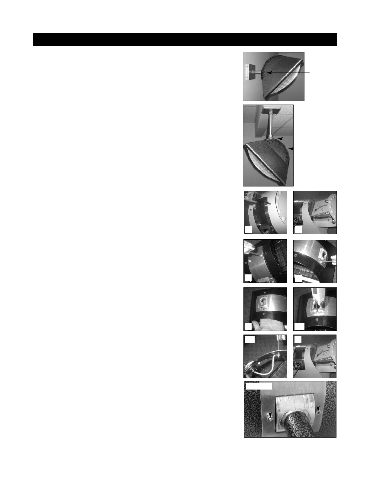
The angle adjustment assembly on the back of the heater is designed for mounting
flexibility, but the correct configuration should be determined before the heater is
attached to the mount.
The angle adjustment assembly has approximately 40 degrees of motion, which
allows the heater to be aimed at the desired target. It can also be reversed for
additional range of motion, and to reduce the amount of torque the heater exerts
on the assembly.
• Heaters to be mounted on the wall should have the assembly attached below
the center of the heater (standard configuration - Figure 1).
• Heaters to be mounted on the universal ceiling mount and aimed sideways
should have the assembly attached above the center of the heater
(standard configuration, heater mounted "upside down" - Figure 2).
• Heaters to be mounted on the universal ceiling mount and aimed down should
have the assembly attached in the center of the heater (assembly needs to be
reversed - Figure 3).
REVERSING THE ANGLE ADJUSTMENT ASSEMBLY
Save all hardware for re-use!
1. Remove the two cap screws from the back of the heater, which are holding the
louvered element tray in place.
Figure 1
Figure 2
Figure 3
1
2
2. Slide the element tray out of the heater. Pull the high temperature element
wires through the hole in the angle adjustment assembly to free the element.
3. Remove the two allen screws that attach one end of the curved mounting plate
to the heater.
4. Remove the two allen screws that secure the other end of the curved mounting
plate, internal ring clamps and angle adjustment assembly to the heater. Detach
the ground wire as well.
5. Reverse the orientation of the curved mounting plate and angle adjustment
assembly.
6. Re-attach the curved mounting plate, ring clamps and angle adjustment
assembly to the heater. Re-attach the ground wire.
7. Feed the high temperature element wires through the angle adjustment
assembly and slide the element tray back into the heater. Fasten the element
tray to the heater.
The angle adjustment assembly is adjustable up and down. Be sure to loosen the
allen screws before moving the heater, and then tighten them just enough to hold
the unit in place. (Figure 4) Overtightening can bend the frame and damage the
unit.
3
5
6b
Figure 4
4
6a
7
5
Page 6

Maintenance & Troubleshooting
MAINTENANCE
• The heater body can be washed with gentle detergent and a soft wash cloth. Do not use a pressure washer. With an air
hose regulated to 30 psi, blow off any dust and dirt from in front of the heater that has accumulated on the reflective
surfaces of the heater and reflective lens. A vacuum cleaner can be used as well. Accumulated dirt will degrade
performance.
• Blow off or vacuum any accumulated dirt on the vent holes of the heater and make sure they are not bent such that the
vent area is reduced.
• When not installed or in use, store the heater in a dry, dust-free place and be sure the lens-assembly is protected from
any possible damage.
• The heater lens is manufactured from thin aluminum and is easily bent and damaged. Heater performance deteriorates
when the lens is bent or damaged. In most cases the lens can be bent back into shape by hand or with pliers. If the
lens cannot be repaired, it can be replaced.
• If the heater is turned on when wet it may steam and sizzle a bit but this will subside as it dries.
TO CHANGE THE COLOR OF THE HEATER
• The outer housing of the heater can be spray painted with high-temp metal paint. DO NOT paint the bare aluminum
lens or inside surfaces. (The bare aluminum reflects 100% of the infrared heat; paint absorbs infrared and will cause the
unit to overheat. This will void the warranty.)
TROUBLESHOOTING
At full power and after two to three minutes of warm-up time, the heater element should glow a warm orange color, similar
to the color of coals in a hot fire.
If the element does not warm up at all:
• Is the service power on at the circuit breaker?
• Is there a switch or dimmer in the circuit? Is the switch on?
• Is the heater connected to the appropriate power source (plug or junction box)?
• Is the element in working condition? Burned out elements normally have visible burn marks on the face of the element.
If there is no evidence of damage, and you still suspect the element, turn off the power at the circuit breaker, disconnect
the service power and check element resistance. It should be between 10 and 50 ohms, depending on the element.
• Are the high temperature leads connected to the element? Turn off the power at the circuit breaker. Remove the element
from the heater housing and check the connections at the back of the element.
If the element barely glows:
• Is the heater on a dimmer? Is the dimmer turned full on and operating correctly?
• Is the heater connected to the correct line voltage (under load condition) for its element type? 120V models must be
plugged into an outlet that provides 120V. If the outlet provides less than 120V the element will not operate correctly.
• Is the element wired correctly, and are all connections intact? Note: three phase devices where one leg is disconnected
will operate with reduced output.
If the element glows a bright orange-white and heats up very quickly:
• The heater is receiving too much power and will burn out very quickly if it is not turned off.
• Is the heater wired correctly for its element type?
• Is the element damaged? A short circuit between adjacent coils will cause some coils to go dark and some coils to
overheat. Damaged elements cannot be repaired and must be replaced.
6
Page 7
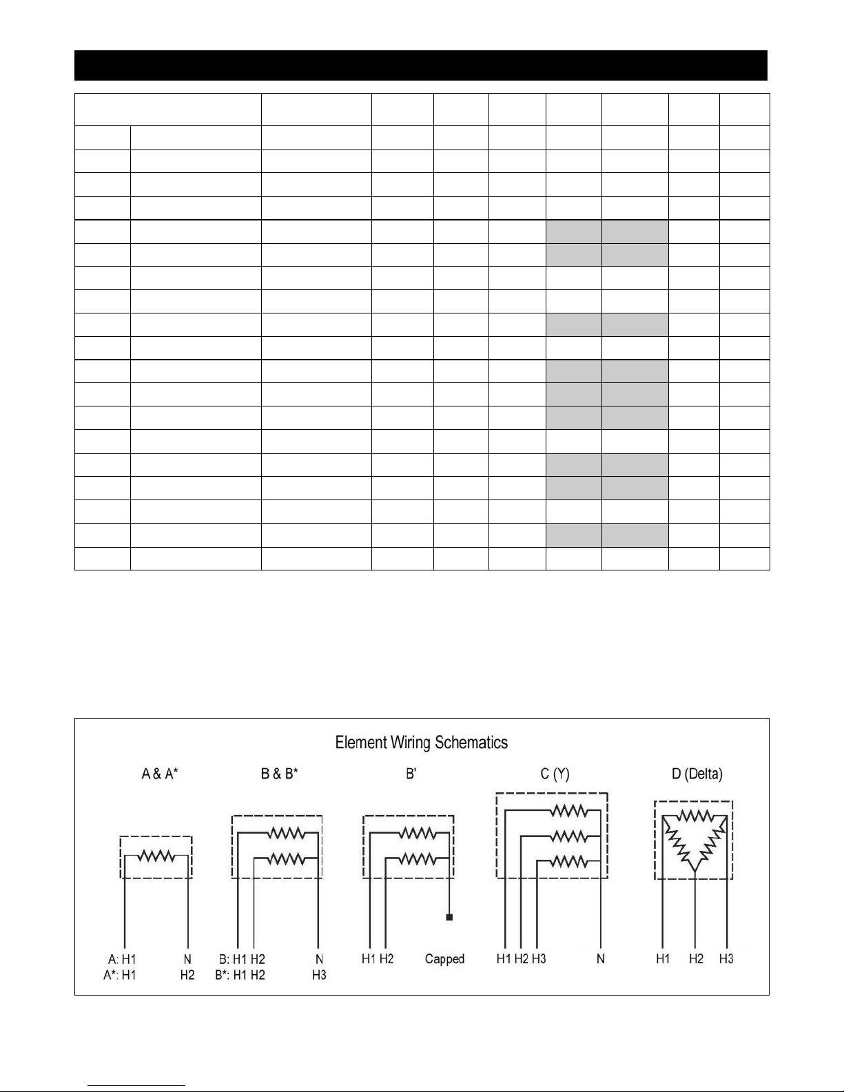
eater Elements
H
Power No. of No. of Voltage Alt. Voltage
Element Heater (W) Stages Wires Schem. (V) Schem. (V)
7501 HZRE15120C HZS15120 1500 12 A120
7503 HZRE15208C HZS15208 1500 12 A* 208
7504 HZRE15240C HZS15240 1500 12 A* 240
7505 HZRE15277C HZS15277 1500 12 A277
75301 HZRE30120/240C HZS30120/240 3000 23 B120 B' 240
75302 HZRE30208C HZS30208 3000 23 B* 208
75303 HZRE30208YC HZS30208Y 3000 34 C208 (1)
75304 HZRE30208DC HZS30208D 3000 33 D208
75305 HZRE30240/480C HZS30240/480 3000 23 B* 240 B' 480
75309 HZRE30480C HZS30480 3000 12 A* 480
75501 HZRE50120C HZS50120 5000 34 C120
75502 HZRE50208SC HZS50208 5000 23 B* 208
75503 HZRE50208YC HZS50208Y 5000 34 C208 (1)
75504 HZRE50208DC HZS50208D 5000 33 D208
75505 HZRE50240/480C HZS50240/480 5000 23 B* 240 B' 480
75507 HZRE50277C HZS50277 5000 23 B 277
75508 HZRE50346C HZS50346 5000 12 A 346
75510 HZRE50480YC HZS50480Y 5000 34 C480 (2)
75511 HZRE50600C HZS50600 5000 12 A* 600
Notes:
• All heaters have a ground wire attached to the heater shell (not the element).
• Alternate connections for dual service elements are under "Alternate Schematic".
• Schematics with an asterisk (A*, B*) connect to a common hot wire (H), not a neutral wire (N).
• Schematics with an apostrophe (B') require the neutral wire (N) to be capped.
• Heater elements and wiring schematics that allow high/low staging are shaded.
(1) Voltage between hot and neutral is 120V.
(2) Voltage between hot and neutral is 277V.
7
Page 8
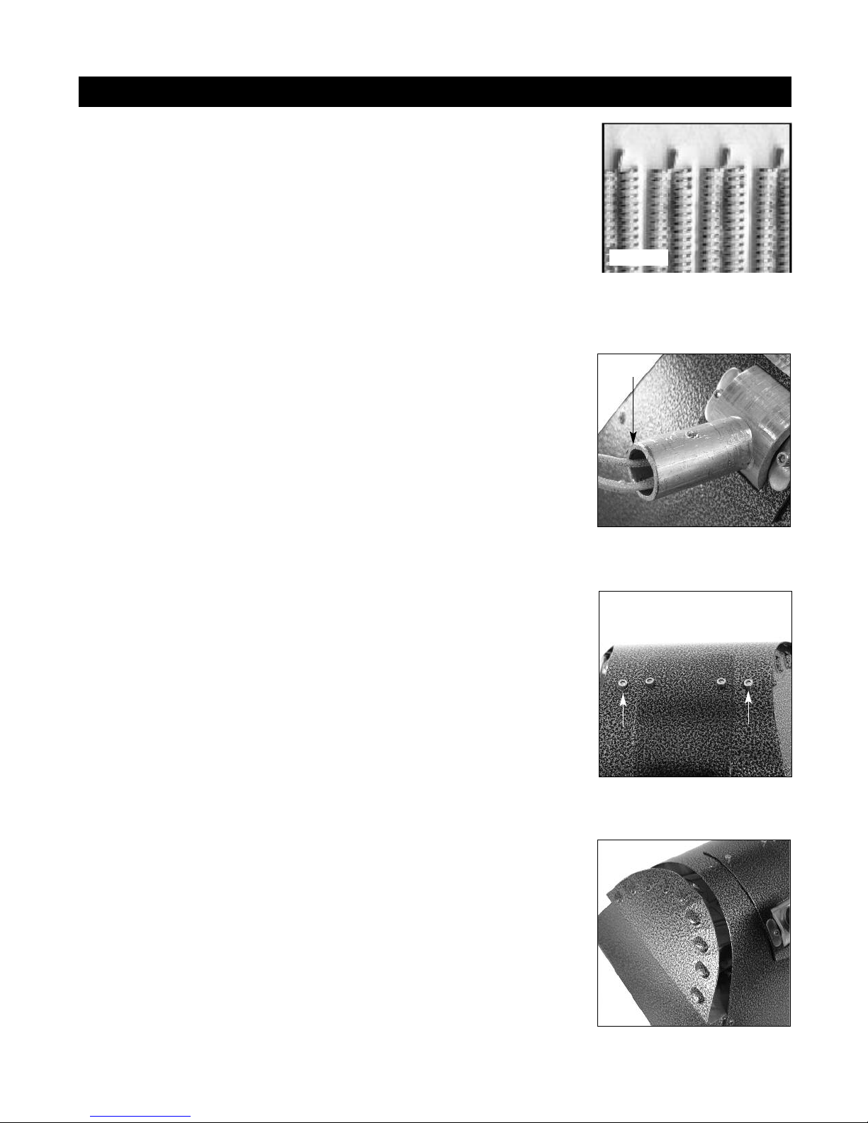
Element Replacement
HEATER ELEMENT
The heating element operates at approximately 1800° F. The element is resistant to
thermal and mechanical shock, and is appropriate for use in both wet and dry locations.
(Figure 5)
The element has an expected life of 2000 hours. When an element burns out, it cannot
be repaired and must be replaced. For replacement, have your heater model number
available and call your dealer or Schaefer Ventilation to order the correct element.
Replacement high-temperature lead wires must be capable of handling 1000º F and have
stainless steel terminals.
To replace the element:
Always disconnect the heater from the main electrical supply during installation
and/or replacement of the heater element.
1. Turn off power supply to the heater.
Figure 5
Figure 6 - High-temp lead
wires exit mounting stub.
2. Carefully remove the heater from the mount and disconnect the power supply. The
original white high-temperature lead wires should be coming out through the
mounting stub. (Figure 6)
** Be sure to save all hardware for re-use! **
3. Place the heater on a level, flat surface. Be careful not to bend the lens (lay the
heater on a soft or padded surface, such as a folded towel or bubble wrap).
4. Remove the two allen screws that hold the element frame in place. (Figure 7)
5. Carefully slide the element frame out to one side. Notice the high temp wires are
being pulled through the mounting stub; feed them out as they are pulled by the
frame. (Figure 6 and Figure 8)
Figure 7 - Two allen screws
hold element frame in housing.
Figure 8 - Element in frame
slides in/out of housing.
8
Page 9
Element Replacement cont'd
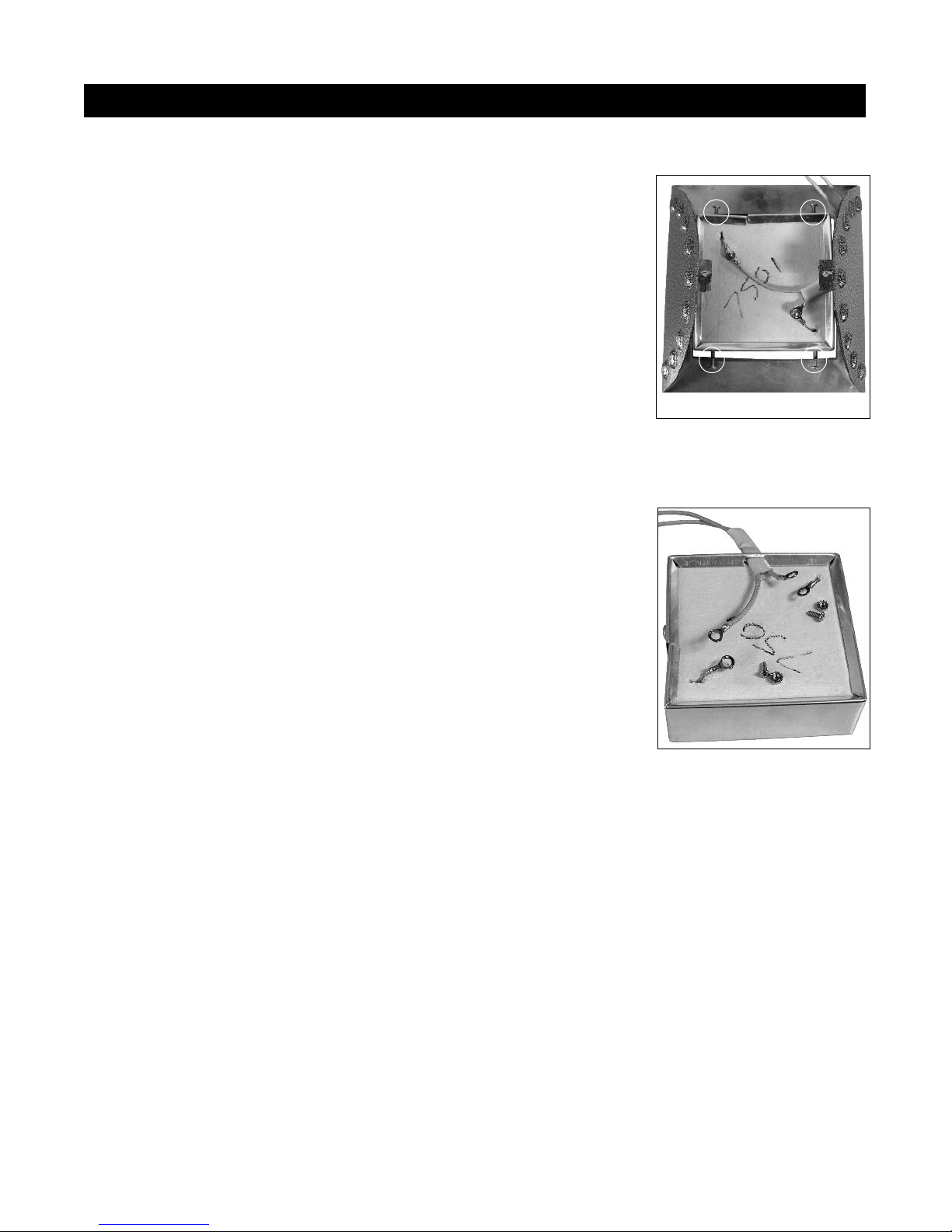
6. Lay the element frame as flat as possible next to the heater (still attached by the
lead wires). (Figure 9)
7. Disconnect the lead wires from the ring terminals on the used element. Do not lose
the hardware! (Figure 10)
8. Loosen the four screws that hold the element in the frame. Remove the used
element. Be careful not to knock off or puncture the four insulating pads on
the element wrap. (Figure 9)
9. Remove the single screw that holds the element wrap in place. Remove the old
element from the wrap and replace with same model of new element. Be sure to
replace the screw.
10. Lay the new element into the frame. Center it and then tighten the four screws to
hold it in place. Be careful not to knock off or puncture the four insulating pads on
the element wrap.
Figure 9 - Element in frame
with lead wires connected.
four screws hold element
Figure 10 - Lead wires
disconnected from element.
11. Attach the high-temperature lead wires using the hardware that was removed from
the used element. Follow the appropriate wiring schematic on page 7. (Figure 9)
12. Carefully slide the element frame back into the heater. The lead wires must be
carefully pulled back through the mounting stub as the element is slid into place
(leaving them loose in the heater housing can cause them to overheat). (Figure 6)
13. Replace the two allen screws that hold the element frame in place. (Figure 7)
14. Using a resistance meter, check for element continuity and shorts to ground. The
resistance from a hot lead to ground should be several mega-ohms, and the resistance
between hot leads should be between 10 and 50 ohms, depending on the element.
15. Re-attach the heater to the mount using the hardware removed in Step 2. Connect the
heater to electrical supply and test for operation.
9
Page 10
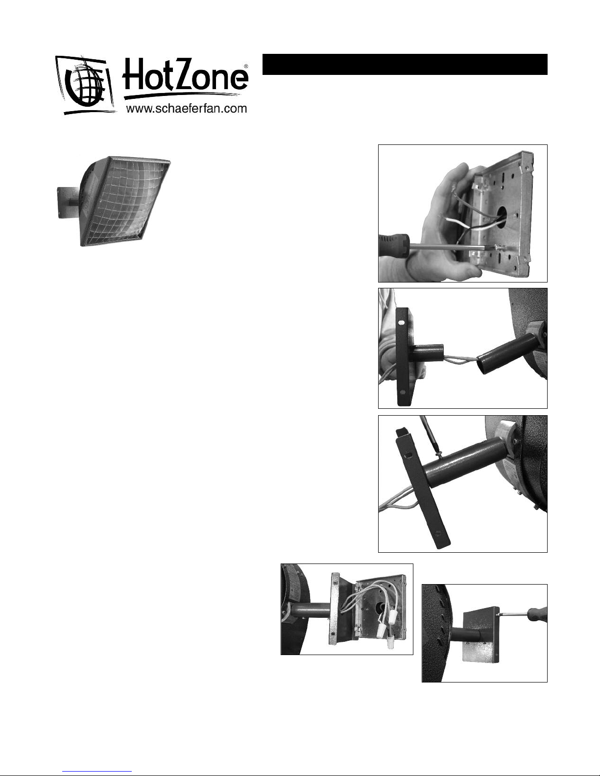
HotZone® Universal Fixed Mount Assembly
Tools required:
#2 Phillips head screwdriver
Tools required to attach universal mounting plate to junction box
This mount requires the heater to be attached to
a junction box in the ceiling or wall.
Choose a location that meets or exceeds the
minimum distance to combustibles on all sides
and in front of the heater. Mount the heater at
least 72" above the ground.
The heater does NOT include hardware for
attaching the mount to the ceiling or wall.
1. Turn off supply voltage to the junction box at the panel.
2. Thread the supply wires through the hole in the center of the universal
mounting plate. Orient the universal mounting plate so the four cover plate
mounting holes are on the sides, not the top and bottom. Attach the
universal mounting plate to the junction boxwith appropriate user-supplied
screws. For additional support, secure the mounting plate to the ceiling or
wall using appropriate screws (not provided) at the corners of the universal
mounting plate.
NOTE: If the heater is to hang from the ceiling, refer to the Angle Adjustment
instructions to reverse the angle adjustment assembly before continuing.
3. Thread the lead wires from the heater through the appropriate tube
(provided - choose the 8" tube for ceiling mount; 4" tube for wall mount)
and then through the stub in the cover plate.
4. Secure the tube to the heater stub with a trilobal screw (provided). Secure
the tube to the cover plate stub with the remaining trilobal screw.
5. Recruit an assistant to hold the heater. You may need to cut the clips off the
ends of the lead wires and strip them to accommodate wire nuts. Use wire
nuts to connect the lead wires from the heater to the power supply. Be sure
the lead wire with the green label is connected to the green (ground) power
supply wire.
6. Lift the heater up to the universal mounting plate
and carefully coil the wires and connections into
the junction box. Secure the cover plate to it with
the four screws (provided). Be sure all screws
are secure and sufficient to hold the weight of
the heater. If any mounting hardware is loose or
insufficient the heater may fall.
7. Turn on the power supply and test operation.
10
Page 11

Warranty
Schaefer Ventilation Equipment, LLC
Schaefer Limited Warranty Policy
Schaefer Ventilation Equipment, LLC (SVE) provides the following limited warranty from the date of invoice to
the initial purchaser of our products or to its customer with a dated proof of purchase:
I. Two-year coverage (unless otherwise indicated below) applies to all products, components and
assemblies provided by SVE that prove to be defective in material or workmanship. Any such defective
product will be repaired or replaced at SVE’s option, with the defective product or component returned,
upon approval, to SVE, F.O.B Sauk Rapids, Minnesota.
II. This warranty does not cover:
a. Failure, damage or malfunction as a result of:
i. Improper installation or installation not in accordance with installation instructions.
ii. Operating conditions that vary from SVE’s operating instructions.
iii. Misuse, abuse, negligence, alteration, or accident.
iv. Transporting the product.
v. Improper operation or lack of appropriate or regular maintenance of the product.
b. Loss of time, inconvenience, loss of use of the product or other consequential or incidental damages.
c. Parts that need replacement due to normal wear and tear.
d. Superficial or cosmetic rust or corrosion.
e. Any product whose name plate has been removed.
Products with warranty periods that differ from the standard 2-year warranty are as follows:
• Poly Housings 25 years
• Fiberglass Housings 15 years
• Low-intensity Tube Heater Exchange Tubes 5 years
• Heavy-Duty Industrial Wash-Down Fans (with VWD motors) 3 years
• K-Series, 2-Stage, Compact and Stainless Steel Tube Heaters 1 year
• Quartz and Zubri Heaters 1 year
• Big Dog™ Fans 1 year
• Shutter Motors and Aluminum Riveted Fan Blades 1 year
• Epoxy Line Wash down fans (with EWD motors) 1 year
• Evaporative Cooling Pads 180 days
• HotZone® Electric Elements 120 days
• Quartz Bulbs 90 days
• Tuff & Gusty Fans 90 days
• Any product or part as noted as an exception to the standard
2-year warranty in the product’s operating manual.
SVE reserves the right to add or delete products from this exception list at any time.
THERE ARE NO WARRANTIES OF MERCHANTABILITY OR FITNESS OF USE.
SVE reserves the right to change product design and specification without prior notice or liability.
The above constitutes the sole warranty offered by Schaefer Ventilation Equipment, LLC.
Effective March 1, 2010.
All information, illustrations and specifications provided here are based on the latest product information
available at the time of printing. Product specifications subject to change.
11
Page 12

800-779-3267
www.schaeferfan.com
©2010 Schaefer Ventilation Equipment 11-17-10
 Loading...