

Page 1
SCHAEFER GmbH | Winterlinger Straße 4 | 72488 Sigmaringen | Germany
Telefon +49 7571 722-0 | Telefax +49 7571 722-98 | [email protected] | www.ws-schaefer.de
Installation Instructions
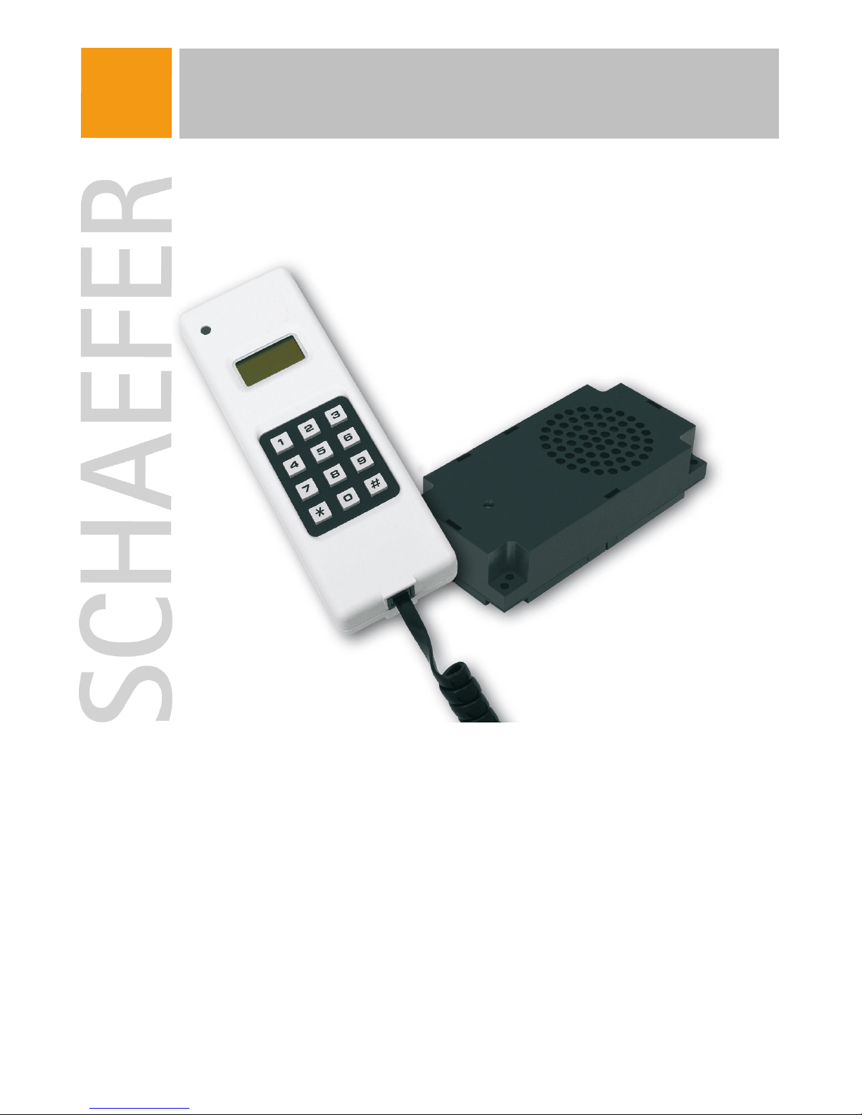
FPM 32 Intercom System
Page 2

© SCHAEFER GmbH Installation Instructions FPM 32
2
SCHAEFER GmbH
Winterlinger Straße 4
72488 Sigmaringen
Germany
Phone +49 7571 722-0
Fax +49 7571 722-99
[email protected]
www.ws-schaefer.de
Support
If you have any questions regarding this product please contact:
Phone +49 7571 722-51
Fax +49 7571 722-99
[email protected]
Copyright
Duplication (copy, print, microfilm or any other form) as well as electronic spreading
of this document is only permitted after formal written consent of SCHAEFER GmbH.
SCHAEFER GmbH reserves the right to carry out alterations of technical details
without prior notice.
For all transactions our General Conditions of Sale and Delivery shall be applicable.
All rights reserved.
Version : 1.0.0
Ress. : 010794
Revision : 2006-09-08
Revision Index : 1
Page 3

© SCHAEFER GmbH Installation Instructions FPM 32
3
1. Installation 4
1.1 Wiring 4
1.2 Connection of wires 4
1.2.1 Handset 4
1.2.2 Hands-free speakerphone LMK 5
2. Addressing the participants 6
3. Adjustments 6
3.1 Calling the adjustment mode 6
3.2 Language 6
3.3 Addressing 7
3.4 Assignment of the hands-free speakerphones 7
3.5 Automatic cancellation of calls (without FPM 8800) 8
3.6 Internal alarm (only with FPM 8800) 9
4. Operation of the hands-free speakerphone LMK 10
4.1 Addressing 10
4.2 Delaying the alarm button (prevention of misuse) 10
4.3 Volume 10
5. Specifications 11
Page 4
© SCHAEFER GmbH Installation Instructions FPM 32
4
1. Installation
1.1 Wiring
All participants in the system are parallely connected to one cable. For this
connection a five-wire cable is needed. The required cross-section is determined by
the extension of the system. Extension means the distance between the most remote
participants in the system.
Depending on this distance the following guidelines are valid:
chart 1
As a matter of principle shielded and twisted paired wires (STP) must be used.
When installing the cables no topological guidelines must be met, i. e. apart from
straight-line connection tree and star structures are also possible. For getting a good
speech quality the number of joints should be at a minimum. Furthermore there must
be good contacts between the cable segments.
1.2 Connection of wires
The five wires are marked as follows: HIGH, LOW, UB, GND and LINE. These are to
be connected parallely with all handsets and hands-free speakerphones.
1.2.1 Handset
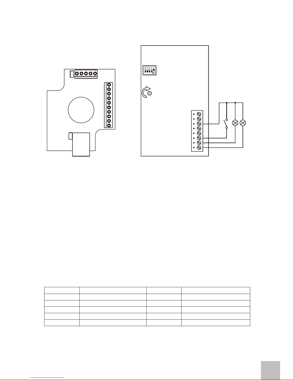
The screw terminals of the handset are inside the wall fixture. If the handset is picked
up the cover may be removed by unscrewing the two screws. The ten-pole terminal
is meant for connection of the participants. For each signal two screw terminals are
available.
Power supply is connected with any handset in the system. To keep losses from line
resistance low it is recommended to use a centrally placed handset for this purpose.
At this device the bridges JPR1 and JPR2 inside the wall fixture must be used. Power
supply is connected to the terminals „GND“ and „12..30 V DC“. With all other
handsets no bridges must be used.
extension of the network [m] nominalcross-section [mm²]
up to 500 0,5
up to 1000 1
Page 5
© SCHAEFER GmbH Installation Instructions FPM 32
5
LINE
GND
UB
LOW
HIGH
n
o
t
u
s
e
d
1
2
.
.
.
3
0
V
D
C
n
o
t
u
s
e
d
n
o
t
u
s
e
d
G
N
D
LINE
GND
UB
LOW
HIGH
JPR1
JPR2
dipswitch
volume
HIGH
LOW
UB
GND
LINE
alarm button
indicator “com munication”
indicator “alarm recall”
Fig. 1: Connection handset Fig. 2: Connection hands-free speakerphone
1.2.2 Hands-free speakerphone LMK
The hands-free speakerphone has the following terminals:
− five wires (HIGH, LOW, UB, GND, LINE)
− alarm button
− indicator „communication“ and indicator „alarm recall“
The connections for the indicators are open collectors (npn max. 30 V, 50 mA).
The alarm button and the indicators need to be connected as shown in figure 2.
If the indicators shall be run with another voltage than the supply voltage UB they
also can be fed from another source. Then the reference potential of the FPM 32
(GND) and the reference potential of the external source must be connected.
If an additional alarm signal with other potential is required a button with two
separated contacts must be used.
Alternatively the hands-free speakerphone can be connected by means of a ten-pole
flat cable.
cable signal cable signal
1 (red) indicator “alarm recall” 6 LINE
2 UB 7 GND
3 indicator “communication” 8 UB
4 UB 9 LOW
5 alarm button 10 HIGH
chart 2
Page 6

© SCHAEFER GmbH Installation Instructions FPM 32
6
2. Addressing the participants
All participants in the system are addressed. Each handset gets an address between
0 and 15. The handset with the address 0 is automatically the one with exchange
function and gets some special authority. Address 1 is the first extension, address 2
the second etc.
If the remote emergency call system FPM 8800 is used the address „extension 15“
must not be addressed as this is reserved for the system FPM 8800.
Addressing of the handsets is made by calling the „adjustments“ mode and
addressing of the hands-free speakerphones is made by a dipswitch.
For making the new addresses known to the system the power supply must be
disconnected after each change of address or a system check must be started from
the exchange.
The exchange automatically starts a system check after the power supply is
connected or when power supply exists again after a power failure. After installation
you may start a system check to check the connection to the other participants. If
participants are missing in the list or if you get the message “no answer” the
connections to the respective participants must be checked.
3. Adjustments
Please read this chapter carefully. Wrong programming of the addresses or wrong
assignment of the hands-free speakerphones can have a negative effect on the
function of the system.
3.1 Calling the adjustment mode
Wait until the device changes to the power save mode (display is inactive). Then put
in the four figures 2, 4, 6, 8. In the display the date of the software is now indicated.
Then press the key „5“ for getting to the „adjustments“ mode.
3.2 Language
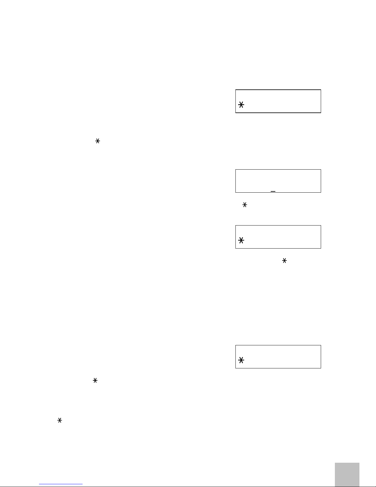
In the first item the language is chosen.
The display indicates:
Choose either German or English messages by aid of the keys “ ” or “ # ”.
D E U T S C H
#
E N G L I S H
Page 7
© SCHAEFER GmbH Installation Instructions FPM 32
7
3.3 Addressing
In the next item the address of the participant is programmed.
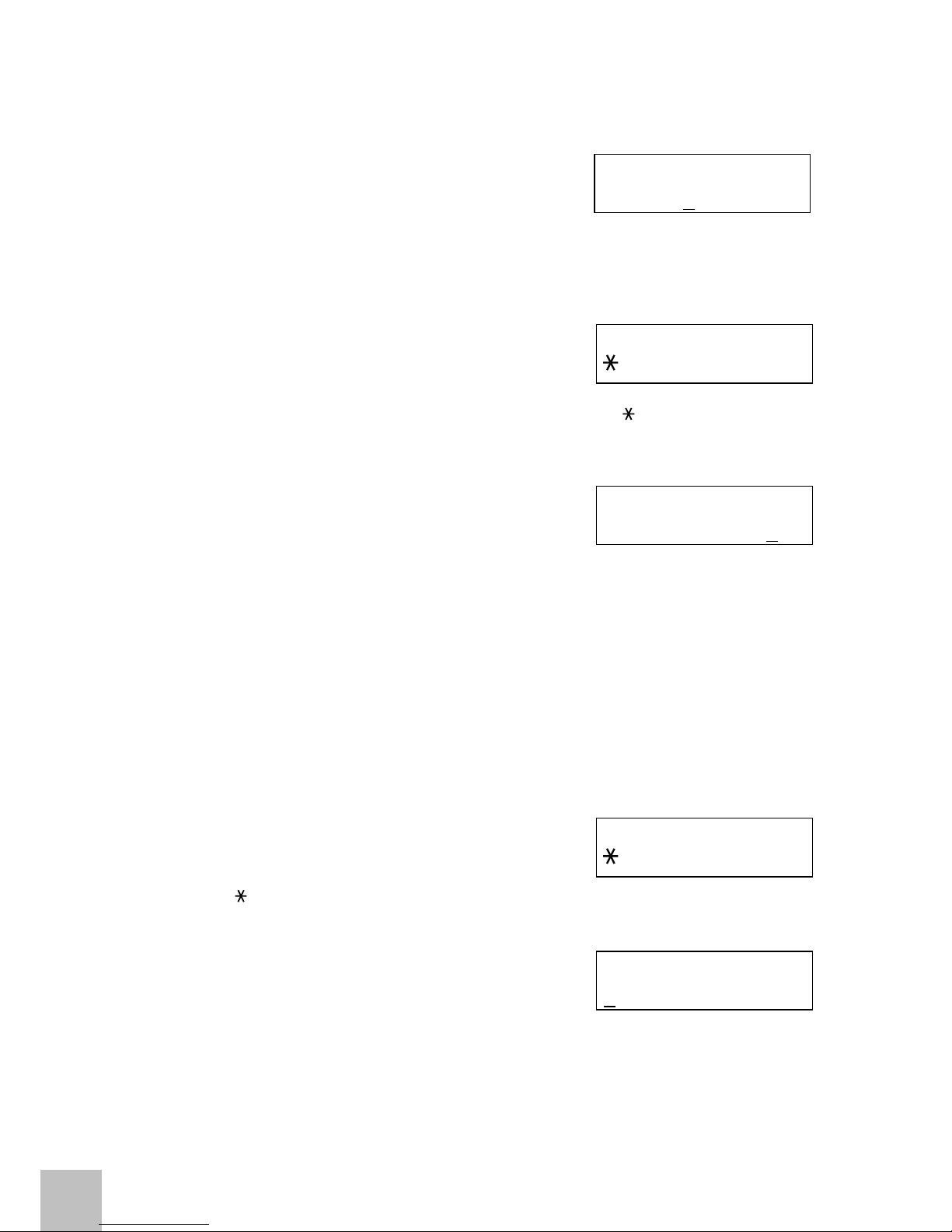
The display indicates:
Press the “ # ”-key for confirming the indicated address and leaving this item.
Press the “ ”-key for changing the address of the handset. Each handset gets a
unique address between 0 and 15. Address 0 is meant for the handset with exchange
function. The addresses 1 to 15 are meant for the extensions.
The display indicates:
Put in the new address of the handset by means of the figure keys. Please note that
two digits should be typed (00, 01, ..., 15). By pressing the “ ”-key you can return to
the first digit.
By pressing the “ # ”-key the input is confirmed.
The display indicates:
Press the “ # ”-key for confirming a new address. By pressing the “ ”-key the
change can be deleted. Then the old address will still be valid.
3.4 Assignment of the hands-free speakerphones
Basically emergency calls can be analysed and indicated both at the exchange and
at each extension. Under this item particular hands-free speakerphones can be
assigned to an extension. If there are emergency calls from other hands-free
speakerphones they are ignored by this extension. At the handset with exchange
function this item is not available.
The display indicates:
Press the “ ”-key for not making an assignment and leaving this item.
Press the “ # ”-key for making an assignment.
If there has already been an earlier assignment the selected hands-free
speakerphones are indicated in the first line of the display one by one. If so press the
“ # ”-key for keeping the existing assignment and leaving this item. Press the “
”-key for changing the assignment.
A D D R . X X
N
O # Y E S
N E
W A D D R
0 0
A D D R . X X
N
O # Y E S
S E
L E C T F
N
O # Y E S
Page 8
© SCHAEFER GmbH Installation Instructions FPM 32
8
The display indicates:
Put in the number of hands-free speakerphones by means of the figure keys (01,...,
15) and confirm the input by pressing the “ # ”-key.
Put in „00“ if you do not want to make any assignment.
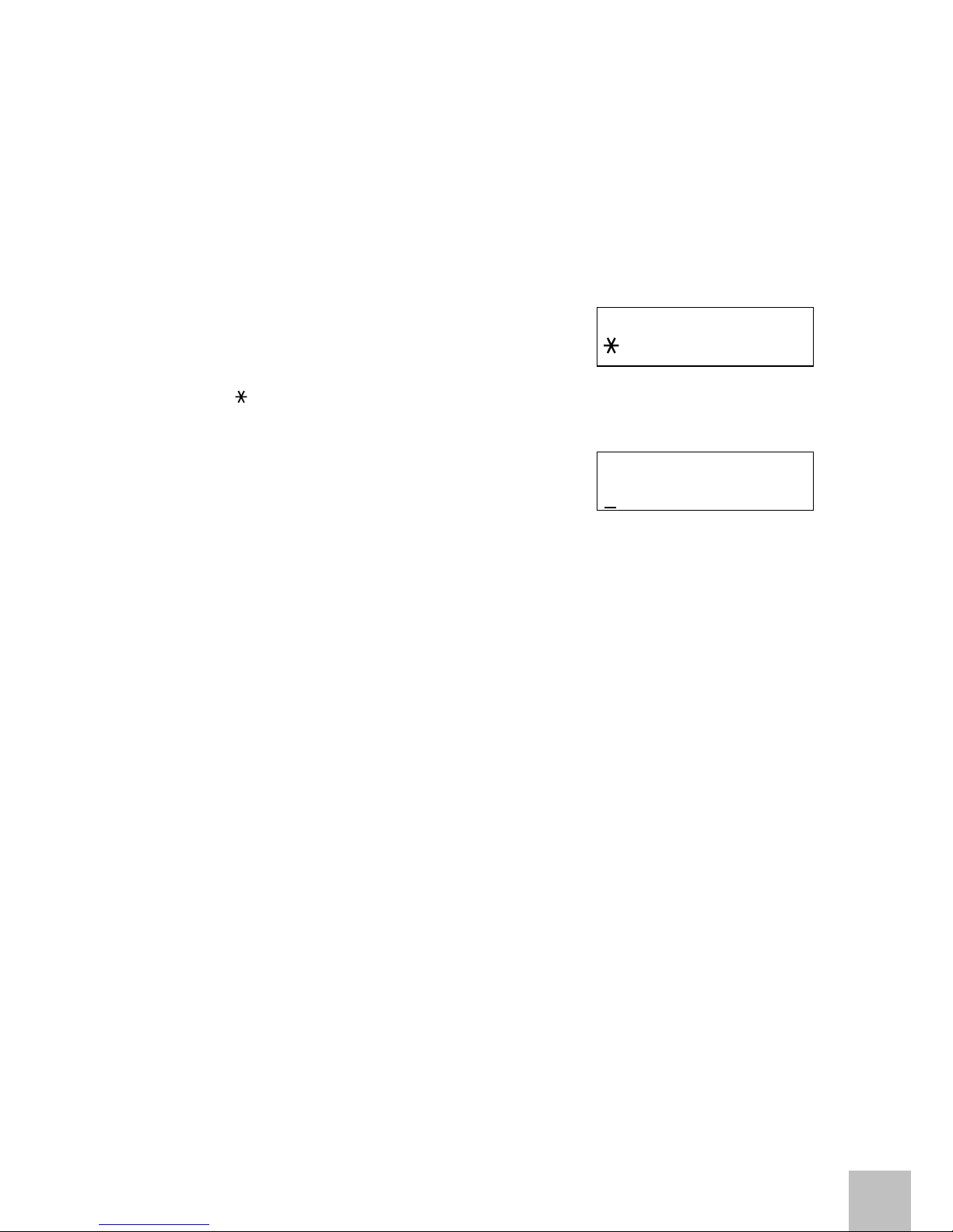
The display indicates:
Confirm the number by pressing the “ # ”-key. Press the “ ”-key for leaving this
item.
The display indicates:
Now put in the addresses of the assigned hands-free speakerphones one by one by
means of the figure keys and confirm each input by pressing the “ # ”-key.
3.5 Automatic cancellation of calls (without FPM 8800)
Basically the emergency calls are indicated until they are answered by a handset. If
the FPM 32 is only used for intercom purposes and not as an emergency call system
a limit of time can be determined after which the emergency calls at all handsets are
cancelled. This adjustment is valid within the whole system and can be changed at
the handset with exchange function only.
The display indicates:
Press the „ “-key if you do not want an automatic cancellation of calls.
Press the „
# “-key and you are asked to put in the time limit.
The display indicates:
Now you may determine a time between 1 – 99 minutes. Finish your input by
pressing the . „
# “-key and confirm the value once again.
N U M B E R ?
0 0
N U M B . X X
N
O # Y E S
N O
. 1
A D
D R . ? 0 0
A L
A R M Z L
N
O # Y E S
Z
T
. L I M I T
0 0 M I N
Page 9
© SCHAEFER GmbH Installation Instructions FPM 32
9
3.6 Internal alarm (only with FPM 8800)
Before the FPM 8800 transmits an emergency call it is possible to answer it internally
at one handset or at the exchange. The time for which the emergency call is only
indicated internally can be changed at the handset with exchange function only and is
valid within the whole system.
The display indicates:
Press the „ “-key if you do not want an internal alarm.
Press the „ # “-key and you are asked to put in the time limit.
The display indicates:
Now you may determine a time between 0 and 60 seconds. Finish your input by
pressing the „ # “-key and confirm the value once again.
I N T A L A R M
N
O # Y E S
I N
T A L A R M
0 0
S E C
Page 10
© SCHAEFER GmbH Installation Instructions FPM 32
10
4. Operation of the hands-free speakerphone LMK
4.1 Addressing
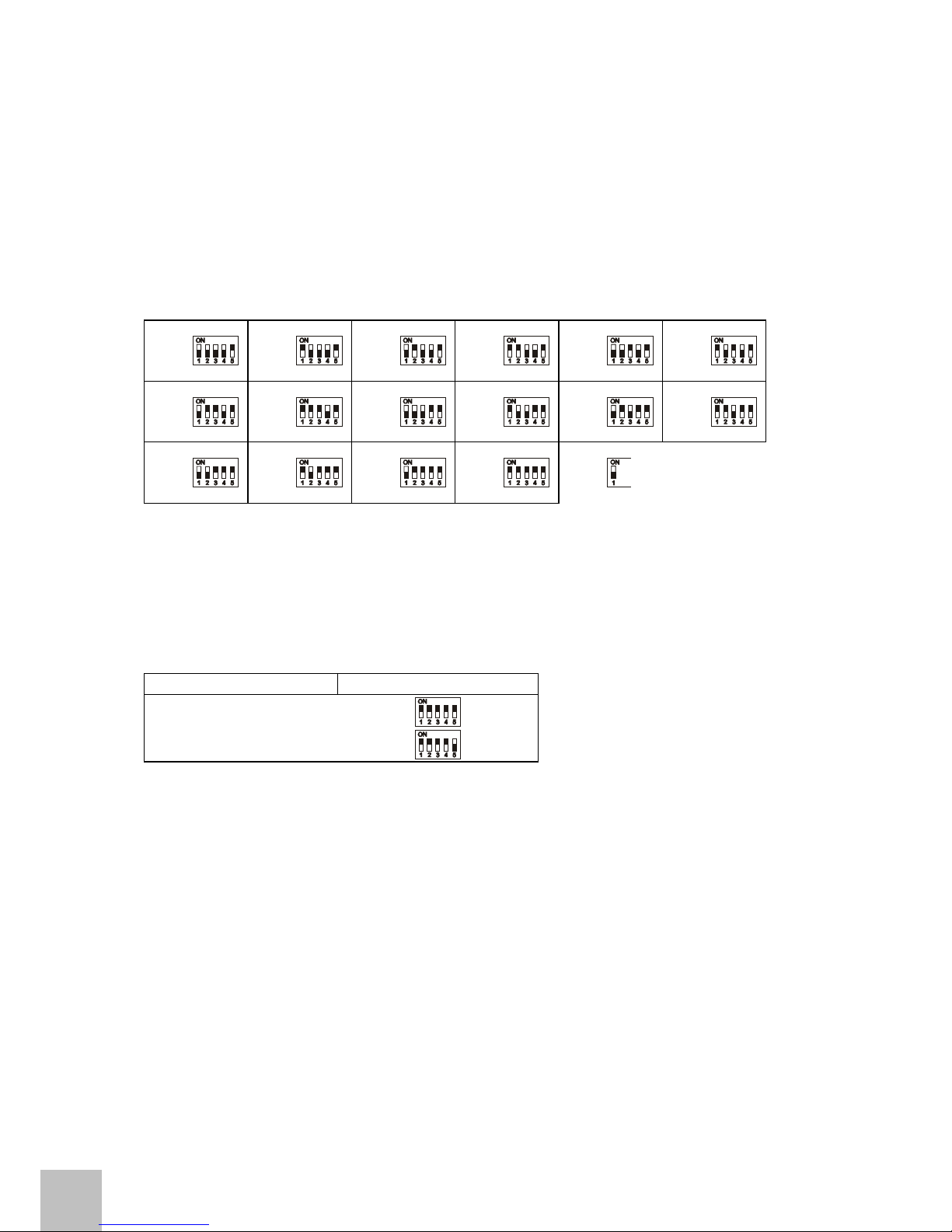
Each hands-free speakerphone in the system gets a number between 1 and 16. This
address is set by means of four out of the five dipswitches.
Chart 3 shows the respective position of the switches 1 - 4.
F1
F2
F3
F4
F5
F6
F7
F8
F9
F10
F11
F12
F13
F14
F15
F16
Schalter in
Stellung ON
chart 3
4.2 Delaying the alarm button (prevention of misuse)
By means of the fifth dipswitch the delaying time for the alarm button is set. This
means that the alarm button must be pressed at least for this period of time to be
activated.
delaying time position of switch no. 5
0,5 sec
2 sec
chart 4
4.3 Volume
Each hands-free speakerphone has a volume control. To prevent whistling sounds
that could arise during communication a control is integrated which automatically
reduces the volume if there are feedbacks. For perfect function of this control the
adjusted volume must not exceed a certain level. This level is determined by the
acoustics inside the car.
When installing the hands-free speakerphone special care should be taken to the
position. Loudspeaker and microphone holes should be as close to the faceplate as
possible.
If the volume is too high the speech transmission gets unintelligible. In this case
please turn back the volume.
Page 11
© SCHAEFER GmbH Installation Instructions FPM 32
11
5. Specifications
• supply voltage 12..24 Volt DC (±15 %)
• no. of participants max. 16 handsets
max. 16 hands-free speakerphones
• distance between devices max. 1 000 m
• power consumption handset about 5-7 mA (standby)
(per device) about 40 mA (active)
about 60 mA (communication)
LMK about 6-8 mA (standby)
(per device) about 40 mA (active)
about 100 mA (communication)
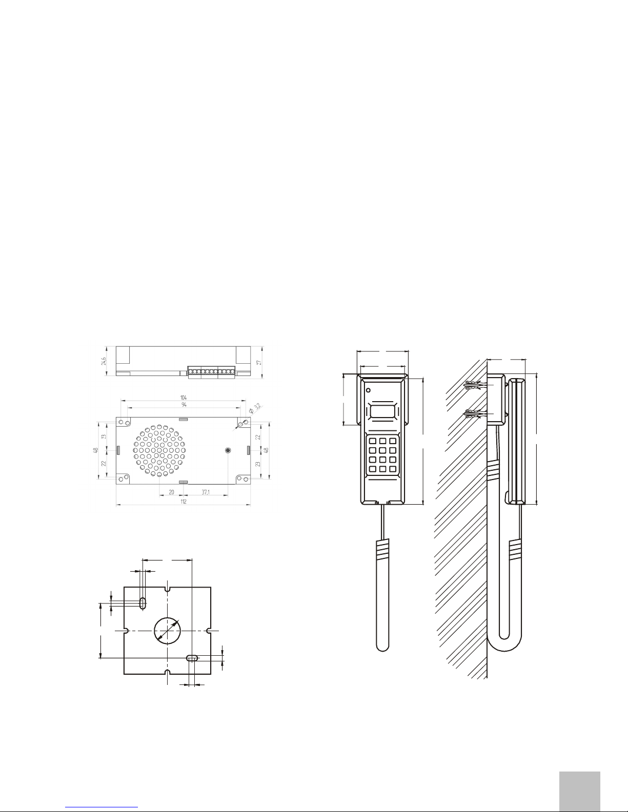
• dimensions (mm) see drawings below
hands-free speakerphone handset
fixing plate for handset
36
ø
1
9
4
4
4
4
4
0
7
2
1
7
6
1
8
2
72
61
54
 Loading...