

57" Fiberglass Exhaust Fan with Cone
Operators Manual
Fiberglass Exhaust Fan
IMPORTANT: READ AND SAVE THESE INSTRUCTIONS
Read all instructions carefully before attempting to assemble, install, operate or service the product described.
Failure to comply with instructions could result in personal injury and/or property damage.
Using this product for any other purpose than it was intended, or not within the operating specifications in this
manual will void the warranty and may cause damage to the fan or serious injury to personnel.
WARNING - TO REDUCE THE RISK OF FIRE OR ELECTRIC SHOCK:
!
• Do not expose fan to water or rain.
• The power source must conform to the electrical requirements of the fan. Consult your local electrician before wiring and
follow all national, state, and local electrical codes.
• Disconnect all power before performing maintenance.
• DO NOT use a variable speed control device, unless your fan has been equipped with a VFD-compatible motor.
GENERAL SAFETY
• This fan is intended for general use only. Do not use near hazardous or explosive materials or vapors.
• Never insert fingers or any other objects into the fan when in operation.
• Use of an OSHA complying guard if within seven feet of floor is recommended.
• Use of a guard, shutter or hardware cloth if above seven feet of floor is recommended.
• Carefully read all safety messages in this manual and on your equipment safety decals.
Follow recommended precautions and safe operating practices.
1
SCFA-408
KEEP THIS MANUAL IN A CLEAN, DRY PLACE FOR FUTURE REFERENCE.
All information, illustrations and specifications in this manual are based on the latest product information available at the time of
printing. Product specifications subject to change. We reserve the right to make changes at any time without notice.
If you need replacement parts, please contact your dealer. Take special care when ordering replacement blades, pulleys,
motors and belts to ensure you get the proper configuration for your fan. If you do not have that information, please call
Schaefer Ventilation Equipment at 800-779-3267 for assistance.
SAFETY INFORMATION
Warning and danger decals have been placed on the equipment to warn of potentially
dangerous situations. Care should be taken to keep this information intact and easy to
read at all times. Replace missing or damaged safety decals immediately.
Safety decal locations
IMPORTANT!
Schaefer Ventilation Equipment strongly recommends that a good alarm system be
installed in confinement buildings to warn of power failure and high temperature.
Schaefer also recommends that an alternate power source be available for
confinement buildings in case of power failure.
INSTALLATION INFORMATION
Schaefer 57” exhaust fans are shipped fully assembled* and only need to be fastened to the wall framework with suitable
fasteners for your facility (not supplied). Fasteners should be grade 2 or better, and corrosion resistant. *Discharge cone and
guard are shipped loose for on-site installation.
• Build wall framing to the required wall opening dimensions and specifications illustrated below.
• Framing methods may vary due to building design or local codes.
• It is the customers responsibility to install the fan correctly and verify proper operation.
• If blade clearance is less than specified, proper corrections must be made before running the fan.
• Failure to follow these guidelines may affect performance, cause potential damage, and will void the warranty.
The following conditions must be avoided to prevent deforming the fan housing.
• Undersized framework rough-in opening
• Out-of-square framework rough-in opening
• Out-of-plane framework mounting surface
• Fan housing resting on framework
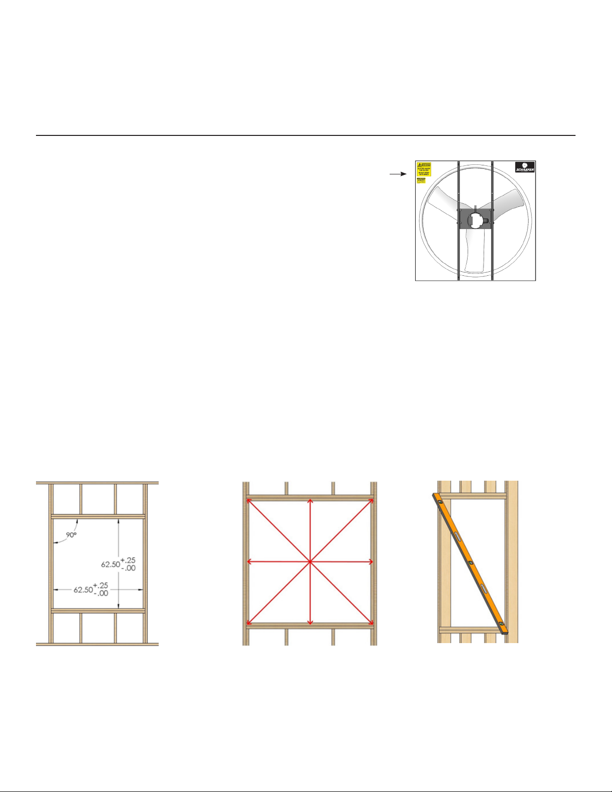
Rough-In Opening Dimensions
Standard 2x6 wall construction
Rough-in framing tolerance: +1/4” / -0”
Frame must be square within 1/4” in the
vertical and horizontal directions shown.
Check for square: the difference between
diagonal measurements must be 3/8” or less.
Planar Requirements
The framework mounting surfaces should be flat within 1/8” across all
directions as shown. If the framework is out of plane, use appropriate
shims or furring strips to correct the issue.
2
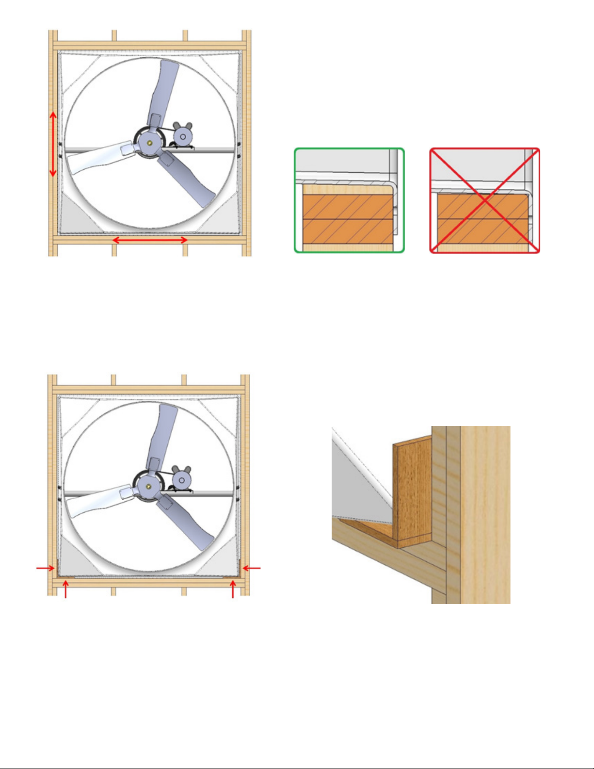
Correct posion Wrong posion
Center fan housing in opening
Center the fan housing in the opening left–right and
up-down before fastening. Use shim boards during the
installation process to maintain fan position.
Mounting Flange contact detail
Typical section view of all four sides with proper clearance.
Only the fan mounting flange should be in contact with the
framework. The fan housing should not be resting on the
bottom frame board.
Temporary shims for centering fan
Use 1/2” thick shim boards in both lower corners during
fan installation. Remove these boards after the fan is
permanently fastened to framework.
Boards that are wider than the frame are
easier to grab hold of and remove.
3

Fasten along top edge 1st
Fasten down
sides 2nd
Fasten down
sides 2nd
Recommended fastening procedure
1. Fasten the top edge of the fan.
Remove any temporary shim boards after the top
edge is fastened.
2. Fasten the sides, starting at the top and working
down both sides together.
3. Fasten the bottom edge of the fan.
Fasten along bottom edge 3rd
Check blade clearance
Slowly turn fan blade and verify minimum blade
clearance of 3/16” through the full rotation.
2. Flashing should be attached across the top of the fan on the outside of the building. Caulking can be used on the sides of the
fan housing to assure a tight seal.
3. Once the unit has been securely fastened to the wall, the fan is ready to be wired.
POWERING THE FAN:
CAUTION:
!
ALL ELECTRICAL WORK SHOULD BE COMPLETED BY QUALIFIED ELECTRICIAN AND MEET ALL NATIONAL,
STATE AND LOCAL CODES.
INSTRUCTIONS FOR WIRING
• Wiring should only be done by a trained electrician to prevent injury or death.
• Configure internal wires to match supply voltage and wire according to motor
nameplate. Test to verify correct rotation.
• Many of the electric motors in our fans are reversible. Make sure the fan is rotating
in the proper direction (see BLADE ROTATION ARROW LABEL on the fan housing).
Follow instructions on the motor label to change rotation if necessary.
• Schaefer recommends installing a lockable disconnect switch near each fan.
• Route wire to motor with drip loop and secure. Drip loop will drain accumulated
moisture away from the motor.
• Only permit power to unit when motor cover plate is properly installed to prevent injury.
4
Fan blade rotation direction

SHUTTER INSTALLATION
1. Six (6) shutter latches are supplied with each fan which are used to hold the shutter in place. Position two on the top, two on
the bottom and one on each side.
NOTE: The latches should be positioned with two (2) on the top and two (2) on the bottom. Be sure to use two (2) washers for each
shutter latch (see Figure 1).
Shutter Installation Kit includes:
• Shutter Latches (0TAB58X1A)
• 1/4" Lag Bolts (0LB1420X112HZ)
• 1/4" Flat Washers (0W14STDZ)
Interior of
Building
Shutter Installation
1/4" Lag Bolt
X X
Shutter Latch
Figure 1
Assemble shutter latch
parts as shown.
2 Washers
57" FIBERGLASS CONE EXHAUST FAN
1-PIECE CONE INSTRUCTIONS
Step 1a
insert bolt
through
guard
eyelet.
Step 3a
Insert bolt
through
housing
from inside.
X
X
Step 1b
Install washer
and nylock nut
from cone
side.
Step 2 Lift cone onto top
edge of housing, then ease
onto bottom until fitted
evenly all around.
Step 3b
Install washer
and nylock nut
from cone
side.
X
X
1-Piece Cone Kit includes:
• 1-Cone Section (10090-57EF)
• 1-Cone Guard (10172-57EF)
• 1-Hardware Bag (HDWR-52C)
Tools required:
• #2 Phillips Screwdriver OR Powered
Drill-Driver with #2 Phillips Bit
• 7/16" Combination Wrench
1. Install the cone guard: lay the
cone flat on the ground with the
smaller end down. Lay the guard on
the rim of the cone and insert the
bolts from the hardware bag into the
guard eyelets from the top (guard)
side. Install a washer and a nylock nut
from the bottom (cone) side.
2. After guard is securely attached
to cone, lift cone onto top edge of
housing first and then ease over bottom edge. Note: Because the polyethylene cone will expand and contract
according to temperature, it may be
necessary to warm the cone if the ambient temperature is at 55°F or below.
3. Line up holes in cone and housing. Insert bolts from the inside of the
housing and install a washer and a
nylock nut on the outside. Start tightening hardware at bottom and work
evenly around edge to top.
Exterior of
Building
5

57" FIBERGLASS CONE EXHAUST FAN
2-PIECE CONE INSTRUCTIONS
*NOTE: Installation of the 57" two-piece poly cone should
NOT be attempted by one person alone! This assembly
requires a minimum of two persons to complete.
1) Begin with the fan installed in the building wall, securely
fastened and ready for cone installation.
2-Piece Cone Kit includes:
• 2-Cone Sections (10171-57EF)
• 1-Cone Guard (10172-57EF)
• 1-Hardware Bag (HDWR-57C-2PC)
Tools required:
• #2 Phillips Screwdriver OR Powered Drill-Driver with #2 Phillips Bit
• 7/16" Combination Wrench
• Ratchet Binder Strap - Minimum 16 Ft. Long
2) Position the cone sections with the flange ends facing
up.
4) Insert the 1/4" x 1-1/4" long bolts with flat washer from
the outside and use the locknut and flat washer on the
inside. Do this for the first two locations on the overlap
seams. Do Not Tighten.
3) Overlap the ends fo the cone sections.
5) Hardware in the first two locations on the overlap
seams of the cone should resemble the image above.
6) Install the cone guard on the partially assembled cone. 7) Line up the loops on the cone guards with the holes in
the rim of the cone sections.
6

2-PIECE CONE INSTRUCTIONS continued
8) Install a 1/4" x 1-1/4" long bolt and flat washer at each
cone guard loop location.
10) Once all of the bolts are in place on the guard, pull
the cone sections together as tightly as possible.
9) Place a lock nut and flat washer on each bolt on the rim
of the cone sections. Do Not Tighten.
11) Tighten the bolts in the two outer locations on the
overlap seams of the cone.
12) Tighten the bolts in the cone guard. 13) Turn the cone over.
7

2-PIECE CONE INSTRUCTIONS continued
14) Install hardware in 3rd location on the overlap seams
of the cone using a 1/4" x 1-1/4" long bolt with flat
washer from the outside and use the locknut and flat
washer on the inside. Do Not Tighten.
16) With one person holding the cone in position, install
1/4" x 1-1/2" bolts with flat washers from the inside of
the fan, securing with flat washers and locknuts on the
outside. Start at the top and work evenly around the fan
nozzle. Do Not Tighten the Bolts.
15) Pick up the cone and slide it onto the nozzle of the fan
housing. Use two people to ensure safety. Position the
overlap seams at the top and bottom of the fan (12:00
and 6:00 positions).
17) Install a ratchet binder strap (minimum 16 ft. long) and
draw the cone sections snug around the fan nozzle.
18) The image above shows the ratchet binder strap in
the proper position.
19) Tighten all bolts securely. 20) Tighten bolts in 3rd location on both
overlap seams.
8
21) Remove the ratchet binder strap from cone.
Cone assembly is complete.

MAINTENANCE
The fan you have purchased is built with heavy duty components, designed to give you many years of worry-free performance.
Like anything else that is mechanical, your fan will require a small amount of periodic maintenance to assure maximum efficiency.
!
Disconnect power before cleaning or maintaining your fan in order to prevent serious injury or death.
PERFORM EVERY 6 MONTHS
Clean motor, fan blade and guard option
• Service and repair of fan should only be completed by a qualified technician.
• Use an air hose to remove dust.
• Use a damp cloth to remove grime and grease.
• PRESSURE WASHING WILL VOID WARRANTY.
• Do not use harsh chemicals or cleaners to clean any part of the fan.
• Sealed motor bearings are pre-lubricated and do not require servicing.
CAUTION: Fasteners may loosen over time. It is important to check and tighten fasteners frequently.
CAUTION: Inspect fan components and fasteners frequently for corrosion. Replace any corroded fasteners or parts.
SET SCREW TIGHTENING SCHEDULE
1. Before initial operation of the fan, tighten set screws according to the procedure outlined below.
2. After 500 operating hours or three months, whichever comes first, tighten set screws to the full recommended torque.
3. At least once a year, tighten set screws to the full recommended torque.
Table 1. Recommended
PROCEDURE FOR TIGHTENING SET SCREWS IN BEARINGS AND BLADES
ONE SET SCREW APPLICATION
Using a torque wrench, tighten the set screw to the full torque recommended in Table 1.
TWO SET SCREW APPLICATION
1. Using a torque wrench, tighten the one set screw to half of the torque recommended in Table 1.
2. Tighten the second set screw to the full recommended torque.
3. Tighten the first set screw to the full recommended torque.
Tightening Torque for
Set Screws
Set
screw
diameter
#10 35
1/4 80
5/16 120
3/8 240
Torque
(in-lbs)
BELT DRIVE FANS ONLY
PERFORM EVERY 6 MONTHS
CHECK BELT TENSION
• Belt tension should be just tight enough to minimize slipping, but not so tight as to cause
premature wear. Correct tension is 3/4" deflect at 10 lbs. of force.
• When a new belt is installed, the indicator on the idler base should line up between
the third and fourth notch on the idler arm.
• To increase tension from idler arm, while holding the hex on the face of the idler, loosen
the 3/8" attaching bolt. Release the large hex and rotate the idler base counter-clockwise.
Now hold the large hex stationary and re-tighten the 3/8" attaching bolt, making sure
the larger hex does not turn. To decrease belt tension, rotate base clockwise.
After adjustment, verify idler arm moves freely.
EVERY 800 HOURS OF OPERATION
GREASE THE BEARINGS
• While slowly turning the bearing,
use 1-2 shots of a lithium base NLGI
#2 grease from a hand operated
grease gun to adequately fill the
bearing 30-50% full.
9
Note: Verify that the grease seals on
both sides of the bearing are intact and
not showing signs of displacement or
deformation once greasing activities
have been completed. Over greasing
bearings will cause premature failure of
bearings if seals are compromised.
3/8" bolt
Large hex
3rd
base indicator
4th

TROUBLESHOOTING
SYMPTOM POSSIBLE CAUSES CORRECTIVE ACTION
Fan not operating
Insufficient airflow
Excessive fan noise
Excessive vibration
Fan does not turn off
1. Improper wiring
2. Fan control set above room temperature
3. Blown fuse or tripped breaker
4. Fan blade contacting fan
5. Fan control defective
6. Motor defective
1. Shutter jammed
2. Guard, shutter, fan blade dirty
3. Fan blade facing wrong direction
4. Incorrect belt tension
1. Fan blade contacting fan panel
2. Motor bearing defective
1. Motor loose in mount
2. Fan blade damaged
3. Motor shaft bent
4. Fan shaft bent
5. Pillow block bearings defective
1. Thermostat set incorrectly
2. Control set for continuous operation
1. Ensure wiring is done correctly
2. Set to a lower temperature
3. Replace fuse or reset breaker
4. Realign fan blade in fan housing
5. Repair or replace control
6. Repair or replace motor
1. Clean shutter and fan housing
2. Clean guard, shutter and fan blade
3. Orient fan blade correctly
4. See Maintenance section
1. Realign fan blade in fan housing
2. Repair or replace motor
1. Tighten fasteners
2. Replace fan blade
3. Repair or replace motor
4. Replace fan shaft
5. Replace pillow block bearings
1. Set to the desired temperature
2. Set fan control correctly
WARRANTY
Schaefer Limited Warranty Policy
Schaefer Ventilation Equipment, LLC (SVE) provides the following limited warranty from the date of invoice to the initial purchaser of our
products or to its customer with a dated proof of purchase:
Two-year coverage (unless otherwise indicated below) applies to all products, components and assemblies provided by SVE that prove to be defective in material or workmanship. Any such defective product will be repaired or replaced at SVE’s option, with the defective product or component
returned-upon approval, to SVE, F.O.B Sauk Rapids, Minnesota. This warranty does not cover: failure, damage or malfunction as a result of: Improper
installation or installation not in accordance with installation instructions. Operating conditions that vary from SVE’s operating instructions. Misuse,
abuse, negligence, alteration, or accident. Transporting the product. Improper operation or lack of appropriate or regular maintenance of the product.
Loss of time, inconvenience, loss of use of the product or other consequential or incidental damages. Parts that need replacement due to normal wear
and tear. Superficial or cosmetic rust or corrosion. Any product whose name plate has been removed.
Full warranty statement may be printed or downloaded from www.schaeferventilation.com
sales@schaeferventilation.com • www.schaeferventilation.com • 320.251.8696
©2016 Schaefer Ventilation Equipment. All rights reserved.
10
 Loading...