

Page 1

Important Safety Instructions
1. Please read these instructions thoroughly.
2. Please keep this guide for future use.
3. Please dis connect the device from the main sup ply before cleaning. Do not us e any liquid or
aerosol spray cleaners. The best for cleaning is a piece of cloth dampened with water.
4. To avoid damage of the device, you should only use accessory parts permitted by the
manufacturer.
5. The device must be protected against mois ture.
6. To setup the device, it must be put in a stable stand position. Tipping it over or dropping it may
cause injuries. Only use safety setup locations and follow the setup instructions of the
manufacturer.
7. The ventilation openings are used for air circulation which protect the device against
overheating.
8. To connect the device, f ollow the connected loa d values of the main supply.
9. Due to electrical safety, t he wall sock et must be equipp ed with a non-fused ear thed conductor
contact.
10. The power cable must be laid i n a way that nob ody may trip over it. Ther e should als o nothing
be resting on the cable.
11. All instructions and warning remarks on the device must be followed.
12. If the device will not be used for a long period of time, you should dis connect it fr om the main
supply to avoid overvolta ge damage.
13. Any objects or li quid should never enter the device via its openings for air circul ation. This
could cause a fire or an electric shock.
14. Do not op en the device ever. For elect rical safety, the devic e shall be opened by authoriz ed
technical service personnel only.
15. If following condi tions occur, the device must be disconnected from the main supply, and it
must be checked by a qualified service center:
a- Power cable or power plug are damaged;
b- Liquid has entered the device;
c- The device was exposed to moisture;
d- The device does not operate according to the user's guide, or you do not achieve any im-
provement with the aid of this guide;
e- The device has dropped and/or the casing is damaged;
f- The device shows obvious si gns of a defect.
16. For repair, only original spare parts or parts in accordance with the original parts may be used.
Use of unsuitable spare parts can cause more damage.
17. Please turn to your service cent er for all questions concerning service and repair to guarantee the
device's performance reliability.
18. The socket outlet must be installed near the equipment to be easily accessible.
i
Page 2
FEDERAL COMMUNICATIONS COMMISSION
(FCC STATEMENT)
This equipment has been tested and found to comply with the limits for a Class B
digital device, pursuant to Part 15 o f the FCC Rules. These limits are designed to
provide reasonable protection against harmful interference in a residential installation. This equipment generates, uses, and can radiate radio frequency energy, and,
if not installed and used in accordance with the instructions, may cause harmful
interference to radio communications. However, there is no guarantee that interference will not occur in a particular installation. If this equipment does cause
harmful interference to radio or television reception, which can be determined by
turning the equipment off and on, the user is encouraged to try to correct the interference by one or more of the following measures:
•= Reorient or relocate the receiving antenna;
•= Increase the separation between the equipment and receiver;
•= Connect the equipment into an outlet on a circuit different from that
to which the receiver is connected;
•= Consult the dealer or an experienced radio/TV technician for help.
Any changes or modifications not expressly approved by the manufacturers may
void the user’s authority to operate this equipment.
A shielded-type power cord is required in order to meet the FCC emission
limits and also to prevent interference to nearby radio and television
reception. It is essential that only the supplied power cord be used.
Use only shielded cables to connect I/O devices to this equipment.
Canadian DOC Notice
For Class B Computing Devices
This Class B digital apparatus meets all requirements of the Canadian InterferenceCausing Equipment Regulat ions.
Cet appareil numérique de la classe B respecte toutes les exigences du Règlement
sur le matériel brouilleur du Canada.
— ii —
Page 3

Table of Contents
Chapter 1 : Introduction ____________________________1
Unpacking __________________________________________ 1
Connecting the Monitor and Stand________________________ 2
Removing the Monitor and Stand ________________________ 2
Choosing a Workstation________________________________ 3
The AC Connection ___________________________________ 4
The Signal Cable Connection____________________________ 4
Monitor Adjustments__________________________________ 5
Chapter 2_________________________________________6
Adjusting the Brightness and Contrast_____________________ 7
The On-Screen Display(OSD)___________________________ 8
Color Temperature Setup______________________________ 10
OSD Window Status _________________________________ 12
Reset and Degauss ___________________________________ 13
Self-Test Screen_____________________________________ 13
Summary of OSD Icons_______________________________ 14
Appendix ________________________________________17
Troubleshooting_____________________________________ 17
— iii —
Page 4

Page 5

CHAPTER 1
Introduction
Congratulations on your purchase of the new high performance 17" Monitor.
Much consideration has gone into the design of the monitor in order to meet your
requirements for full compatibility and versatility as well as quality.
Using state-of-the-art electronics, the monitor can support a resolution of
1280x1024, and the on-screen display allows you to customize the display settings
to suit your individual needs. User display settings will be automatically saved to
memory. In addition, at the touch of a button the user can, at any time, return to the
factory default display settings.
Other ergonomic features include a non-glare screen, tilt and swivel and just two
multi-function display controls that allow you to make all monitor display adjustments.
Unpacking
Please make sure the following items are in the shipping package and found in
good condition:
•= 17" Monitor
•= Tilt and swivel stand
•= P ower cord
•= Signal cable (attached to monitor)
•= This manual
If any of the above are missing or appear damaged, please contact your dealer
immediately.
— 1 —
Page 6
Chapter 1
Getting Started
This chapter covers setting up the monitor and stand in a suitable workplace, and
connecting the power cord and signal cable.
Connecting the Monitor and Stand
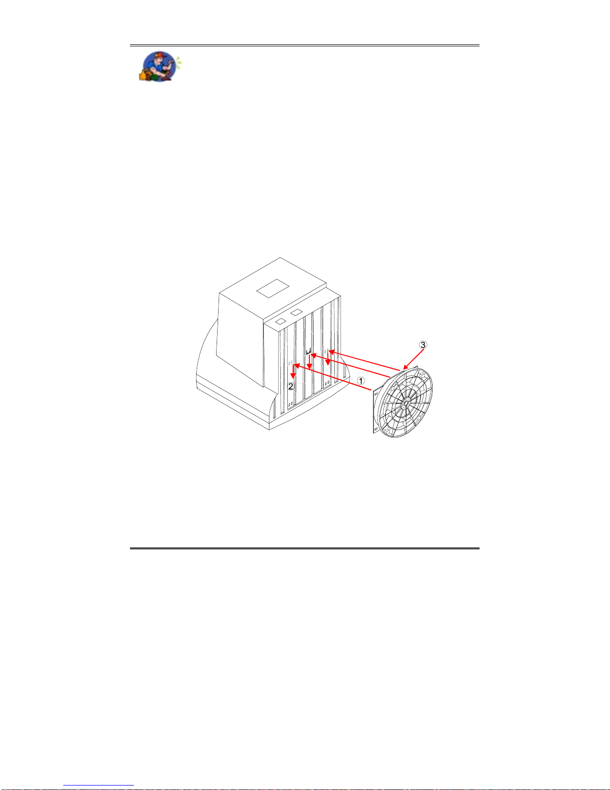
1. Align the stand’s four tabs with the slots in the bottom of the monitor.
2. Slide the stand toward the front of monitor. After insert the tabs into the slots.
3. Push back of swivel ball with angle 45° slowly. You will hear the spring lock
click into place.
Removing the Monitor and Stand
♦= If you need to remove the stand, push the spring lock and slide the
stand away from the monitor.
Figure 1: Monitor and Stand Connection
NOTE:
Special protection on control knobs and LED indicator needs to be taken care while
you place the CRT side of side of monitor downwards. Such concern will escape the
permanent damage occurred on encoder and LED lens from excessive pressure
— 2 —
Page 7
Choosing a Workstation
Keep the following in mind when choosing a work place for the Monitor.
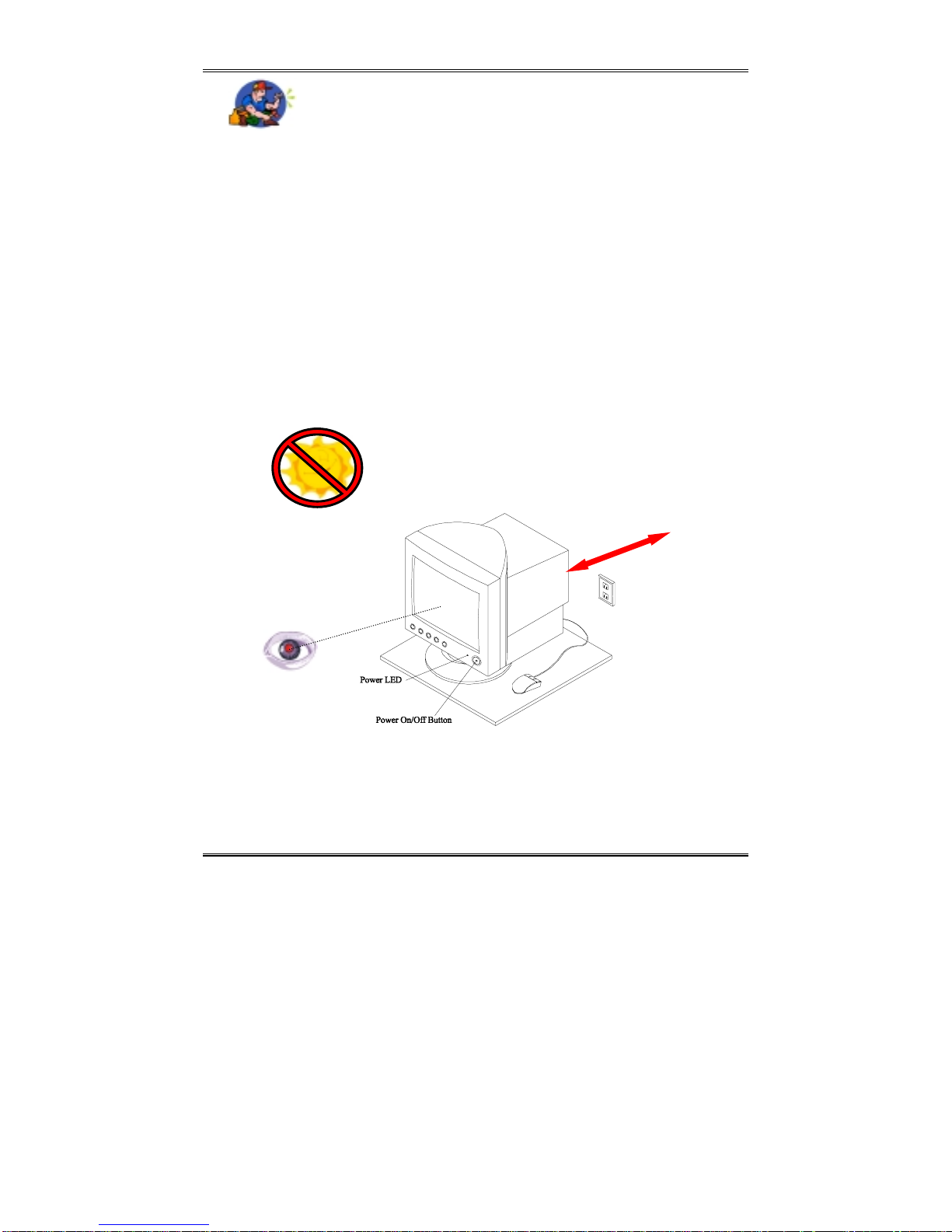
♦= Place the monitor on a stable even surface.
♦= Access to an electrical outlet.
♦= Ensure at least three inches clearance at the rear of the monitor to allow
for sufficient airflow.
♦= Position the Monitor a little above eye-level to reduce neck-strain.
♦= Do not place near a window. Exposing the Monitor to direct sunlight
for extended periods may damage the unit.
♦= You may want to use a desk lamp to adjust the ambient lighting for
your viewing comfort.
♦= A viewing filter is recommended to reduce eye stress and fatigue.
Chapter 1
Figure 2: The Workstation
— 3 —
Page 8
Chapter 1
The AC Connection
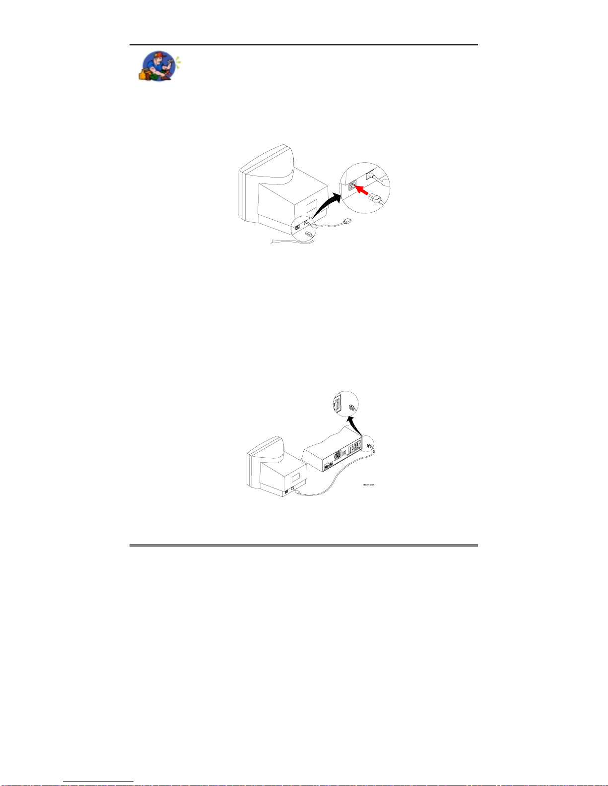
♦= Locate the AC port on the rear of th e mon i t or (refer to Figure 3).
♦= Plug the female end of the AC cord into the AC port.
♦= Plug the male end into the power supply.
Figure 3: Connecting the Power Cord
The Signal Cable Connection
♦= Make sure that the monitor is powered Off. When powered off the Power LED
(see Figure 2) will not be lit.
♦= Locate the VGA port on the rear of the PC. The signal cable has a standard 15-
pin mini D-sub (VGA) connector. If you are having trouble locating the VGA
port, please refer to the documentation, which came with your PC.
♦= Connect the Sign al cable to the PC’s VGA port.
Figure 4: Connecting the Signal Cable
— 4 —
Page 9
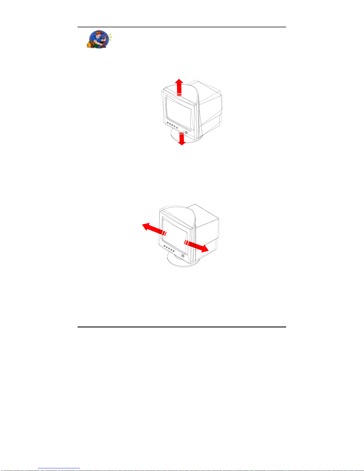
Monitor Adjustments
The monitor is capable of both tilt and swivel adjustments.
Chapter 1
15°
5°
Figure 5: Tilt Adjustment
♦= With the tilt feature, the monitor is capable of vertical adjustments of
+15° to -5°.
♦= The swivel feature allows for horizontal monitor adjustments of +45° to
-45°.
45°
Figure 6: Swivel Adjustment
This concludes Chapter 1. The next chapter covers the on-screen display
(OSD)features.
— 5 —
Page 10
Chapter 2
Figure 7
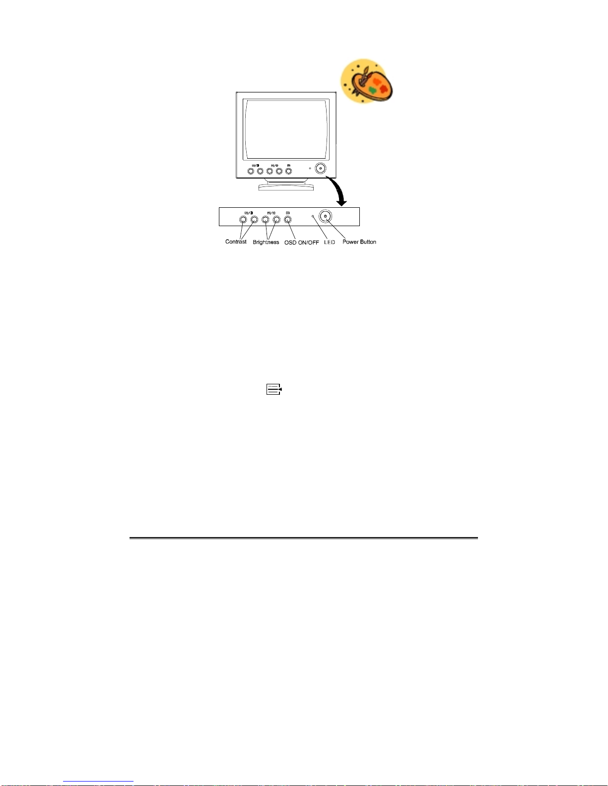
Contrast (and OSD Increase/Decrease) Control
When the OSD Main Men u i s no t en gaged , P r ess the Contrast Control to adjust the display
contrast level to accommodate the ambient lighting conditions of your specific working
environment. When the OSD Main Menu is engaged, Press this control adjusts the displaysetting values.
Brightness (and OSD Function Control) Cont rol
When the OSD Main Menu is not engaged P ress the Brightness Control to adjust the display brightness level. When the OSD Main Menu is engaged. Press the control to rotate
through the Function options.
OSD ON/OFF Control
When this switch is OFF , the other four controls can be used to adjust the monitor’s
Brightness and contrast.
When this switch is ON , the OSD Menu appears and OSD Function control can be used.
Power LED
The Power LED informs you of the monitor’s current operating status. The Power LED
will light Green when the monitor is powered On. In Standby mode the LED lights Amber.
When powered Off the LED is not lit.
Power On/Off Button
Push the Power Button to power the monitor On or Off.
— 6 —
Page 11
Chapter 2
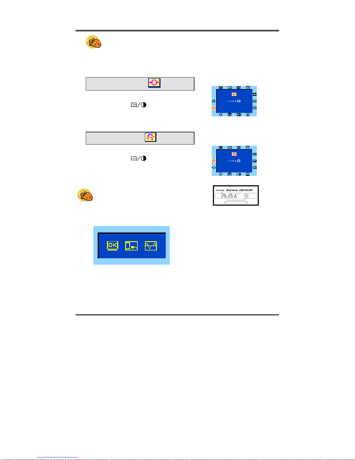
Adjusting the Brightness and Contrast
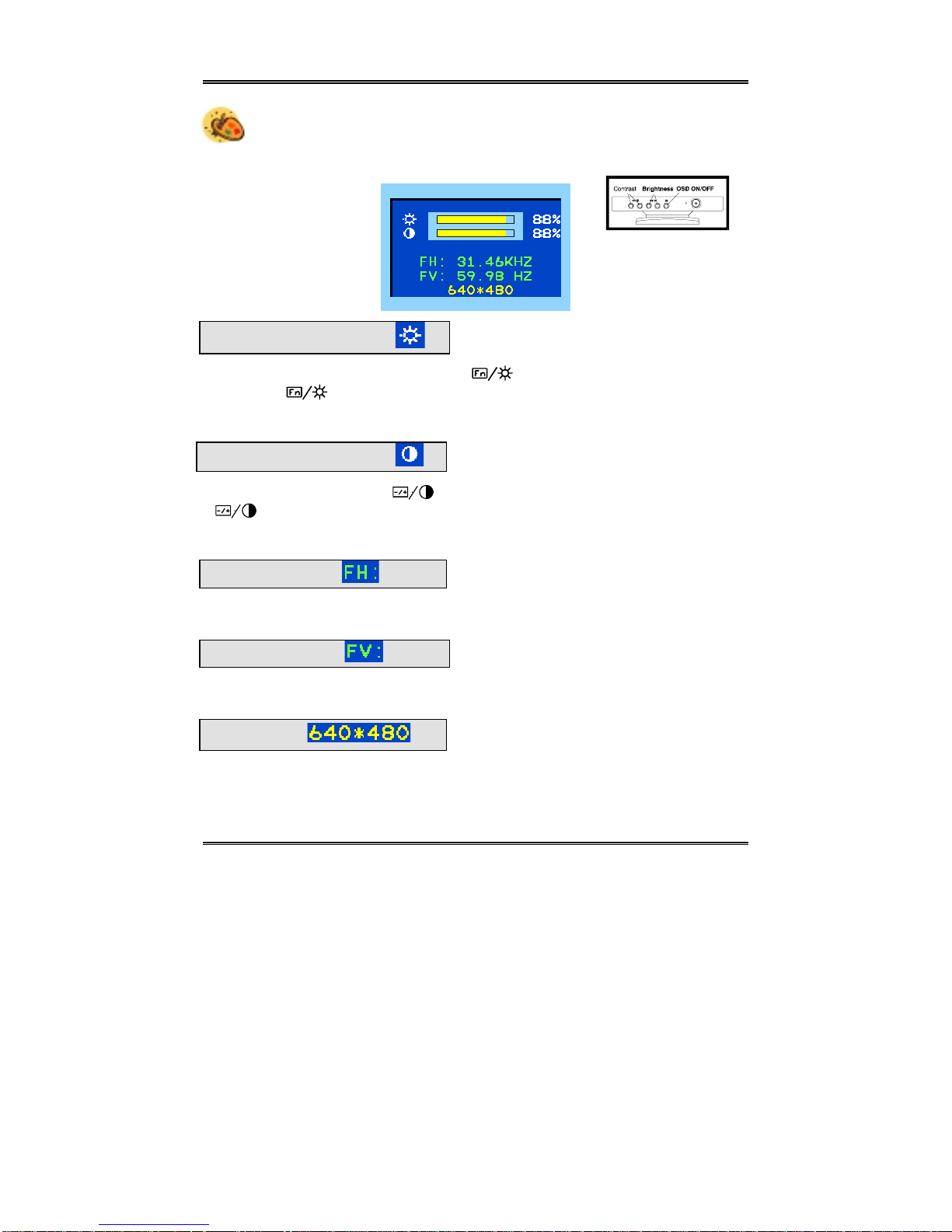
To adjust the contrast and/or brightness, Press the Contrast Control or the
Brightness Control, to call up the following on-screen display:
Brightness
Press the Brightness Control right button ( ) to increase the brightness. Press the
Left button ( ) to decrease the brightness. The brightness level is adjusted from
0% to 100%.
Contrast
Press the Contrast Control ( ) right button to increase the contrast. Press the (
)left button to decrease the contrast. The contrast level is adjusted from 0%
to 100%.
H. Frequency
This field displays the current Horizontal Scan Frequency. Display only field.
V. Frequency
This field displays the current Vertical Refresh Rate. Display only field.
Resolution
This field shows the display resolution to which your mo nitor is set. This is a display
only field. (Note: It only shows the resolution in presetting mode.)
— 7 —
Page 12
Chapter 2
The On-Screen Display (OSD)
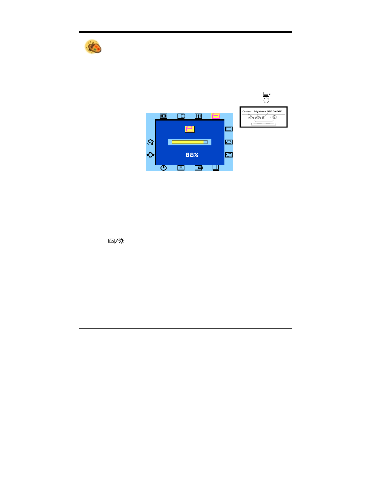
The monitor features an intuitive, on-screen display (OSD), making changes to the
display settings convenient and simple. You can access the OSD any time your PC
is powered On. If the PC is in Standby mode, or is powered Off, the OSD cannot
be accessed.
To access the OSD Main Menu, push theOSD ON/OFF control button ( )
The following screen will appear:
This screen shows the V-Center window allowing you to make a djustments to the
display’s vertical position. Notice the V-Center icon in the window border is highlighted.
Changing Display Settings
Call up the OSD as described above. Now press the Brightness Control button to
scroll thro ugh the ico ns in the window borde r. You ca n press the OSD function or
control( ) button in the window border by rotating the control in the respective
direction.
Once you have selected an icon, use the Contrast Control to adjust the option
value. Press the right button to increase the value; press the left button to decrease
the value
When making changes to the fo llowing settings, a screen similar to the above V-
Center window will appear on your monitor screen.
— 8 —
Page 13
Chapter 2
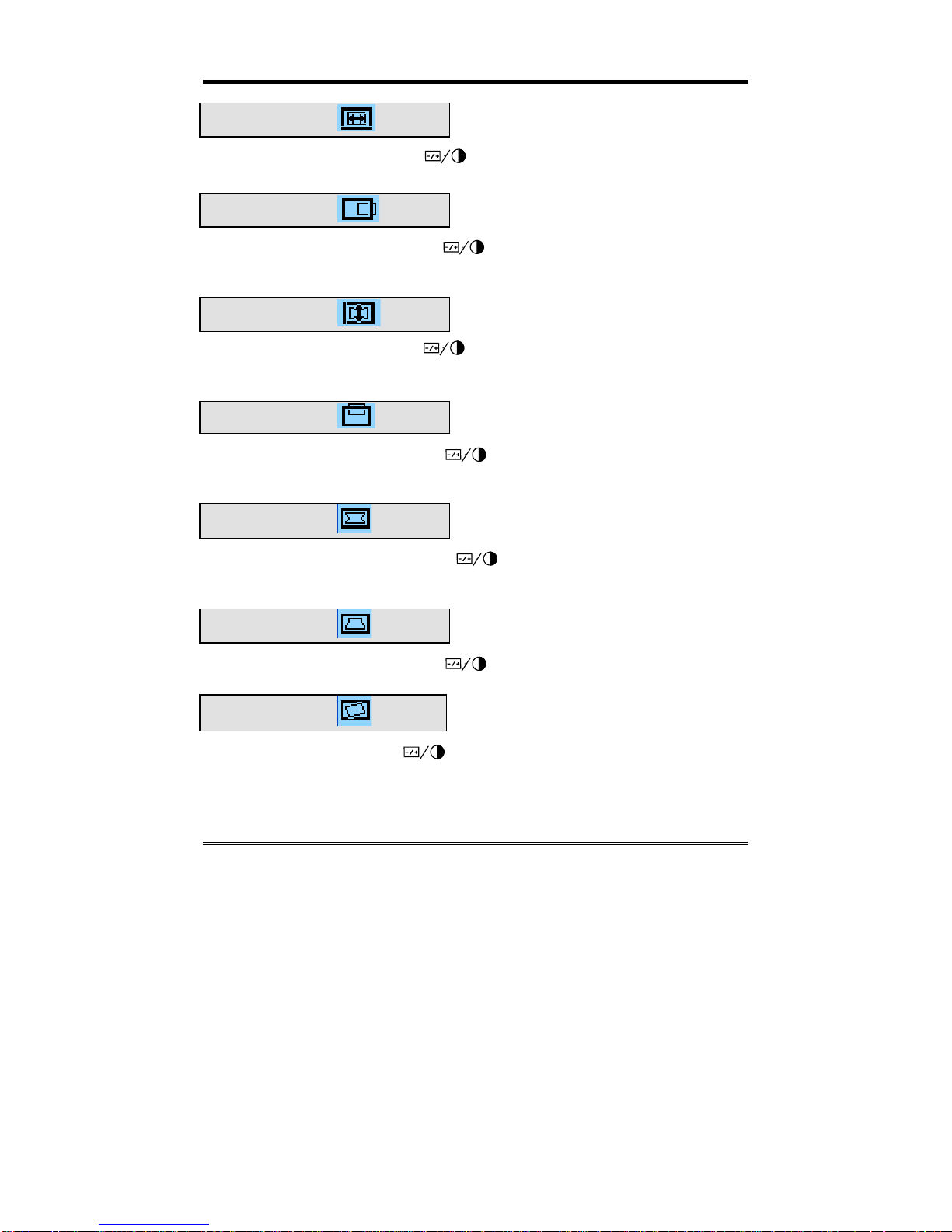
H-Size
Scroll to the H-Size icon. Press the button to adjust the horizontal size of the
display.
H-Center
Scroll to the H-Center icon. Press the button to position the display along the
horizontal axis of the screen.
V-Size
Scroll to the V-Size icon. Press the button to adjust the vertical size of the
display.
V-Center
Scroll to the V-Center icon. Press the button to position the display along the
vertical axis of the screen.
Pincushion
Scroll to the Pincushion icon. Press the button to adjust pincushion or barrel
distortion.
Trapezoid
Scroll to the Trapezoid icon. Press the button to adjust trapezoid distortion.
Tilt
Scroll to the Tilt icon. Press the button to adjust display tilt.
— 9 —
Page 14
Chapter 2
Color Temperature Setup
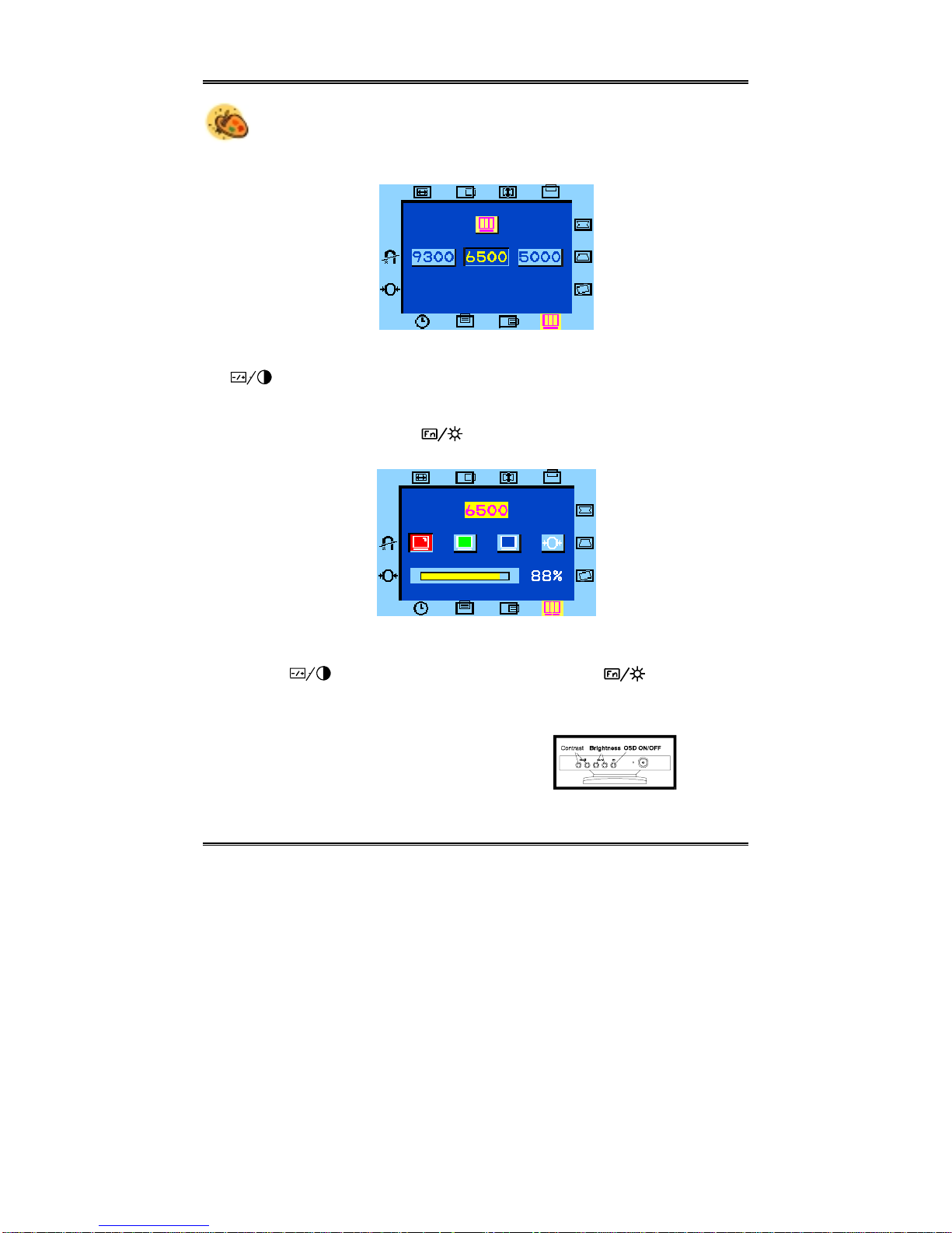
To access the Color setup menu, selet to the Display Color Se tting icon. The
following screen appears:
This screen allows you to select a color temperature for your monitor. Press the
button to select the desired option. The available options are:
♦= 9300 ♦ 6500 ♦ 5000
Press the Brightness function ( ) Control The following RGB Gain window
will appear:
From this window you can make changes to the display’s Red, Green and Blue
gain. Press the Brightness Control to scroll through the options; change values
using the button; after making changes, Press the will enter your
changes, and move to the next icon.
Values for the Red, Green or Blue Gain are displayed from 0% to 100%.
— 10 —
Page 15
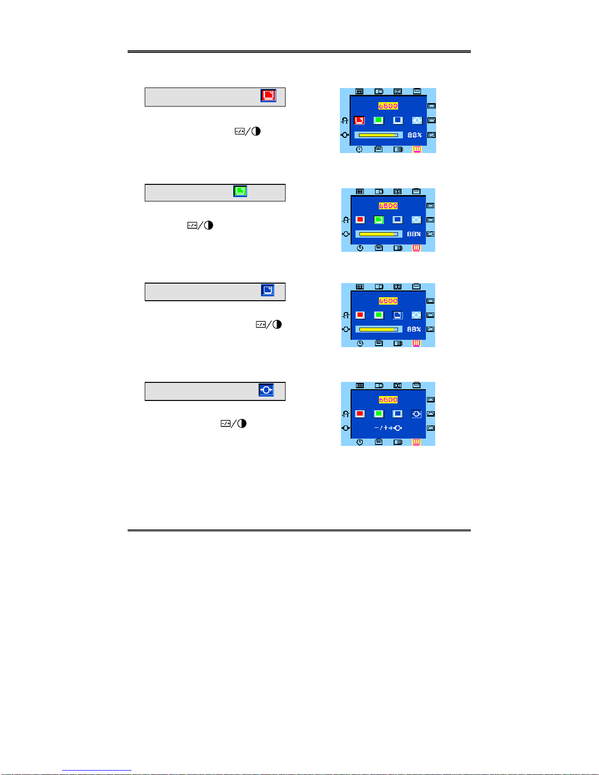
Red Gain
Scroll to the Red Gain icon. Press
the Contrast Contro l to
adjust the red gain for your
display.
Green Gain
Scroll to the Green Gain icon.
Press the Contrast Control
to adjust the green gain for yo ur
display.
Blue Gain
Scroll to the Blue Gain icon.
Press the Contrast Control
to adjust the blue gain for your
display.
Chapter 2
Reset
Scroll to the Reset icon. Press the
Contrast Control to reset
all three gain values to the default
settings. The OSD window will
close.
— 11 —
Page 16
Chapter 2
OSD Window Status
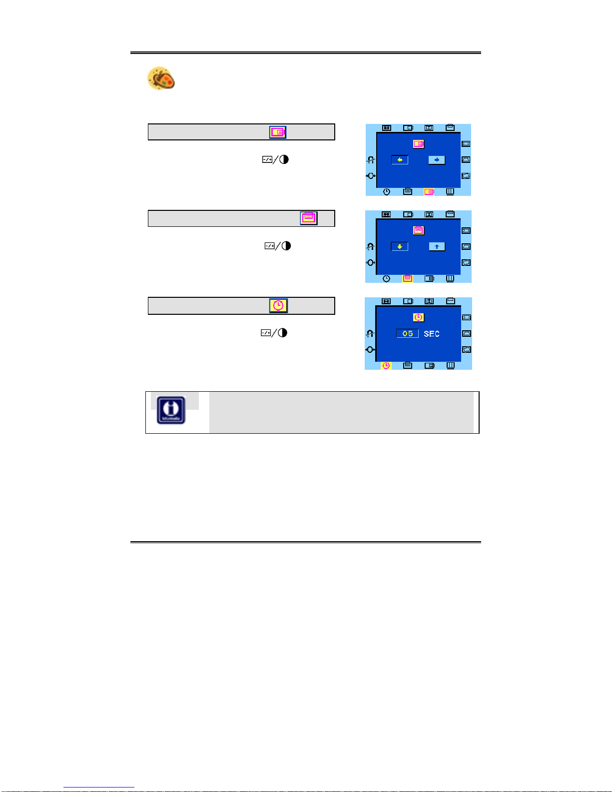
The OSD Window status icons allow you to adjust the position of the
OSD window on your screen. You can also set the time that the OSD window will
be displayed on the screen.
OSD Horizontal Position
Scroll to the OSD Horizontal Position icon.
Press the Contrast Control to adjust
the horizontal position of the OSD on the
screen.
OSD Vertical Position
Scroll to the OSD Vertical Position icon.
Press the Contrast Control to adjust
the vertical position of the OSD on the
screen.
OSD Display Close Time
Scroll to the OSD Display Close Time icon.
Press the Contrast Control to set the
amount of time that elapses before the OSD
closes. Countdown can be set from 5 to 60
seconds.
Don’t be rushed when changing display settings: The Display
Close Time does not begin countdown while you are making
display adjustments.
— 12 —
Page 17
Chapter 2
Reset and Degauss
The Reset All option allows you to reset all display settings to their default values.
Use the Degauss option to remove unwanted magnetism from the monitor’s CRT.
Reset All
Scroll to the Reset All icon. Press the
Contrast Control to reset all display
options. If you do not wish to reset all
display options, press the OSD ON/OFF
Control to close the OSD window.
Degauss
Scroll to the Degauss icon. Press the
Contrast Control to degauss the
CRT. If you do not wish to degauss the
CRT, press the OSD ON/OFF Co ntrol to
close the OSD window.
Self-Test Screen
When the monitor is powered On, but there is no video signal, the following selftest screen will appear.
This screen indicates the monitor itself
is OK. If this screen appears, it is possible that the monitor’s VGA cable is
not connected properly to your computer’s VGA port Check the connection.
If the VGA cable is properly connected but the monitor screen is blank, (i.e., there
is no picture and none of the above icons appear), then there may be a problem
with the monitor.
— 13 —
Page 18
Chapter 2
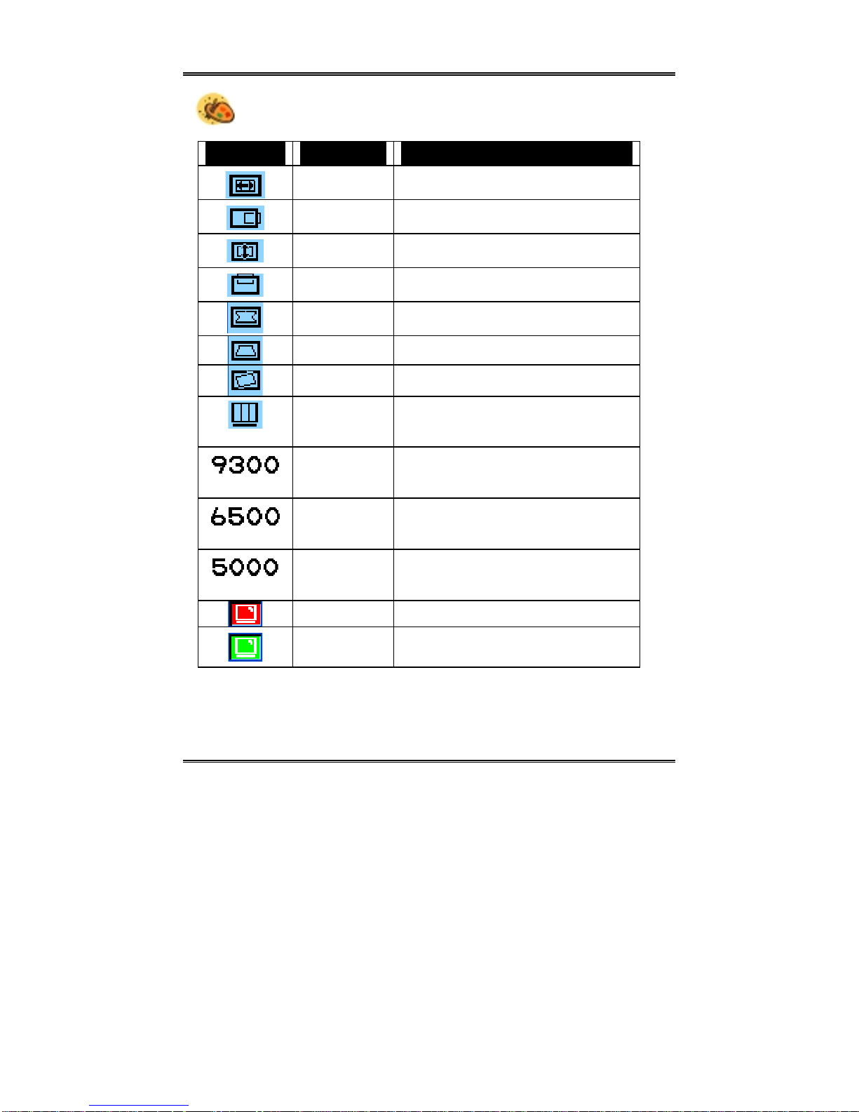
Summary of OSD Icons
Icon Function Description
H-Size Use this option to adjust the horizontal size of
H-Center Use this option to position the display along
V-Size Use this option to adjust the vertical size of
V-Center Use this option to position the display along
Pincushion Use this option to adjust pincushion or barrel
Trapezoid Use this option to adjust trapezoid distortion.
Tilt Use this option to adjust image tilt.
Display Color
Setting
CIE coordinate
9300° Color
Temperature
CIE coordinate
6500° Color
Temperature
CIE coordinate
5000° Color
Temperature
Red Gain Use this option to adjust the red gain.
Green Gain Use this option to adjust the green gain.
the display.
the horizontal axis of the screen.
the display.
the vertical axis of the screen.
distortion.
Use this option to adjust the color setup.
Refer to The Color Setup in the following
section for more information.
Select this option to set the monitor for the
CIE coordinate 9300° color temperature.
Select this option to set the monitor for the
CIE coordinate 6500° color temperature.
Select this option to set the monitor for the
CIE coordinate 5000° color temperature.
— 14 —
Page 19

Icon Function Description
Blue Gain Use this option to adjust the blue gain.
Reset This option allows you to reset the three color
settings to the default value.
Chapter 2
OSD Horizontal
Position
OSD Vertical
Position
OSD Display
Close Time
Reset All Use this option to reset all display settings to their
Degauss The Degauss option removes unwanted magnetism
This concludes Chapter 2. The following appendix provides details on your monitor’s technical specifications. You will also find tips on troubleshooting any
problems you may run into.
Select this option to adjust the horizontal position of
the OSD on the screen.
Select this option to adjust the vertical position of the
OSD on the screen.
Use this option to set the amount of time that elapses
before the OSD closes.
default values.
from the monitor’s CRT.
— 15 —
Page 20
APPENDIX A
Troubleshooting
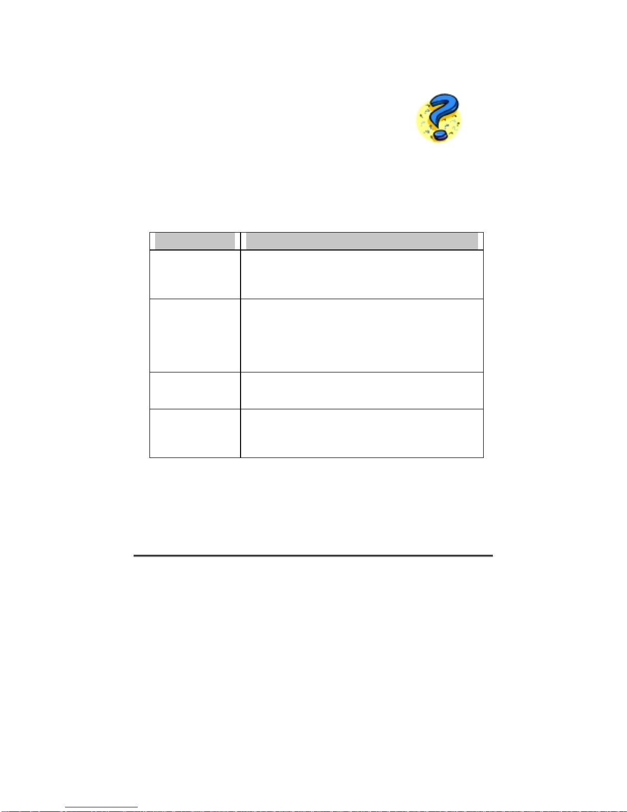
This section will try to anticipate potential problems that you may encounter in the
day-to-day use of your monitor. Included in this section is information which
should help solve these problems for you. If after trying the suggested solutions,
your monitor’s symptom remains the same, contact your authorized service center.
Symptoms Solution
The monitor is
switched on, but the
power LED is not lit.
The LED light is on
but there is no
display on the
monitor’s screen.
The display image is
either dangling or
unstable.
The picture is
bouncing or a wave
pattern is present in
the display.
Check to make sure that the power cord is properly
connected. If the monitor is plugged into a powered extension
cord or a surge protector, make sure that extension cord or
the surge protector is turned on
Make sure that the computer’s switch is in the “On” position.
Make sure that the video cable’s D-shaped connector is
properly connected to the video adapter port on the back of
the PC.
Check to make sure that the brightness and contrast control
are not turned to their dimmest position.
Make sure that the video cable’s D-shaped connector is
properly connected to the video adapter port on the back of
the PC.
Move any electrical devices away from the monitor which may
cause display interference. Please refer to the FCC statement
at the beginning of the manual for more details on display
interference.
— 16 —
 Loading...