

Page 1

State: 2010-03-01
Vers. no.: 1.10
Annex no. 5
Functional Description /
User Manual
m. dudde hochfrequenz-technik Rottland 5a D-51429 Bergisch Gladbach/ Germany Tel. +49 2207-96890 Fax +49 2207 968920
Page 2

Manual and Specification
SIR-2010 ( STK-2010 )
13.56 MHz Midrange Reader (-Modul)
Project:
SIR-2010 ( STK-2010 )
Creation date
22.03.2011
Last date printed
07.04.2011 15
Path:
p:\sir-2010\doc\spezifikation (manual)\manual & specification\sir-2010_manual_engl._v.0.01.doc
Document number
0000.0000.2010
Project manager
M. Radermacher Jürgen Kalbitzer Rudolf Schmitz
System version
Author
M. Radermacher
0.0.0 0.01
Revised
11.04.2011
Number of pages
Author
M.Radermacher
Development manager
Managing director
Document version
© scemtec transponder technology GmbH · Gewerbeparkstr. 20 · D-51580 Reichshof
Page 3

Manual and Specification
SIR-2010 ( STK-2010 )
Table of Contents
1 Introduction___________________________________________________________________ 3
2 System Description ____________________________________________________________ 4
3 Block Diagram_________________________________________________________________ 5
4 Operating Modes ______________________________________________________________ 5
4.1 Self-Test (Diagnosis) and STAND-BY Operation_____________________________________ 5
4.2 Reading / Writing Tags_________________________________________________________ 5
4.3 EAS Antitheft ________________________________________________________________6
5 Hardware _____________________________________________________________________ 6
5.1 Voltage Supply_______________________________________________________________6
5.2 HF Unit_____________________________________________________________________6
5.3 External Antenna _____________________________________________________________ 6
5.3.1
Antenna connector (SMA-connector location) ___________________________ 7
5.4 Digital unit___________________________________________________________________7
5.4.1
Processor _______________________________________________________ 7
5.4.2
Memory_________________________________________________________ 7
5.5 Interfaces ___________________________________________________________________ 7
5.5.1
Location of interface-connectors _____________________________________ 7
5.5.2
Ethernet ________________________________________________________ 7
5.5.3
USB ___________________________________________________________ 7
6 Software______________________________________________________________________ 8
6.1 Firmware for the SIR-2010 Midrange Reader System_________________________________ 8
6.2 STX / ETX Interface Protocol____________________________________________________8
6.3 List of supported STX/ETX Commands____________________________________________8
7 Diagnosis____________________________________________________________________ 12
7.1 Self-Test (POST) ____________________________________________________________ 12
7.2 LEDs______________________________________________________________________12
7.2.1
External Diagnosis LEDs __________________________________________ 12
7.3 Label / Type Plate____________________________________________________________12
8 Mechanical Data / Housing _____________________________________________________ 12
9 Electrical Data________________________________________________________________ 13
10 Conformity___________________________________________________________________ 13
10.1 CE Conformity ______________________________________________________________ 13
10.2 FCC Conformity: Information for USA____________________________________________ 14
11 Delivery Scope / Optional Equipment and Accessories______________________________14
11.1 Manual, CD-ROM, Test Software, Protocol Description ______________________________14
11.2 Optional Accessories / External Antenna(s)________________________________________ 14
12 Datasheet____________________________________________________________________ 14
13 Related Documents / Document History __________________________________________15
13.1 Document History____________________________________________________________ 15
Document No. SIR-2010 Version: 0.01 Page 2 of 15
Page 4

Manual and Specification
SIR-2010 ( STK-2010 )
1 Introduction
As with all electronic systems, the system described hereafter may also not be used for any
applications critical for maintaining safety. This means, the products may not used in life
support applications or any other life critical applications that could involve potential risk of
death, personal injury or severe property or environmental damage.
The user/operator is solely responsible for any damages resulting from an improper or
unintended utilization of the system.
scemtec Transponder Technology GmbH (STT) reserves the right to make changes or to discontinue its
products or services at any time without notice.
STT takes no responsibility for customer applications, products, or performance relating to systems or
applications incorporating with STT products.
STT assumes no liability and is not responsible for infringement of patents and/or any other intellectual
or industrial property rights of third parties, which may result from assistance provided by STT.
The Windows® logo is a registered trademark of Microsoft Corp.
All other products mentioned in this document might be brands or brand names of the different
suppliers.
Copyright © 2011 scemtec Transponder Technology GmbH (STT)
General:
As this technology is based on radio frequency, one must exercise the following operational and
mounting instructions to achieve best operation:
• Metal affects radio signals. Normally the antenna has to be as far away as possible from any
metal object and it’s damping influence on the magnetic field. Only this leads to the best
distribution of the magnetic field in the reading range. Very important as well is not to have “short
circuits”, in the vicinity of the antenna, damping the magnetic field. A “short circuit” is any metal
near the antenna, building a “metallic ring”, so that currents introduced by the RF-field can flow,
destroying the energy needed for the tag to operate.
• Care must be exercised to reduce or eliminate unwanted signals (so called interference or
noise) from external sources. The reading range may be reduced by following noise sources:
• portable two way radio
• cellular phones
• switching power supplies
• computer monitors
• frequency converters (e.g. motor control systems)
• The read range is depending upon
• performance of the reader
• size of the antenna
• size of the tag (the bigger the better)
• orientation of the tag antenna plane to the reader antenna plane
• quality of the tag
• matching of reader antenna size and tag (-antenna) size
• environmental, electrical noise
• If influence of metal can not be fully avoided a tuning of the antenna is required and will
improve reading range
Document No. SIR-2010 Version: 0.01 Page 3 of 15
Page 5
2 System Description
Manual and Specification
SIR-2010 ( STK-2010 )
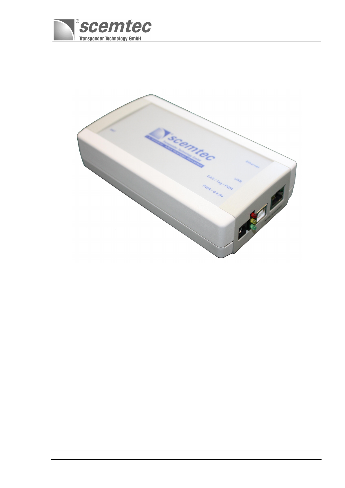
The "SIR-2010 (STK-2010) 13.56 MHz Midrange Reader System" is hereafter referred to as "Reader."
This manual describes the SIR-2010(STK-2010) 13.56 MHz Midrange Reader System, Reader for short.
This SIR-2010 Midrange Reader System is designed as a multi-tag system to read and write information
stored on transponders (tags). The operating frequency of 13.56 MHz yields a relatively wide reading
range of up to 550 mm depending on antenna system (mainly with larger externally attached antennas)
and transponder -type and -size. This first generation of SIR-20xx Midrange Readers is based on the
hardware developed by scemtec Transponder Technology featuring an RF transmitting power of
nominal 500mW @ 50Ω-load. The SIR-2010 13.56 MHz Midrange Reader System is the second
product in the SIR-20xx product family. The transmission of data between the reader and a host
computer via an USB 2.0 full speed compatible interface and an Ethernet port is available as well.
The reader is compatible with standards ISO/IEC 15693- 2 and ISO18000-3 "A."
Document No. SIR-2010 Version: 0.01 Page 4 of 15
Page 6

Power
Switching
Demod- Unit
Converter
USB
Ethernet
EEProm
Digital
Controler-
Interface
Block - Diagramm SIR - 2010 ( 13,56 MHz Midrange Reader System )
Digital
3 Block Diagram
Manual and Specification
SIR-2010 ( STK-2010 )
13.56 MHz Midrange Reader System:
Analog
FILTER
external
antenna
(via SMAconnector)
FILTER
4 Operating Modes
MIXER
PA
Power supply
6-6,5 Vol t/ DC
OSZ
13,56 MHz
Mod- Unit
Unit
A / D
Unit
18,432MHz
18,432MHz
25MHz
4.1 Self-Test (Diagnosis) and STAND-BY Operation
After the main power supply has been switched on, a green LED labeled PWR lights up, which also
supplies power to the CPU unit. The reader is ready for operation after a short self-test. The reader
carries out a short self-test each time it is switched on. This tests all key components and functions of
the reader. Once the diagnosis routines have completed successfully, the software switches to IDLE
mode, i.e. the program waits for input via one of the two described ports of the interface to switch to a
different operating mode.
At this time, the antenna does not yet transmit since the carrier is still switched off. The hardware is in
STANDBY operating mode, the carrier is not active, and the energy consumption of the reader is
minimal. The carrier is automatically switched on once the reader receives a command from the host
sent across the interface, which the reader can only carry out with activated carrier. If there is no input
for a longer period of time after executing the command, the carrier is switched off again and the
hardware enters the STANDBY mode again as well.
4.2 Reading / Writing Tags
Several tags in the field can be read or written simultaneously (anti-collision). The duration of the
reading/writing process depends on the number of tags in the field. Generally, there is no max. number
of tags that are permitted in the field at the same time.
Document No. SIR-2010 Version: 0.01 Page 5 of 15
Page 7
while operating(carrier on):@ 6 Volt / DC power supply
Manual and Specification
SIR-2010 ( STK-2010 )
4.3 EAS Antitheft
EAS is an abbreviation of Electronic Article Surveillance. This operating mode serves to monitor items or
articles electronically. The tags in the field are neither read nor written. The only thing determined is
whether a tag is in the field with a set EAS mode flag. This mode allows for greater ranges than the
read/write mode. When using an external antenna such as the scemtec SAT-A40-LR-O-13MHz with an
edge length of 400 mm (available as optional equipment), the detection range can be expanded up to
max. 600 mm.
Note: EAS mode is not supported by all silicon and transponder manufacturers.
5 Hardware
5.1 Voltage Supply
The standard version of the SIR-2010 reader in standard housing is designded for an input voltage
range of 6-6,5 Volt / =DC and a tolerance of +/- 0,5 Volt . The following input voltage ranges are thus
possible with the rated current consumptions in different operating modes:
Input voltage ranges:
= DC / direct current
Input voltage - tolerance
Current consumption of the different operating modes:
in STANDBY mode: @ 6 Volt / DC power supply
For the SIR-2010 reader system is a suitable wall plug 6 Volt =DC / 1000mA power supply also as
optional accessory available and contactable to the SIR-2010 over a 2.1mm standard barrel connector.
6-6,5 Volt
+/- 0,5 Volt
≤ 100 mA
≤ 550 mA
5.2 HF Unit
The carrier frequency of 13.56 MHz is generated in the HF unit. The final stage generates an output of
nominal 500mW @ a 50 Ω-load.
5.3 External Antenna
The reader is only operational with an external antenna. The operating frequency f0 amounts to
13.56MHz with a max. RF output of nominal 500mW @ a 50 Ω-load. Some key parameters of the
reader such as range, for example, depend on the used antenna, the used transponder type and size
and quality, and the resulting magnetic coupling between the transponder resonant circuit and the
transmission/receiver antenna.
Normally only one external antenna can be connected with a SMA plug connection located on the front
of the cable inlet side (see port labeled “ANT” output). When operating with the external antenna, this
antenna should be configured for the optimal resonance frequency of 13.56MHz with ohmic adjustment
(nominal ZF = 50 Ω) to ensure the best possible adjustment to the SIR-2010 Midrange Reader System.
Document No. SIR-2010 Version: 0.01 Page 6 of 15
Page 8

Manual and Specification
SIR-2010 ( STK-2010 )
Recommended external antennas are scemtec antenna models:
SAT-A25/30-MR-P-13MHz 250 mm * 300 mm loop antenna (acrylic glass-housing)
SAT-A40-LR-O-13MHz 400 mm * 400 mm open loop antenna
5.3.1 Antenna connector (SMA-connector location)
5.4 Digital unit
5.4.1 Processor
An “ ATMEL ARM7 “ digital processor is utilized.
5.4.2 Memory
The utilized memory consists of flash memory. The flash memory firmware can be updated at any time
using one of the two interfaces to be activated. A serial EEPROM to store the configuration data is
standard equipment.
5.5 Interfaces
5.5.1 Location of interface-connectors
5.5.2 Ethernet
The SIR-2010 Midrange Reader System is equipped with a 10/100 T-Ethernet interface.
5.5.3 USB
The SIR-2010 Midrange Reader System is equipped with a USB 2.0 full speed (12 Mbits/sec) port.
Document No. SIR-2010 Version: 0.01 Page 7 of 15
Page 9

Manual and Specification
SIR-2010 ( STK-2010 )
6 Software
6.1 Firmware for the SIR-2010 Midrange Reader System
The firmware for the SIR-2010 13.56 MHz Midrange Reader System contains all basic functions for
reading and writing of tags of different manufacturers (air protocol), numerous control functions, as well
as different diagnosis routines. These routines are used to test the key components and functions of the
reader.
A demo software for Windows is included on the CD-ROM delivered together with the device.
6.2 STX / ETX Interface Protocol
A special transfer protocol is available for the SIR-2010 13.56 MHz Midrange Reader System
documented in the scemtec STX / ETX protocol. The required STX/ETX protocol description is included
on the CD-ROM delivered together with the device.
6.3 List of supported STX/ETX Commands
6.3.1 Common:
1000: Reset Request
1001: Request Version Number
1002: Interface Test
1003: Change Baud Rate
1010: Request System Setting
1011: Edit System Setting
1019: Get Device Serial Number
1028: Get Processor Identification String
1029: Get Hardware Feature
102A: Request Interface Board Setting
102B: Edit Interface Board Setting
102C: Forward Command
102D: Request Interface Board Version Number
102E: Get Local Device Name
102F: Set Local Device Name
6010: Set Password Buffer
E000: Recover Factory Settings
E001: Recover User Settings
E002: Freeze Current Settings
E080: Read From EEPROM User Space
E081: Write To EEPROM User Space
E082: Get EEPROM User Space Size
E083: Erase EEPROM User Space
100A: Request Supported Transponder Types
F000: Switch on/off Oscillator
F001: HF Reset
Document No. SIR-2010 Version: 0.01 Page 8 of 15
Page 10

6.3.2 Code-1:
1A30: Request Setting
1A31: Edit Setting
4A14: Unselected Read
6A10: Anticollision / Select
4A10: Selected Read
5A10: Write
6A18: Halt
6A1A: Reset QUIET Bit
6A1C: EAS
6A20: Create Inventory
6A21: Get Inventory
6A22: Get ID Range from Inventory
6A23: Realtime Inventory
6A24: Create/Get Inventory
6A26: Select Individual
4A28: Looped Read
5A24: Direct Write
6A28: Direct Halt
6A29: EAS Alarm
6A2A: Request Write Protect State
6A2B: Set Write Protect
6A2C: Change EAS Bit
6A2D: Set QUIET Bit
6.3.3 ISO15693:
1C30: Request Setting
1C31: Edit Setting
1C34: Get ISO Tag Descriptor
1C35: Set ISO Tag Descriptor
1C36: Get ISO Tag Descriptor from ROM
1C38: Set Temporary Response Delay
6C10: Single Anticollision Round
6C12: Select
4C10: Read Single Block
4C12: Read Multiple Blocks
4C16: Get System Information
4C18: Get Security Status
5C10: Write Single Block
5C12: Write Multiple Blocks
5C16: Write AFI
5C17: Write DSFID
6C14: Lock Block
6C16: Lock AFI
6C17: Lock DSFID
6C18: Stay Quiet
6C1A: Reset To Ready
6C1E: Custom Read Command
6C1F: Custom Write Command
6C20: Create Inventory
6C21: Get Inventory
6C22: Get ID Range from Inventory
6C23: Realtime Inventory
6C24: Create/Get Inventory
Manual and Specification
SIR-2010 ( STK-2010 )
Document No. SIR-2010 Version: 0.01 Page 9 of 15
Page 11

4C20: Advanced Read Single Block
5C20: Advanced Write Single Block
6C26: Advanced Lock Single Block
4C24: Advanced Read Multiple Blocks
5C24: Advanced Write Multiple Blocks
6C28: Advanced Lock Multiple Blocks
5C26: Advanced Write AFI
5C27: Advanced Write DSFID
6C2A: Advanced Lock AFI
6C2B: Advanced Lock DSFID
4C2A: Looped Address Scan
6.3.4 ISO15693 / ICode-SLI(S):
6CA0: Inventory Read
6CA4: Create IR Inventory
6CA5: Get IR Inventory
6CA6: Get Single ID from IR Inventory
6CA7: Create/Get IR Inventory
6CA8: Change EAS Flag
6CA9: Lock EAS Flag
6CAA: EAS
6CAB: EAS Alarm
6.3.5 ISO15693 / ICode-SLIS:
6CAC: Password Protect EAS
6CAD: Write EAS ID
6CAE: Read EPC
6CE0: Inventory Page Read
6CE2: Get Random Number
6CE3: Set Password
6CE4: Write Password
6CE5: Lock Password
6CE6: Protect Page
6CE7: Lock Page Protection
6CE8: Get Protection Status
6CE9: Destroy
6CEA: Enable Privacy
6CEB: 64 Bit Password Protection
6CAF: Login
6CEC: Create IPR Inventory
6CED: Get IPR Inventory
6CEE: Get Single ID from IPR Inventory
6CEF: Create/Get IPR Inventory
6.3.6 ISO15693 / Tag-it HF-I:
5C82: Write Two Blocks
Manual and Specification
SIR-2010 ( STK-2010 )
Document No. SIR-2010 Version: 0.01 Page 10 of 15
Page 12

6.3.7 ISO15693 / My-D:
4C90: Read Block
5C90: Write Block
6C94: Lock Block
6.3.8 ISO15693 / EM4034:
6CC0: Login
6.3.9 ISO15693 / VarioSens:
6CD0: Init
6CD1: Set Log Mode
6CD2: Set Log Timer
6CD3: Set Custom
6CD4: Start Log
6CD5: Get Log State
6CD6: Set Passive
6CD7: Get Timer State
6CD8: Get State
6CD9: Get One Block
6CDA: Timer Sync
6CDB: Get Voltage
6CDC: Set Calibration
6CDD: Verify Password
6CDE: Set Password
6CDF: Verify Buffered Password (Schreiner e-Temp)
6CBA: Easy Init
6CBB: Get Config
6CBC: Get Progress
6CBE: Read Single Measurement
6CBF: Get Battery Voltage
6.3.10 ISO15693 / ScemTag Sensor Tag:
6CF0: Single Measurement
6CF1: Set Configuration
6CF2: Set Threshold Values
6CF3: Start Log
6CF4: Stop Log
6CF5: Get Log Status
6CF6: Get Configuration
6CF7: Get Threshold Values
6CF8: Read Log Value
6CF9: Get Version Information
6CFA: Read Sensor Configuration
6CFB: Write Sensor Configuration
4CF0: Read EEPROM
5CF0: Write EEPROM
Manual and Specification
SIR-2010 ( STK-2010 )
Document No. SIR-2010 Version: 0.01 Page 11 of 15
Page 13
Manual and Specification
SIR-2010 ( STK-2010 )
7 Diagnosis
7.1 Self-Test (POST)
A selftest POST (Power On Self Test) is carried out automatically after turning on or connecting to the
mains power supply. This also includes testing the key components and functions of the reader. Should
a malfunction occur while using the SIR-2010 Midrange Reader System, simply load the POST
diagnosis by turning the unit (or the mains power supply) off and then on again. The displayed error
message then helps in solving the problem quickly and reliably. Numerous software commands for a
targeted diagnosis are available as well.
7.2 LEDs
7.2.1 External Diagnosis LEDs
Three external LEDs provide users with a diagnosis of the most important monitoring functions "Power" ,
"Tag Detect" and “EAS”
Three external LEDs to indicate important operating states
LED Color Designation Description
1 GREEN PWR The voltage supply for the CPU is ensured
2 YELLOW Tag A read or write process for the transponders in the magn.
field has concluded successfully
3 RED EAS
EAS is an abbreviation of Electronic Article Surveillance
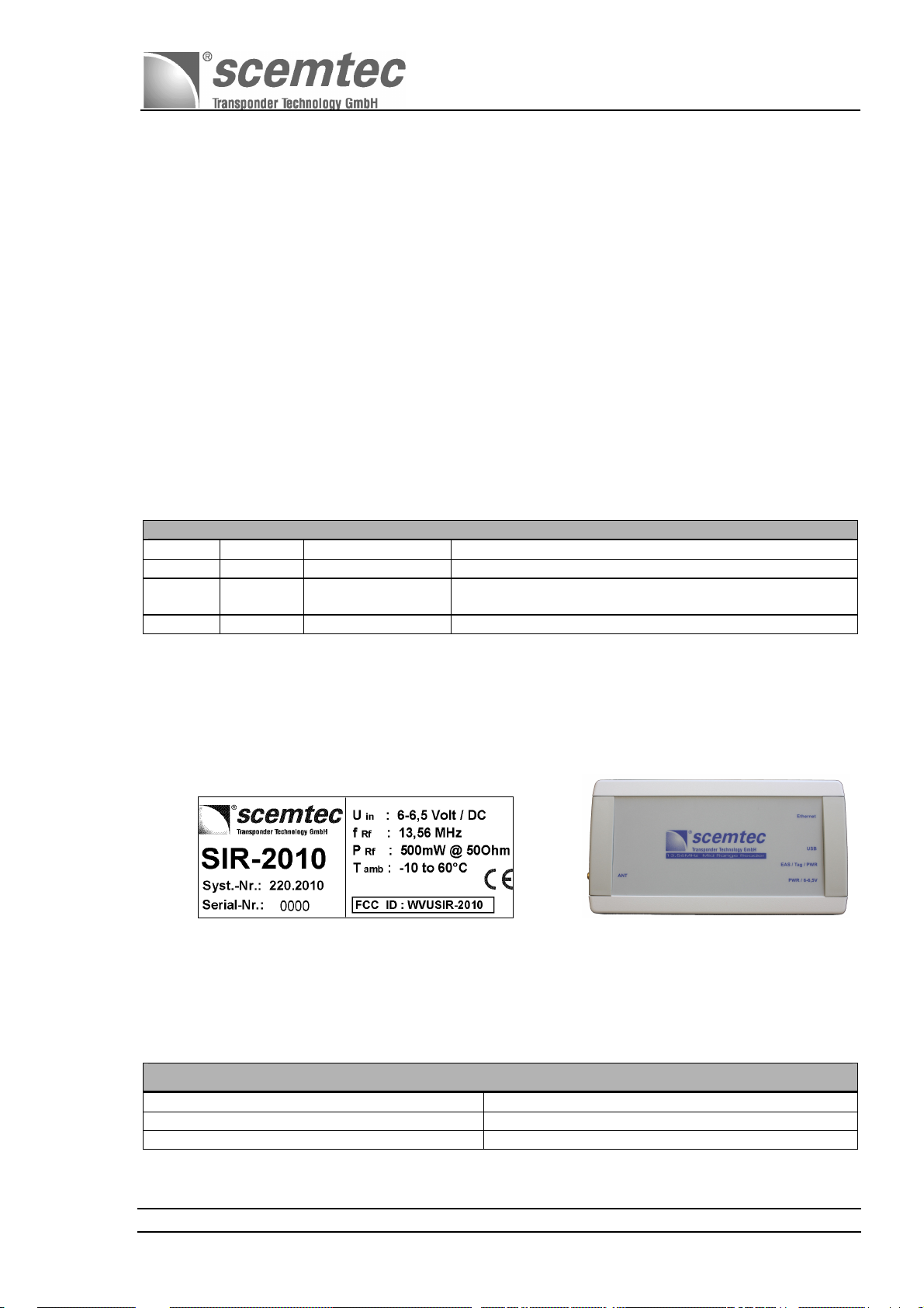
7.3 Label / Type Plate
The SIR-2010 MHz Midrange Reader System features a system label that provides information about
the specific scemtec system number "220.2010" and the consecutive serial number (four digits), e.g.
"0001" of the production lot.
System-Label on buttom of the housing Type-Plate on top of the housing
8 Mechanical Data / Housing
A plastic housing protection type IP 20 (in acc. with DIN EN 60529) is used.
Case dimensions (exterior)
Length 160 mm
Width 85 mm
Height 40 mm
Document No. SIR-2010 Version: 0.01 Page 12 of 15
Page 14
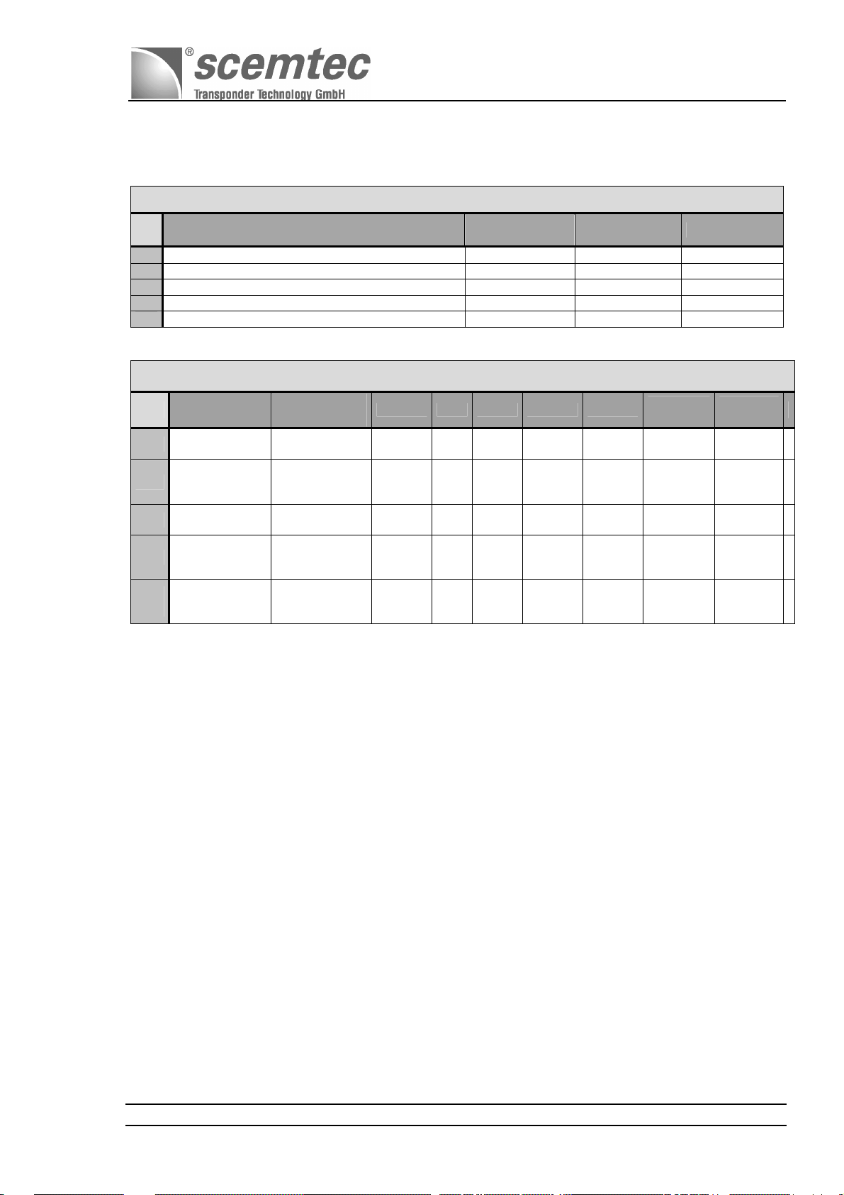
9 Electrical Data
No.
:
1
2
3
4
5
Max. current consumption / @ 6Volt DCin
Operating (ambient) temperature range
Storage temperature range
Parameter
Min. DC input voltage
Max. DC input voltage
Absolute Max. Parameters
General Parameters
Symbol
V
min
V
max
I
max
T
amb
T
stg
Manual and Specification
SIR-2010 ( STK-2010 )
Value
6,0 Volt
7,5 Volt
600 mA
- 10 to 60
- 20 to 70
Unit
°C
°C
No. Parameter
6
7
8
9
11
Operating
frequency
RF output-
power 50Ω
RF input
sensitivity
Current
consumption at
U
in
Current
consumption at
U
in
= 6 Volt
= 6 Volt
condition
Defined in
ISO document
resistance 50Ω
P
out
T
RF
T
Idle - mode
T
Test
Terminal
/25°C
=500mW
amb = 25°C
=500mW
out
amb = 25°C
amb = 25°C
Symbol Min. Typ.
F
RF
P
out
- tbd
I
in
I
in
Max.
Unit
- 13.56 - MHz
- 1db 500 + 1db
470 520 570 mA
80 100 120 mA
mW
- dBm
Min / Max
values
X
X
X
X
Typ.
values
X
X
X
10 Conformity
10.1 CE Conformity
The company scemtec Transponder Technology GmbH declares that the product device type
13.56MHz Mid Range Reader with the type designation
SIR-2010
complies with the basic requirements of Directive
1999/5/EC
of the European Council.
The following standards were used as the basis for this evaluation:
EN 300 330 (Part Radiated Spurious Emission)
EN 301 489-1, -3
EN 60950
Document No. SIR-2010 Version: 0.01 Page 13 of 15
Page 15

10.2 FCC Conformity: Information for USA
This device complies with Part 15 of the FCC Rules. Operation is subject to the
following two conditions:
(1) This device may not cause harmful interference, and
(2) this device must accept any interference received, including
Interference that may cause undesired operation.
Usually this is followed by the following FCC caution:
Any changes or modifications not expressly approved by the party
responsible for compliance could void the user's authority to operate this
equipment.
Note: This equipment has been tested and found to comply with the
limits for a Class A digital device, pursuant to part 15 of the FCC
Rules. These limits are designed to provide reasonable protection
against harmful interference when the equipment is operated in a
commercial environment. This equipment generates, uses, and can radiate
radio frequency energy and, if not installed and used in accordance with
the instruction manual, may cause harmful interference to radio
communications. Operation of this equipment in a residential area is
likely to cause harmful interference in which case the user will be
required to correct the interference at his own expense.
Manual and Specification
SIR-2010 ( STK-2010 )
Professional Installation: To comply with FCC part 15 rules in the United States, the system must be professionally installed to
ensure compliance with the Part 15 certification.
It is the responsibility of the operator and professional installer to ensure that only certified systems are deployed in the United
States. The use of the system in any other combination (such as co-located antennas transmitting the same information) is
expressly forbidden.
11 Delivery Scope / Optional Equipment and Accessories
11.1 Manual, CD-ROM, Test Software, Protocol Description
11.2 Optional Accessories / External Antenna(s)
For the SIR-2010 reader system is a suitable wall plug 6 Volt =DC / max.1000mA power supply as
optional accessory available and contactable to the SIR-2010 over a 2.1mm standard barrel connector.
Two standard antenna models are sold by scemtec:
SAT-A25/30-MR-P-13MHz
SAT-A40-LR-O-13MHz
12 Datasheet
See additional document : datasheet “ SIR-2010 “
Document No. SIR-2010 Version: 0.01 Page 14 of 15
Page 16

Manual and Specification
SIR-2010 ( STK-2010 )
13 Related Documents / Document History
STX/ETX Protocol description : scemtec's STX/ETX Protocol description is distributed with every
Reader on the product CD
13.1 Document History
Version Date Changed by Description
0.01 11.04.2011 Radermacher Initial Version
Document No. SIR-2010 Version: 0.01 Page 15 of 15
 Loading...