

Page 1

Date: 2014-03-07
Page 1 of 1
Vers. no. 1.14
m. dudde hochfrequenz-technik
Rottland 5a
D-51429 Bergisch Gladbach/ Germany
Tel: +49 2207-96890
Fax +49 2207-968920
Annex no. 5
Functional Description /
User Manual
Page 2
Manual
SIL-2125 v0.8
project name version
SIL-2125 0.8
build date author last change author
05.01.2011 B. Bröhl 10.12.2014 B. Bröhl
last print: no. of pages
07/24/2014 23
Path:
P:\SHL-2xxx_SIL-2xxx\SIL-2125\Spezifikation\Manual-SIL2125_v0.8.odt
project manager development manager Managing director customer
<project manager> Burkhard Bröhl Jürgen Kalbitzer <customer>
Page 3

Manual SIL-2125 v0.8
Contents
1 Safety Informations..........................................................................................................................3
2 General ............................................................................................................................................4
3 RFID Systems...................................................................................................................................5
4 System Description...........................................................................................................................6
5 Quick Start........................................................................................................................................7
6 Hardware..........................................................................................................................................8
6.1 Voltage Supply ........................................................................................................................8
6.2 Interfaces...................................................................................................................................8
6.2.1 Ethernet.............................................................................................................................8
6.2.2 USB...................................................................................................................................9
6.2.3 RS 232 Interface................................................................................................................9
6.3 HF Unit.....................................................................................................................................9
6.4 External Antenna....................................................................................................................10
6.5 Reader Versions......................................................................................................................10
6.5.1 Internal Splitter (standard)..............................................................................................10
6.5.2 Internal Multiplexer .......................................................................................................10
6.6 Inputs and Outputs..................................................................................................................11
6.6.1 Binary Inputs...................................................................................................................11
6.6.2 Binary Outputs................................................................................................................11
6.6.3 IO connection example...................................................................................................11
6.7 Diagnosis LEDs......................................................................................................................13
6.8 Processors...............................................................................................................................13
6.9 Memory...................................................................................................................................13
7 Operating Modes............................................................................................................................14
7.1 Standard (Host) Mode.............................................................................................................14
7.2 Stand alone Mode (SMART Read).........................................................................................14
8 Software..........................................................................................................................................15
8.1 Software utilities.....................................................................................................................15
8.2 Firmware ................................................................................................................................15
8.3 STX-ETX Interface Protocol .................................................................................................15
9 Electrical specification...................................................................................................................16
10 Mechanical Specification & Mounting........................................................................................18
10.1 Dimensions...........................................................................................................................18
10.2 Mounting...............................................................................................................................18
11 FCC Conformity: Information for USA.......................................................................................19
12 Delivery Scope / Optional Equipment and Accessories...............................................................20
12.1 Delivery Scope .....................................................................................................................20
12.2 Optional Accessories............................................................................................................20
13 Related Documents.......................................................................................................................21
14 Contact STT..................................................................................................................................22
15 Document History........................................................................................................................23
Page 2 of 23
Page 4

Manual SIL-2125 v0.8
1 Safety Informations
As with all electronic systems, the system described hereafter may not be used for any
applications critical for maintaining safety. This means, the products may not used in life support applications or any other life critical applications that could involve potential risk of
death, personal injury or severe property or environmental damage.
The user/operator is solely responsible for any damages resulting from an improper or unintended utilization of the system.
Page 3 of 23
Page 5

Manual SIL-2125 v0.8
2 General
Scemtec Transponder Technology GmbH (STT) reserves the right to make changes or to discontinue its products or services at any time without notice.
STT takes no responsibility for customer applications, products, or performance relating to systems
or applications incorporating with STT products.
STT assumes no liability and is not responsible for infringement of patents and/or any other intellectual or industrial property rights of third parties, which may result from assistance provided by
STT.
Please note, that the user is responsible for conformity with regulation issues (e.g. radio approval),
when using antennas not provided by STT or using the system in countries, where the conformity
with local regulations is not tested by STT.
All other products mentioned in this document might be brands or brand names of the different suppliers.
Copyright © 2014 scemtec Transponder Technology GmbH (STT)
Page 4 of 23
Page 6

Manual SIL-2125 v0.8
3 RFID Systems
As this technology is based on radio frequency, one must exercise the following operational and
mounting instructions to achieve best performance:
• Metal affects radio signals. Normally the antenna has to be as far away as possible from any
metal object and it’s damping influence on the magnetic field. Only this leads to the best
distribution of the magnetic field in the reading range. Very important as well is not to have
“short circuits”, in the vicinity of the antenna, damping the magnetic field. A “short circuit”
is any metal near the antenna, building a “metallic ring”, so that currents introduced by the
RF-field can flow, absorbing the energy needed for the tag to operate.
• Care must be taken to reduce or eliminate unwanted signals (so called interference or noise)
from external sources. The reading range may be reduced by following noise sources:
• portable two way radio
• cellular phones
• switching power supplies
• computer monitors
• frequency converters (e.g. motor control systems)
• The read range is depending upon
• performance of the Reader
• size of the antenna
• size of the tag (the bigger the better)
• orientation of the tag antenna plane to the Reader antenna plane
• quality of the tag
• matching of Reader antenna size and tag (-antenna) size
• environmental, electrical noise
• If influence of metal can not be fully avoided a tuning of the antenna is required and
will improve reading range
Page 5 of 23
Page 7

Manual SIL-2125 v0.8
4 System Description
This manual describes the 13,56 MHz Long Rang Reader System „SIL-2125“, hereafter referred to
as "Reader".
The 13,56 MHz Long Range Reader system „SIL-2125“ is designed as a multi-tag system for reading and writing information stored on transponders (TAGs). It is primarily designed to be operated
with so called Gate-antennas. Therefore a splitter is integrated in the standard version, which divides the output-power generated by output stage symmetrically to two BNC antenna connectors.
Nevertheless the standard version can be configured to operate with only one antenna attached to
Antenna Port ANT1 with slightly reduced output power.
Beside this a MUX Version with integrated antenna multiplexer is available. This version offers 4/8
antenna ports with SMA connectors for attaching external antennas.
The Reader is designed for indoor usage only.
Transfer of data between the Reader and a host computer is possible via Ethernet, USB and an
asynchronous RS232 interface. Furthermore a configurable “stand-alone” operation via so called
Smart Read Feature is possible.
The Reader is compatible with the ISO/IEC 15693-2 and ISO 18000/3 “A” and “C” standards.
Page 6 of 23
Page 8
Manual SIL-2125 v0.8
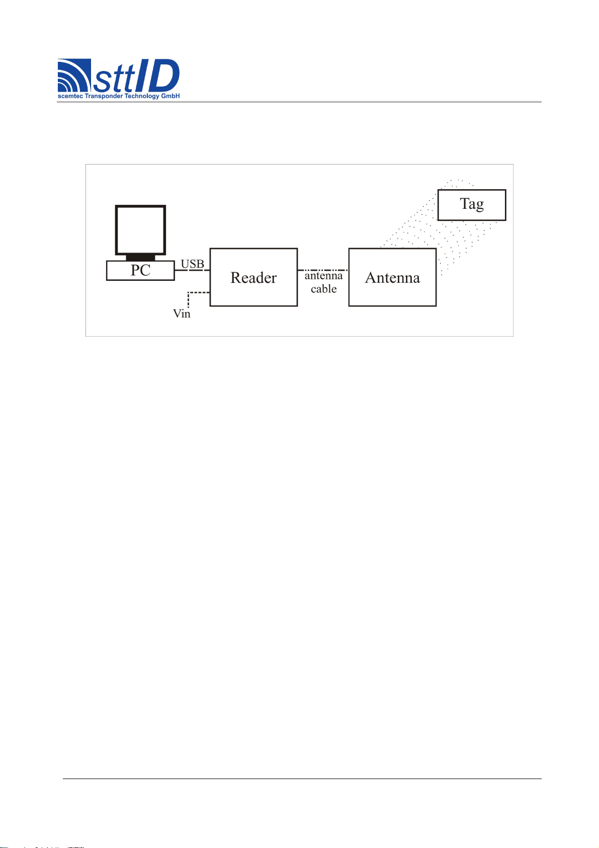
5 Quick Start
First Connect the Reader as shown below:
As example you can use the STT antenna “SAT-A40-LR-O-13MHz” [400.4020].
Now you can use a Software like “Uni - Demo” to control the Reader. For more details please refer
to “Quick Start Guide read”. This Guide is available for download on www.stt-rfid.com.
Page 7 of 23
figure 1: Reader connection example
Page 9

Manual SIL-2125 v0.8
6 Hardware
6.1 Voltage Supply
The Reader is designed for a voltage supply connectible via an standard 2.1-mm barrel connector.
Polarity of connector
The reader may only be connected to a power supply with a maximum output current of 2 A, which
is tested for safety according to appropriate standard (e.g. EN60950)
A suitable wall plug power supply is available as optional accessory. For best performance and
safety, STT strongly recommends to use only this power supply
6.2 Interfaces
For communication with a host device (e.g. PC), the Reader provides three interfaces (RS232, USB,
Ethernet). The interfaces are handled by an separate, built-in interface unit with an ARM7 microprocessor. This interface-unit can also be configured to operate the Reader in stand-alone mode
(Smart Read feature).
The interfaces are intended to be used only with connection cables not longer than 3m.
6.2.1 Ethernet
The Reader is equipped with a 10/100 T-Ethernet interface.
By default the Reader gets his IP Address via DHCP. Nevertheless the Reader can also be configured with a static IP Address. Configuration can be done via a simple integrated web server,
which can be reached by typing the actual IP Address in the address line of browser. After Login,
configuration page for of Network settings is available.
Default Login Settings:
Username: admin
Password: scemtec
The actual assigned IP address of the reader can be determined using STT Demo Software (e.g.
Unidemo). Clicking the “Search” Button in Ethernet connection window of the STX/ETX connector will show the actual IP address as well as MAC address of all STT devices available in the local
network.
Network settings may also be configured by using STX-ETX commands. For details please refer to
STX-ETX protocol description.
Page 8 of 23
Page 10

Manual SIL-2125 v0.8
6.2.2 USB
The Reader is equipped with a USB 2.0 full speed (12 Mbits/sec) port. The connection is made via
a standard USB-B connector.
Supported profiles CDC-ACM (virtual COM-Port), HID (Keyboard emulation)
Appropriate drivers for Windows are available for download on www.stt-rfid.com.
6.2.3 RS 232 Interface
The Reader is equipped with a RS232 interface. The connection is made via a standard 9 pin D-Sub
connector .
Terminal designation: SUB-D Connector Pin Terminal Function
TxD 2 Transmit Data
RxD 3 Receive Data
GND 5 Ground
The data transfer rate is adjustable via STX-ETX commands.
Configuration 8 Data Bits, 1 Stop Bit, no Parity, no flow control
Supported Data Rates [baud]
1200, 2400, 4800, 9600 (default), 19200, 38400 57600, 115200,
230400
In addition to the primary RS232 Interface described above, the Reader provides a secondary RS
232 Interface, intended to be used in stand alone mode as interface for connecting auxillary
equipment (e.g. additional RFID reader, bar code scanner, …). The connection to the secondary
RS232 ist also made via the 9 pin SUB D connector. Please contact STT for further Information
regarding usage of the second RS232 in your application.
Terminal designation: SUB-D Connector Pin Terminal Function
TxD2 8 Transmit Data Secondary RS232
RxD2 7 Receive Data Secondary RS232
GND 5 Ground
Special Adapters cables for connecting external devices to the secondary RS232 are available from
STT.
6.3 HF Unit
The carrier frequency of 13.56 MHz is generated in the HF unit. The final stage generates an output
of typical 10 watt on nominal ZF = 50 Ohm.
Page 9 of 23
Page 11

Manual SIL-2125 v0.8
6.4 External Antenna
The Reader is only operational with external antenna(s).
Some key parameters of the Reader such as reading range for example depends on the used antenna,
the used transponder type,size and quality, and the resulting magnetic coupling between the transponder resonant circuit and the transmission/receiver antenna.
The connected antenna(s) should be configured for the optimal resonance frequency of 13.56MHz
with ohmic adjustment (nominal ZF = 50 Ohm) to ensure the best possible system performance.
When using antennas not provided by STT, please make sure that the antenna quality factor is in the
range between 20 and 50 and the antenna is optimally tuned. The resulting SWR value should be
well below 2.
Antenna tuning should be checked at the final installation. Furthermore antenna detuning caused by
heating of the antenna matching unit should also be observed
6.5 Reader Versions
The Reader is available in two versions. The standard version is equipped with a Splitter, which divides the output power to two antenna ports for operating two antennas simultaneously.
Beside this a version with integrated antenna Multiplexer (MUX) is available, which switches the
output power to one of up to 4 or 8 antenna ports, for sequential operating of attached antennas.
6.5.1 Internal Splitter (standard)
For using the standard version of the Reader with two antennas (e.g. a Gate antenna) the Split-mode
is available. In this mode the built in splitter divides this power symmetrically to the two antenna
connectors. So typical 5 watt on nominal ZF = 50 Ohm is available at each of the two antenna BNC
connectors. For using the Reader with a single antenna setup, a Single-mode is available. In this
mode a slightly reduced HF power of typ. 7,5 Watt on nominal ZF = 50 Ohm is only available on
antenna port ANT 1.
The desired operation mode can be selected via a software command. Furthermore the output power
can be reduced by software commands in both operation modes.
6.5.2 Internal Multiplexer
In this version up to 4/8 antennas (Depending on the stage of expansion of the integrated MUX) can
be connected to the Reader. The user can select each connected antennas with software commands.
In this version a slightly reduced HF power of typ. 7,5 Watt on nominal ZF = 50 Ohm is available
on the selected antenna port at any one time.
Furthermore the output power can be reduced by software command.
The MUX Version is equipped with SMA antenna connectors. For using with BNC or N connectors, SMA-BNC or SMA-N Adapters are available from STT.
Page 10 of 23
Page 12

Manual SIL-2125 v0.8
6.6 Inputs and Outputs
6.6.1 Binary Inputs
Two binary inputs are available for customer-specific tasks. Both inputs are accessible with indirect-connected opto-couplers and screw terminals (see terminal description below).
The state of both binary inputs must be imported unambiguously via software command.
In stand alone mode (SMART Read) the behavior of the Inputs can be configured freely (e.g. trigger Read event).
Input designation: Terminal designation: Internal opto-coupler assignment:
Input 1
I1 + (A) Anode of the opto-coupler input 1
I1 – (K) Cathode of the opto-coupler input 1
Input 2
I2 + (A) Anode of the opto-coupler input 2
I2 – (K) Cathode of the opto-coupler input 2
All screw terminals are clearly marked with their specific designation at the terminal. The screw terminals accepts wires of maximum conductor cross-section of 2.5mm².
The electrical data can be found in the table 'electrical specification'.
6.6.2 Binary Outputs
Two binary outputs in the form of potential-free contacts are available for customer-specific tasks.
Both outputs are accessible with indirect-connected relays and screw terminals (see terminal description below). They are freely configurable via software commands.
In stand alone mode (SMART Read) the behavior of the Outputs can be configured freely (e.g.
change state when TAG is read).
Terminal assignment:
Input designation: Terminal designation: Internal assignment:
Output 1
(normally open)
O1.1 Contact 1 of the potential-free Output-port 1
O1.2 Contact 2 of the potential-free Output-port 1
Output 2
(normally open)
O2.1 Contact 1 of the potential-free Output-port 2
O2.2 Contact 2 of the potential-free Output-port 2
All screw terminals are clearly marked with their specific designation at the terminal. The screw
terminals accepts wires of maximum conductor cross-section of 2.5mm².
The electrical data can be found in the table 'electrical specification'.
6.6.3 IO connection example
The following schematic is an example how to connect the Inputs and Outputs.
Page 11 of 23
Page 13

Manual SIL-2125 v0.8
Page 12 of 23
figure 2: IO connection example
Page 14

Manual SIL-2125 v0.8
6.7 Diagnosis LEDs
Three external LEDs provide users with a diagnosis of the most important monitoring functions
"Power", "Tag Detect" and “EAS”.
Three LED indicate important operating states
Led Color Designation Description
1 green Power The voltage supply for the CPU is ensured
2 yellow Tag Detect A read or write process for the transponders has concluded successfully
3 red EAS EAS*Alarm is deployed
*EAS is an abbreviation of Electronic Article Surveillance
6.8 Processors
The Reader incorporates two Microprocessor. One handles the interface communications with the
connected host systems as well as stand alone operations (interface processor).
The second processor (main processor) handles all actions related to Communication with
Transponders
6.9 Memory
The firmware of the incorporated microprocessors is stored in a flash memory. It can be updated at
any time via the USB or RS232 interface.
A serial EEPROM to store configuration and user data is also available.
Page 13 of 23
Page 15

Manual SIL-2125 v0.8
7 Operating Modes
7.1 Standard (Host) Mode
In standard mode the Reader is completely controlled by a Host system connected to one of the
available Interfaces via STX-ETX commands. For further information, please refer to the STXETX protocol description, which can be downloaded from www.stt-rfid.com.
7.2 Stand alone Mode (SMART Read)
In addition to controlling the Reader with a host system via one of the interfaces, it can also be configured for stand alone operation. Therefore the “Smart Read” feature is implemented.
For further Information about Smart Read please refer to the correspondent Smart Read manual,
which can be downloaded from www.stt-rfid.com.
Page 14 of 23
Page 16

Manual SIL-2125 v0.8
8 Software
8.1 Software utilities
Various software utilities for Windows for the Reader are available for download on www.stt-rfid.com. Linux Versions are available on request.
Available Software utilities:
• UniDemo: Universal Demo Software for easily controlling the Reader with a
Host system.
• STXTerm: Terminal program for controlling the Reader with a Host system by
directly submitting STX-ETX commands. For submitting multiple
STX-ETX commands a comprehensive Script utility is implemented
• Flasher: Utility for updating firmware on the incorporated Microprocessors
• SmartManager: Utility for configuration and using the Reader in Standalone mode
(Smart Read).
8.2 Firmware
The firmware of the Reader contains all basic functions for reading and writing tags of different
manufacturers (air protocol), numerous control and configuration functions, as well as different diagnosis routines.
Firmware can be updated by the user via USB or RS232 Interface. Therefore the latest Firmware
files are available for download on www.stt-rfid.com.
8.3 STX-ETX Interface Protocol
For communication with the Reader STT STX-ETX protocol is used.
The required STX/ETX protocol description can be downloaded from www.stt-rfid.com
A list of supported STX-ETX commands can be read out from the Reader via the STX-ETX command ‘100E’ or via STX-ETX script ‘Get Fn List.stx’ (which will be installed together STXTerm
software ).
Page 15 of 23
Page 17

Manual SIL-2125 v0.8
9 Electrical specification
Electrical specification
(Ambient temperature: 25°C)
Parameter Test condition Symbol Min. Typ. Max. Unit
DC input voltage -
V
IN
23 24 25 Volt
Current consumption
Carry on (2x5W)
V
IN
= 24V
I
IN
- - 2000 mA
Current consumption
Idle - mode
V
IN
= 24V
I
IN
- - 500 mA
Operating frequency -
F
RF
- 13,56 - MHz
RF power (internal) -
P
internal
- 1db 10 + 1db W
Input voltage binary inputs
I1/ I2
-
V
input
18 24 30
Volt
DC
Input current binary inputs
I1/ I2
V
input
= 24V/DC I
input
- 22 - mA
Series resistors binary in-
puts I1/ I2
-
R
IN
950 1000 1050 Ohm
Output switching voltage
binary outputs O 1 / O 2
-
V
output
(AC/DC)
- - 30
Volt
AC/DC
Output switching current
binary outputs O1 / O 2
V
output
=12 V/DC I
out
- - 1 A
Output power dissipation
binary outputs O 1 / O 2
V
output
=12 V/DC P
out
- - 500 mW
On resistance binary out-
puts O 1 / O 2
- R
on
- 0,25 0,50 Ohm
Operating (ambient) tem-
perature range
-
T
amb
0 - 40 °C
Storage temperature range
-
T
stg
-20 - 70 °C
Page 16 of 23
Page 18

Manual SIL-2125 v0.8
Page 17 of 23
figure 3: Block diagram
Page 19

Manual SIL-2125 v0.8
10 Mechanical Specification & Mounting
10.1 Dimensions
An aluminum housing protection type IP 20 (in acc. with DIN EN 60529) is used. This housing is
equipped with two lateral covers attached with screws. For mounting the Reader the two included
mounting brackets can be attached.
Housing dimensions
Length 210 mm
Width 220 mm (without brackets)
High 68 mm
Color Natural matte aluminum
10.2 Mounting
When mounting the Reader on a wall or ceiling, only the provided screw-holes has to be used. Fixing to the wall/ceiling has to be done with appropriate installation material (not included) using all
of the foreseen mounting points.
When installing the Reader, please make sure that the maximum ambient temperature is not exceeded at any time. Therefore the Reader should only be installed in places where sufficient ventilation is assured. Any kind of possible heat accumulation should be avoided (e.g. the SIL should not
be mounted in an additional housing or cabinet).
Page 18 of 23
Page 20

Manual SIL-2125 v0.8
11 FCC Conformity: Information for USA
This device complies with Part 15 of the FCC Rules. Operation is subject to the
following two conditions:
(1) This device may not cause harmful interference, and
(2) this device must accept any interference received, including
Interference that may cause undesired operation.
Usually this is followed by the following FCC caution:
Any changes or modifications not expressly approved by the party
responsible for compliance could void the user's authority to operate this
equipment.
Note: This equipment has been tested and found to comply with the
limits for a Class A digital device, pursuant to part 15 of the FCC
Rules. These limits are designed to provide reasonable protection
against harmful interference when the equipment is operated in a
commercial environment. This equipment generates, uses, and can radiate
radio frequency energy and, if not installed and used in accordance with
the instruction manual, may cause harmful interference to radio
communications. Operation of this equipment in a residential area is
likely to cause harmful interference in which case the user will be
required to correct the interference at his own expense.
Professional Installation: To comply with FCC part 15 rules in the United States, the system must
be professionally installed to ensure compliance with the Part 15 certification.
It is the responsibility of the operator and professional installer to ensure that only certified systems
are deployed in the United States. The use of the system in any other combination (such as colocated antennas transmitting the same information) is expressly forbidden.
Page 19 of 23
Page 21

Manual SIL-2125 v0.8
12 Delivery Scope / Optional Equipment and Accessories
12.1 Delivery Scope
• SIL-2125 Reader system
• 2 mounting brackets
12.2 Optional Accessories
For the SIL-2125 Reader system a suitable wall plug 24 volt =DC / max. 2000mA power supply as
optional accessory is available and contactable to the SIL-2125 over a 2.1-mm standard barrel
connector.
For connecting STT standard long range antennas (normally equipped with BNC Connectors) to the
MUX version of the Reader, suitable SMA-BNC adapter cables are available.
Page 20 of 23
Page 22

Manual SIL-2125 v0.8
13 Related Documents
• QuickStart Guide read
◦ Short introduction for using the Reader with UniDemo
• Quick guide to STXETX-protocol
◦ Short introduction of basic structure of STX-ETX protocol
• STX/ETX Protocol description
◦ Detailed Description of command structure and available commands for controlling the
Reader with a Host system
• SmartRead Manual
◦ Description of functionality for stand alone operation
• SmartManager Manual
◦ Description for using the SmartManager to configure a Reader for stand alone operation
• C# Demo with source code
◦ Example code for integrating the Reader in your own application software
All documents are available for download on www.stt-rfid.com.
Page 21 of 23
Page 23

Manual SIL-2125 v0.8
14 Contact STT
Scemtec Transponder Technology GmbH
Wehrstr. 1
D-51645 Gummersbach
Phone: + 49 (0) 22 61 / 80407 - 0
Fax: + 49 (0) 22 61 / 80407 - 55
e-Mail: info@stt-rfid.com
Website: www.stt-rfid.com
If you have any questions about our products, please do not hesitate to call us. Our specialists are
always available for you and will provide professional support to find a solution to your specific
problem.
Page 22 of 23
Page 24

Manual SIL-2125 v0.8
15 Document History
Version Date Changed by Description
0.1 05.01.2011 B. Broehl Initial Version
0.2 11.11.2011 B. Broehl Completely revised version
0.3 25.11.2013 B. Broehl
General mistakes corrected
MUX version added
Interface section corrected
Entries of responsible persons on front page revised
Chapter “Related Documents” revised
0.4 13.06 2013 B. Broehl Revised and corrected version
0.5 18.09.2014 B. Broehl Completely revised version
0.6 01.10.2014 B. Broehl Secondary RS232 Description added
0.7 14.11.2014 B. Broehl
Chapter 2: Regulation issues supplemented
Chapter 6.4: Information on antenna parameters
supplemented
Chapter 10.2: Information on mounting issues
supplemented
Company logo updated
0.8 10.12.2014 B. Broehl
Chapter 11: FCC Conformity: Information for USA
supplemented
Page 23 of 23
 Loading...