


t m
iNSIGHT
20
Operator’s Guide

Operator’s Guide
iNSIGHTTM 20

Copyright © 2009
Scantron Corporation
All rights reserved.
Printed in the United States of America.
For Users in the United States
This equipment complies with the requirements in part 15 of FCC Rules for a Class A computing
device. Operation of the equipment in a residential area may cause unacceptable interference to radio
and television reception requiring the operator to take whatever steps are necessary to correct the
interference.
For Users in Canada
The digital apparatus does not exceed the Class A limit for radio noise emission from digital apparatus
set in the Radio Interference Regulations of the Canadian Department of Communications.
Le présent appareil numérique n’émit pas de bruits radioélectriques dépassant les limites applicables
aux appareils numériques de la classe A prescit dans le réglement sur le brouillage radioélectrique édicté
par le Ministre des Communications du Canada.
Trademarks
iNSIGHT, Prosper, ScanFlex, PrintFlex, Scantron DesignExpert, ScanTools, Scantron, and the logo
are trademarks in the U.S. and/or other countries, of Scantron Corporation or its affiliate(s).
NestorReader is a trademark of Nestor, Inc.
Remark Classic OMR is a registered trademark of Gravic, Inc.
Liquid Paper is a registered trademark of Sanford, a division of Newell Rubbermaid.
Tipp-Ex and Wite-Out are registered trademarks of the BIC Group and BIC USA, Inc. respectively.
PostScript is a registered trademark of Adobe Systems, Inc.
Pentium is a trademark of Intel Corporation.
Microsoft, Windows, Windows XP, .NET, and Vista are trademarks or registered trademarks of
Microsoft Corporation in the United States and other countries.

P
Preface
About This Manual
This Operator's Guide is your guide for day to day use of your scanner. It provides
the information you need to handle basic tasks related to scanner operation and
simple maintenance. For information on data collection and document imaging tasks,
consult the iNSIGHT 20 Data Collection and Document Imaging Guide.
Document Organization
This manual is organized as follows:
• Chapter 1, “iNSIGHT 20 Dual Purpose Scanner”, provides an overview of the
iNSIGHT 20 scanner’s features as well as safety and environmental information.
• Chapter 2, “Scanner Basics”, describes the basics of using your scanner.
• Chapter 3, “Installation”, describes how to install your scanner.
• Chapter 4, “Maintenance”, describes routine cleaning as well as how to replace
parts that may wear out with use.
• Chapter 5, “Troubleshooting”, describes how to go about correcting issues preventing your scanner from operating properly.
Operator’s Guide iii

Preface
• Chapter 4, “Product Support and Services”, describes how to get help on the
Web, how to contact Scantron customer support, as well as how to order supplies
and forms.
Related Documentation
This manual is part of a documentation set for the iNSIGHT 20 scanner. The
documentation set provides information on packaging, installation, setup, operation,
and configuration for users and system administrators. The documentation set
consists of the following:
• What’s in This Box for the iNSIGHT 20 Scanner (Publication Number 277 160 xxx*)
• Quick Start for the iNSIGHT 20 Scanner (Publication Number 277 158 xxx*)
• Quick Tips for the iNSIGHT 20 Scanner (Publication Number 277 159 xxx*)
• Scantron iNSIGHT 20 Scanner Operator’s Guide (this manual, Publication Number
277 157 xxx*)
• Scantron iNSIGHT 20 and iNSIGHT 30 Scanner Data Collection and Document Imaging
Guide (Publication Number 277 156 xxx*)
• ScanTools® Plus User’s Guide** (Publication Number 203 821 xxx*)
• ScanTools Plus Help System** (This documentation is included with the ScanTools software and contains comprehensive information to help you with software
and hardware issues.)
* Where xxx indicates the current revision number.
** This documentation is included only if your scanner came bundled with ScanTools
Plus data collection software.
iv Scantron iNSIGHT 20 Scanner

Table of Contents
Preface iii
Chapter 1:
iNSIGHT 20 Dual Purpose Scanner 1
Scanner Hardware Features . . . . . . . . . . . . . . . . . . . . . . . . . . . . . . . . . . . . . . . . . 3
T
Data Collection Features . . . . . . . . . . . . . . . . . . . . . . . . . . . . . . . . . . . . . . . . . . . 4
Document Imaging Features. . . . . . . . . . . . . . . . . . . . . . . . . . . . . . . . . . . . . . . . . 5
System Requirements . . . . . . . . . . . . . . . . . . . . . . . . . . . . . . . . . . . . . . . . . . . . . 6
Safety Information . . . . . . . . . . . . . . . . . . . . . . . . . . . . . . . . . . . . . . . . . . . . . . . 7
Material Safety Data Sheets (MSDS) . . . . . . . . . . . . . . . . . . . . . . . . . . . . . . . . . . . 8
Warning Labels . . . . . . . . . . . . . . . . . . . . . . . . . . . . . . . . . . . . . . . . . . . . . . . . . . 9
Operator’s Guide v

User Precautions. . . . . . . . . . . . . . . . . . . . . . . . . . . . . . . . . . . . . . . . . . . . . . . . 10
Environmental Information. . . . . . . . . . . . . . . . . . . . . . . . . . . . . . . . . . . . . . . . . . 11
Waste Electrical and Electronic Equipment (WEEE). . . . . . . . . . . . . . . . . . . . . . . . . . . . 11
EMC Statements . . . . . . . . . . . . . . . . . . . . . . . . . . . . . . . . . . . . . . . . . . . . . . . . 12
Acoustic Emission . . . . . . . . . . . . . . . . . . . . . . . . . . . . . . . . . . . . . . . . . . . . . . . 14
Power System Connection . . . . . . . . . . . . . . . . . . . . . . . . . . . . . . . . . . . . . . . . . 15
Chapter 2:
Scanner Basics 17
Scanner Components. . . . . . . . . . . . . . . . . . . . . . . . . . . . . . . . . . . . . . . . . . . . . 18
Front View . . . . . . . . . . . . . . . . . . . . . . . . . . . . . . . . . . . . . . . . . . . . . . . . . . . . . . . . . . . . 18
Inside View. . . . . . . . . . . . . . . . . . . . . . . . . . . . . . . . . . . . . . . . . . . . . . . . . . . . . . . . . . . . 20
Back View. . . . . . . . . . . . . . . . . . . . . . . . . . . . . . . . . . . . . . . . . . . . . . . . . . . . . . . . . . . . . 21
Locking the Scanner . . . . . . . . . . . . . . . . . . . . . . . . . . . . . . . . . . . . . . . . . . . . . 22
Turning the Scanner On . . . . . . . . . . . . . . . . . . . . . . . . . . . . . . . . . . . . . . . . . . . 23
Scanner Positions . . . . . . . . . . . . . . . . . . . . . . . . . . . . . . . . . . . . . . . . . . . . . . . 24
Tilting the scanner body . . . . . . . . . . . . . . . . . . . . . . . . . . . . . . . . . . . . . . . . . . 26
Adjusting the Output Tray and Output Tray Extender . . . . . . . . . . . . . . . . . . . . . . 27
Optimal Position . . . . . . . . . . . . . . . . . . . . . . . . . . . . . . . . . . . . . . . . . . . . . . . . . . . . . . . 27
Output Tray Extender Flat. . . . . . . . . . . . . . . . . . . . . . . . . . . . . . . . . . . . . . . . . . . . . . . . 28
Output Tray Extender on Incline. . . . . . . . . . . . . . . . . . . . . . . . . . . . . . . . . . . . . . . . . . . 28
Exit Deflector. . . . . . . . . . . . . . . . . . . . . . . . . . . . . . . . . . . . . . . . . . . . . . . . . . . . . . . . . . 29
Adjusting the Input Tray Side Guides. . . . . . . . . . . . . . . . . . . . . . . . . . . . . . . . . . 30
vi Scantron iNSIGHT 20 Scanner

Starting and Stopping the Scanner . . . . . . . . . . . . . . . . . . . . . . . . . . . . . . . . . . . 31
Document Preparation. . . . . . . . . . . . . . . . . . . . . . . . . . . . . . . . . . . . . . . . . . . . 32
Data Collection . . . . . . . . . . . . . . . . . . . . . . . . . . . . . . . . . . . . . . . . . . . . . . . . . . . . . . . . 32
Document Imaging. . . . . . . . . . . . . . . . . . . . . . . . . . . . . . . . . . . . . . . . . . . . . . . . . . . . . . 33
Scanning Your Documents . . . . . . . . . . . . . . . . . . . . . . . . . . . . . . . . . . . . . . . . . 35
Automatic Feeding. . . . . . . . . . . . . . . . . . . . . . . . . . . . . . . . . . . . . . . . . . . . . . . . . . . . . . 35
Single Feeding . . . . . . . . . . . . . . . . . . . . . . . . . . . . . . . . . . . . . . . . . . . . . . . . . . . . . . . . . 36
Indicator Light . . . . . . . . . . . . . . . . . . . . . . . . . . . . . . . . . . . . . . . . . . . . . . . . . 37
Lamps. . . . . . . . . . . . . . . . . . . . . . . . . . . . . . . . . . . . . . . . . . . . . . . . . . . . . . . . 38
Default Lamp Shut Off Period . . . . . . . . . . . . . . . . . . . . . . . . . . . . . . . . . . . . . . . . . . . . . 38
Software Lamp Warm Up and Shut Off Periods . . . . . . . . . . . . . . . . . . . . . . . . . . . . . . . 38
Clearing Document Jams . . . . . . . . . . . . . . . . . . . . . . . . . . . . . . . . . . . . . . . . . . 39
Chapter 3:
Installation 41
Registering Your Scanner . . . . . . . . . . . . . . . . . . . . . . . . . . . . . . . . . . . . . . . . . . . . . . . . 41
Product Support and Services . . . . . . . . . . . . . . . . . . . . . . . . . . . . . . . . . . . . . . . . . . . . 41
Selecting a Good Location . . . . . . . . . . . . . . . . . . . . . . . . . . . . . . . . . . . . . . . . . 42
Attaching the Input Tray . . . . . . . . . . . . . . . . . . . . . . . . . . . . . . . . . . . . . . . . . . 44
Attaching the Output Tray and Output Tray Extender . . . . . . . . . . . . . . . . . . . . . . 45
Attaching the Output Tray (for use in the 25 degree position) . . . . . . . . . . . . . . . . . . 45
Attaching the Output Tray Extender. . . . . . . . . . . . . . . . . . . . . . . . . . . . . . . . . . . . . . . . 45
Exit Deflector. . . . . . . . . . . . . . . . . . . . . . . . . . . . . . . . . . . . . . . . . . . . . . . . . . . . . . . . . . 47
Installing the iNSIGHT 20 and iNSIGHT 30 Drivers and Scanner Utilities Software. . 48
Connecting the Power Cord to the Scanner. . . . . . . . . . . . . . . . . . . . . . . . . . . . . . . . . . 51
Connecting the USB Cable. . . . . . . . . . . . . . . . . . . . . . . . . . . . . . . . . . . . . . . . . . . . . . . . 53
Operator’s Guide vii

Finalizing the iNSIGHT 20 Drivers and Scanner Utilities Software Installation . . . . . 55
Getting Ready to Scan . . . . . . . . . . . . . . . . . . . . . . . . . . . . . . . . . . . . . . . . . . . . 58
Step 1: Calibrating Your iNSIGHT 20 . . . . . . . . . . . . . . . . . . . . . . . . . . . . . . . . . . . . . . . . 58
Step 2: Running the Document Imaging Test. . . . . . . . . . . . . . . . . . . . . . . . . . . . . . . . . 64
Step 3: Installing ScanTools Plus Software . . . . . . . . . . . . . . . . . . . . . . . . . . . . . . . . . . 68
Step 4: Configuring the Scanner. . . . . . . . . . . . . . . . . . . . . . . . . . . . . . . . . . . . . . . . . . . 68
Step 5: Running the Data Collection Test . . . . . . . . . . . . . . . . . . . . . . . . . . . . . . . . . . . 69
Installation Complete . . . . . . . . . . . . . . . . . . . . . . . . . . . . . . . . . . . . . . . . . . . . . . . . . . . 74
Handling the “Recalibrate the scanner” Message . . . . . . . . . . . . . . . . . . . . . . . . 75
Uninstalling iNSIGHT 20 and iNSIGHT 30 Drivers and Scanner Utilities Software. . . 76
Uninstalling ScanTools Plus Software . . . . . . . . . . . . . . . . . . . . . . . . . . . . . . . . . . . . . . 77
Updating the iNSIGHT 20 and iNSIGHT 30 Drivers and Scanner Utilities Software . . 78
Chapter 4:
Maintenance 81
Maintenance Schedule . . . . . . . . . . . . . . . . . . . . . . . . . . . . . . . . . . . . . . . . . . . . 83
Supplies and Consumables . . . . . . . . . . . . . . . . . . . . . . . . . . . . . . . . . . . . . . . . . 85
Opening and Closing the Scanner Cover . . . . . . . . . . . . . . . . . . . . . . . . . . . . . . . 87
Running a Transport Cleaning Sheet . . . . . . . . . . . . . . . . . . . . . . . . . . . . . . . . . . 89
Cleaning the Rollers and Transport. . . . . . . . . . . . . . . . . . . . . . . . . . . . . . . . . . . 90
Cleaning the Separator Module. . . . . . . . . . . . . . . . . . . . . . . . . . . . . . . . . . . . . . 91
Cleaning the Feed Module . . . . . . . . . . . . . . . . . . . . . . . . . . . . . . . . . . . . . . . . . 92
Cleaning the Imaging Guides . . . . . . . . . . . . . . . . . . . . . . . . . . . . . . . . . . . . . . . 94
viii Scantron iNSIGHT 20 Scanner

Cleaning the Ultrasonic Multi-feed Detector . . . . . . . . . . . . . . . . . . . . . . . . . . . . 95
Removing and Replacing the Separator Module . . . . . . . . . . . . . . . . . . . . . . . . . . 97
Replacing the Separator Module Tires. . . . . . . . . . . . . . . . . . . . . . . . . . . . . . . . . 99
Replacing the Pre-Separation Pad. . . . . . . . . . . . . . . . . . . . . . . . . . . . . . . . . . . . 101
Adjusting the Pre-Separation Roller Tension . . . . . . . . . . . . . . . . . . . . . . . . . . . 103
Removing and Replacing the Feed Module. . . . . . . . . . . . . . . . . . . . . . . . . . . . . 105
Replacing the Feed Module Tires . . . . . . . . . . . . . . . . . . . . . . . . . . . . . . . . . . . 108
Chapter 5:
Troubleshooting 111
Indicator Light and Function Window . . . . . . . . . . . . . . . . . . . . . . . . . . . . . . . . . 112
Lamps. . . . . . . . . . . . . . . . . . . . . . . . . . . . . . . . . . . . . . . . . . . . . . . . . . . . . . . . 114
Clearing Document Jams . . . . . . . . . . . . . . . . . . . . . . . . . . . . . . . . . . . . . . . . . . 115
Troubleshooting Chart . . . . . . . . . . . . . . . . . . . . . . . . . . . . . . . . . . . . . . . . . . . . 116
The Scan Validation Tool Diagnostics Window . . . . . . . . . . . . . . . . . . . . . . . . . . 120
Diagnostics - General Tab. . . . . . . . . . . . . . . . . . . . . . . . . . . . . . . . . . . . . . . . . . . . . . . 121
Diagnostics - Component Tab. . . . . . . . . . . . . . . . . . . . . . . . . . . . . . . . . . . . . . . . . . . . 122
Diagnostics - Debug Tab . . . . . . . . . . . . . . . . . . . . . . . . . . . . . . . . . . . . . . . . . . . . . . . . 123
Diagnostics - Logs Tab . . . . . . . . . . . . . . . . . . . . . . . . . . . . . . . . . . . . . . . . . . . . . . . . . 125
Chapter 6:
Product Support and Services 127
Operator’s Guide ix

Registering Your Product. . . . . . . . . . . . . . . . . . . . . . . . . . . . . . . . . . . . . . . . . . 127
Online Registration . . . . . . . . . . . . . . . . . . . . . . . . . . . . . . . . . . . . . . . . . . . . . . . . . . . . 128
Printed Documentation . . . . . . . . . . . . . . . . . . . . . . . . . . . . . . . . . . . . . . . . . . 129
The Help System . . . . . . . . . . . . . . . . . . . . . . . . . . . . . . . . . . . . . . . . . . . . . . . 130
Training . . . . . . . . . . . . . . . . . . . . . . . . . . . . . . . . . . . . . . . . . . . . . . . . . . . . . . 131
Internet Resources . . . . . . . . . . . . . . . . . . . . . . . . . . . . . . . . . . . . . . . . . . . . . 132
Ordering Supplies . . . . . . . . . . . . . . . . . . . . . . . . . . . . . . . . . . . . . . . . . . . . . . 133
Ordering Forms and Print Services . . . . . . . . . . . . . . . . . . . . . . . . . . . . . . . . . . 134
Standard Forms . . . . . . . . . . . . . . . . . . . . . . . . . . . . . . . . . . . . . . . . . . . . . . . . . . . . . . . 134
Custom Form Design and Other Services. . . . . . . . . . . . . . . . . . . . . . . . . . . . . . . . . . . 134
Requesting Support. . . . . . . . . . . . . . . . . . . . . . . . . . . . . . . . . . . . . . . . . . . . . 135
Before calling: . . . . . . . . . . . . . . . . . . . . . . . . . . . . . . . . . . . . . . . . . . . . . . . . . . . . . . . . 135
Services . . . . . . . . . . . . . . . . . . . . . . . . . . . . . . . . . . . . . . . . . . . . . . . . . . . . . 137
Appendix A:
Color Options for Data Collection Forms 139
Ink Form Color Options (1 Color). . . . . . . . . . . . . . . . . . . . . . . . . . . . . . . . . . . . 140
Pencil Form Color Options (1 Color) . . . . . . . . . . . . . . . . . . . . . . . . . . . . . . . . . . 141
Pencil Form Color Combinations (2 Color). . . . . . . . . . . . . . . . . . . . . . . . . . . . . 142
Pencil Form Color Combinations (3 Color). . . . . . . . . . . . . . . . . . . . . . . . . . . . . 146
Index 149
x Scantron iNSIGHT 20 Scanner

In this chapter:
Scanner Hardware Features . . . . . . . . . . . . . . . . . page 3
Data Collection Features. . . . . . . . . . . . . . . . . . . . page 4
Document Imaging Features . . . . . . . . . . . . . . . . page 5
System Requirements . . . . . . . . . . . . . . . . . . . . . . page 6
Safety Information . . . . . . . . . . . . . . . . . . . . . . . . page 7
Material Safety Data Sheets (MSDS) . . . . . . . . . . page 8
Warning Labels . . . . . . . . . . . . . . . . . . . . . . . . . . . page 9
User Precautions . . . . . . . . . . . . . . . . . . . . . . . . . page 10
Environmental Information . . . . . . . . . . . . . . . . page 11
EMC Statements . . . . . . . . . . . . . . . . . . . . . . . . . page 12
Acoustic Emission . . . . . . . . . . . . . . . . . . . . . . . page 14
Power System Connection . . . . . . . . . . . . . . . . . page 15
Chapter 1:
i
NSIGHT 20 Dual Purpose Scanner
1
Congratulations on your purchase of the
Scantron iNSIGHT 20 Scanner. This scanner
represents the latest in document handling and
scanning technology.
The iNSIGHT 20 scanner can perform both
data collection and document imaging tasks. The
following two sections describe the differences
between these tasks.
Data Collection
Operator’s Guide 1
Data collection is the process of reading marks from
printed forms (e.g. surveys, tests, ballots, etc.) and
converting them to ASCII data. The iNSIGHT 20 scanner
precisely scans the sheets for data while your data
collection software (e.g. ScanTools Plus) controls the
scanning process and stores the data that is read. The

Chapter 1: iNSIGHT 20 Dual Purpose Scanner
scanner and software work together to read up to 1800
sheets per hour in data collection mode.
The types of data that can be read include written marks
(bubbles, check marks, or tick marks) and software bar
codes. The iNSIGHT 20 scanner with ScanTools Plus
software can also scan grayscale images for digital storage.
In addition, the iNSIGHT 20 can read machine print and
handprint using RealTime Character Recognition software
(available separately).
Document Imaging
Document imaging is the process of scanning and
processing black & white, grayscale, or color images. A
common use of document imaging is digitally storing
documents such as student work, patient records, invoices,
photographs, and more.
The iNSIGHT 20 scanner can effectively transport sheets
of multiple sizes and thicknesses in a single load. The
images are scanned and then processed using the included
Click&Scan software. Using Click&Scan software, you can
select the format of the scanned image (black & white,
grayscale, or color), the resolution, the file type of the
stored image, and the destination of the resulting file.
In document imaging mode, the iNSIGHT 20 scanner
with Click&Scan software can scan up to 1800 two-sided,
color, 200 dpi images per hour.
2 Scantron iNSIGHT 20 Scanner

Scanner Hardware Features
• Lightweight and portable
• Small 30" x 13" x 10.75" (76 x 33 x 27 cm) operational
and 6.5" x 13" x 9.5" (16.5 x 33 x 24 cm) storage (trays
off) footprints
• Tilt feature provides a vertical position for ad-hoc
scanning in a compact footprint and tilt positions for
production scanning
• High speed USB 2.0 interface
• Ultrasonic multi-feed detection (multi-fed documents
stopped on the bed)
• Dual cameras read front and back of sheet
simultaneously
• Easy cleaning and maintenance
• User replaceable feed and separator modules
• Long life, cold cathode fluorescent lamps
• Automatic document feeder
• 40 sheet, 24 lb bond (90 g/m2) paper autofeed input/
output trays
Chapter 1: iNSIGHT 20 Dual Purpose Scanner
Scanner Hardware Features
• Scans from 9 lb. bond to 110 lb. index (34 - 199 g/m2)
paper
• Up to 1800 sheets per hour throughput (in data
collection and document imaging modes)
• Recommended daily volume of up to 2000 sheets per
day
•Energy star compliant
• Weight: 16.5 lbs. (7.5 kg)
Operator’s Guide 3

Chapter 1: iNSIGHT 20 Dual Purpose Scanner
Data Collection Features
Data Collection Features
ScanTools Plus data collection software comes bundled
with some iNSIGHT 20 scanners. The following features
apply when using ScanTools Plus software. If using other
data collection software, consult its documentation for
features and limitations.
• Image-based data collection
• Scanner provides 8-bit, 256 grayscale levels, and 200
dpi images
• Handles all common spacings: .166, .166 48 cell, .200
inline, .200 offset, .200 line read*, and .300 line read*
* Skew marks recommended (but optional) for .200
and .300 line read.
• Ink and pencil mark detection
• Capture, name, and archive image clips (TIFF, JPEG)
• Software recognized bar code
• Scans lengths from 5.5 to 14 in. (14 to 35.5 cm) and
widths from 2.5 to 8.5 in. (6.4 to 21.6 cm)
• Optional RealTime Character Recognition utilizing
NestorReaderTM software allows processing of
machine and hand print data
• Ink and pencil form drop out color support (see
Appendix A for a comprehensive list)
4 Scantron
i
NSIGHT 20 Scanner

Document Imaging Features
• TWAIN driver and Click&Scan document imaging
software included
• Scans lengths from 2.5 to 34 in. (6.4 to 86 cm) and
widths from 2 to 8.5 in. (5.1 to 21.6 cm)
• Optical resolution at 600 dpi
• Output resolutions from 75 to 1200 dpi
• Interactive brightness, contrast, and color adjustment
• Advanced software image processing including:
automatically detect and straighten, iThresholding,
ATP, auto orientation, background color smoothing,
add or remove borders, auto color detect, and
searchable PDF output
• Simultaneous black and white and color, or black
and white and grayscale image output
• Save files in TIFF, JPEG, RTF, and PDF
• Send documents to file, email, printers, fax printers or
desktop applications
Chapter 1: iNSIGHT 20 Dual Purpose Scanner
Document Imaging Features
Operator’s Guide 5

Chapter 1: iNSIGHT 20 Dual Purpose Scanner
System Requirements
System Requirements
NOTE:
The iNSIGHT 20 Drivers and Scanner Utilities
software supports only one scanner connected to the
host computer at a time.
For more information about system requirements for
the iNSIGHT 20 scanner, go to
www.scantron.com/scanners.
6 Scantron
i
NSIGHT 20 Scanner

Safety Information
Chapter 1: iNSIGHT 20 Dual Purpose Scanner
Safety Information
Caution:
The scanner and power supply must only be used
indoors in a dry location.
• When placing the scanner, make sure that the
electrical power outlet is located within 5 feet (1.52
meters) of the scanner and is easily accessible.
• Use only the power supply that was provided with
your Scantron iNSIGHT 20 scanner. Do not
substitute another power supply model or another
manufacturer’s power supply.
Operator’s Guide 7

Chapter 1: iNSIGHT 20 Dual Purpose Scanner
Material Safety Data Sheets (MSDS)
Material Safety Data Sheets (MSDS)
Material Safety Data Sheets (MSDS) for chemical
products are available on the Scantron Support Web site at
www.scantron.com/support. When accessing the
MSDSs from the Web site, you will need the part number
for the part or consumable. See “Supplies and
Consumables” on page 85 of this guide for a list of
consumables and their part numbers.
8 Scantron
i
NSIGHT 20 Scanner

Warning Labels
Chapter 1: iNSIGHT 20 Dual Purpose Scanner
Warning Labels
CAUTION:
CAUTION:
Moving parts, avoid contact.
Hot surface, avoid contact.
Operator’s Guide 9

Chapter 1: iNSIGHT 20 Dual Purpose Scanner
User Precautions
User Precautions
Users and their employer need to observe the common
sense precautions applicable to the operation of any
machinery. These include, but are not limited to, the
following:
• Do not wear loose clothing, unbuttoned sleeves, etc.
• Do not wear loose jewelry, bracelets, bulky rings, long
• Hair length should be kept short, using a hair net if
• Remove all loose objects from the area that could be
• Take sufficient breaks to maintain mental alertness.
• Do not use canned/compressed air for cleaning.
• Use only the recommended cleaning supplies to
Supervisors should review their practices and make
compliance with these precautions a part of the job
description for operation of the scanner.
necklaces, etc.
needed, or tying long hair up in a bundle.
drawn into the machine.
Using compressed air could blow dust into difficult to
clean areas.
prevent damage to scanner components.
10 Scantron
i
NSIGHT 20 Scanner

Environmental Information
• The Scantron iNSIGHT 20 scanner is designed to
meet worldwide environmental requirements.
• Guidelines are available for the disposal of
consumable items that are replaced during
maintenance or service; follow local regulations or
contact your local sales agent for more information.
• For disposal or recycling information, contact your
local authorities or, in the U.S., visit the Electronics
Industry Alliance Web site at www.eiae.org.
• The product packaging is recyclable (although it
should be retained in case the scanner needs to be
shipped for service).
• The Scantron iNSIGHT 20 Scanner is Energy Star
compliant.
Waste Electrical and Electronic Equipment (WEEE)
This symbol indicates that when the last user wishes to
discard this product, it must be sent to appropriate
facilities for recovery and recycling. Please contact your
local sales agent for additional information on the
collection and recovery programs available for this
product.
Chapter 1: iNSIGHT 20 Dual Purpose Scanner
Environmental Information
Operator’s Guide 11

Chapter 1: iNSIGHT 20 Dual Purpose Scanner
EMC Statements
EMC Statements
United States
This equipment has been tested and found to comply with
the limits for a Class B digital device pursuant to Part 15
of the FCC rules. These limits are designed to provide
reasonable protection against harmful interference in a
residential installation. This equipment generates, uses,
and can radiate radio frequency energy and, if not installed
and used in accordance with the instruction manual, may
cause harmful interference to radio communications.
However, there is no guarantee that interference will not
occur in a particular installation. If this equipment does
cause harmful interference to radio or television
reception, which can be determined by turning the
equipment off and on, the user is encouraged to try to
correct the interference by one or more of the following
measures:
• Reorient or relocate the receiving antenna.
• Increase the separation between the equipment and
receiver.
• Connect the equipment into an outlet on a circuit
different from that to which the receiver is connected.
• Consult the dealer or an experienced radio/TV
technician for additional suggestions.
Any changes or modifications not expressly approved by
the party responsible for compliance could void the user’s
authority to operate the equipment. Where shielded
interface cables have been provided with the product or
specified additional components or accessories elsewhere
defined to be used with the installation of the product,
they must be used in order to ensure compliance with
FCC regulation.
Korea
As this equipment has obtained EMC registration for
household use, it can be used in any area including
residential areas.
12 Scantron
i
NSIGHT 20 Scanner

Chapter 1: iNSIGHT 20 Dual Purpose Scanner
EMC Statements
Japan
This is a Class B product based on the standard of the
Voluntary Control Council for interference by
information Technology Equipment (VCCI). If this is
used near a radio or television receiver in a domestic
environment, it may cause radio interference. Install and
use the equipment according to the instruction manual.
Operator’s Guide 13

Chapter 1: iNSIGHT 20 Dual Purpose Scanner
Acoustic Emission
Acoustic Emission
Machine Noise Information Ordinance — 3, GSGV
The operator-position noise emission value is <70 dB(A).
Maschinenlärminformationsverordnung – 3, GSGV
Der arbeitsplatzbezogene Emissionswert beträgt <70
db(A).
14 Scantron
i
NSIGHT 20 Scanner

Power System Connection
This product is also designed for Norwegian IT power
system with phase-to-phase voltage 230V.
Chapter 1: iNSIGHT 20 Dual Purpose Scanner
Power System Connection
Netzanschluß
Connexion Aux Systèmes
D’alimentation Électrique
Das Gerät ist auch für die Verwendung im norwegischen
IT-Stromsystem mit einer Leiterspannung von 230 V
geeignet.
Ce produit est également conçu pour les systèmes
norvégiens d’alimentation électrique informatique, dont la
tension par phase est de 230 V.
Operator’s Guide 15

Chapter 1: iNSIGHT 20 Dual Purpose Scanner
Power System Connection
16 Scantron
i
NSIGHT 20 Scanner

In this chapter:
Scanner Components . . . . . . . . . . . . . . . . . . . . . page 18
Locking the Scanner . . . . . . . . . . . . . . . . . . . . . . page 22
Turning the Scanner On . . . . . . . . . . . . . . . . . . . page 23
Scanner Positions . . . . . . . . . . . . . . . . . . . . . . . . page 24
Tilting the scanner body . . . . . . . . . . . . . . . . . . . page 26
Adjusting the Output Tray and Output Tray Extender. .
. . . . . . . . . . . . . . . . . . . . . . . . . . . . . . . . . . . . . . . page 27
Adjusting the Input Tray Side Guides . . . . . . . . page 30
Starting and Stopping the Scanner . . . . . . . . . . . page 31
Document Preparation . . . . . . . . . . . . . . . . . . . . page 32
Scanning Your Documents. . . . . . . . . . . . . . . . . page 35
Indicator Light. . . . . . . . . . . . . . . . . . . . . . . . . . . page 37
Lamps . . . . . . . . . . . . . . . . . . . . . . . . . . . . . . . . . page 38
Clearing Document Jams . . . . . . . . . . . . . . . . . . page 39
Chapter 2:
Scanner Basics
2
This chapter covers basic information about your
iNSIGHT 20 scanner that you should know before
installing and using your scanner. The information
covered in this chapter will familiarize you with the
scanner so that you can successfully scan documents
during setup and for production use.
Operator’s Guide 17

Chapter 2: Scanner Basics
1
2
3
4
5
6
7
89
Scanner Components
Scanner Components
Front View
1. Scanner Cover — Provides access to the internal
components of the scanner, such as the imaging area
and the feed and separation modules.
2. Tilt Release Button — Press this button to tilt the
scanner body into a different position.
3. Output Tray — Collects up to 80 scanned
documents.
4. Output Tray Extender — A two piece tray extender
that extends the output tray up to 15 in. (38 cm).
5. LED Indicator — Illuminates or flashes indicating
scanner status.
• Steady Green: Ready to scan.
i
18 Scantron
NSIGHT 20 Scanner

Chapter 2: Scanner Basics
Scanner Components
• Flashing Green: Waiting/power saver mode/
scanning/busy.
• Steady Red: Scanner error (such as the scanner is
not connected to the host computer or the
scanner cover is open).
NOTE:
The Start Button, Scroll Button and Function
Window are used with the Click&Scan functionality.
6. Start Button — Launches the selected application
that is associated with the displayed number in the
function window.
7. Scroll Button — Allows you to select or scroll
through predefined functions or applications for
scanning.
8. Function Window — Displays 0 through 9. These
numbers correspond to a predefined function of your
choice. An error number will be displayed if an error is
encountered (indicated by a red LED indicator).
9. Input Tray — Holds up to 40 documents (24 lb./75
g/m2) in place.
Operator’s Guide 19

Chapter 2: Scanner Basics
1
2
3
4
8
5
7
6
9
Scanner Components
Inside View
1. Side Guides — Slide the guides back and forth to
accommodate the size of documents you are scanning.
2. Paper Present Sensor — Detects the presence of
documents in the input tray.
3. Feed Module Cover — This cover needs to be
removed when cleaning or replacing the feed module
or feed module tires.
4. Imaging Guides — The cameras take images of the
documents through these glass guides.
5. Separation Module Release Lever — Push the
cleaning or replacement.
release lever to remove the separation module for
6. Scanner Cover Release Lever — Opens the scanner
to allow access to the paper path for cleaning or
clearing a document jam.
20 Scantron
i
NSIGHT 20 Scanner
Chapter 2: Scanner Basics
1 234 5
Scanner Components
7. Gap Release Lever — Allows you to manually adjust
the space between the feed module and separation
module for documents that require special handling.
8. Rollers — Provide smooth document feeding.
9. Ultrasonic Multi-feed Detection Sensor — Uses
sound waves to detect multi-feeds.
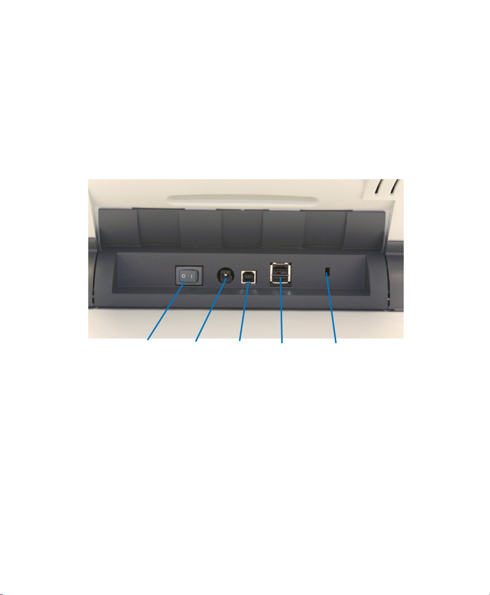
Back View
1. Power Switch — Turns the scanner on and off.
2. Power Port — Connects the power cord to the
scanner.
3. USB Port — Connects the scanner to the PC.
4. Not Used
5. Security Lock Port — Connects a security lock to
the scanner.
Operator’s Guide 21

Chapter 2: Scanner Basics
Locking the Scanner
Locking the Scanner
A security lock port is available if you want to secure your
scanner. You can purchase a standard security lock (as
shown above) at an office supply store.
1. Insert the lock into the back of the scanner and turn
the key to lock the scanner in place.
2. Use the looped end of the cable to secure the cable
and scanner to a stationary place.
.
22 Scantron
i
NSIGHT 20 Scanner

Turning the Scanner On
Chapter 2: Scanner Basics
Turning the Scanner On
CAUTION:
Do not turn the scanner on before performing
the installation procedure covered in Chapter 3,
“Installation”. Doing so may result in incorrect drivers being loaded.
Press the switch on the back of the scanner to turn the
scanner on (l) or off (0).
After you turn on the scanner, wait for it to complete the
self-test. When the scanner is connected to the host PC
and the self-test completes, the green indicator light will
remain on and constant and the function window will
display “1”.
If the scanner is not connected to the host PC and the
self-test completes, the red indicator will be on and the
function window will be blank.
Operator’s Guide 23

Chapter 2: Scanner Basics
Scanner Positions
Scanner Positions
The iNSIGHT 20 scanner is equipped with a tilt feature
which allows the scanner to be tilted in two different
positions. Depending upon your scanning needs, you can
tilt the scanner body and adjust the output tray and
extender accordingly. The tilt feature also allows for
scanning in tight spaces when space is limited and for
compact storage when not in use.
The following photos show the angles the scanner can be
placed in. Simply press the tilt release button and tilt the
scanner body into a 25 or 60 degree angle.
25 degree position
This position is best for scanning batches larger than a few
sheets.
24 Scantron
i
NSIGHT 20 Scanner

Chapter 2: Scanner Basics
Scanner Positions
60 degree position
This position is best for storage or for scanning just a few
sheets. When scanning just a few sheets, do not use the
output tray as shown above. See “Output Tray Extender
Flat” on page 28 for the optimal output tray extender
position when scanning in the 60 degree position.
NOTE:
Heavier weight documents (e.g., 110-lb.) may not
feed properly when the scanner is positioned in the 60
degree position. If scanning heavy-weight documents,
use the 25 degree position.
IMPORTANT:
When using the tilt feature, be sure the scanner
cover is closed.
Operator’s Guide 25

Chapter 2: Scanner Basics
Tilting the scanner body
Tilting the scanner body
Press the Tilt release button and rotate the scanner body
into the desired position.
26 Scantron
i
NSIGHT 20 Scanner

Chapter 2: Scanner Basics
Top Piece
Bottom Piece
Adjusting the Output Tray and Output Tray Extender
Adjusting the Output Tray and Output Tray Extender
The output tray and the output tray extender can be used
in several positions. Different positions perform for
different needs. If the way you use your scanner is not
described in this section, experiment with different
positions to determine the one that best fits your needs.
NOTE:
For information on attaching these components to
the scanner, see “Attaching the Output Tray and Output Tray Extender” on page 45.
Optimal Position
When scanning for data collection or when scanning large
batches of mixed documents, the scanner should be in the
25 degree position as shown below. The output tray and
output tray extender should be installed as shown and
adjusted just slightly longer than the scanned pages.
Installing the exit deflector will result in a more organized
and compact output stack.
IMPORTANT:
Notice that the output tray extender is comprised of two pieces (a top and a bottom). For best
results, slide the bottom piece out so that the entire
length of the output tray assembly is a little longer
than the sheets you are scanning.
Operator’s Guide 27

Chapter 2: Scanner Basics
Adjusting the Output Tray and Output Tray Extender
Output Tray Extender Flat
This position works well for scanning just a few
documents. It is recommended when using the scanner in
the 60 degree position. To remove the tray extender from
this position, press on the two side tabs and pull.
Output Tray Extender on Incline
This position also works well for small batches of
documents.
28 Scantron
i
NSIGHT 20 Scanner

Chapter 2: Scanner Basics
Adjusting the Output Tray and Output Tray Extender
Exit Deflector
You can often improve your document stacking
performance by using the exit deflector. To find the
optimal setup, experiment by scanning with the exit
deflector on and off.
The exit deflector is easily installed by snapping it into
place.
NOTE:
Remove the exit deflector before tilting the
scanner to the upright position (60 degree angle).
Operator’s Guide 29

Chapter 2: Scanner Basics
Adjusting the Input Tray Side Guides
Adjusting the Input Tray Side Guides
The input tray side guides can be moved in or out to
accommodate different document sizes. Adjust the side
guides just slightly wider than the documents you are
scanning.
30 Scantron
i
NSIGHT 20 Scanner

Starting and Stopping the Scanner
Before you start scanning, make sure the scanner is on and
ready for operation, which is indicated by the green
indicator light being on and constant.
Scanning is controlled by software developed for your
application. To start and stop scanning, refer to the
documentation provided with your application software.
NOTE:
Be sure that the documents in the input tray are centered in the tray and in the path of the paper present
sensor.
Chapter 2: Scanner Basics
Starting and Stopping the Scanner
Operator’s Guide 31

Chapter 2: Scanner Basics
Timing Marks
Document Preparation
Document Preparation
Data Collection
General Guidelines
• Remove all staples and paper clips before scanning.
Staples and paper clips on documents may damage the
scanner and documents.
• If the forms were folded, we recommend unfolding
them and laying them flat for 24 hours in a climate
controlled (60º to 80º F or 16º to 27º C and 40-60%
humidity) environment.
• Align the forms so that all sheets have the same
orientation.
• Jog (align by tapping on a hard surface) the forms on
the leading edge (form ID edge) and timing mark
edge.
• Ensure that the forms are placed into the input tray
with the front side down (because it is a bottom feed
scanner). Also ensure that the timing marks are on the
left side (both front and back) when you are facing the
Scantron logo.
32 Scantron
i
NSIGHT 20 Scanner

Chapter 2: Scanner Basics
Document Preparation
• Paper Types: Precision forms printed by Scantron
are recommended for best results. Self printed forms
using Scantron DesignExpertTM with the PrintFlexTM
option are also acceptable.
• Paper Weights: 60 - 90 lb., (24 - 35 lb. bond),
(89 - 133 g/m2)
• Minimum Document Size: 2.5" x 5.5" (6.4 x 14 cm)
• M
aximum Document Size:
8.5" x 14" (21.6 x 35.6 cm
)
Damaged Documents
Sheet repair is possible in many cases. A list of possible
repairs follows:
• If a sheet is folded or crumpled, it can be flattened by
placing a flat weight on it overnight.
• If a sheet has dark marks on it, you can erase them or
use correction tape to cover them up. If using liquid
correction fluid, be sure to allow it to dry thoroughly
before scanning as otherwise it can get on the imaging
guide and cause errors.
• If a sheet is torn you can use tape to repair it. Be sure
to verify that the form is read correctly if taping over
marks or the timing track.
NOTE:
Tape on a sheet may generate a multiple sheet
error that will be displayed in the software.
If you are unable to repair the damaged sheet, copy the
marks from the damaged sheet onto a new one.
NOTE:
Protective sleeves cannot be scanned for data collec-
tion because of the effect the sleeve has on calibration.
Document Imaging
General Guidelines
• Remove all staples and paper clips before scanning.
Staples and paper clips on documents may damage the
scanner and documents.
• Documents should be in good condition.
Operator’s Guide 33

Chapter 2: Scanner Basics
Document Preparation
• A batch of documents to be fed into the scanner for
document imaging must be arranged so the leading
edges of all documents are aligned and centered in the
input tray; this allows the feeder to introduce
documents into the scanner one at a time.
• Paper Types: The iNSIGHT 20 moves paper very
well and will handle virtually any type of paper that is
not abrasive or excessively stiff.
NOTE:
Chemically coated papers may cause more rapid
wear/swelling of the tires.
• Paper Inks: All inks on the paper must be dry before
scanning is started. This includes: standard offset
printing, inkjet printer, thermal transfer, handwriting
inks.
• Correction Fluids: Liquid Paper®, Tipp-Ex®, Witeout®, and other similar correction fluids must be dry
before scanning is started. If not fully dry, correction
fluid can get on the imaging guides and cause errors.
• Paper Weights: 9 lb. bond to 110 lb. index (34 to
200 g/m2 kg)
• Minimum Document Size: 2.5" x 2" (6.4 x 5.1 cm)
• Maximum Document Size: 8.5" x 34"
(21.6 x 86.0 cm)
Damaged Documents
Torn, damaged, or crushed pages can be transported
successfully through the scanner. However, no scanner
can transport every possible type of damaged paper.
• If in doubt about whether a specific damaged
document can be transported through the scanner,
place the document in a clear protective sleeve.
Sleeved documents should be manually fed, one at a
time, while lifting the gap release lever. (Do not use
protective sheets for data collection scanning.)
• When scanning documents in a clear protective sleeve,
the input tray guides must be adjusted to
accommodate the width of the sleeve.
34 Scantron
i
NSIGHT 20 Scanner

Scanning Your Documents
Place the documents you want to scan into the input tray
of the scanner with the front side down (because it is a
bottom feed scanner).
Chapter 2: Scanner Basics
Scanning Your Documents
Automatic Feeding
To scan a batch of documents, follow the guidelines for
size, type, quantity, etc., as previously described in
“Document Preparation” on page 32.
CAUTION:
1. Align (jog) the leading edges of the stacked docu-
2. For data collection also align (jog) the timing mark side
3. For all documents, position the documents face down
Operator’s Guide 35
Remove all staples and paper clips before scanning. Staples and paper clips in documents may damage the scanner and the documents.
ments.
of the stacked documents.
with the leading edge centered in the automatic
document feeder.

Chapter 2: Scanner Basics
Timing Marks
Scanning Your Documents
NOTE:
For
data collection
, ensure that the timing
marks (both front and back of sheet) are on the
left side when you are facing the Scantron logo.
4. Adjust the input tray side guides.
5. Adjust the output tray position, if necessary.
6. Pull out the output tray extender, if necessary.
7. Start scanning.
Single Feeding
Follow the guidelines for document size, type, weight,
quantity, etc. Position the document face down with the
leading edge centered in the automatic document feeder,
36 Scantron
adjust the input tray side guides if necessary, then start
scanning.
i
NSIGHT 20 Scanner

Indicator Light
Indicator Light
Chapter 2: Scanner Basics
Indicator Light
The indicator light provides information on the current
state of the scanner.
This light… indicates…
Flashing green scanner is powering up,
busy, or in power saver
mode.
Steady green scanner is ready to scan.
Steady red scanner error, such as
the scanner is not
connected to the host
computer or the scanner
cover is open.
Operator’s Guide 37

Chapter 2: Scanner Basics
Lamps
Lamps
Software Warm up Shut off
Default Lamp Shut Off Period
The default shut off period for the lamps is 15 minutes.
The iNSIGHT 20 scanner reverts to this default each time
it is powered up.
Software Lamp Warm Up and Shut Off Periods
Lamp warm up and shut off periods vary depending on
the software that you are using. See the table below:
• ScanTools Plus
• associated data collection diagnostic software
• Click&Scan
• Scanner Validation Tool
(SVT) document imaging software
NOTE:
5 minutes 240 minutes
10 seconds 0 to 240 minutes based
on Power Saver setting
in Device Settings
If you wish to shut off the lamps sooner than 240
minutes after running a ScanTools Plus application,
simply run Click&Scan or SVT with the Power Saver
Device Setting set to the desired shut off time.
38 Scantron
i
NSIGHT 20 Scanner

Clearing Document Jams
Scanner Cover
Release
Chapter 2: Scanner Basics
Clearing Document Jams
1. Remove any documents from the input tray area.
2. Lift up the scanner cover release to unlatch the
scanner cover.
3. Pull up to open the scanner cover.
4. Locate the jammed document and remove it, being
sure to clear any paper shreds or pieces left behind.
Operator’s Guide 39

Chapter 2: Scanner Basics
Clearing Document Jams
5. Lower the scanner cover and press it down firmly so
that both sides latch.
40 Scantron
i
NSIGHT 20 Scanner

In this chapter:
Selecting a Good Location . . . . . . . . . . . . . . . . . page 42
Attaching the Input Tray. . . . . . . . . . . . . . . . . . . page 44
Installing the iNSIGHT 20 and iNSIGHT 30 Drivers
and Scanner Utilities Software . . . . . . . . . . . . page 48
Getting Ready to Scan. . . . . . . . . . . . . . . . . . . . . page 58
Handling the “Recalibrate the scanner”
Message . . . . . . . . . . . . . . . . . . . . . . . . . . . . . . . page 75
Uninstalling iNSIGHT 20 and iNSIGHT 30 Drivers
and Scanner Utilities Software . . . . . . . . . . . . . . page 76
Updating the iNSIGHT 20 and iNSIGHT 30 Drivers
and Scanner Utilities Software . . . . . . . . . . . . . page 78
Chapter 3:
Installation
This chapter covers scanner setup and software
installation. We recommend that you review the
information in Chapter 2, “Scanner Basics”, before
proceeding with this chapter. Doing so will help ensure
your success in scanning during setup and for production.
3
Registering Your Scanner
Registering your scanner takes very little time and ensures
that you receive all pertinent information regarding
product and software upgrades. For information on
registering your product, see “Registering Your Product”
on page 117.
Product Support and Services
If you encounter difficulties setting up or operating your
scanner, there are a number of places to get the needed
information to resolve your difficulty. For information on
the support services that are available, see Chapter 4,
“Product Support and Services”.
Operator’s Guide 41

Chapter 3: Installation
Selecting a Good Location
Selecting a Good Location
To place your scanner in a good location, observe these
requirements:
• Air quality. Keep in mind that a scanner works better
and lasts longer when it is not exposed to a lot of dust.
• Computer hookup. Place the scanner within 6 feet of
the computer to which it is to be connected.
• Flooring. Try to find a location for the scanner that is
not carpeted. Most types of carpeting introduce static,
which might interfere with the way the scanner
operates.
• Humidity. Use the scanner in a location having 40%
relative humidity. If sheets have been in very wet or
dry conditions, keep them in an atmosphere
controlled (60º to 80º Fahrenheit or 15º to 27º Celsius
with 40% humidity) environment for 24 hours before
you attempt to scan them.
• Electrical noise. Do not locate the scanner near a
generator or other type of large motor, such as an
elevator, an air conditioner, or a refrigerator that
produces electrical noise which might interfere with
the operation of the scanner.
• Phone access. Locate the scanner close to a phone
— in the same room if possible. Close phone access is
important if you need to call Scantron for assistance
with a scanning problem. Customer Support will
provide assistance over the phone.
• Power source. Place the scanner in a location that is
close to an electrical outlet that provides stable power.
The outlet must be properly grounded and meet
national and local electrical codes.
• Space. Find a location that allows you plenty of
working surface around the scanner. See “Scanner
Hardware Features” on page 3 for information on the
scanner’s size.
42 Scantron
i
NSIGHT 20 Scanner

Chapter 3: Installation
Selecting a Good Location
• Temperature. Place the scanner in an environment
that ranges between 60° and 85° Fahrenheit or 15º to
29º Celsius. Improper temperature conditions can
cause the scanner to read sheets incorrectly.
Operator’s Guide 43

Chapter 3: Installation
Pin
Hole
Attaching the Input Tray
Attaching the Input Tray
1. On one side of the scanner, place the pin into the hole
(see photo).
NOTE:
that the side guides have clearance.
It is necessary to tilt the tray forward somewhat so
2. Next, push the input tray gently but firmly toward the
other side, so that the pin on the other side has
clearance to fit in the hole on the other side.
3. Allow the input tray to rotate down into position.
44 Scantron
i
NSIGHT 20 Scanner

Chapter 3: Installation
Attaching the Output Tray and Output Tray Extender
Attaching the Output Tray and Output Tray Extender
This section covers attaching the output tray and output
tray extender. For information on how to adjust them, see
“Adjusting the Output Tray and Output Tray Extender”
starting on page 27.
Attaching the Output Tray (for use in the 25 degree position)
NOTE:
The output tray should not be used when scanning
in the 60 degree position. See “Output Tray Extender
Flat” on page 28 for the recommended setup for the
60 degree position.
NOTE:
The scanner can be used without the output tray
when scanning a few (five or less) sheets.
Slide the output tray along the center guide underneath
the scanner platform as shown below:
Attaching the Output Tray Extender
For larger scanning jobs, using the output tray extender is
recommended.
Operator’s Guide 45

Chapter 3: Installation
Output Tray Extender
Output Tray
Top Piece
Bottom Piece
Attaching the Output Tray and Output Tray Extender
1. Turn the output tray over and slide the output tray
2. Turn the output tray with extender right-side up and
extender along the rail of the output tray.
slide it under the scanner until it locks into place.
IMPORTANT:
Notice that the output tray extender is
comprised of two pieces (a top and a bottom).
For best results, slide the bottom piece out so that
the entire length of the output tray assembly is a
little longer than the sheets you are scanning.
46 Scantron
i
NSIGHT 20 Scanner

Chapter 3: Installation
Exit Deflector
Attaching the Output Tray and Output Tray Extender
Exit Deflector
When using the output tray extender and scanning smaller
documents or mixed sized documents, you can improve
your document stacking performance by using the exit
deflector. The exit deflector is easily installed by snapping
it into place.
NOTE:
Remove the exit deflector before tilting the
scanner to the upright position (60 degree angle).
Operator’s Guide 47

Chapter 3: Installation
Installing the iNSIGHT 20 and iNSIGHT 30 Drivers and Scanner Utilities Software
Installing the
i
NSIGHT 20 and iNSIGHT 30 Drivers and
Scanner Utilities Software
CAUTION:
ner to the PC.
NOTE:
The iNSIGHT 20 and iNSIGHT 30 Drivers and
Scanner Utilities software supports only one scanner
connected to the host computer at a time.
The iNSIGHT 20 and iNSIGHT 30 Drivers and Scanner
Utilities installation program installs the following
software:
• TWAIN Driver: The software utility program that
controls the scanner.
• Scan Validation Tool: A software program that
enables you to test the scanner’s document imaging
capabilities.
• Click&Scan: A software program that allows you to
perform document imaging tasks with just a few clicks
of your mouse.
• Calibration Utility: A software program that is used
during setup to calibrate the scanner for data
collection. After setup, this program should not be
used unless the scanner has been moved to a different
computer, the scanner has been exchanged for a new
one, or you are directed to do so by Scantron
Customer Support.
• Scanner Exerciser: A software utility program that
Customer Support uses to test the data collection
capabilities of the scanner.
NOTE:
Microsoft .Net Framework to function. The
installation routine will also install the .Net
Framework if it is not already installed.
Install the software
Some of the software above requires the
before
connecting the scan-
48 Scantron
i
NSIGHT 20 Scanner
Chapter 3: Installation
Installing the iNSIGHT 20 and iNSIGHT 30 Drivers and Scanner Utilities
Use the following procedure to install the software
and connect the scanner.
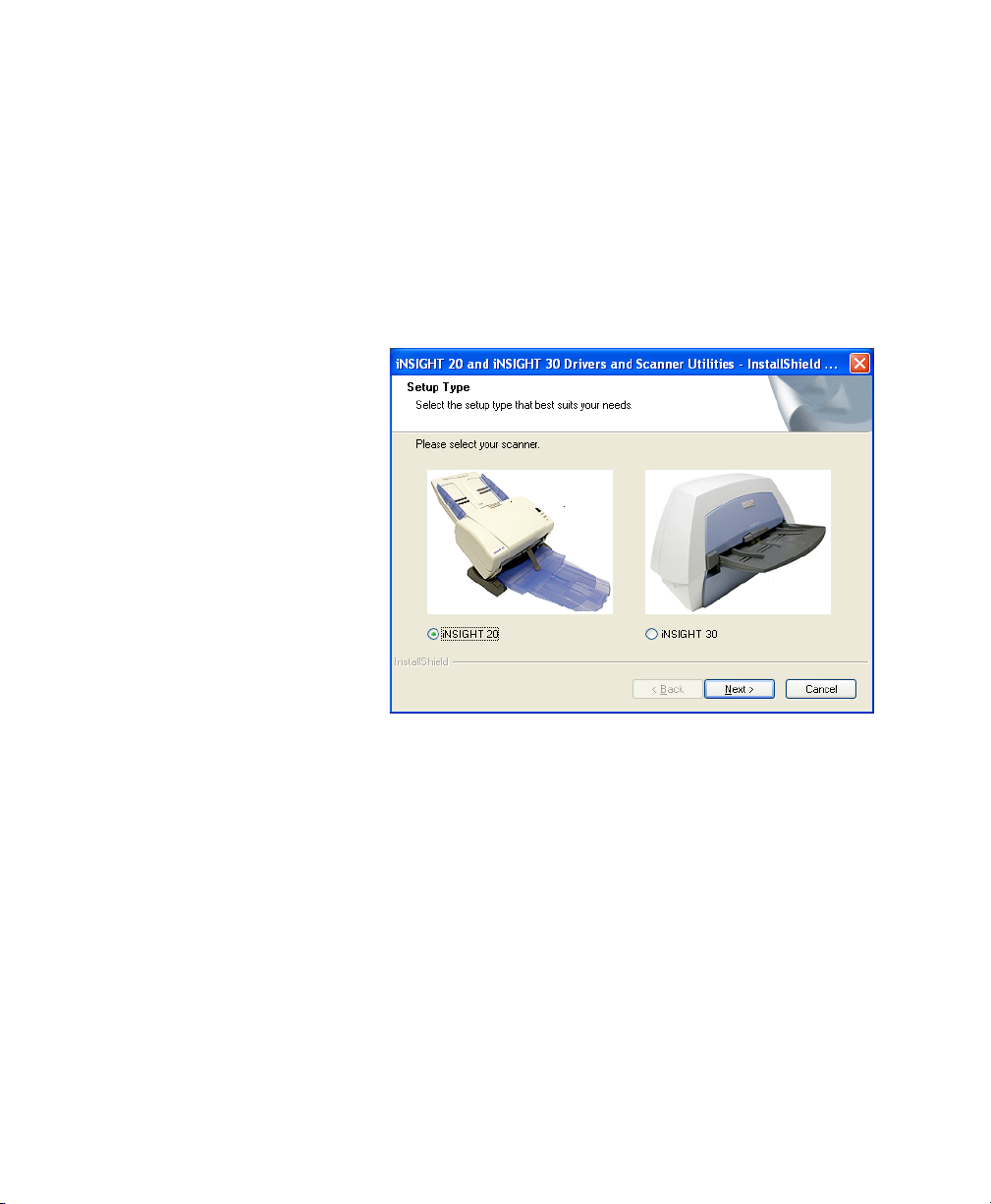
1. Insert the iNSIGHT 20 and iNSIGHT 30 Drivers and
Scanner Utilities CD into the CD-ROM drive.
2. Browse to your CD-ROM drive, then double-click
Setup.exe.
The Setup Type dialog box appears.
3. Select iNSIGHT 20 and click Next.
The Welcome dialog box appears.
Operator’s Guide 49

Chapter 3: Installation
Installing the iNSIGHT 20 and iNSIGHT 30 Drivers and Scanner Utilities Software
4. Click Next to continue. The Choose Destination
Location dialog box appears.
5. Accept the default location or enter a destination for
the program files in the text box. Click Next to
continue. The Select Program Folder dialog box
appears.
50 Scantron
i
NSIGHT 20 Scanner

Chapter 3: Installation
Installing the iNSIGHT 20 and iNSIGHT 30 Drivers and Scanner Utilities
6. Accept the default or enter a program folder in the
text box. Click Next to continue. The Setup Status
dialog box appears and displays the installation
progress.
NOTE:
If the Restarting Windows dialog box appears,
click Yes, I want to restart my computer now and
click OK to restart your computer. (Once the restart is
complete, the installation process will continue.)
7. When setup is complete, the following message box
appears:
8. Click OK to continue.
NOTE:
The following setup steps follow along with the
software installation program. They are included here
with additional information.
Connecting the Power Cord to the Scanner
Use only the power supply that was provided with your
Scantron iNSIGHT 20 Scanner. Do not substitute
another power supply model or another manufacturer’s
power supply.
After the drivers have been installed, use the following
procedure to connect the power supply and power cord to
the scanner. Make sure that the power outlet is located
within 5' (1.52 meters) of the scanner and is easily
accessible.
Operator’s Guide 51

Chapter 3: Installation
Taiwan
TW15GS2
North America
ME301P
Australia
Note: Places listed are a general guideline only.
China
Europe
MP5004A
Japan
M733F
V301C
United Kingdom, Ireland,
Hong Kong, Malaysia,
Singapore
M4206
AU10S2
Installing the iNSIGHT 20 and iNSIGHT 30 Drivers and Scanner Utilities Software
1. Select the appropriate AC power cord for your region
from the supply of power cords packed with your
scanner.
2. Attach the power cord for your power type to the
power supply.
52 Scantron
i
NSIGHT 20 Scanner

Chapter 3: Installation
Installing the iNSIGHT 20 and iNSIGHT 30 Drivers and Scanner Utilities
3. Plug the power cord output lead (attached to the
power supply) into the power port on the back of the
scanner.
4. Plug the power cord input lead (attached to the power
supply) into the wall outlet.
Connecting the USB Cable
CAUTION:
Operator’s Guide 53
If you have not installed the iNSIGHT 20 and
iNSIGHT 30 Drivers and Scanner Utilities
software, do that now before proceeding.

Chapter 3: Installation
B
A
Installing the iNSIGHT 20 and iNSIGHT 30 Drivers and Scanner Utilities Software
The USB cable supplied with your scanner has two
different ends.
1. Attach the B end of the USB cable to the scanner USB
port, located on the back of the scanner.
IMPORTANT:
The USB port may be covered by a
sticker. Remove the sticker to access the port.
2. Attach the A end of the USB cable to an open high
speed USB 2.0 port on your PC.
54 Scantron
i
NSIGHT 20 Scanner

Chapter 3: Installation
Installing the iNSIGHT 20 and iNSIGHT 30 Drivers and Scanner Utilities
Finalizing the iNSIGHT 20 Drivers and Scanner Utilities Software Installation
When the iNSIGHT 20 and iNSIGHT 30 Drivers and
Scanner Utilities software has been properly installed and
the USB cable and power connections have been made,
you can turn on the power to complete installation.
1. Turn on the power to the scanner.
Operator’s Guide 55

Chapter 3: Installation
Installing the iNSIGHT 20 and iNSIGHT 30 Drivers and Scanner Utilities Software
2. The scanner will go through a series of self tests, and
the indicator LED will light.
When the scanner is finished and ready to scan, the
indicator LED will stop flashing and stay green. When
this occurs, click Next to continue.
If the green LED indicator does not become a steady
green within several minutes, contact Scantron Customer Support as described in “Requesting Support”
on page 125.
3. The Wizard Complete dialog box appears. Click
Finish to complete driver and utility installation.
56 Scantron
i
NSIGHT 20 Scanner

Chapter 3: Installation
Installing the iNSIGHT 20 and iNSIGHT 30 Drivers and Scanner Utilities
4. The Select Option dialog box appears.
Do not click Exit. Continue following the steps in the
next section to get ready to start scanning.
Operator’s Guide 57

Chapter 3: Installation
Getting Ready to Scan
Getting Ready to Scan
Once the hardware is connected and the drivers are
installed, perform the following to get ready to scan
documents:
• Step 1: Calibrating Your iNSIGHT 20 (page58)
• Step 2: Running the Document Imaging Test
If your scanner came bundled with ScanTools Plus data
collection software, you should also perform the following
three steps:
• Step 3: Installing ScanTools Plus Software (page68)
• Step 4: Configuring the Scanner (page68)
• Step 5: Running the Data Collection Test (page69)
Step 1: Calibrating Your iNSIGHT 20
(page64)
CAUTION:
The iNSIGHT 20 Calibration program should
only be run for the following reasons:
• upon initial installation
• you move the scanner to a different computer
• your scanner is exchanged for a new one.
• you are directed to by Scantron support
NOTE:
You can run only one of the following programs at a
time because they use the same driver:
• Scan Validation Tool
• Click&Scan
• ScanTools Plus
•the iNSIGHT 20 Scanner Utilities.
The calibration program does two things to ensure that
the scanner will read production data collection forms
properly:
• Checks the black, gray, and white areas of the
sheet to create a calibration table that maps the
256 gray levels to the 16 levels used for data collection.
58 Scantron
i
NSIGHT 20 Scanner

Chapter 3: Installation
Getting Ready to Scan
• Targets the location of the black dots for position-
ing purposes.
The calibration program reads Normalization &
Calibration sheets (supplied with the scanner, see photo
below).
NOTE:
The part number for a box of 80 Normalization &
Calibration Sheets is 342 760 014.
1. Close all other programs.
Operator’s Guide 59

Chapter 3: Installation
Getting Ready to Scan
2. From the screen shown below, click Run iNSIGHT
20 Calibration.
NOTE:
If you are no longer at the above screen, you can
run the calibration program by going to your
Windows desktop and selecting
StartProgramsScantroniNSIGHT 20
Scanner UtilitiesCalibration Utility.
3. The following dialog box appears:
4. Click Calibrate. The Step 1 of 2... dialog box appears.
5. Place a stack of Normalization & Calibration Sheets
(part number 202 502 043) into the input tray, printed
side down, so that the words “Normalization &
60 Scantron
i
NSIGHT 20 Scanner

Chapter 3: Installation
Getting Ready to Scan
Calibration Sheet” enter the scanner first, as shown in
the photo below.
NOTE.
Corner turned to show printed side only.
6. Click OK.
I
f the lamps have been off, the
Lamps warming up...
dialog box appears. Please wait while the lamps warm up
7. When the lamps have warmed up, the Calibrating
front/top camera... dialog box appears and scanning
begins. Please wait while the software and scanner
performs front side calibration.
8. If you get an error message (like the one below), use
the table below to take the necessary corrective action.
When you are done, click Resume.
Operator’s Guide 61
.

Chapter 3: Installation
Getting Ready to Scan
Error What To Do
Jam Open scanner, remove obstruction and rescan.
Multi-feed Open scanner, remove sheets and rescan.
Calibration sheet not
recognized
Check for proper calibration sheet and that it is
aligned properly. Rescan.
Image quality error Clean imaging guide(s) or rollers and rescan.
Calibration separation error Clean rollers and rescan.
9. When calibration for the front side is complete, the
Verifying calibration... dialog box appears and the
scanner will scan more sheets. Please wait while
verification takes place.
If the input tray empties and the Input hopper
empty message box appears, take the sheets from the
output tray, tap them on a hard surface to align them,
then place them back in the input tray the same way
you last loaded them. When you are ready, click Retry.
10. When front side calibration is complete, the Step 2 of
2... dialog box appears.
Place a stack of Normalization & Calibration Sheets
(part number 202 502 043) into the input tray, printed
side up, and so that the words “Normalization & Cali-
62 Scantron
i
NSIGHT 20 Scanner

Chapter 3: Installation
Getting Ready to Scan
bration Sheet” enter the scanner last (as shown in the
photo below).
Click OK.
11. The Calibrating back/bottom camera... dialog box
appears. Please wait while the software performs back
side calibration.
12. When back side calibration is complete, the Verifying
calibration... dialog box appears and the scanner will
scan more sheets. Please wait while verification takes
place.
If the input tray empties and the Input hopper
empty message box appears, take the sheets from the
output tray, tap them on a hard surface to align them,
then place them back in the input tray the same way
you last loaded them. When you are ready, click Retry.
Operator’s Guide 63

Chapter 3: Installation
Getting Ready to Scan
13. When verification is completed successfully, the
Calibration complete dialog box appears. Calibration
is now complete. Click OK to continue.
14. The Select Option dialog box reappears.
If you are recalibrating, the process is complete; click
Exit to continue.
If this is your initial installation, continue on to “Step
2: Running the Document Imaging Test” on page 64.
Step 2: Running the Document Imaging Test
NOTE:
You can run only one of the following programs at a
time because they use the same driver: Scan Validation
Tool, Click&Scan, ScanTools Plus, and the iNSIGHT
20 Scanner Utilities.
1. The next step is to verify that the scanner can perform
document imaging tasks. To do this, from the
switchboard shown below, click Run Document
Imaging Test.
NOTE:
If you are no longer at the above screen, start the
Scan Validation Tool by selecting
StartProgramsScantronDocument
ImagingScan Validation Tool.
64 Scantron
i
NSIGHT 20 Scanner

Chapter 3: Installation
Getting Ready to Scan
2. The Scan Validation Tool dialog box appears. Select
TWAIN and Scantron iNSIGHT 20 as shown. Click
OK.
3. The Connecting to Scanner message box appears,
indicating that it may take a few minutes to connect to
the scanner. Do not press any keys or perform any
mouse operations during this time.
Operator’s Guide 65

Chapter 3: Installation
Getting Ready to Scan
4. The Scan Validation Tool appears. Click the two-
image display button (shown in the margin).
5. Click the Setup button (shown in the margin).
66 Scantron
i
NSIGHT 20 Scanner

Chapter 3: Installation
Getting Ready to Scan
6. The main iNSIGHT 20 settings window appears.
a. Under Setting Shortcuts select Color Docu-
ment
b. Under Input document is, ensure that Two
Sided is selected.
c. Click OK.
7. The Scan Validation Tool window reappears. Place a
two sided color document in the input tray, then click
the Start Scanning button (shown in the margin).
The scanner will scan the document. If both sides of
the document display properly in the viewer, the scanner is ready for document imaging use. If you get an
error, contact Scantron Customer Support as
described in “Requesting Support” on page 125.
Operator’s Guide 67

Chapter 3: Installation
Getting Ready to Scan
Step 3: Installing ScanTools Plus Software
IMPORTANT:
Perform this step only if your scanner came
bundled with ScanTools Plus data collection software.
CAUTION:
You must have the iNSIGHT 20 and iNSIGHT
30 Drivers and Scanner Utilities installed before
installing ScanTools Plus.
Next, install ScanTools Plus data collection software. See
Chapter 2 of the ScanTools Plus User’s Guide (included with
your iNSIGHT 20 scanner) for instructions on how to
install the software.
Step 4: Configuring the Scanner
IMPORTANT:
bundled with ScanTools Plus data collection software.
CAUTION:
installed before you can configure the scanner.
1. Select StartProgramsScantronScanTools
Plus to start ScanTools Plus software. The ScanTools
Plus window appears.
Perform this step only if your scanner came
You must have the ScanTools Plus software
68 Scantron
i
NSIGHT 20 Scanner

Chapter 3: Installation
Getting Ready to Scan
2. Select ConfigureScanner Configuration... from
the ScanTools Plus menu. The Scanner Configuration
dialog box appears.
a. Select iNSIGHT 20 for the Scanner Model.
b. Make sure that Write Operations Log is selected.
c. Click the Auto Configure button.
If you get an error, contact Scantron Customer Support as described in “Requesting Support” on
page 125. Otherwise, click OK to complete scanner
configuration.
Step 5: Running the Data Collection Test
IMPORTANT:
bundled with ScanTools Plus data collection software.
NOTE:
time because they use the same driver:
• Scan Validation Tool
• Click&Scan
• ScanTools Plus
Operator’s Guide 69
Perform this step only if your scanner came
You can run only one of the following programs at a

Chapter 3: Installation
Getting Ready to Scan
•the iNSIGHT 20 Scanner Utilities.
In this section you will use ScanTools Plus software to
perform data collection.
1. If it is not already running, start ScanTools Plus by
selecting StartProgramsScantronScanTools
Plus. The ScanTools Plus window appears.
2. In the ScanTools Plus window, select 710 - Data
Collection Test in the Application combo box. This
will automatically load the correct selections for Data
file, Edit profile, Score profile, and Conversion profile.
NOTE:
If the 710 - Data Collection Test application is
not shown, it could be that the path is pointing to
a previously used directory. In the ScanTools
70 Scantron
i
NSIGHT 20 Scanner

Chapter 3: Installation
Getting Ready to Scan
program, select ConfigurePaths. For the
application path, browse to C:\Program
Files\Scantron\ScanTools Plus\Applications.
Click OK, then try to select the application again.
If this does not resolve the issue, contact Scantron
Customer Support as described in “Requesting
Support” on page 125.
3. Load the test forms:
a. Find the pack of 16 pre-slugged (answers filled in)
General Purpose Answer Sheets #223127 (pack
number 202-521-006).
These sheets have been marked with sample data.
The 710 - Data Collection Test sample
application is set up to collect only the Name data
from these sheets.
b. Jog (tap on hard surface) the sheets to align them.
c. Place the sheets into the input tray of the scanner
with the printed side down, and so that the three
Operator’s Guide 71

Chapter 3: Installation
Form ID Marks
Getting Ready to Scan
black rectangular (Form ID) marks enter the scanner first.
4. Scan the sheets by clicking Scan in the ScanTools Plus
window.
The sheets should scan. If they do not, recheck your
scanner installation. If you are unable to resolve the
difficulty, contact Scantron Customer Support as
described in “Requesting Support” on page 125.
5. When the scanner is done scanning, the following
dialog box appears indicating that the input hopper is
72 Scantron
i
NSIGHT 20 Scanner

Chapter 3: Installation
Getting Ready to Scan
empty. Click Stop to clear the dialog boxes so that you
can view the data file.
6. Select Data FileView in the ScanTools Plus menu
bar to review the data file. The data file appears.
7. Use the up and down buttons (shown in the margin)
next to the Serial Number text box to page through
the Name data for each sheet.
If correct data (for the Name field only) is present for
each sheet, the test is complete and the scanner is ready to
perform data collection tasks. For more information
regarding how to perform data collection projects
start to finish, refer to Chapter 2, Data Collection
Operator’s Guide 73

Chapter 3: Installation
Getting Ready to Scan
Basics, of the Data Collection and Document Imaging Guide
(included with your scanner).
If data appears incorrect or is missing, contact Scantron Customer Support as described in “Requesting
Support” on page 125.
Installation Complete
Installation is now complete. Please be sure to familiarize yourself with the rest of the information in this
guide.
74 Scantron
i
NSIGHT 20 Scanner

Handling the “Recalibrate the scanner” Message
Handling the “Recalibrate the scanner” Message
Scantron normally recommends calibrating the scanner
only upon initial setup or under the guidance of a
Scantron Customer Support Representative. However,
there are certain situations where you may get an error
message, similar to the one below, recommending that you
recalibrate the scanner.
The possible causes of this error message are:
• If calibration was unsuccessful.
• If you aborted the installation procedure before
calibration was completed.
• If you moved the scanner to a new host computer.
• If you swapped out a defective scanner for a new one.
Chapter 3: Installation
If one of these conditions applies to you, you will need to
recalibrate the scanner. To do this, follow the procedure
below:
1. Select StartProgramsScantroniNSIGHT 20
Scanner UtilitiesCalibration Utility.
2. Go to the section entitled “Step 1: Calibrating Your
iNSIGHT 20” on page 58, and follow the procedure
there to recalibrate the scanner.
Operator’s Guide 75

Chapter 3: Installation
Uninstalling iNSIGHT 20 and iNSIGHT 30 Drivers and Scanner Utilities Software
Uninstalling
i
NSIGHT 20 and iNSIGHT 30 Drivers and Scanner
Utilities Software
NOTE:
Perform the following steps only if you want to
uninstall the software.
If you want to uninstall the drivers and scanner utilities
software, it is important to do so in the correct order to
avoid leaving any empty program groups in the programs
menu. Use the following procedure:
1. Before uninstalling any programs, close all programs
and turn off the scanner.
2. Select StartSettingsControl PanelAdd or
Remove Programs. Wait for the list to populate.
3. Remove the Click&Scan software first. Select
Scantron iNSIGHT 20 - Click&Scan from the Add
or Remove Programs list then click Remove.
4. Next remove Scan Validation Tool (SVT) and the
driver. Selecting Scantron iNSIGHT 20 from the
Add or Remove Programs list and click Remove.
NOTE.
When the dialog comes up regarding removing
SVT components, select YES TO ALL.
5. Finally, remove the scanner utilities. Select Scantron
iNSIGHT 20 Scanner Utilities from the Add or
Remove Programs list and click Remove.
NOTE:
If you uninstalled the software in an order
different from that specified above, it is a simple
matter to remove the empty program groups:
a. Select the empty program group from the
Start menu (e.g. StartPrograms
ScantronDocument Imaging).
b. With the empty program group showing,
right-click and select Delete.
76 Scantron
i
NSIGHT 20 Scanner

Uninstalling iNSIGHT 20 and iNSIGHT 30 Drivers and Scanner Utilities
Uninstalling ScanTools Plus Software
Chapter 3: Installation
IMPORTANT:
This procedure is applicable only if your scanner came bundled with ScanTools Plus data collection
software.
If you want to uninstall the ScanTools Plus software, see
Chapter 2 of the ScanTools Plus User’s Guide (included with
your iNSIGHT 20 scanner) for instructions.
Operator’s Guide 77

Chapter 3: Installation
Updating the iNSIGHT 20 and iNSIGHT 30 Drivers and Scanner Utilities Software
Updating the
i
NSIGHT 20 and iNSIGHT 30 Drivers and
Scanner Utilities Software
CAUTION:
software update because the new firmware is loaded
into the scanner upon power up. Failure to turn off
the scanner during the update will result in the old
firmware remaining resident in the scanner.
To update the iNSIGHT 20 and iNSIGHT 30 Drivers and
Scanner Utilities software use the following procedure:
1. Insert the iNSIGHT 20 and iNSIGHT 30 Drivers and
Utilities CD into the CD-ROM drive of the host
computer. The setup program starts automatically.
NOTE:
StartRun from the Windows desktop. Browse
to the CD-ROM drive, then double-click on
setup.exe.
The Select Option dialog box appears.
It is important to turn the scanner off during the
If the CD does not start automatically, select
NOTE:
If you uninstalled the software prior to
performing the update, a complete re-installation
will be performed. See “Installing the iNSIGHT
78 Scantron
i
NSIGHT 20 Scanner

Chapter 3: Installation
Updating the iNSIGHT 20 and iNSIGHT 30 Drivers and Scanner Utilities
20 and iNSIGHT 30 Drivers and Scanner Utilities
Software” on page 48 for instructions on a
complete re-installation.
2. Click Update/Repair iNSIGHT 20 and iNSIGHT
30 Drivers and Scanner Utilities. The Question
message box appears.
3. Click Yes to remove the current version and install the
update from the CD. A message box appears asking
you to wait while the update is taking place.
4. When the update routine has completed removing the
outdated components, the Welcome dialog appears.
5. From this point forward, the update procedure is
identical to the original installation procedure. See
“Installing the iNSIGHT 20 and iNSIGHT 30 Drivers
and Scanner Utilities Software” on page 48 beginning
with step 2 for detailed instructions on how to
complete the update process.
6. When the Select Option dialog box reappears, the
update is complete. There is no need to re-calibrate
the scanner, or to run the document imaging test.
NOTE:
If, for some reason, the calibration file is missing
when you attempt to exit the Select Option dialog
box, you will be prompted to run the calibration
program. You should do so if you receive that
prompt.
Operator’s Guide 79

Chapter 3: Installation
Updating the iNSIGHT 20 and iNSIGHT 30 Drivers and Scanner Utilities Software
NOTES
80 Scantron
i
NSIGHT 20 Scanner

In this chapter:
Maintenance Schedule. . . . . . . . . . . . . . . . . . . . . page 83
Supplies and Consumables . . . . . . . . . . . . . . . . . page 85
Opening and Closing the Scanner Cover. . . . . . page 87
Running a Transport Cleaning Sheet . . . . . . . . . page 89
Cleaning the Rollers and Transport . . . . . . . . . . page 90
Cleaning the Separator Module . . . . . . . . . . . . . page 91
Cleaning the Feed Module . . . . . . . . . . . . . . . . . page 92
Cleaning the Imaging Guides . . . . . . . . . . . . . . . page 94
Cleaning the Ultrasonic Multi-feed Detector. . . page 95
Removing and Replacing the Separator Module . . . . . . .
. . . . . . . . . . . . . . . . . . . . . . . . . . . . . . . . . . . . . . . page 97
Replacing the Separator Module Tires . . . . . . . . page 99
Replacing the Pre-Separation Pad . . . . . . . . . . page 101
Adjusting the Pre-Separation Roller Tension. . page 103
Removing and Replacing the Feed Module . . . page 105
Replacing the Feed Module Tires. . . . . . . . . . . page 108
Chapter 4:
Maintenance
4
Precautions
Operator’s Guide 81
Cleaning your scanner and preventative maintenance on a
regular basis is required to ensure the best possible data
quality. Some guidelines follow:
• Do not use canned/compressed air as this can force
dust into difficult to clean areas.
• Use only the recommended cleaning supplies.
• Using unapproved cleaning fluids or solvents may
damage the foam tires.
• Some document types generate more paper dust and
debris and may require more frequent cleaning than
recommended.
• Some debris from the foam tires on the feed and
separator modules is normal. Tire debris does not
always mean that the tires are worn or damaged. After
cleaning, inspect the tires for wear and replace the
separator module or feed module if necessary.

Chapter 4: Maintenance
• When cleaning rollers, use an emulsiclean wipe and
allow the rollers to dry completely before scanning.
• When cleaning tires, use a slightly damp staticide wipe
and allow the tires to dry completely before scanning.
• In addition to the recommended cleaning supplies,
you may use a vacuum cleaner to remove debris from
the scanner.
• If a difficulty persists after performing the
maintenance recommended in this manual, call
Scantron Customer Support as described in
“Requesting Support” on page 125.
82 Scantron iNSIGHT 20 Scanner

Maintenance Schedule
Procedure Interval What to Use
Chapter 4: Maintenance
Maintenance Schedule
Use the following table as a guide to routine maintenance.
Usage figures are not guaranteed. Customer-operating
environments, document type, the condition of
documents being scanned, and not following the
recommended cleaning and replacement procedures, can
cause the life of the consumables to vary.
Clean separator module
tires
Clean feed module tires As required
Clean drive rollers and
transport area
As required
depending on the
type of scanning
being performed.
depending on the
type of scanning
being performed.
As required
depending on the
type of scanning
being performed.
Use staticide wipe (part number
830 9783) -- slightly damp.
Allow to air dry before
scanning.
Use staticide wipe, (part number
830 9783) -- slightly damp.
Allow to air dry before
scanning.
Run transport cleaning sheet,
(part number 896 2201). If
required, use emulsiclean wipe,
(part number 137 4966) on red
and white rollers. Allow to air
dry.
CAUTION:
DO NOT USE THE
EMULSICLEAN WIPE
ON THE GRAY FOAM
TIRES.
Clean imaging guides Daily Use staticide wipe, (part number
830 9783) -- slightly damp. Wipe
with a dry staticide wipe before
scanning.
Operator’s Guide 83

Chapter 4: Maintenance
Maintenance Schedule
Procedure Interval What to Use
Clean paper path Daily Use emulsiclean wipe, (part
number 137 4966) in transport
area and on red and white
rollers. Allow to air dry.
CAUTION:
DO NOT USE THE
EMULSICLEAN WIPE
ON THE GRAY FOAM
TIRES.
Replace (separator
module and feed
Every 100,000
documents scanned
module) tires
Replace separator
module
Replace pre-separation
pad
Every 200,000
documents scanned
Every 250,000
documents scanned
Replace feed module Every 500,000
documents scanned
NOTE:
Scantron scanners use replaceable tires than can feed
a wide range of document types, sizes and thicknesses.
Tire life and performance will vary based on the
document set, the frequency of cleaning of the
transport and tires, and following the recommended
schedule for changing tires. You should change the
tires if you notice an increase in multiple feeds,
stoppages, or a decrease in feeder performance that is
not resolved by the above cleaning procedures.
NOTE:
Certain paper types (such as carbonless paper or
newsprint), failure to clean regularly, and/or use
of non-recommended cleaning solvents can shorten
tire and roller life.
Use tires from feed roller kit
(part number 832 0806) or
consumables kit (part number
20190).
Use separation module, (part
number 186 0089).
Use part from feed roller kit
(part number 832 0806).
Use feed module (part number
192 9991).
84 Scantron
i
NSIGHT 20 Scanner

Supplies and Consumables
See “Ordering Supplies” on page 133 for information on
how to order supplies.
Supplies/Consumables Purpose Part Number
Chapter 4: Maintenance
Supplies and Consumables
Consumables Kit (12 feed
tires, 1 pre-separation pad, 50
transport cleaning sheets, 24
Provides commonly needed
wear parts and cleaning
supplies
20190
emulsiclean wipes, 144
staticide wipes)
Feed Roller Kit (12 feed tires,
1 separator module)
Replaces feeder consumable
components.
832 0806
Separation Module (with tires) Replaces separation module. 186 0089
Feed Module (with tires) Replaces feed module. 192 9991
Transport Cleaning Sheets
(50)
Emulsiclean Wipes (24) Use for cleaning the upper
Use to clean the drive rollers
and transport area.
896 2201
137 4966
and lower transport areas. Do
NOT use on the gray foam
tires or imaging guides.
Staticide Wipes (24) Use moist for cleaning the
830 9783
imaging guides. Use slightly
damp for cleaning the gray
foam tires. Use dry for drying
the transport area and imaging
guides after cleaning.
Calibration Sheets Use to recalibrate the scanner
342 760 014
for data collection after
replacing imaging guides or
moving to a different
computer.
Relocation Kit (1 box) Box for shipping scanner. 843 2783
Operator’s Guide 85

Chapter 4: Maintenance
Supplies and Consumables
IMPORTANT:
• Staticide wipes contain isopropanol which can cause
eye irritation and dry skin. Wash your hands with soap
and water after performing maintenance procedures.
Refer to the Material Data Safety Sheet (MSDS) for
more information. See below.
• Emulsiclean wipes contain sodium lauryl ether sulfate
and sodium silicate which can cause eye irritation.
Refer to the MSDS for more information. See below.
• Do not use canned/compressed air.
• Allow all tires and rollers to dry completely before
using the scanner.
• Do not use cleaners on hot surfaces. Allow surfaces to
cool to ambient temperature before use.
Material Safety Data Sheets (MSDS)
Material Safety Data Sheets (MSDS) for chemical
products are available on the Scantron Support Web site at
www.scantron.com/support. When accessing the
MSDSs from the Web site, you will need the part number
for the part or consumable. See “Supplies and
Consumables” on page 85 of this guide for a list of
consumables and their part numbers.
86 Scantron
i
NSIGHT 20 Scanner

Opening and Closing the Scanner Cover
Scanner Cover
Release
1. Power down the scanner if desired.
NOTE:
It is sometimes helpful to have the lamps on
when cleaning the imaging guide areas.
2. Remove any documents from the feeder area.
3. Place the scanner in the 25 degree position. See
“Tilting the scanner body” on page 26 for information
on how to do this.
4. Pull the scanner cover release lever and the scanner
cover up.
Chapter 4: Maintenance
Opening and Closing the Scanner Cover
Operator’s Guide 87

Chapter 4: Maintenance
Opening and Closing the Scanner Cover
5. When you finish cleaning the scanner or replacing a
part, press down firmly on scanner cover as shown so
that both sides latch.
88 Scantron
i
NSIGHT 20 Scanner

Running a Transport Cleaning Sheet
NOTE:
The scanner must be closed and powered on to run a
transport cleaning sheet.
1. Remove the wrapping from the Transport Cleaning
Sheet.
2. Adjust the side guides to fit the cleaning sheet.
3. Place a transport cleaning sheet in the input tray
(adhesive side up) in portrait orientation.
4. Using your scanning application, scan the transport
scanning sheet.
5. After the transport cleaning sheet is scanned, turn it
over and scan it again.
6. Repeat this procedure, if necessary until all residue is
removed from the drive rollers. If you are unable to
remove all residue from the drive rollers using the
transport cleaning sheet, perform the procedure
described in “Cleaning the Rollers and Transport” on
page 90.
Chapter 4: Maintenance
Running a Transport Cleaning Sheet
7. When a transport cleaning sheet gets very dirty,
discard it and use a new one.
8. When you are done running transport cleaning sheets,
open the scanner and check that the imaging guides
are clean. If necessary, clean the imaging guides as
described in “Cleaning the Imaging Guides” on
page 94.
Operator’s Guide 89
 Loading...