


HARD-WIRED CONTROL
PANEL
INSTALLATION AND PROGRAMMING GUIDE

Introduction
The 601/602 Alarm Control Panel is a fully programmable six zone Alarm
Control Panel designed specifically for domestic and small commercial installations.
A basic system comprises an Alarm Panel that houses the system electronics,
power supply, battery, and speech communicator (if fitted). On the 601 a
numeric keypad and row of Light Emitting Diodes (LEDS) allow the user and
installer to operate the system. The 602 has no keypad or displays except for a
Power LED. The user controls the system from a 625 remote keypad.
The 601/602 can work with all types of intruder alarm detector.
In addition, the 601/602 control panels can take the
Communicator: a small digital recorder that can be fitted within the panel. The
660 can be programmed to call up to four telephone numbers in the event of
an alarm, and deliver up to four recorded speech messages (refer to the 660
Installation and Programming Guide).
Before installing a 601/602 make sure you are fully familiar with the functions
of the panel and the various system plans and detectors described in this manual.
660 Speech
Introduction
1
496219 Issue 1

Facilities
Tamper
Arm
Lid screw
Zone LEDs
Write-on Label
for zone descriptions
Power LED
Armed LED
Illuminated
Keypad
Tamper LED
Alarm Panel. Figure 1 shows the 601 with its controls and displays.
Access Codes. The user controls the panel by means of four-digit access
codes. The user can store eight different codes plus a separate duress code in
Introduction
the panel, and change each one from the keypad.
The engineer must use a separate four digit code to start programming. The
engineer can change this code when the panel is unset.
Anti-Tamper. Anti tamper wiring protects the complete system. Connect all
tamper circuits in series to protect each zone. If the panel detects a tamper it
gives a tone from the internal sounder and flashes a warning LED when unset, or gives a full alarm when set.
Arm/Disarm Status. You can program the panel to leave the Armed LED off
when the panel is set. This allows the user to hide the fact that the panel is
armed.
Auxiliary Power. A 12V output provides power for detectors. The output can
provide up to 230mA quiescent.
Figure 1. 601 Displays and Controls
Chime. The panel gives a tone when activated by a detector while un-set.
Chime is only available for Normal Alarms, Entry Route zones, and Entry/Exit
zones.
2
496219 Issue 1

2-Ply Entry Timer. You can program the panel to give a 30 second internal
alarm if the user over-runs the programmed entry time. The user must unset
the panel before the warning ends, or the panel will give a full alarm.
Entry Route. The panel can be programmed to inhibit detectors on the route
between the final door and the keypad during the entry time.
Duress code. When the user enters a duress code, the panel sets or unsets,
and also triggers a PA output for remote communications.
Entry/Exit Times. You can program entry and exit delays independently. Each
can be up to 60 seconds long.
Entry/Exit Zones. You can program any zone as an Entry/Exit zone. Activating
an Entry/Exit zone when the panel is set starts the Entry timer. The user must
enter their Access Code before the timer expires or the panel will raise an
alarm.
External Bell. The panel can be connected to a Self Activated Bell (SAB) using
standard bell cable. The SAB draws power from the panel, and contains an
internal battery that will operate the sounder if intruders cut the supply. The
maximum current available is 500mA. The trigger for a SAB is negative applied
in alarm.
Introduction
You can program a delay between a detector being activated and the panel
triggering the bell, and also the length of the time the panel continues to
operate the external bell.
Full Set Exit Mode. When programmed for ‘Final Door’ exit mode the user
must enter their access code and close the final door. The panel sets when the
door closes. When programmed for ‘Timed or Terminate’ exit mode, the panel
starts the Exit timer when the user enters their access code. At the end of the
programmed exit time the panel sets. If a terminate button is fitted, the user
can press that to cut short the exit timer and set the system.
Keyswitch. The user can full set, part set, unset, or reset the panel using a
keyswitch. For this use a three position keyswitch. The panel has programming
options for momentary or fixed position keyswitch operation.
Loading Defaults. You can restore the panel to its factory default program by
using a programming command. See ‘Programming - Restore Factory
Defaults’ for more details.
Omit. You can program the panel to let the user omit individual zones, see
Zone Attributes below for more information.
Outputs. The panel provides open collector transistor outputs labelled Bell,
Strobe and OP1. OP1 can be programmed for one of the following options:
3
496219 Issue 1

a) PIR Set Latch. When a zone connects to more than one detector the
panel cannot identify which detector in the zone caused an alarm. To
help identify which detector caused an alarm connect the programmable
output to the Latch input of all detectors in the zone. When programmed for Set Latch the panel makes the output active at the end of
the exit time, resetting the detectors. When a detector causes an alarm,
the panel deactivates the output. This latches the indicator of the detector that caused the alarm, and inhibits all the other detectors connected
to the zone. The panel also deactivates the output when in Day mode.
b) Shock sensor. Stand-alone shock sensors normally latch when activated.
You can make the panel reset the sensors by connecting a programmable output to their positive supply. The panel deactivates the output for
six seconds at the start of the exit time, clearing any latched devices.
c) Strobe. Used to trigger an external strobe when a detector causes an
alarm.
d) Internal alarm. The panel activates this output whenever it triggers the
internal speaker.
Part Set. When part set the panel responds only to detectors that are programmed as part set zones. You can program the panel with the following
options:
• Part set Alarm response can be full or internal only.
• The Entry/Exit zone can be programmed to become an Instant
• The Entry Route zone can be programmed become an an
Introduction
Personal Attack. The user can trigger a PA alarm either by pressing a PA but-
ton, or by pressing keys 1 and 3 together on the panel or remote keypad. You
can program the panel to respond to a PA by:
In addition, you can disable the PA buttons on the remote keypads through
programming.
Rearm Mode. You can program the panel to re-arm itself after raising an
alarm. The options are: never (keypad reset only), once, twice, three times or
always.
• Exit mode can be Instant Set, Silent Set, or the same as Full Set.
• EITHER giving either a full alarm.
• OR remaining silent during a PA alarm if the panel is connected to
Alarm zone during part set, or remain as an Entry/Exit.
Entry/Exit zone during part set, or remain as an Entry Route.
a 660 Speech Communicator.
Note: This feature does not rearm the speech communicator output.
Remote Keypads. The 601/602 can support up to two 625 remote keypads.
The keypads provide the same keys, displays and sounders as the main panel
4
496219 Issue 1

(see Figure 2). Note that you can disable the Personal Attack signal from the
Keypad Closed
Keypad Open
Write zones
here
Zones
keypad during programming.
Note: The 602 is supplied complete with one 625 remote keypad.
Fig 2. 625 Remote Keypad
Sounders. The panel uses a loudspeaker fitted inside the case to give alarm
and entry/exit tones. You can connect a remote boxed speaker to the speaker
terminals.
System Reset. When delivered from the factory the panel allows the customer
to reset it after an alarm. If necessary you can program it for engineer only
reset.
Zone Types. You can program any zone as one of seven types. Each type
operates as follows:
a) Normal Alarm causes an instant alarm when the panel is set.
b) 24 Hour Zone causes an instant alarm whether the panel is set or un-set.
The alarm is internal only when the panel is un-set.
c) Entry Route Zone causes a full alarm if the panel is set. However, if the
entry timer is running then the panel inhibits this zone. Use for detectors
between the entry door and the panel.
d) Entry/Exit Zone starts the entry timer if the panel is set.
e) PA Zone causes an instant alarm whether the panel is set or un-set.
f) Fire Zone causes an instant alarm whether the panel is set or un-set, and
pulses any external sounder.
Introduction
g) Technical Alarm causes an instant alarm whether the panel is set or un-
set, and triggers the internal sounder.
5
496219 Issue 1

Zone Attributes. You can change the way each zone type behaves as follows:
a) Chime. The panel gives a tone when activated by the detector while un-
set. Chime is only available for Normal Alarms, Entry zones, and
Entry/Exit zones.
b) Part Set. If the user part sets the panel then it will respond to all zones
programmed as ‘active in part set’.
c) Omit. The user can isolate any zone programmed as Omit allowed.
Omit is NOT allowed for PA or Entry/Exit zones.
Technical Specification
Zones: 6 Fully programmable closed loop plus global anti-tam-
Display: LED (on 601).
Keypads: 601 On-board plus two 625 Remote keypads.
Keyswitch: Full and part set keyswitch option.
Expansion: None.
Compliance: Security Standards: BS4737 Pt. 1: (Audibles only).
Log: 15 events.
Panel Siren: 601 - Yes (80dB at 1m), 602 - not fitted.
Extension Sounder: 1 x 9040 16 Ohm loudspeaker/sounder.
Battery: 1.9 (2.1)Ah Lead acid gel type rechargeable.
12 volt power: Panel quiescent = 70mA
Introduction
Aux DC Power: 230mA max at 12 V quiescent.
Dimensions: h x w x d = 212 x 212 x 68 mm
Weight: 1.2 Kg.
Communicator: PA + Burg + Open/Close outputs for 660 Speech
Input: Line fault.
Outputs: Bell + Strobe (Negative applied (SAB)) giving a total of
per.
602 two remote keypads (one supplied).
EMC Standards: Products are tested to EN 50081-1 and
EN 50082-1, and are CE marked accordingly.
Keypad quiescent = 40mA.
Communicator.
500mA at 12V in alarm state. Transistorised OP1: programmable output for PIR Set Latch, Shock Sensor
Reset, Internal alarm giving 150mA max. Armed and
Ready LED outputs for use with keyswitch set.
Compatible Equipment
625UK-00 Remote keypads (3 wire plus Exit terminate input).
320UK-00 Passive infra red detector.
330UK-00 Passive infra red detector.
660UK-00 4 Channel wire in Speech Communicator.
09040UK-00 16 Ohm loudspeaker.
08506UK-00 “Eurobell” complete with SAB module.
6
496219 Issue 1

System Planning
Installation Precautions
Make sure that all windows and doors are secure, and do not need repair,
before installing the system. Insecure doors and windows can cause false
alarms. Make sure there are no pets or movement (for example flapping curtains) which will trigger any movement detectors. Where possible fit locks to
the ground and upper floor windows. This makes an intruder spend more time
gaining entry than they would like to. By taking these precautions you can
make the alarm system simpler and more effective.
Locating the Panel
Site the panel in a safe unobtrusive position near a mains supply, and within
the protected area. Make sure the user can reach and see the panel easily in
order to turn it on and off. Make sure the user can reach the final door from
the panel within the chosen entry and exit times, and hear the exit sounder.
You can fit an extension speaker to extend the range of the tones.
Locating the External Bell
Fit the external bell unit as high as possible to make sure an intruder cannot
interfere with it. Make sure the unit can be seen and heard easily. Do not
place the unit facing heavy traffic or a railway line, which will drown the
sound of the bell. Make sure the wiring for the bell/strobe unit goes through
the wall directly behind its case, do not run surface wiring.
System Planning
Locating a Dummy Bell Casing
You can fit dummy bell housings to other sides of the building to show the
house is protected. These housings are identical to to the real unit but do not
contain any equipment.
Installation Example
Figures 3 and 4 on the next pages show an alarm system fitted to a typical
house with ground and upper floors.
Ground Floor
Figure 3 shows door contacts fitted to front and back doors and connected to
zone 1. The panel will not set if a contact is open, prompting the user to check
and close doors and windows. A PIR connected to zone 2 is used to protect
the hallway.
PIRs protect the lounge (zone 3), and the dining room (zone 4). These are
Normal Alarm zones. A remote keypad is mounted by the front door.
7
496219 Issue 1

First Floor
PA BUTTON
(ZONE 6)
PIR DETECTOR ON
ZONE 5
EXTERNAL BELL
FITTED AS HIGH AS
POSSIBLE
DUMMY BELL
FITTED AS HIGH AS
POSSIBLE
BEDROOM 2
BATHROOM
LANDING
BEDROOM 1
BEDROOM 3
C
C
DOOR CONTACT
(ZONE 1)
CONTROL PANEL
PIR
DETECTOR ON
ZONE 2
DOOR CONTACT
(ENTRY/EXIT ZONE 1)
KEYPADPASSIVE INFRA
RED (ZONE 3)
PASSIVE INFRA
RED (ZONE 4)
D/ROOM
KITCHEN
LOUNGE HALL
System Planning
Figure 3. Ground Floor Plan
8
Figure 4. First Floor Plan
496219 Issue 1

Figure 4 shows a PIR fitted on the landing (zone 5). Anyone entering a room
through a window and then entering the landing will cause an alarm when
they move onto the landing.
A PA button is fitted in bedroom 1, connected to zone 6.
During part set zone 5 is inhibited to allow movement in the upper part of the
house. In addition the Entry Route (zone 2) is programmed to trigger the entry
timer when someone comes downstairs to unset the system.
System Planning
9
496219 Issue 1

Installation
21V AC
KEYPAD AREA
(NOT IN 602)
TAMPER
SWITCH
MICRO
COMMUNICATOR
CONNECTOR
ZONE
CONNECTOR
MISCELLANEOUS
CONNECTOR
KEYPAD BACKLIGHT
ON/OFF JUMPER
RST PINS
MAINS
TRANSFORMER
PANEL SPEAKER
(NOT IN 602)
AREA FOR 660 COMMUNICATOR
IN 601
SPACE FOR 1.9 (2.1) AH BATTERY
EUROTYPE MAINS
FUSE BLOCK
FIXING HOLE
FIXING HOLE
FIXING HOLE
CUT -OUT
FOR CABLES
AREA FOR 660 COMMUNICATOR
IN 602
Figures 5 and 6 show the layout of the panel inside the case and the connectors available.
Installation
10
Figure 6. Main Printed Circuit Card (Inside Lid)
Figure 5. Inside Back of Case
496219 Issue 1

Fitting the Control Panel
N
(L)P
T 200mA 250V
230V ~50Hz
500mA
To Control Panel
Transformer
1. Choose a location where the user can operate the panel easily. (If fitting
a 602 choose a convenient location.)
2 Remove the lid screw and open the lid to the left. Note the slotted cen-
tral key hole located near the top of the back.
3. Hold the panel in place and mark the position of the central key hole.
4. Take the panel down and drill the centre fixing hole.
CAUTION: Do not drill holes with the panel in place. You will damage the
electronics.
5. Fit the panel in place using the central key hole and mark the remaining
fixing holes.
6. Take the panel down and drill the the remaining fixing holes.
7. Secure the panel to the wall using suitable fixings (for example 30mm x
No. 10).
Note: Move Keypad Backlight On/Off Jumper (see Figure 6) onto one pin if
you wish to switch the keypad backlight OFF.
Wiring to the Mains
1. Lead the mains cable behind the case and in through the mains cable
cut-out, just above the battery (see Figure 5).
2. Connect the mains cable as shown in Figure 7 below.
Figure 7. Mains Connection
Warning: Do not apply mains power at this point.
Installation
Battery Connection
A 1.9(2.1)Ah maximum rechargeable battery will fit within the panel. Figure 5
shows the position of the battery within the case.
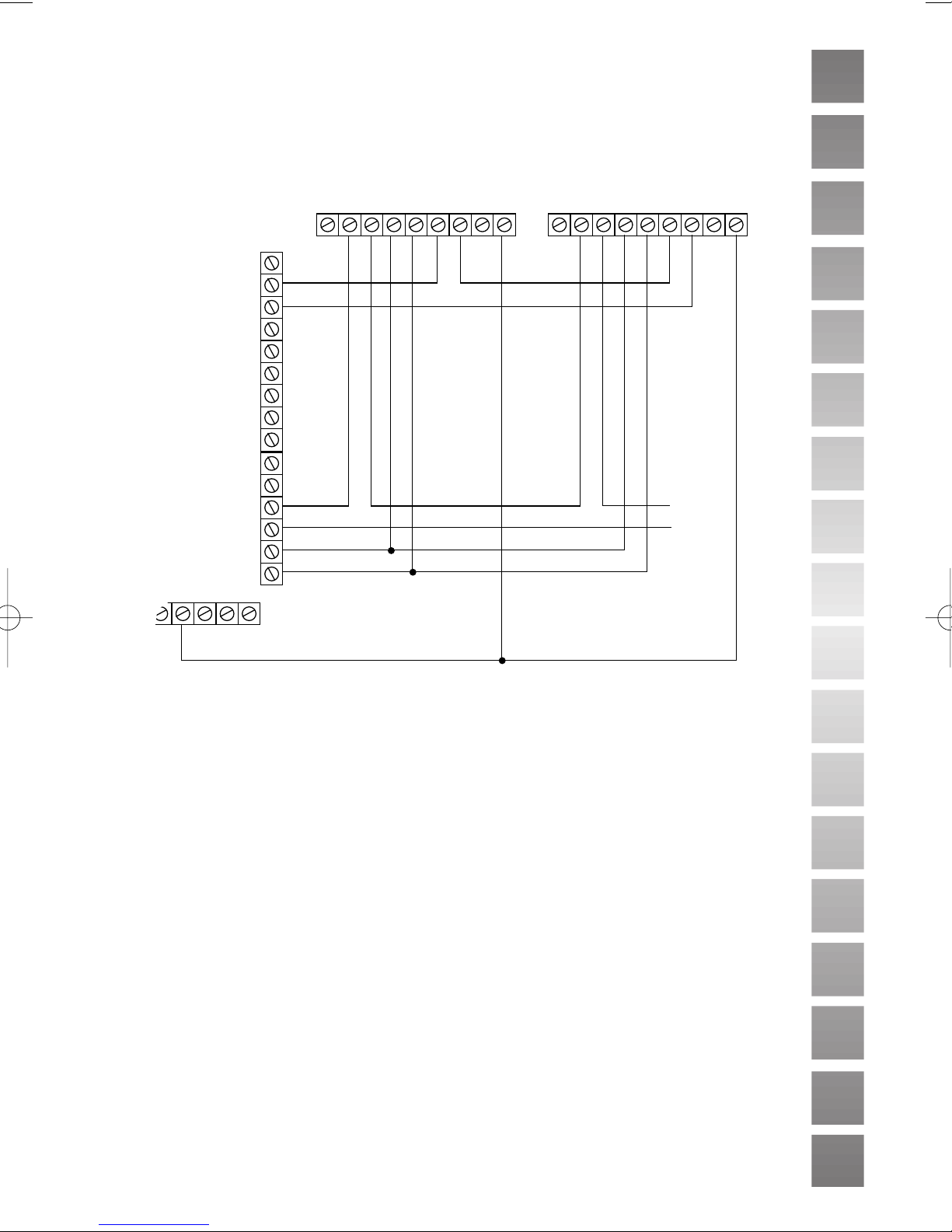
Connecting Detectors
Figure 8 shows the zone connector at the panel. Zones 1 and 2 share a com-
11
496219 Issue 1

mon terminal, as do zones 3 and 4, and zones 5 and 6. Make sure the tamper
Z1
Z2
Z3
Z4
Z5
Z6
KSF
KSP
A/T
A/T
12V
0V
AT AT + - AL AL T LTSP
PIR (330 SHOWN)
CONTROL PANEL
To other zone's
anti tamper
connections
} TO ZONE 1
} TO ZONE 2
} TO ZONE 3
} TO ZONE 4
Z1
Z2
Z3
Z4
Z5
Z6
A/T
KSF
KSP
12V
0V
AUX
ZONE 1 A/T
ZONE 6 A/T
circuit of each detector is connected in series to the A/T connections on the
zone connector.
Figure 8. Connecting Detectors
Connecting PIR Detectors
When fitting PIR detectors consult the installation instructions and technical
data supplied with the unit.
If you are fitting one detector per zone then the wiring is straightforward (see
Figure 9).
Installation
12
Figure 9. Connecting One Detector Per Zone.
496219 Issue 1
If you wish to connect more than one detector per zone then use the latch
AT AT + - AL AL T LTSP
PIR (330 SHOWN)
Z1
Z2
Z3
Z4
Z5
Z6
KSF
KSP
A/T
A/T
12V
0V
OP1
CONTROL PANEL
AT AT + - AL AL T LTSP
PIR (330 SHOWN)
To other
zone's
anti tamper
connections
facility so that the user can identify which unit has triggered. The panel uses
OP1 programmed as ‘set latch’ to keep the activity LED on the active PIR
glowing. You will need 8 core cable for this facility (see Figure 10).
Wiring Door Contacts
A door contact has two parts: a reed switch housed in a plastic casing, and a
magnet. There are two types of door contact suitable for domestic installation:
Surface and Flush. The Surface contact is fitted on the facing of the door
frame with the magnet fitted in-line on the door. The Flush contact is fitted
into the frame by inserting it into a pre-drilled hole. The magnet is flush and
aligned with the reed switch.
Figure 11 shows shows example connections for typical Surface contacts,
using 4 core cable to wire contacts in series.
Figure 10. Connecting Two PIRs in Series Using the Latch Facility.
Installation
13
496219 Issue 1

Fitting and Wiring Remote Keypads
To next keypad
if using daisy
chain wiring
I/P SIG 0 V +V
Normally open
push to make
exit terminate button
Stb Bell 12V 0V TR LS LS OP1 SIG ARM RDY
Note: 625 keypad is supplied
with the 602 panel.
Address
Link
Volume
Control
Sounder
Tamper
Switch
625 Keypad Circuit Board
CONTROL PANEL
Z1
Z2
A/T
A/T
12V
0V
Note: If only one
contact is fitted, wire
it as last contact.
Surface contact
Control panel
Figure 9 shows the connector inside of the 625 remote keypad.
Installation
Figure 11. Connecting Door Contacts.
1. Remove the front of the keypad from the back.
2. Fix the back box to a smooth surface at a convenient height for the user.
3 Connect wiring from the panel to the to the keypad connector.
4. Wire the second keypad, if fitted, in parallel to the first. Connect the
cable either at the first keypad (daisy chain) or at the panel (star). The
maximum cable length is 100m.
14
Figure 9. Connecting Remote Keypads
496219 Issue 1

5. Cut the address link in the second keypad to change its address.
Z5
Z6
A/T
KSF
KSP
12V
0V
AUX
PART FULL
UNSET
READY (GREEN)
ARMED (RED)
ARM RDY
Momentary or latched connection
Status LED connection
6. If fitting an Exit Terminate button connect a Normally Open button to
the terminals marked 0V and IP on the keypad.
7. Re-assemble the keypad, ensuring that the tamper switch is closed.
Connecting Keyswitches
Figure 10 below shows an example connection for a typical keyswitch, for
fixed or momentary operation.
Figure 10. Keyswitch Connections
See ‘Key Switch Operation’ on page 20 for the correct settings to use either
type of switch.
Installation
496219 Issue 1
15

Wiring External Sounder
BELL
+Hold Off
-Hold Off
-Ve Ring
Tamper Return
CONTROL PANEL
TYPICAL BELL MODULE
BELL OR SIREN (350 mA)
STROBE
-ve +ve
9040 16Ohm
SPEAKER
Stb Bell 12V 0V TR LS LS OP1 SIG ARM RDY
Figure 11 shows an example of connections for a typical external sounder (see
the manufacturers instructions supplied with individual units for further information on wiring diagrams)
Make connections to the control panel and SAB module as follows:
Installation
Strb Negative trigger in alarm for strobe light.
Bell Negative bell trigger (Programmable applied or removed)
12V Positive bell module hold off voltage (Supply).
0V Negative bell module hold off (Supply).
TR Negative tamper return from bell module to control panel.
Notes:
SAB shown for negative applied.
Link tamper return to 0V if no external tamper is required.
Connect all bell wiring to the control panel with the exception of the trigger to
the siren or bell. The bell/siren will continue to ring from the on-board battery
until the final connections are made after initial power-up. See ‘Initial Power
Up’.
Figure 11. Typical External Sounder Connections
16
496219 Issue 1

Fitting a Speech Communicator
6 5 4 3 2 1
Harness Plug
Locator
Note: Disconnect the speech communicator wiring harness from the main pcb
if you are NOT fitting a communicator.
Figure 12 shows the connector for the speech communicator.
Figure 12. Speech Communicator Connections
If required the 660 speech/digital communicator can be fitted inside the back
casing of the panel.
1. Locate the 660 toward the top of the back box, using the self adhesive
pads provided. Make sure the exposed part of the 660 is to the right.
2. Wire the communicator harness to the 660 as shown in the following
table:
Installation
601 Function Colour 660
Pin1 PA output - positive removed in alarm. Red ST2
Pin 2 Line monitor input, 12V positive applied for Line Fault. Blue LF
Pin 3 Burglar output - positive removed in alarm. Yellow ST3
Pin 4 Open/close output - positive removed in alarm Black ST4
Pin 5 12V Supply. Brown 12V
Pin 6 0V. Supply. Orange 0V
3. To connect the telephone line remove the 660 line connection cover and
connect a cable from the terminals provided to the telephone socket.
See the separate 660/960 Installation and Programming Guide for correct connections and further instructions.
4. Reassemble the 660.
DO NOT plug the speech communicator harness onto the panel’s main
circuit card at this point.
Telephone Line Fault
If a telephone line fault occurs while the system is unset, then the panel gives
an internal alarm. When the user keys in their access code, the panel flashes
the Tamper LED on and off every two seconds.The user can still arm the system with a telephone line fault present.
If a telephone line fault occurs while the system is armed, and an intruder
alarm occurs, then the panel overrides any programmed bell delay and triggers
the external sounder immediately.
17
496219 Issue 1

Programming
Initial Power Up
Before applying power to the panel make sure that:
• All used circuits are connected.
• The Bell trigger is NOT connected to the external sounder.
• The battery or speech communicator (if fitted) is NOT connected.
• The global anti tamper circuit is closed and the tamper return (TR)
is linked to 0V.
Note:The panel will not enter programming mode if the global anti tamper is
open circuit, or if the negative tamper return is not present.
1. Close the 601 (or 602) lid or defeat the lid tamper.
2. Apply mains power to the 601/602.
The Power LED comes on.
3. Key in the default user code (1234) if there is an alarm. Ignore any LEDs
that are lit at this stage.
4. For a 601:
Key in
0 + ENTER + the engineer code (default 7890).
The panel bleeps once per second.
Open panel lid or release the panel tamper.
The panel bleeps twice and all the LEDs flash.
You are now in Programming Mode.
Programming
5. For a 602 with 625 keypad:
Key in
0 + ENTER + the engineer code (default 7890).
The keypad bleeps once per second.
Open 602 end station lid or release the tamper.
The 602 bleeps twice if a 9040 sounder is fitted. (Keypad LED’s do not
flash.)
You are now in Programming Mode.
6. Connect the battery and make any final wired connections (for example
bell trigger to the external sounder, or communicator harness to main
pcb).
7. Remember to remove any link between 0V and TR if you are fitting a
SAB.
18
496219 Issue 1

Default Settings
When delivered from the factory, the panel is programmed as follows:
Zone 1, Entry/Exit, Chime, active in Part Set. 01 489
Zone 2, Entry Route, active in Part Set, Omit allowed. 02 39 OMIT
Zone 3, Normal Alarm, active in Part Set, Omit allowed. 03 19 OMIT
Zone 4, Normal Alarm, active in Part Set, Omit allowed. 04 19 OMIT
Zone 5, Normal Alarm, Omit allowed. 05 1 OMIT
Zone 6, Personal Attack. 06 5
Strobe output 11 49
Programmable output 1 is PIR Set Latch. 12 18
Engineer code is 7890. 20
Key switch operation is momentary. 21 0
PA gives audible alarm. 30 0
Customer reset. 31 0
2-Ply Entry Timer disabled. 32 0
Keypad PA enabled. 33 1
LEDs ON during Set. 34 1
Exit mode is Timed or Terminate. 35 0
Rearm after alarm three times. 40 3
External sounder delay zero (instant alarm). 41 0
External sounder duration three minutes. 42 2
Entry time is 20 seconds. 43 4
Exit time is 20 seconds. 44 4
Communicator outputs normal. 51 0
During Part set Entry/Exit zone starts entry timer. 60 0
During Part set Entry Route zone starts entry timer. 61 1
During Part set the exit mode is the same as full set. 62 0
Part set alarm response local only (no communications). 63 0
User 1 code 1234.
User 2 - 8 code 0001 to 0007 *
(inactive).
Duress code OMIT OMIT
OMIT OMIT
(inactive).
* The default code for user two is ‘0001’, for user 3 it is ‘0002’ and so on up
to user 8, which is ‘0007’. Refer to the 601 User Guide for instructions on
changing the user codes.
Programming
Programming Commands
To change the factory default program, use the commands listed in this section as follows:
1. Enter the command number.
2. Enter one or more digits to give the new program.
3. Press ENTER.
The panel will give a double bleep to show that it has accepted the command. If you enter the command incorrectly the panel gives a single
tone.
19
496219 Issue 1

To change Key in: Followed by: + ENTER
Zones 1-6 01-06 0= Not used
Example:
Select one zone type from
0 to 7.
Choose which attributes
you require from 8, 9 and
OMIT.
Then press ENTER.
Strobe Output 11 Reserved. Do Not Use
Programmable Output 1 12 18 = PIR Set Latch (+ve applied when
Example:
To select Shock Sensor
Reset key in 12 28 and
then press ENTER.
Engineer Access 20 Any 4 digit code
Key Switch Operation 21 0 = Momentary
Programming
PA 30 0 = Audible Alarm
System Reset 31 0 = Customer Reset
2-Ply Entry Timer 32 0 = Disabled
Keypad PA 33 0 = Disabled
Set/Part Set Display 34 0 = LEDs ON when set and part set
Exit Mode 35 0 = Timed or Terminated
Rearm 40 0 = Never
1= Normal Alarm
2 = 24 Hour Alarm
3 = Entry Route
4 = Entry/Exit
5 = PA
6 = Fire Alarm
7 = Technical Alarm
In addition:
8 = Chime
9 = Active in Part Set
OMIT = Omit Allowed
active)
19 = +ve removed when active. Not
normally used
28 = Shock Sensor Reset (+ve removed
when active)
29 = +ve applied when active. Not
normally used
3 = Reserved
48 = Not normally used
49 = Strobe (-ve switched)
58 = +ve removed when active. Not
normally used
59 = Internal Alarm (+ve applied when
active)
1 = Latched
1 = Silent Alarm
1 = Engineer Reset
1 = Enabled
1 = Enabled
1 = LEDs OFF when set and part set.
1 = Final Door Set
1 = Once
2 = Twice
3 = Three times
4 = Always
20
496219 Issue 1

To change Key in: Followed by: + ENTER
External sounder delay 41 0 = Nil
1 = 1.5 mins
2 = 3 mins
3 = 5 mins
4 = 10 mins
5 = 15 mins
6 = 20 mins
Ext. sounder duration 42 0 = Nil
1 = 1.5 mins
2 = 3 mins (default)
3 = 5 mins
4 = 10 mins
5 = 15 mins
6 = 20 mins
Entry Time 43 1 = 1s
2 = 10s
3 = 15s
4 = 20s
5 = 30s
6 = 60s
Exit Time 44 0 = Continuous
1 = 1s
2 = 10s
3 = 15s
4 = 20s
5 = 30s
6 = 60s
51 Reserved. Do Not Use
Part Set Entry/Exit 60 0 = Starts Entry Timer
1 = Instant Alarm
Part Set Entry Route Zone 61 0 = As Entry Route
Response 1 = Start Entry Timer
Part Set Exit Mode 62 0 = As Full Set
1 = Silent Set
2 = Instant Set
Part Set Alarm Response 63 0 = Local (No comms)
1 = Full
Programming
Restoring Factory Default Settings (Command 98)
If you want to restore all the programming to the original factory defaults,
then:
2. Key in 98 + ENTER.
The panel erases all programming the user or previous engineers have entered,
and restores the original factory defaults.
Leaving Programming Mode (Command 99)
1. Close panel lid.
2. Key in 99 ENTER.
The panel bleeps twice and the Power LED glow steadily. The panel is
now in user mode.
21
496219 Issue 1

To Re-enter Programming Mode
1. Key in 0 + ENTER + (engineer access code)
The panel starts bleeping once per second.
2. Open the panel lid.
The panel bleeps twice and all the LEDs flash. The panel is now in program-
ming mode.
Restoring Default Engineer and User Codes
If you want to remove any programmed Engineer and User codes (perhaps to
reuse the panel with another user) then:
1. Remove Mains supply.
2. Open 601/602 lid and remove Battery supply.
Note: Leave the lid open and make sure the Lid Tamper switch does not
close, or this procedure will not work.
3. On the 601: hold down OMIT and 9 and reconnect battery supply.
4. On the 602:short together the two RST pins on the main pcb with a
small screwdriver and reconnect battery supply. Remove the screwdriver
after three seconds.
5. Close lid and key in 1234.
Programming
22
496219 Issue 1

Testing
Once the panel is installed, connected and programmed, there are several programming commands that can be used to test it while in Programming Mode.
These are listed below (Press ENTER to stop any test.):
To Test Key in: Followed by:
Engineer Log 90 4 see earlier events.
5 to see more recent events.
ENTER to quit log. (15 events max.)
External Sounder 91 ENTER to stop test.
Strobe 92 ENTER to stop test.
Internal Sounder 93 ENTER to stop test.
Output 1 95 ENTER to stop test.
Walk Test 97 ENTER to stop test.
Testing
23
496219 Issue 1

Fault Finding Guide
Symptom Response
• POWER LED FLASHES CONTINUOUSLY.
• SAB WILL NOT STOP RINGING.
• ALARM ACTIVATED, TAMPER LIGHT
FLASHING RAPIDLY AFTER USER CODE
ENTERED.
ES EVERY TWO SECONDS.
• AFTER ENTERING ENGINEER CODE THE
SOUNDER BLEEPS EVERY SECOND, BUT
WHEN LID TAMPER OPENED SYSTEM WILL
NOT ENTER INTO PROGRAMMING MODE.
• Mains supply has failed, panel operating from
battery only.
• Check mains connection and fuse.
• SAB not receiving power.
• Check 12V supply present.
• Check tamper switch on external sounder.
Ensure cover on external sounder is secure.
• Check negative tamper return present.
• Check global anti tamper is closed circuit.
• Check lid tamper is properly closed.
• Check for telephone line failure.• ALARM ACTIVATED, TAMPER LIGHT PULS-
• Check that the global anti tamper terminals
are closed circuit.
• Check the negative tamper return is present.
• If lid tamper is already open, close and open it
again.
Fault Finding
24
496219 Issue 1

MANUFACTURED IN THE UK BY SCANTRONIC LTD.
(CALLS CHARGED AT 39P PER MINUTE CHEAP RATE,
PRODUCT SUPPORT (UK) - TEL - (0891) 616343
BETWEEN 09:00 AND 17:30, MONDAY TO FRIDAY.
49P PER MINUTE AT ANY OTHER TIME.)
PRODUCT SUPPORT FAX NO. (01594) 544136.
Part No. 496219 Issue 1
 Loading...