

Page 1
Industrivej 3-9
DK-9460 Brovst
Denmark
Tel.: +45 98 23 60 88
Fax.: +45 98 23 61 44
Manual
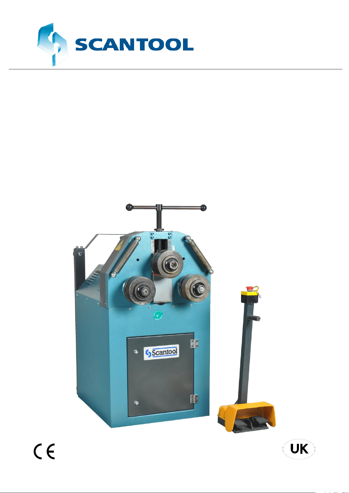
SCANTOOL
Profile bending machine
PV 35
Page 2

2
EU declaration of conformity
hereby declares that
SCANTOOL Profile bending machine PV 35
are manufactured in accordance with the provisions of the European Parliament and
Council Directive 2006/42 / EC of 17 May 2006
And also in accordance with:
• Low Voltage
• EUROPEAN PARLIAMENT AND COUNCIL DIRECTIVE 2014/35 / EU of
26 February 2014
• EMC
• EUROPEAN PARLIAMENT AND COUNCIL DIRECTIVE 2014/30 / EU of
26 February 2014
SCANTOOL A/S
Industrivej 3-9
9460 Brovst
Denmark
Website: www.scantool-group.com
Tlf: +45 98 23 60 88
Fax: +45 98 23 61 44
Page 3

3
Table of Content
1.0 GENERAL NOTES ........................................................................................................ 4
Introduction ..................................................................................................................................... 4
Transport ......................................................................................................................................... 5
Electrical lnformation ..................................................................................................................... 5
Maintenance .................................................................................................................................... 5
Safety .............................................................................................................................................. 5
2.0 GENERAL SAFETY TERMS ......................................................................................... 6
Machine's Safety Accessories and Accident Prevention Terms ...................................................... 6
Abnormal Conditions ...................................................................................................................... 6
Transporting, Lifting and Carrying. ................................................................................................ 6
3.0 PV 35 TECHNICAL PROPERTIES ................................................................................ 8
4.0 CAPACITY CHART FOR PV 35 .................................................................................... 9
5.0 STANDARD ROLLER DIMENSIONERS FOR PV-35 ................................................. 10
6.0 FOUNDATION AND MAIN DIMENSIONS OF PV 35 .................................................. 11
7.0 OPERATING PV 35 HORIZONTAL ............................................................................. 13
8.0 START-UP INSTRUCTIONS ....................................................................................... 14
9.0 OPERATION ................................................................................................................ 16
Operating instructions ................................................................................................................... 16
Operational hints ........................................................................................................................... 18
10.0 MAINTENANCE ........................................................................................................... 19
11.0 LUBRICATION............................................................................................................. 20
Lubricate chart ....................................................................... 20
Part List ......................................................................................................................................... 21
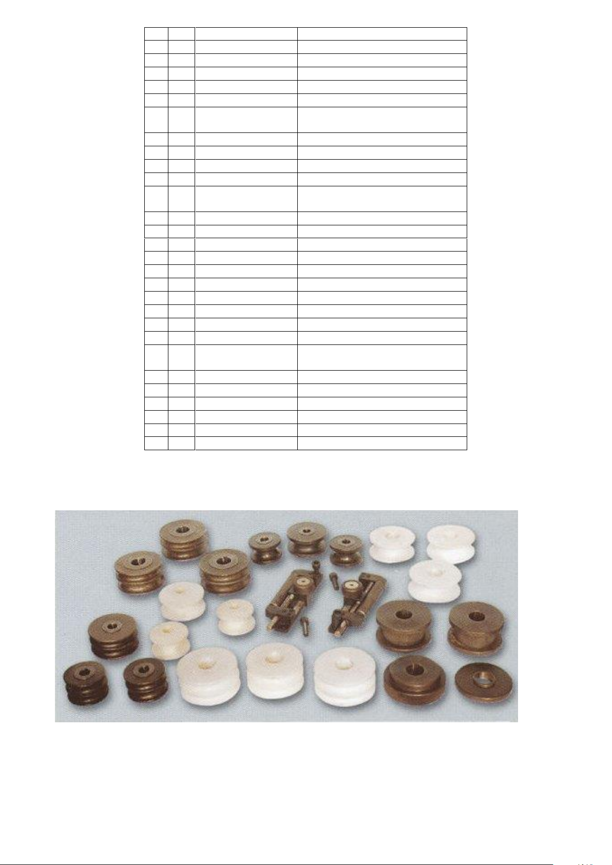
12.0 SPECIAL ACCESSORIES FOR MODEL PV 35 ......................................................... 22
Various special rolls: ..................................................................................................................... 22
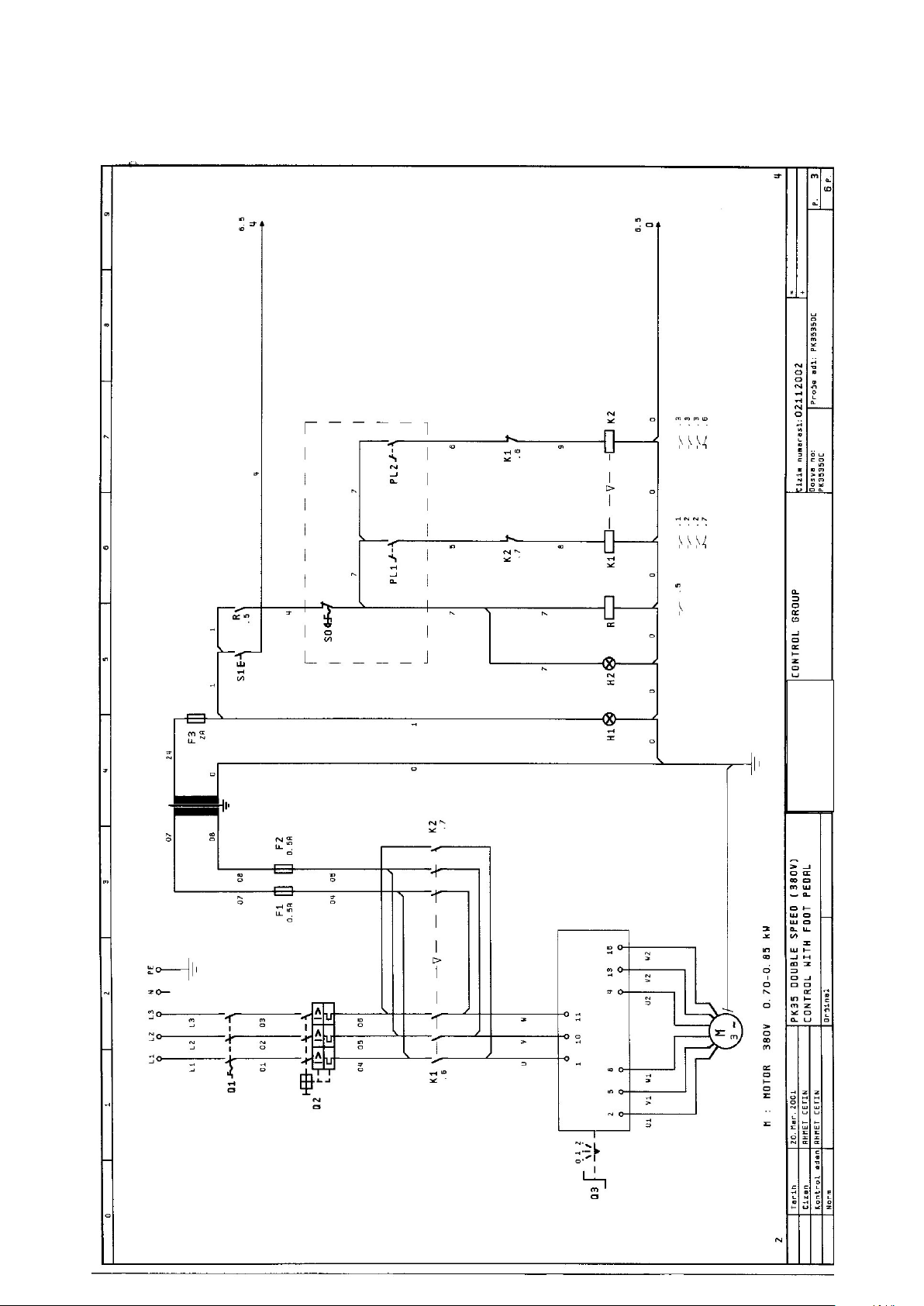
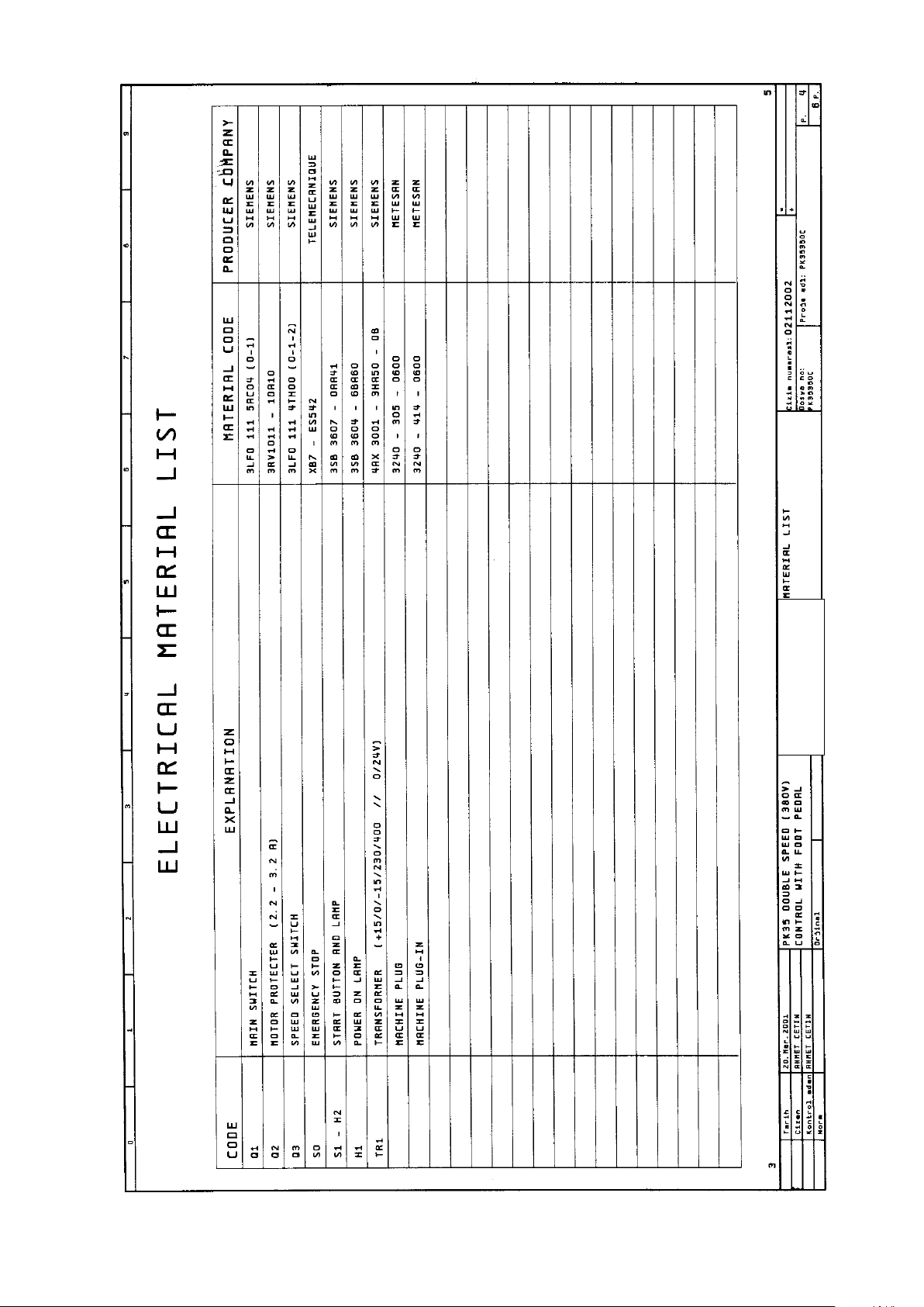
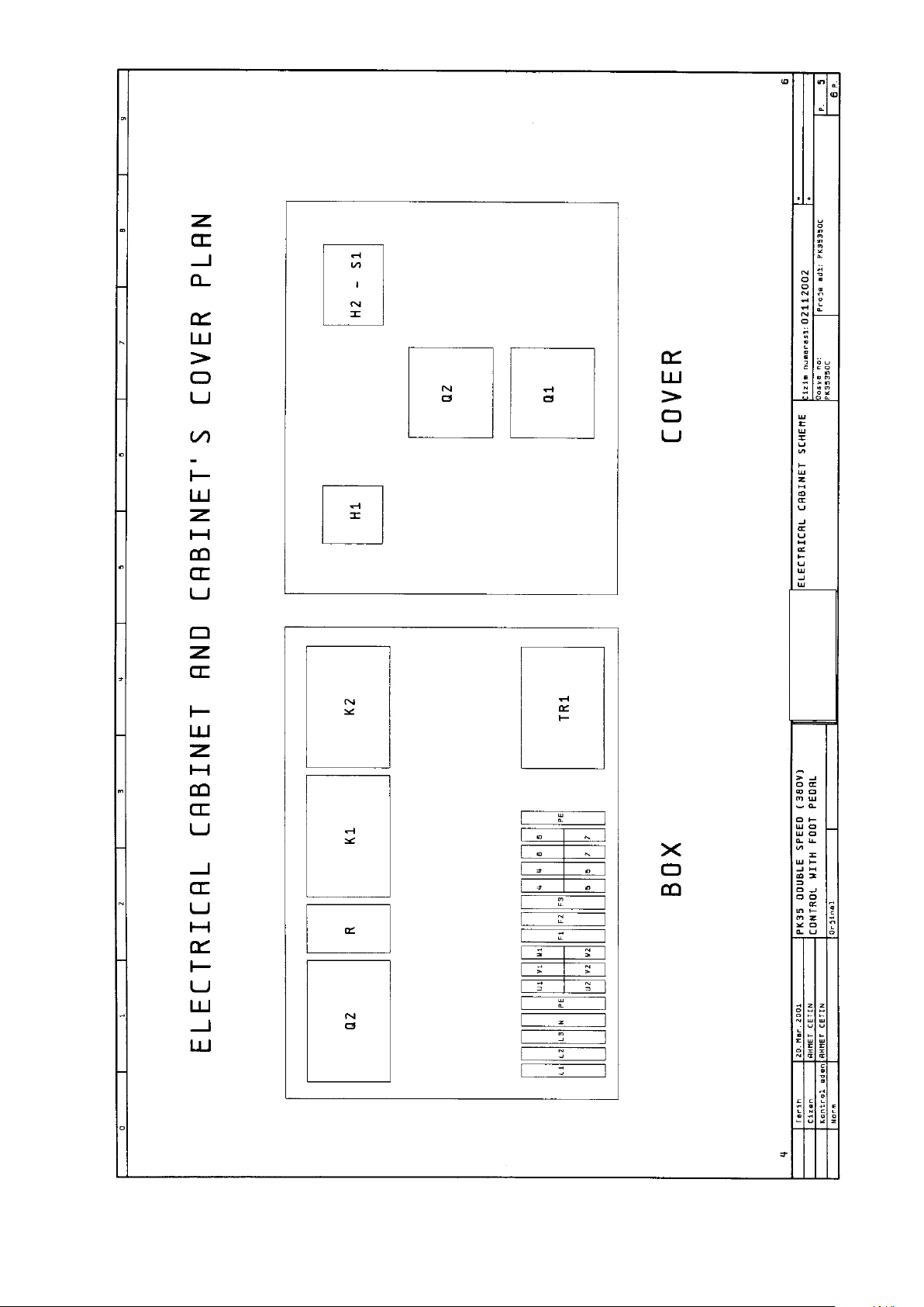
13.0 ELECTRIC DIAGRAM ................................................................................................. 23
Warranty ................................................................................................................................ 26
Guarantee ...................................................................................................................................... 26
Page 4

4
1.0 GENERAL NOTES
Introduction
This User's Manual is absolutely for your safety and is essential for the machine to have a long
production life. As long as you keep up with our Manual you will be able to run your machine smoothly
and safely. Keep in mind that the machine is designed absolute/y to perform maximum safety and for
efficient working.
In this Manual you can find instructions and information about:
Correct installations of the machine
Description of the functional parts of the machine
Set-up and start up adjustments
Correct standard and scheduled maintenance
Simple safety regulations and accident prevention.
Therefore, as far as the user's safety is concerned, in this handbook the possible risks connected with
machine operation are pointed out as follows:
ATTENTION: Showing the risks of accident, if instructions are not followed.
WARNING: Showing the probable damages to the machine or equipment, if the instructions are not
strictly followed.
NOTE: It gives useful information.
It is certainly necessary that the operator should read and understand all the ATTENTION WARNING
notes specified in this Manual before starting with operation of the machine and before any lubrication
or maintenance intervention.
On all steps of installation, operation and maintenance safety must be your first concern for the
protection of yourself, other users and the service of the machine.
In case of any failure please first refer to this Manual, and then if a solution cannot be found contact
first of all the distributor where you purchased our product. Do not forget to refer to the drawings and
the numbers for any spare part needed or to define any problem. Make sure you have the serial
number and production year of the machine.
Our technical staff will make their best to help you in the most convenient way.
Page 5

5
Transport
As soon as you receive the machine, check for any visible transport damages. Remove any protective
crates around the machine and read the instructions on related chapters of this Manual carefully to set
up the machine. If the machine is damaged while transport, immediately take some photographs
for insurance claims.
Take precautions while loading / unloading or moving the machine to avoid any injuries. Refer also to
related chapter of this Manual for the best way of handling the machine.
Electrical lnformation
All necessary connection procedure can be found on this Manual. Do not try to connect the machine
before reading these procedures and fully understanding the drawings. Have the machine connected
by a qualified electric technician. For, as we made clear in the “general conditions of guarantee”,
under no circumstances installing mistakes, one of which is the electrical connection mistake, can be
covered in the guarantee agreement. Always turn off power before making any connections or
disconnecting the machine.
Maintenance
Your machine is designed and produced to work efficiently and smoothly. To achieve this you should
also take care while operating the machine. Regard Maintenance sections to have the longest life
from your machine. Try and use original span3 parts where necessary and most importantly do not
overload the machine or do not make any unauthorized modifications.
Safety
Take all precautions possible to avoid any personal injury while using the machine. Keep in mind to
protect the third party people around the machine. Refer to safety instructions.
Page 6

6
2.0 GENERAL SAFETY TERMS
Machine's Safety Accessories and Accident Prevention Terms
The machine is provided with fixed shelters for the protection of all gears. But some mobile parts,
because of their shape for the bending processing cannot be protected within a case. However, safety
is guaranteed by the machine features and by the use of "human presence" controls.
The machine is controlled by means of foot-pushed buttons present at the downside of the Mobile
Control Panel. During operation the specified safety distance must always be observed.
There is a red mushroom emergency button at the upside of the Mobile Control Panel to stop all the
machine activity by disabling the electric supply until released. In case of an extraordinary situation,
please push this button straight away.
No other persons except for the qualified and well trained operator should be allowed to use the
machine and to be present in the working area of the machine.
Any damaged or defective connections to the different energy supplies must be replaced.
All interventions concerning installation, start-up, change of equipment, use, change to the use and
the operation, regular maintenance, inspection and periodical maintenance can be performed only
after disabling the machine according to relevant chapter of this handbook.
Abnormal Conditions
In order to avoid unusual working conditions, in the following several recommendations to the operator
are listed. Also, do not forget that this machine can be used only in the conditions presented in this
operation and maintenance handbook
Before connecting the machine double-check electrical connections read the instructions carefully.
For, almost 65% of the failure reports we receive are based on either wrong electric connection or use
in contradiction to the User's Manual
Avoid the approach of persons to the operator while the machine is running.
Loading and unloading of the material should be done according to the instructions of this handbook.
During the bending process avoid holding material with the hand.
Never wear garments with Ioose parts, which may be dragged by the machine parts, long loose hair,
necklaces, rings etc.
Never use goods except for the allowed ones as operational materials.
Never run the machine without safety devices.
Don't climb on the machine.
The machine cannot be installed and used in corrosive environments.
The machine must always be operated with one qualified operator who has the required knowledge to
use this machine properly.
Transporting, Lifting and Carrying.
Page 7
7
Before preparing the machine for installation and start-up, an accurate visual control is
required in order to detect any possible damages occurred during transporting and handling
phases.
Your machine is located on a wooden grid and the
package is a waterproof plastic cover.
If one, or several parts of the machine, have been
damaged while shipping, the installation of the machine
has to be suspended.
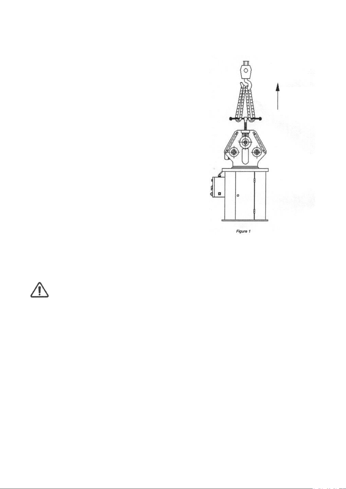
While lifting take care of these points:
• Always lift and carry the machine from the handles.
• Use a steel rope capable of carrying 500 kg.
• Do not forget the Mobil Control Panel.
• Take precautions for handling and lifting.
• Check if the load is properly balanced by lifting it
some centimetres.
• Lift the machine, proceeding with care, without
sudden accelerations or quick changes of directions.
• Place the machine where it must be installed, lower
the machine slowly till it touches the floor.
Figure 1 shows a way of carrying the machine. You can
use a crane with hook or a forklift for handling operation.
Figure 1
Attention: Lifting and carrying operations should be carried out by skilled workers,
such as truck operator, crane operator, etc. Also, it is necessary to keep in mind that
having large safety margins will provide you efficient working conditions and enable you
to take into consideration most of the precautions.
P = 400 Kg.
Page 8
8
3.0 PV 35 TECHNICAL PROPERTIES
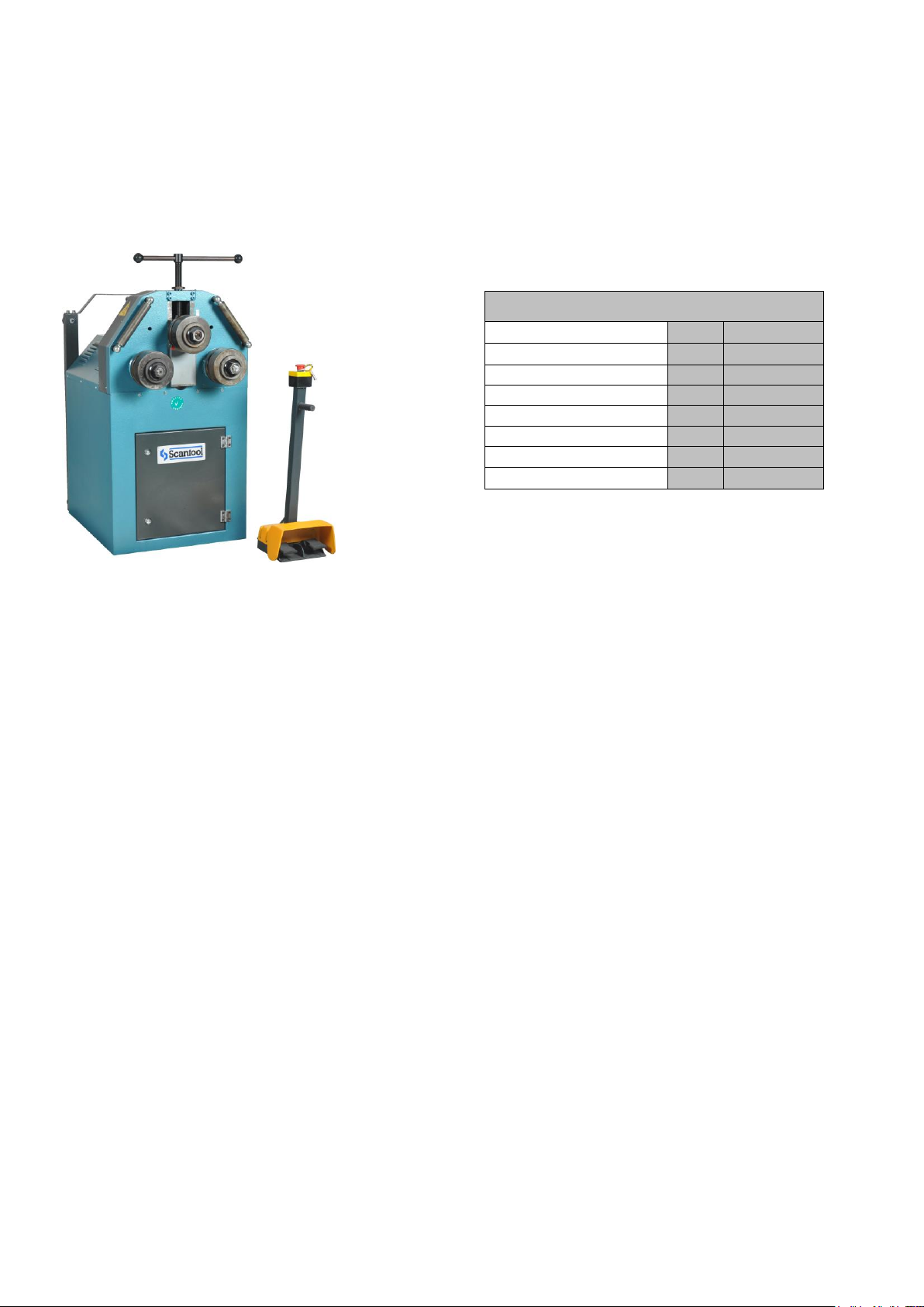
As a superior model in its own class the PV 35 is equipped with a powerful double speed motor and a
low noise reduction gearbox, which gives the machine power to bend with ease. The digital Read Out
(optional) that can be fitted to top roll gives higher accuracy and helps increase the efficiency. By
using Mobile Control Panel that includes foot pedal and an emergency stop you can easily and safely
bend the required materials. General Technical Information of PV 35 is given below.
STANDART SPECIFICATIONS SAFETY UNITS
Steel Frame Emergency Button on Mobile
Two rollers are powered Control Panel
Rolls are hardened Various DANGER signs around the
Rolls Shafts are Special Steel material machine.
hardened and grinded Brake motor (Optional)
Standard Rolls Overload Circuit - Breaker
Foot Pedal control
Guide Rolls
Horizontal and Vertical Working Position
User’s manual book
SPECIAL FEATURES
Pipe / Tube Bending Rolls
Profile Bending Rolls
Angle Bending Rolls
Digital Read Out
Special Lateral Angle Guides.
Double-Speed Motor
Note: Due to various safety regulations, the specifications presented here can change from couniry to
country without prior notice. Above dimensions and other characteristics can also change without prior
notice due to our constant improvements on our products.
MODEL: PV 35
Shaft Diameters
mm
50
Roll Diameters
mm
155
Working Speed
M/min
4,5
Motor Power
kW
1,5
Weight
kg.
400
Length
mm
1000
Width
mm
750
Height
mm
1400
Page 9
9
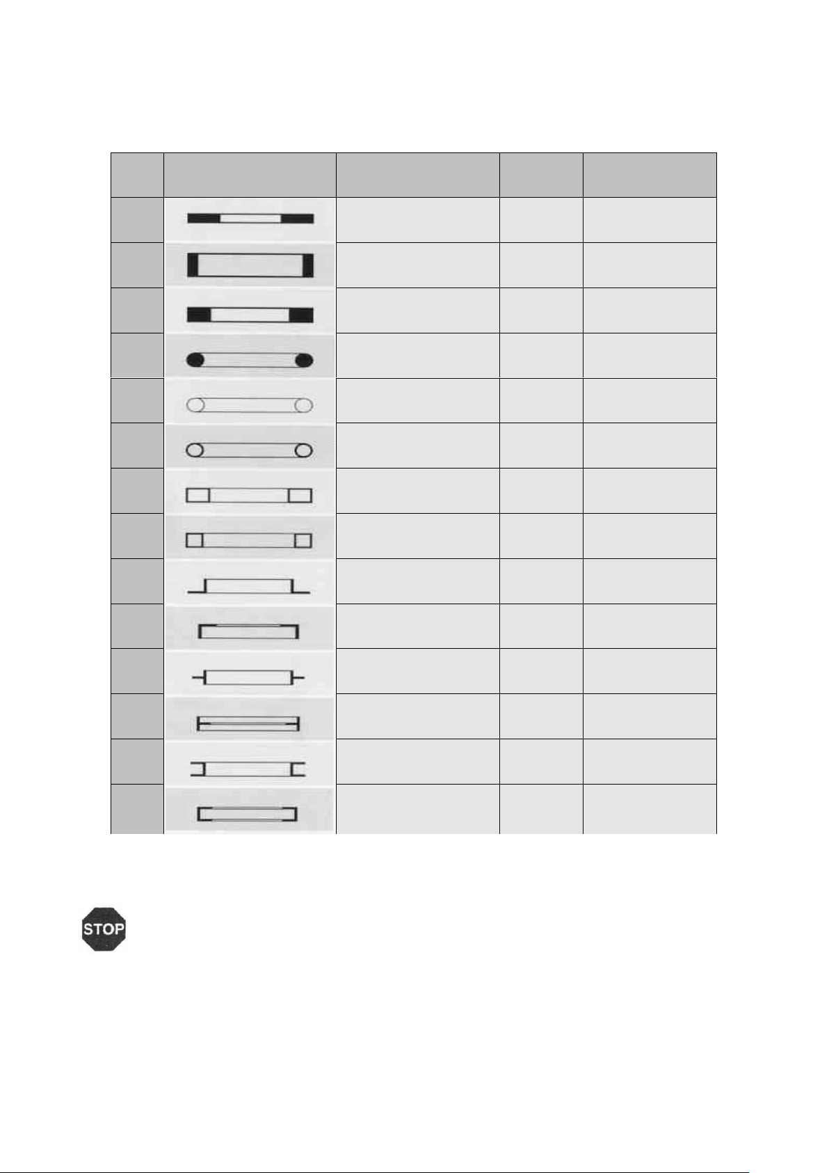
4.0 CAPACITY CHART FOR PV 35
WARNING: Do not feed profiles having a higher thickness than specified for the capacity
of the machine.
Do not feed more than one piece at a time.
Do not use the machine for any other scope the one for which it has been designed.
no
profile type
Maximum size
min. int
notes
1
40 x 10
60 x 10
500
800
Standard rolls
2
60 x 10
100 x 15
600
750
Standard rolls
3
20
35
400
1200
Standard rolls
4
30
35
600
800
Optional rolls
5
30 x 2
70 x 2
500
1200
Optional rolls
6
33.7 x 2.65
60.3 x 2.9 (2")
350
1200
Optional rolls
7
50 x 40 x 3
70 x 30 x 2
1500
1500
Optional rolls
8
40 x 40 x 3
50 x 50 x 3
800
2000
Optional rolls
9
50 x 50 x 5
60 x 60 x 6
850
1200
Optional rolls
10
30 x 30 x 3
50 x 50 x 6
700
1200
Optional rolls
11
50 x 50 x 6
60 x 60 x 7
650
900
Standard rolls
12
50 x 50 x 6
60 x 60 x 7
650
900
Standard rolls
13
UPN 60
UPN 80
550
1000
Standard rolls
14
UPN 30
UPN 80
800
1200
Standard rolls
Capacities are given for ST 42 materials.
We reserve the right to make changes without notices.
Page 10
10
5.0 STANDARD ROLLER DIMENSIONERS FOR PV-35
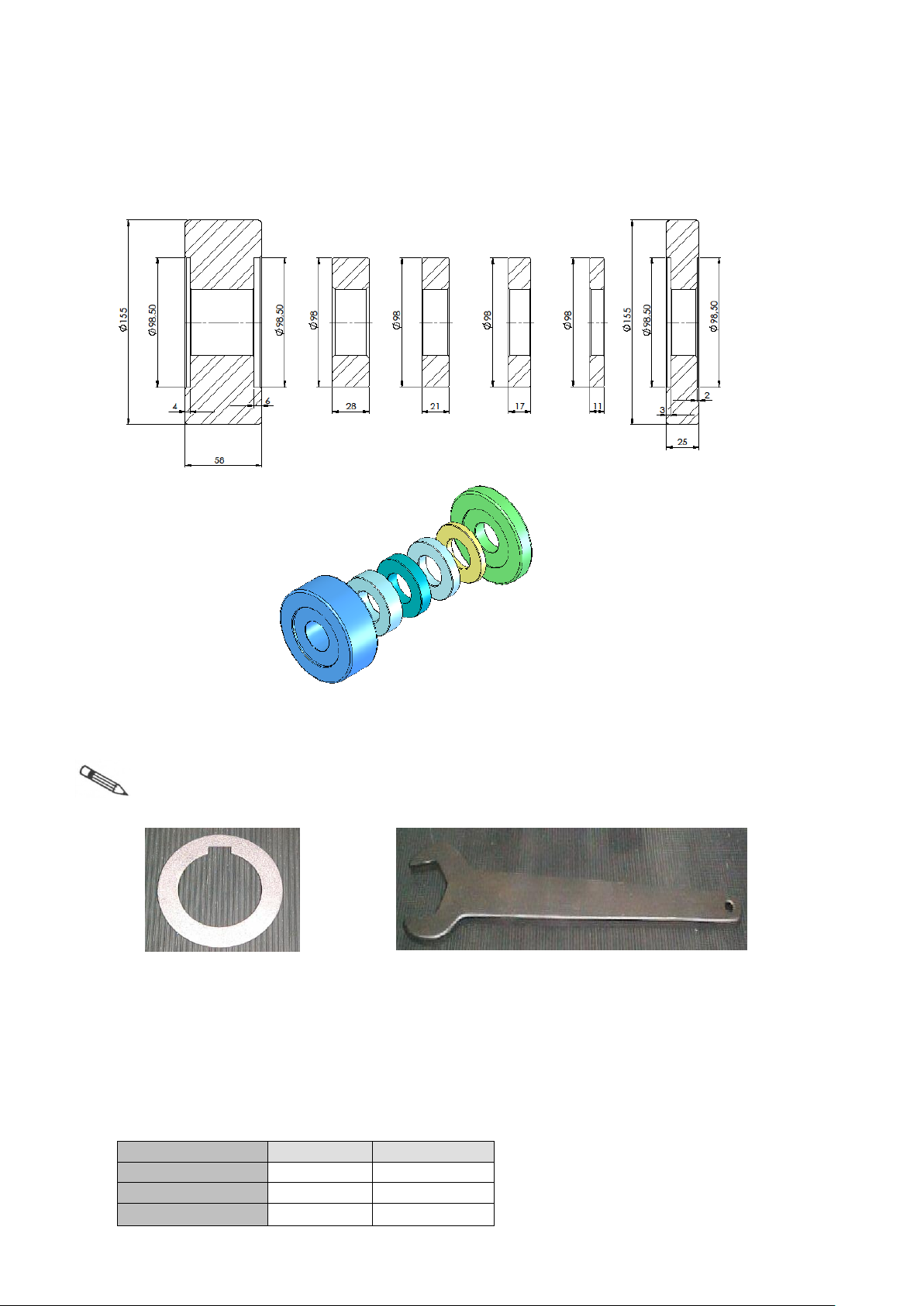
Note: As the three rollers have the same and standard sizes, the dimensions given in figure
1 is valid for them all.
Figure 2 Figure 3
We supply 6 pieces of spacers with the machine (as shown in Figure 2). These spacers can be
used to obtain different width with the standard set of rolls. The spacers are divided into two groups as
shown below.
This table is standard sequins of dimensions.
dimension
unit
group 1
diameter
mm
98
width
mm
28
piece 3
Page 11
11
6.0 FOUNDATION AND MAIN DIMENSIONS OF PV 35
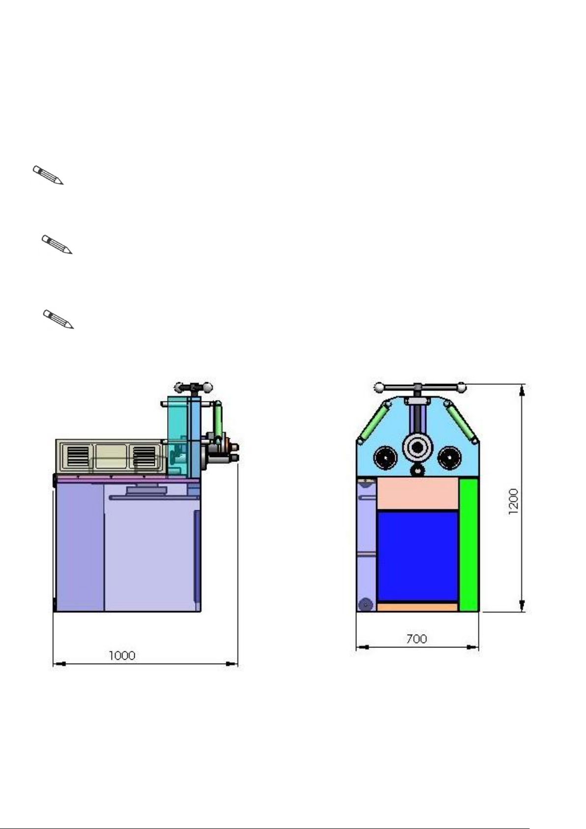
Figure 1 shows the main dimensions of the machine.
Note: For a correct operation the machine must be placed on a flat, preferably concrete
base and even floor.
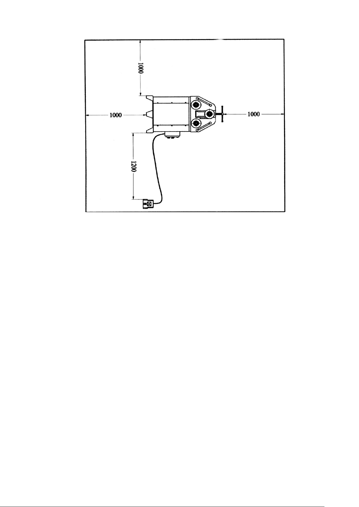
Note: Figure 2 shows the area into which anyone except for the operator is forbidden to
enter. that this area is illustrated considering the machine located horizontally. If you operate
it vertically, then the borders will be the same. That is, no matter how you located the
machine (vertical or horizontal) you should always keep the safety distance of one meter
around the machine.
Note: The manufacturer doesn’t accept any responsibility for damages due to the non-
observance of the above specifications.
Figure 1
Page 12
12
Safety Area (Figure 2)
Page 13
13
7.0 OPERATING PV 35 HORIZONTAL
Before positioning the machine it is necessary to leave enough working area for the proper
bending operations such as: extraction of the cylindrical profile, feeding of the semi product,
bending of big diameters.
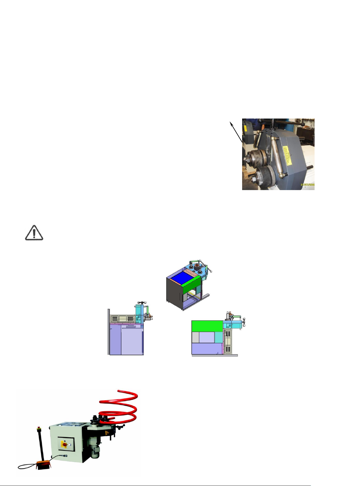
If you have no alternative to install the machine in a broad area but a low-height area, then
there is a solution to this problem as shown in figure 2.
To set the machine horizontally, follow these steps:
Wrap a belt capable of carrying at least 500 kg around the top roll’s
shaft (shown by in fig.1).
• Lift the machine slowly by means of a forklift or a crane with hook.
• When you are satisfied that you have lifted the machine to the
degree that only the corner shown by in figure 2 touches to the
floor, rotate the machine right slowly with the help of a person so that
the mass center of the machine tend to be at the right side of that
corner.
• After that, slowly lower the machine.
Attention:
Do not wrap the belt around the top roll adjustment screw so that it may be bent or its teeth
may be damaged.
Figure 2
Figure 3 shows an example of horizontal working.
Figure 3
Page 14
14
8.0 START-UP INSTRUCTIONS
1. Materials and Products
The machine is mainly steel and it is not designed for handling inflammable or detrimental products. It
is duty of the customer to check if the processed materials respond to these requirements. Also, it is
duty of the customer to check if the processed materials can be dangerous for the operator working
nearby.
When selecting the most appropriate operation material you should keep in mind those instructions:
• Material must be clean out of oil and dry.
• Hardness value must always be same thorough the material.
So, we recommend you to buy certificated steel.
• Parts to be bended should have smooth surface to fulfill the procession correctly and easily.
Note: The thorough cleaning of the rolls is absolutely necessary in order to avoid possible
sliding of the profile due to grease residues on the rolls.
2. Electrical Connection
Have a qualified electrician connect the machine to the electric supply. In some cases inverse
electrical connection causes the motor burn out. To avoid such an undesirable event, after having
connect the machine see that the motor turns to the direction shown by arrow when activated. Or you
can check to see if the rolls are rotating to the same direction of the pedals. That is, if the right pedal
is pushed, the rolls should rotate right and if the left pedal is pushed, the rolls should rotate left. If the
machine does not comply, then inverse the electric cables.
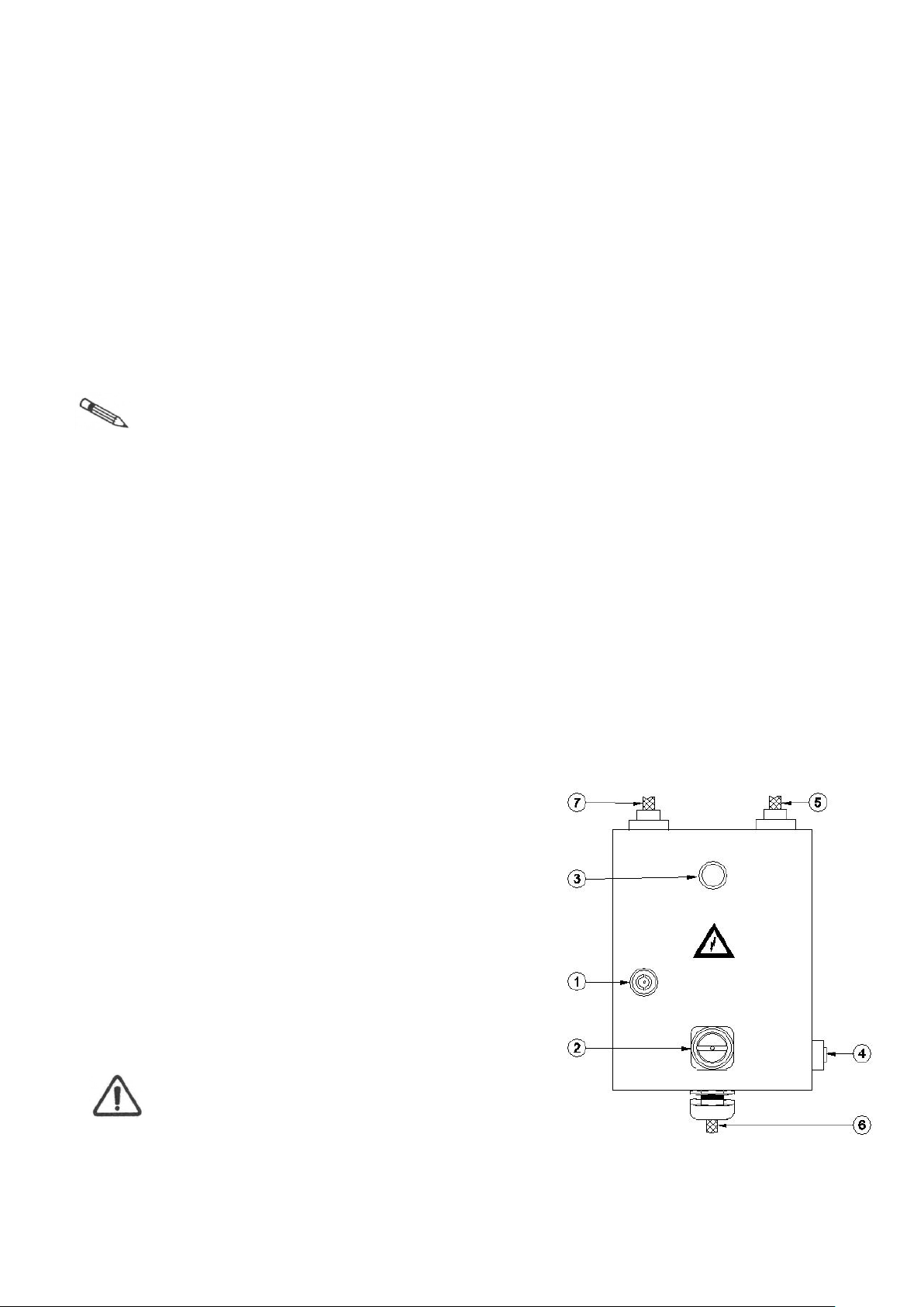
3. Electric Box
The PV 35s electric box includes very important controls of the machine and is also connected to the
below shown foot pedals. The keys on the electric box are shown and explained here:
1. Electric box lock
2. Main switch
3. Electric on indicator
4. Foot pedal plug-in
5. R-S-T phases plug-in
6. Electric plug-in
7. Digital connection (optional)
Attention: Electric box shelter must be removed
only when the machine is stopped, or during
maintenance or adjustment interventions.
Page 15
15
Warning: It is suggested to protect the main electric line from possible overloads by means of
safety switches.
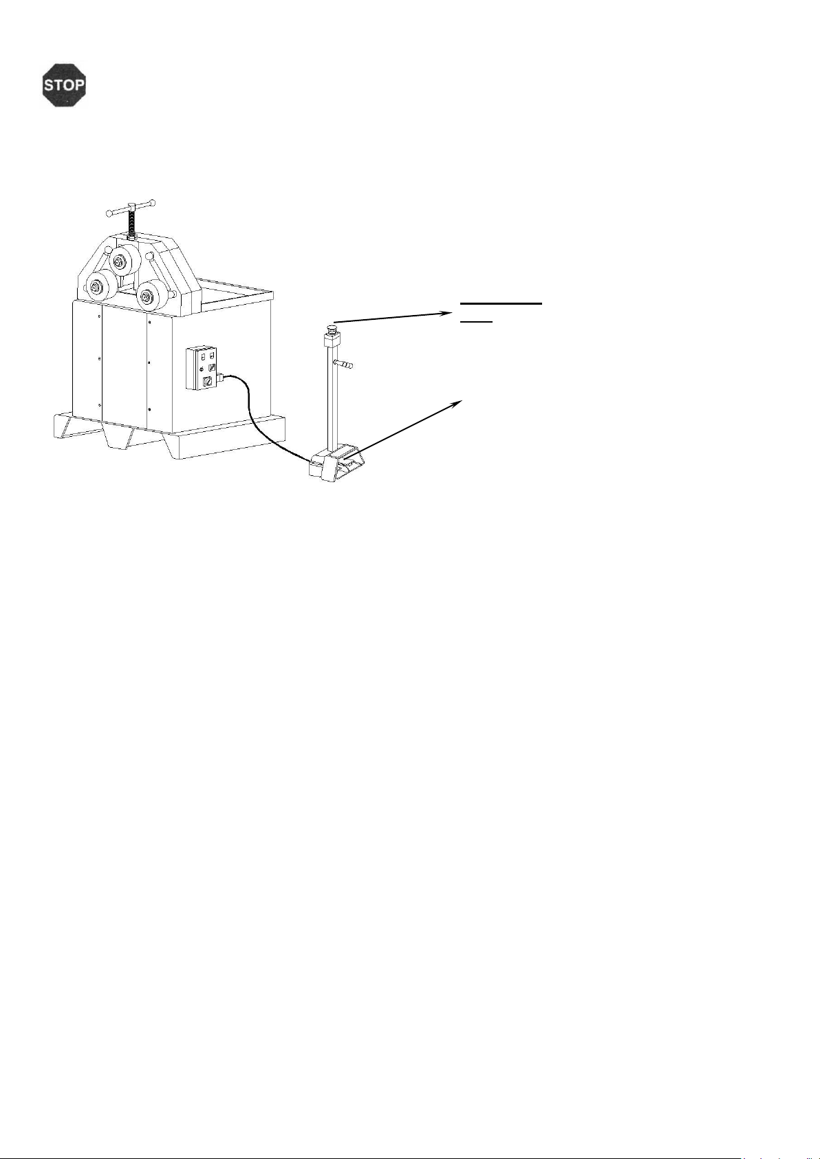
4. Foot Pedal
The foot pedal is equipped with an “emergency
button” which instantly stops all the machine activity
by disabling the electric supply until released.
5. Starting the Machine
Following steps will help you start the machine and get ready for the first bending operation. See the
sections identifying the necessary switches and buttons.
• Make sure the electrical connection is correct
• Turn on the “main switch”
• You will see electric on “indicator”
• Push “start button”
• Choose a speed from the “speed selector”
• Use the “foot pedals” to rotate the rolls
• Make bending
• Use the “emergency button” on “foot pedal” to stop the machine
• Turn off the “main switch”
6. Basic Operation Terms
The PV 35 has two rolls powered and top roll idle. The lower rolls are direct driven by a reducer motor.
Top roll can be adjusted by a screw driven system to make the bending in a wide radius range.
Therefore, bending operation is simple and smooth however requires experience for efficient working.
Following recommendations will be helpful during operation:
• It is recommended that the user have basic bending information with this kind of machines.
• Making a tight bend in one pass is not possible. So you need several passes before you can
achieve a certain radius. Tighter curves and full radii always take a lot of time.
• During operation never wear garments with loose parts, which may be dragged by the machine
parts, long loose hair, necklaces, rings etc.
• Use emergency button in case of any emergency.
Figure 2
Emergency
stop
Foot
Page 16
16
9.0 OPERATION
Operating instructions
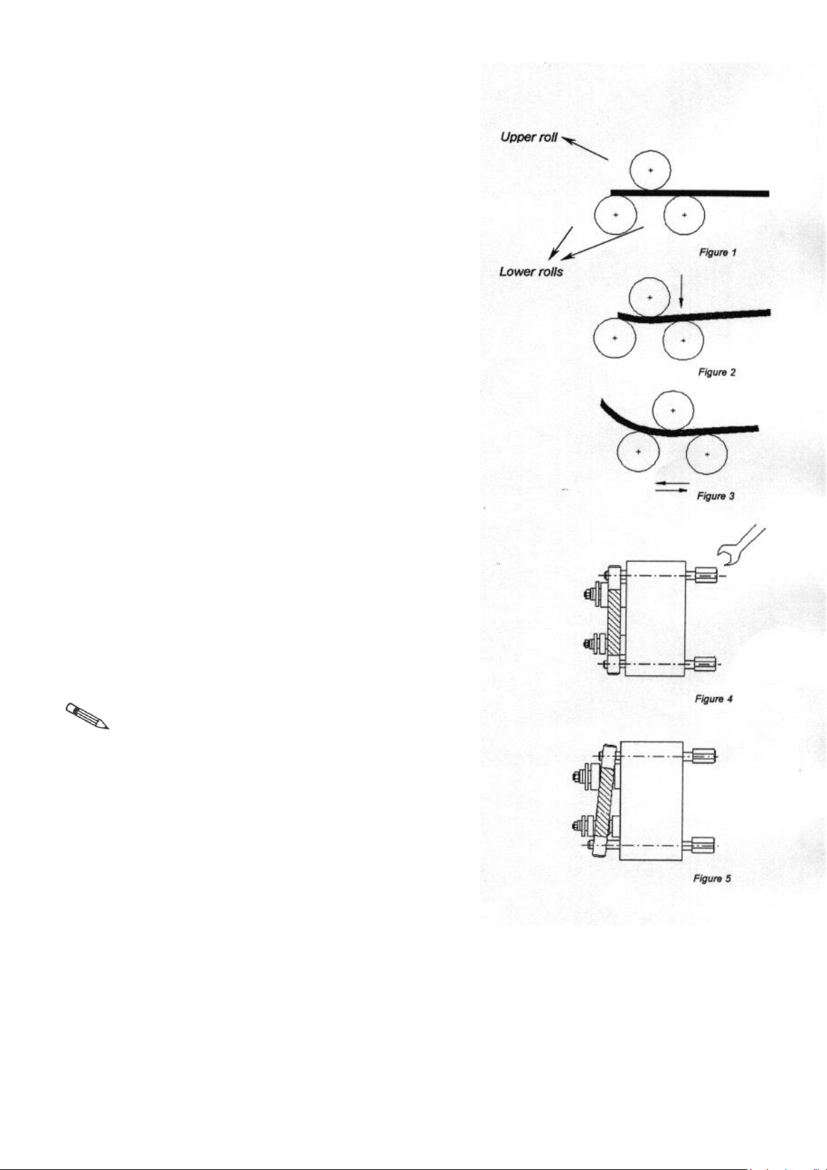
Place the material on the rolls flatly as shown in the figure 1.
Make sure that material is placed parallel to the ground and
touching all three rolls at the same time. This position is
called "zero position'.
Move the upper roll down like in figure 2 and position it to
apply enough force to bend the material. Do not apply force
more than necessary. If you apply too much force with the
help of moving the upper roll down a lot more than enough,
you may deflate the material during bending operation.
Push the foot pedal to rotate the rolls to which direction you
want (look at figure 3). To get desired diameter value make
more than one pass by gradually lowering the upper roll
after each pass. After a pass if the diameter value is bigger
than expected, move the upper roll down to apply more
force. If the case is vice versa, than move the upper roll to
upside by making use of milimetric ruler.
It is likely that the material will intend to bend right or left
because of the existence of bending forces. To prevent this,
you must adjust the guide rolls as shown in the figures 4 and
5.
As the guides are adjustable on top and bottom, you can
arrange them to the opposite side of the material's
directional inclination.
Note: To get a circular profile, side guide joints
must be parallel to the machine surface.
Otherwise, you just get spiral profiles.
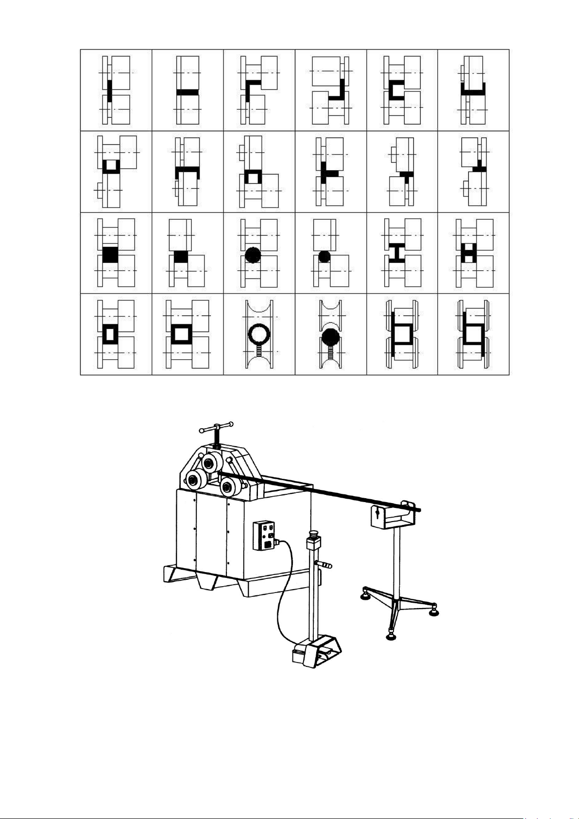
Figure 6 shows bending operations for different
kind of sections with special rolls.
In case of bending long materials, material
feeder is advised to use in order to keep
workpiece parallel to the base ground (see
figure 7). This will make easier to bend such
workpieces.
Page 17
17
Figure 6
Figure 7
Page 18
18
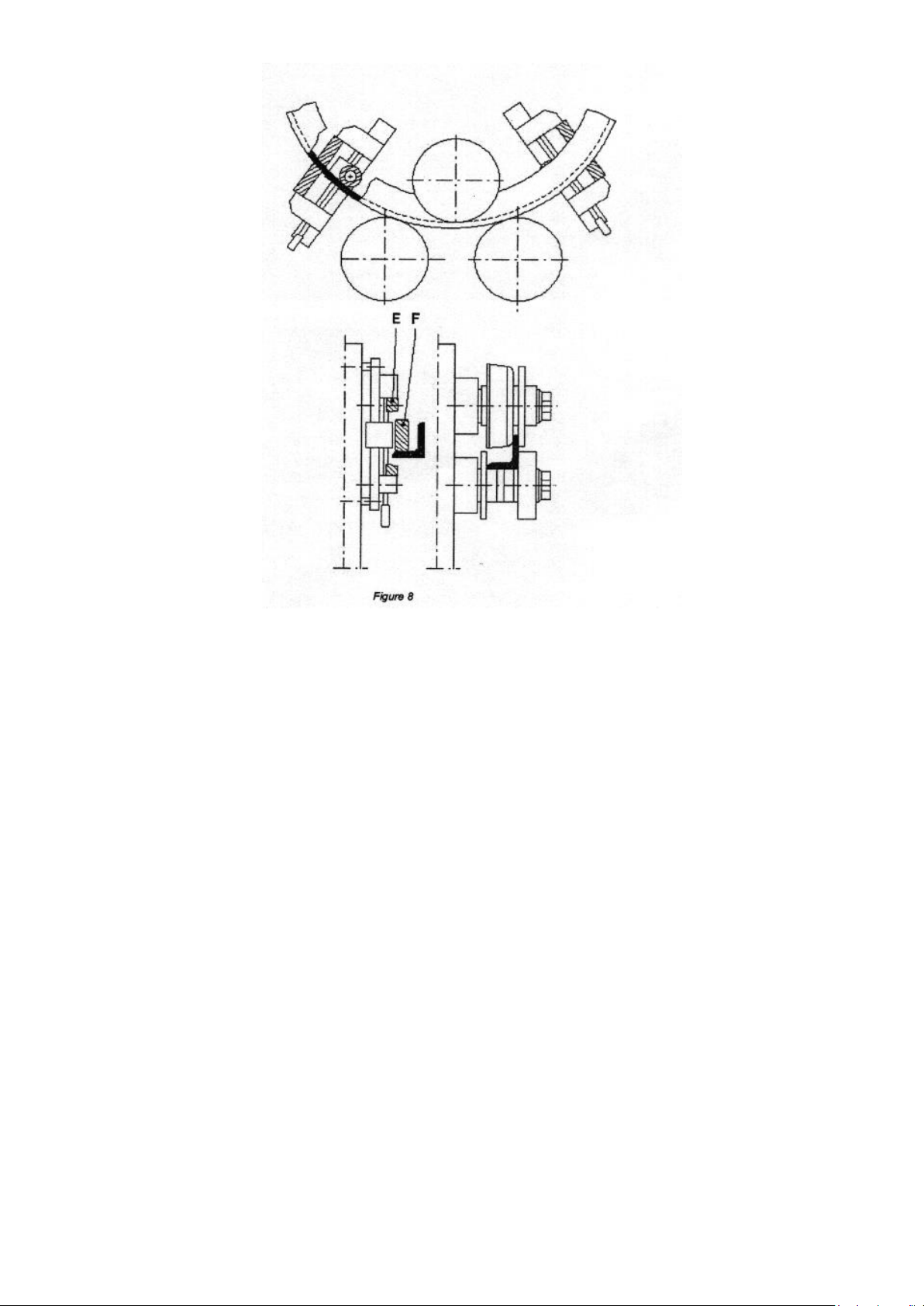
Figure 8 shows the use of "Leg-In Bending Guide Rolls” These guide rolls are special accessory for
bending leg-in (angle) material and are available for extra cost. They are adjustable for any size of
material and easy to use, Special rolls are recommended for any batch jobs of leg-in or leg-out
material. Some of the angle materials can be bent with standard rolls.
Operational hints
• Always clean the rolls and the material of dust, dirt and grease for bending
• If you are bending a pipe do not rotate the pipe while bending
• We advise you to fill the profiles or pipes with sand or any similar material if they have a wall thick-
ness of less than 2 mm
• Do not overload the machine and use special rolls for profiles as well as pipes
• Operate safely keeping in mind the third party people around the machine
• Leave enough workspace around the machine
• The machine can also work horizontally for extremely large diameters
• The machine has double-speed motor.
Page 19
19
10.0 MAINTENANCE
A suitable maintenance is also compulsory to get a maximum
machine life and optimal working conditions for machine’s
efficiency.
A regular maintenance interventions should be performed by a
well-trained safety responsible and if possible by a mechanical
engineer.
Attention: Regular and scheduled maintenance
interventions cannot be performed by running
machine. The main switch must be turned off.
Besides, a warning signal telling, “DO NOT AC-
TIVATE - MACHINE IN MAINTENANCE” must be
clearly visible on the machine.
Attention: Any processing system, which may
danger the machine safety, must be avoided.
As the machine does not include any kind of hydraulic system, it is simple to lubricate its functional
parts as shown in the below.
• Firstly, turn off the machine if it is active by moving the main switch “0” on the electric box.
• Remove the back lid by dismantling its screws.
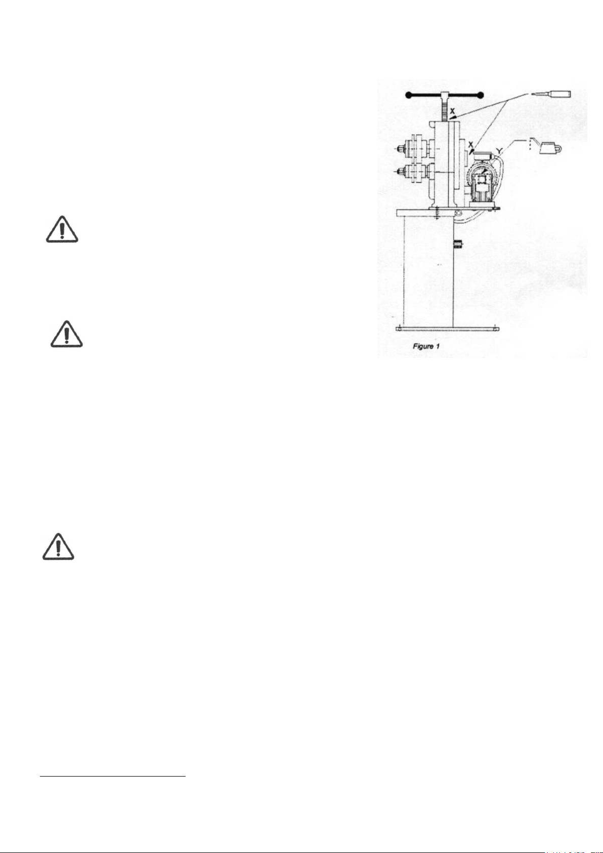
• Grease the power joints inside the machine with the help of an oilfeeder ().
• Also grease the upper roll adjustment shaft (shown by X points in figure 1)().
• Lubricate the reduction gearbox with OIL SAE 30 (illustrated by point Yin figure 1).
• After the lubrication, assemble again the back lid and the protections.
• Restart the machine according to the start procedure, and check if there are any anomalies due
to faults or unintentional tampering during maintenance.
Attention: For replacement of oil, use a funnel with a filter in order to avoid that impurities
enter into the gearbox or among the other movable parts and damage the good functioning
of the machine.
Internal cleaning of the electric box is also needed and must be done like in the following:
• Turn off the machine moving the main switch on the electric box “0”.
• Disconnect the mains supply from the electric board.
• Open the electric box lock.
• Do not use liquid detergents while cleaning the electric box inside.
• Check the connections to the terminals of the different devices.
• Tighten any loose connections.
• Close the door of the electric box and check if it is closed perfectly enough.
• Connect the electric board to the mains.
Restart the machine according to the start procedure, and check if there are any anomalies because
of faults or unintentional tampering during maintenance
(): Use commercial grease for lubrication and make this operation once per month.
(): Use “MOBIL VACTRA OIL No: 2” or equivalent and lubricate this shaft once per week.
Page 20
20
11.0 LUBRICATION
General Maintenance
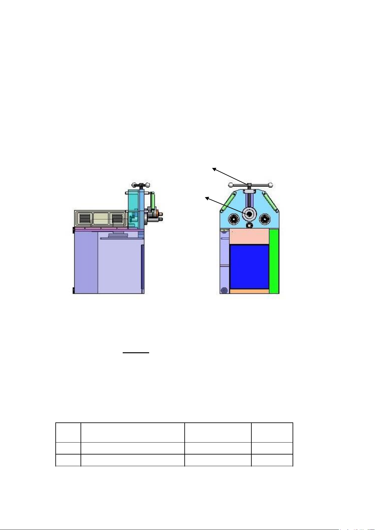
The machine needs to be lubricating periodically for efficient working and longer to be lubricated
periodically for efficient working and a longer life. You can see the points of lubrication list below and a
lubrication chart for periods of lubricated
Lubricate chart
IMPORTANT
The rolls of the machine must NEVER be greased or lubricated. Because then the rolls will slip the
material and will not bend. Always keep the rolls clean and free from grease or any lubricant. AIso
make sure that the material is free from grease and dirt.
These points must be greased periodically at least once a month or more if daily usage exceeds 8
hours a day. Note that some of these points are actually inside the machine cover and the front cover
must be removed in order to reach them. Any standard commercial grease can be used for
lubrication.
1
2
Num
ber
Part no period
what to do
1 Top roll Adjusment Every Week Grease
2 Top Roll Housing Once a month Grease
Page 21
21
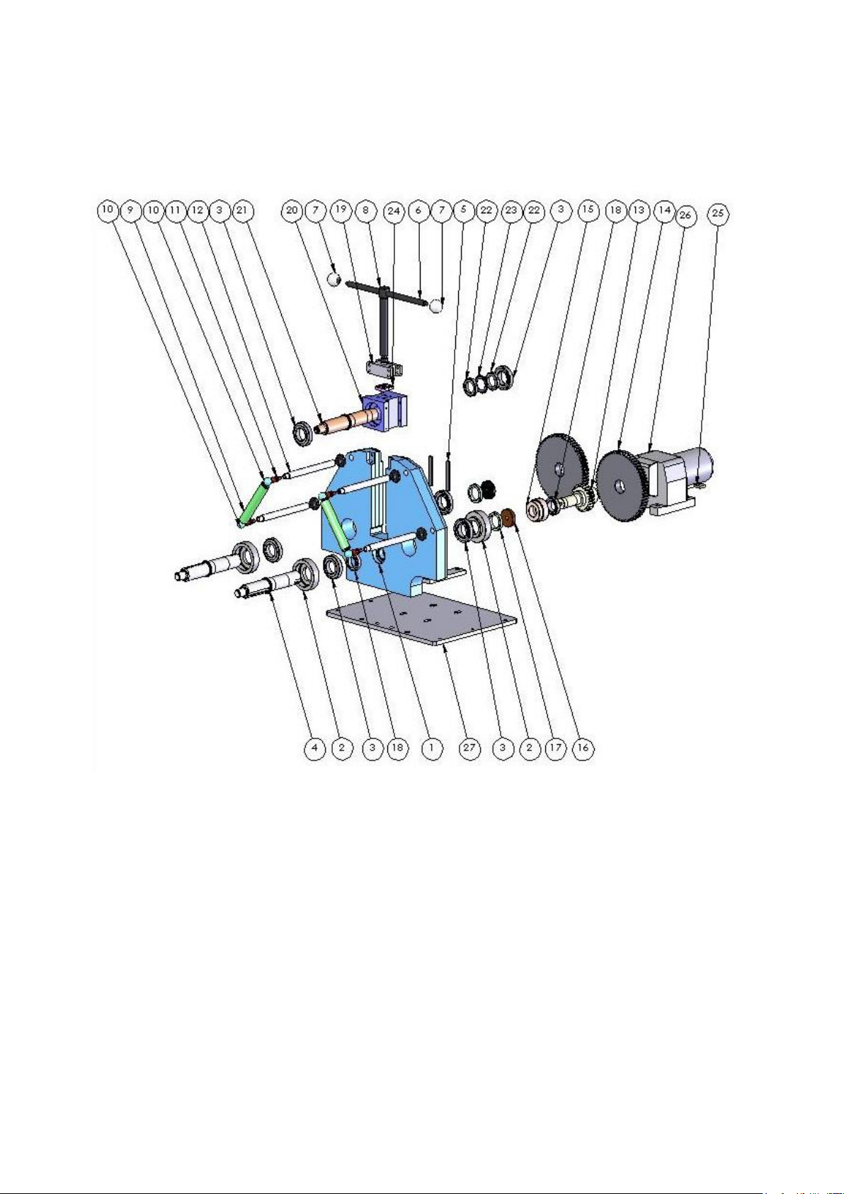
Part List
Page 22
22
12.0 SPECIAL ACCESSORIES FOR MODEL PV 35
NO
PSC
PART NR.
PART NAME
1 1 192-35-10-001
STEEL FRAME
2 4 192-35-12-107
FLANGE
3 6 ---------
BEARING
4 2 192-35-12-001
BOTTOM SHAFT
5 2 192-35-12-051
KEY 6 1
192-35-13-002
TOP ROLL ADJUTMENT HAND
LEVER
7 2 192-35-13-007
KNOB
8 1 192-35-13-001
TOP ROLL ADJUSTMNET
9 2 192-35-11-001
GUIDE ROLL JOINT
10 4 192-35-11-002
GUIDE ROLL JOINT
11 4 192-35-11-003
GUIDE ROLL JOINT ADJUSTMENT
SCREW
12 4 192-35-11-004
LATERAL SIDE SCREW
13 1 192-35-12-151
HANDLE
14 2 192-35-12-152
GEAR
15 1 192-35-12-052
GEAR
16 2 192-35-12-108
BUSHİNG
17 2 -------
SPACER
18 2 -------
BEARING
19 1 192-35-12-004
BEARING CHOCK
20 1 192-35-13-004
TOP SHAFT BLOCK
21 1 192-35-12-002
TOP SHAFT
22
2
DIN 1804 - M45x1.5
- N
SAFETY NUT
23 1 192-35-13-005
MB
24 1 192-35-12-006
UPPER PLATE
25 1 192-35-10-000
MOTORS
26 1 Reduktor
REDUCER
27 1 192-35-16-052
BOTTOM PLATE
28 2 192-35-16-053
FRAME BOTTOM PLATE
Various special rolls:
1. For bending
2. Aluminum profiles
3. Pipes, tubes
4. Hollow sections
5. Angle sections
Page 23
23
13.0 ELECTRIC DIAGRAM
Page 24
24
Page 25
25
Page 26

26
Warranty
Guarantee
If within 2 year of purchase this machine supplied by SCANTOOL A/S becomes defective due to
faulty materials or workmanship we guarantee to repair or replace the machine or defective part or
parts free of charge provided that:
1. The product is returned complete to one of our Service Branches or Official Service
Agents.
2. The product has not been misused or carelessly handled and in particular has not been
used in a manner contrary to the operating instructions.
3. Repairs have not been made or attempted by other than our own Service Staff or the staff
of our Official Service Agents.
4. Documentary proof of purchase date is produced when the goods are handed in or sent
for repair.
5. Wear parts are not covered by the warranty
SCANTOOL A/S offers you five years guarantee on the electrical motor if the motor becomes
defective or even burns-out within the first 5 years from date of invoice.
 Loading...