

Scantech VEGA V-1010 User Manual
U s e r ’ s M a n u a l
VEGA V-1010 Linear Imager
Handheld Bar code Scanner

Notice The manufacturer shall not be liable for technical or
editorial errors or omissions contained herein; nor for
incidental or consequential damages in connection with the
furnishing, performance or use of the publication
HEAD QUARTER
CHAMPTEK INCORPORATED
5/F, No.2 Alley 2, Shih-Wei
Lane,
Chung Cheng Rd., Hsin Tien
City,
Taipei 231,Taiwan
Tel:+886-2-2219-2385
Fax:+886-2-2219-2387
E-mail:sales@champtek.com
www.champtek.com
C
hina
CHAMPTEK INCORPORATED
#901, No. 39, Wuzhong Rd.,
Shanghai 200235, China
Tel: +86-21-5489-0021
Fax: +86-21-5489-1833
EMEA
SCANTECH-ID BV
Nijverheidsweg Noord 60-34
3812 PM Amersfoort
The Netherlands
Tel:+31-33-4698400
Fax:+31-33-4650615
E-mail:info@scantech-id.com
www.scantech-id.com
User’s Installation and Configuration
Manual
Scantech-ID VEGA

Copyright © 2009, Scantech-ID BV.
This manual is copyrighted, with all rights reserved. Under the copyright
laws, this manual may not, in whole or in part, be copied, photocopied,
reproduced, translated or converted to any electronic medium or machine
readable form without prior written consent of Scantech-ID BV.
Limited Warranty
Under all circumstances this manual should be read attentively, before
installing and/or using the product. In no event shall Scantech-ID BV be
liable for any direct, indirect, special, consequential or incidental
damages arising out of the use or inability to use this documentation or
product, even if advised of the possibility of such damages. In particular,
Scantech-ID BV shall not be liable for any hardware, software, or data
that is stored or used with the product, including the cost of repairing,
replacing or recovering the above. Scantech-ID BV reserves the right to
change parts of the device at any time without preceding or direct
announcement to the client.
Scantech-ID BV reserves the right to revise this manual, and to make
changes in the contents without obligation to notify any person or entity
of the revision or change. A serial number appears on the product. Make
sure that this official registration number has not been removed. It
should be used whenever servicing by Scantech-ID BV or an authorized
Scantech dealer is necessary.
P/N A270003 V1.0 July 2010

1
Table of contents
Introduction .......................................... 6
Chapter 1 Product Safety ............................. 7
1.1 Safety & caution ......................... 8
1.2 FCC warning .............................. 9
Chapter 2 General Description ....................... 10
2.1 Use of the VEGA ......................... 11
Chapter 3 Installation of the VEGA .................. 12
3.1 V-1010 Unpacking ........................ 13
Chapter 4 Cover Display ............................. 14
4.1 SETUP Cover Display ..................... 15
4.1.1 Message Format ............................ 15
4.1.2 Change Cover Display ...................... 16
Chapter 5 Configuring the VEGA ...................... 19
5.1 Preface ................................. 20
5.1.1 Changing Scanner Settings with Programming
Codes ..........................................20
5.1.2 Programming Flow Chart .................... 21
5.2 Factory default setting ................. 22
Chapter 6 Programming Codes ......................... 23
6.1 General Process ......................... 24
6.1.1 Abort Configuration ....................... 24
6.1.2 Recall .................................... 24
6.1.3 Set All Default ........................... 25
6.1.4 Version Information ....................... 25
6.2 Interface selection ..................... 26

2
6.2.1 Interface ................................ 26
6.3 SCANNER operation ........................ 26
6.3.1 Reading Mode ............................. 26
6.3.2 Good Read LED Control .................... 27
6.3.3 Beeper Option ............................ 27
6.3.4 Reading Level ............................ 28
6.3.5 Accurany / Redundant Scan ................ 28
6.3.6 Sensitivity of Continuous Reading ........ 28
6.3.7 Reverse Output Characters ................ 29
6.4 RS232 mode parameters .................... 29
6.4.1 Baud Rate ................................ 29
6.4.2 Data/Stop Bits ........................... 30
6.4.3 Parity ................................... 30
6.4.4 Handshaking .............................. 31
6.5 Keyboard Wedge mode parameters ........... 32
6.5.1 Terminal Type ............................ 32
6.5.2 Country/Language ......................... 33
6.5.3 Upper/Lower Case ......................... 34
6.5.4 Capslock Detection ....................... 34
6.5.5 Character by ALT Method .................. 35
6.5.6 Select Numerical Pad ..................... 35
6.5.7 Interscan Code Delay ..................... 36
6.6 Output Characters ........................ 37
6.6.1 Select Terminator ........................ 37
6.7 Code Type ................................ 38
6.7.1 Barcode Selections ....................... 38
6.8 UPC/EAN/JAN Parameters ................... 42
6.8.1 Reading Type ............................. 42

Scantech-ID VEGA Linear Imager 3
6.8.2 Supplemental Setup ........................ 43
6.8.3 Check Digit Transmission .................. 44
6.9 Code 39 parameters ...................... 45
6.9.1 Type of Code .............................. 45
6.9.2 Check Digit Transmission .................. 45
6.9.3 Output Start/Stop Character ............... 45
6.9.4 Decode Asterisk ........................... 46
6.9.5 Set Up Code Length ........................ 46
6.10 Code 128 parameters ..................... 48
6.10.1 Reading Type .............................. 48
6.10.2 Check Digit Transmission .................. 48
6.10.3 Append FNC2 ............................... 48
6.10.4 Set Up Code Length ........................ 49
6.11 Interleave 2 of 5 parameters ............ 51
6.11.1 Check Digit Transmission .................. 51
6.11.2 Set Up Number of Character ................ 51
6.11.3 Brazilian Banking Code .................... 51
6.11.4 Set Up Code Length ........................ 52
6.12 Industrial 2 of 5 parameters ............ 54
6.12.1 Reading Type .............................. 54
6.12.2 Check Digit Transmission .................. 54
6.12.3 Set Up Code Length ........................ 55
6.13 Matrix 2 of 5 parameters ................ 57
6.13.1 Check Digit Transmission .................. 57
6.13.2 Set Up Code Length ........................ 57
6.14 CODABAR/NW7 parameters .................. 59
6.14.1 Set Up Start/Stop Characters upon
Transmission ...................................... 59

4
6.14.2 Transmission Type of Start/Stop .......... 59
6.14.3 Set Up Code Length ....................... 60
6.15 Code 93 parameters ....................... 62
6.15.1 Check Digit Transmission ................. 62
6.15.2 Set Up Code Length ....................... 62
6.16 Code 11 parameters ....................... 64
6.16.1 Check Digit Transmission ................. 64
6.16.2 Set Up Code Length ....................... 64
6.17 MSI/plessey code parameters .............. 66
6.17.1 Check Digit Transmission ................. 66
6.17.2 Set Up Code Length ....................... 66
6.18 Telepen PARAmeters ....................... 68
6.18.1 Type of Code ............................. 68
6.18.2 Check Digit Transmission ................. 68
6.18.3 Set Up Code Length ....................... 68
6.19 GS1 databar PArameters ................... 70
6.19.1 Check Digit Transmission ................. 70
6.19.2 Application ID ........................... 70
6.19.3 Symbology ID ............................. 70
6.20 GS1 databar Limited PArameters ........... 71
6.20.1 Check Digit Transmission ................. 71
6.20.2 Application ID ........................... 71
6.20.3 Symbology ID ............................. 71
6.21 Gs1 Databar expanded parameters .......... 72
6.21.1 Symbology ID ............................. 72
Chapter 7 Miscellaneous Parameters .................. 73
7.1 Bar Code ID .............................. 74
7.1.1 Default Barcode ID ....................... 74

Scantech-ID VEGA Linear Imager 5
7.1.2 User Define Code ID ....................... 75
7.2 preambles and postambles Insertion ...... 77
7.2.1 Setup Insertion ........................... 77
7.2.2 Insertion Set Number ...................... 78
7.2.3 Symbologies Selection ..................... 79
7.2.4 Character Position to be Insertion ........ 81
7.2.5 Characters to be Inserted ................. 81
7.3 Character deletion ...................... 82
7.3.1 Deletion Set Number ....................... 83
7.3.2 Code Type to be Delete .................... 84
7.3.3 Character Position to be Delete ........... 86
7.3.4 Number of Characters to be Delete ......... 86
Appendixes ........................................... 87
A. DECIMAL VALUE TABLE ..................... 88
B. ASCII TABLE ............................. 89
C. FUNCTION KEY TABLE ...................... 95
D. Readable Symbologies .................... 96
E. Technical Specifications ................ 97
F. Scan map ................................ 98
G. Test Symbologies ....................... 100
H. Overview Model Numbers ................. 102

6
Introduction
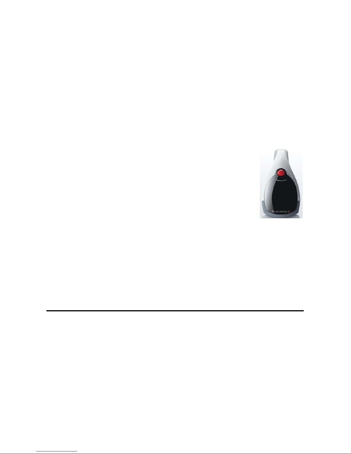
VEGA is a cutting-edge gun-type barcode scanner which is
designed specifically for retail market. To the brand
new series of VEGA, we add on more user-friendly
functions with detachable cable that makes it more
easily to be operated by the customers.
Speaking of the performance, this scanner supports
middle to long range mode. For specification of VEGA
which supports the reading depth up to 27 centimeter,
scan rate is up to 700 scans / per second.
The new VEGA scanner has most modern design with the
decorative cover display on the top of the scanner that
will enhance the looks of the checkout counter in the
retail market. This magnificent design allowed end-users
to display their product information or any relevant
commercial message in the cover display. This advanced
mechanical design truly creates a win-win solution for
both POS retail systems and consumers.
In short, VEGA is absolutely a high performance gun-type
scanner, which provides the customer with the most costeffective solution in the market. It is perfectly
suitable and definitely the best choice for any
retailers using POS environment.
Quality and Durability
The VEGA comes with the same top quality as all other
Scantech-ID products. So at a very competitive price the
same quality and performance of more expensive products
is available. Due to the high MTBF times of every
component a long and service free operation time is
secured.
Connectivity
The VEGA is available into interface types, RS232
interface, USB interface and also with Bluetooth
technology, so there is always a solution to connect the
Vega to your POS system.

7
Chapter 1 Product Safety

8 Installation of the VEGA V-1010
1.1 SAFETY & CAUTION
1. Please read the following safety statement carefully.
2. Please preserve this user manual for reference
sometime.
3. Before cleaning the VEGA, the users must cut off all
AC power. Do not use liquid or spray type of
detersive to clean the VEGA. Please use dampish
cotton cloth to clean the VEGA.
4. The outlet must set nearby the VEGA for connecting
power easily.
5. Keep the VEGA dry to avoid short circuit.
6. During installation you must fix the equipment at
solid table to avoid damage caused by falling.
7. Before inserting power please ensure the voltage is
healthy to the equipment.
8. For safety please tie wire well and don’t put
anything on the wire.
9. If you don’t use this equipment for long time, please
cut off the power to avoid damage from surge power.
10. Don’t spray any liquid on this scanner because it may
cause a fire or short circuit.
11. Please do not open the equipment. For safety only the
qualified serviceman can open the equipment.
12. If there are the following situations please contact
with the qualified serviceman to check this equipment.
(a) The damage of wire or pin of power supply.
(b) Some Liquid infiltrate into the equipment.
(c) The equipment has been exposed to wet
environment.
(d) The equipment can’t work well.
(e) The equipment has any obvious damage, making the
VEGA working abnormally.
13. Don’t storage the VEGA at the temperature lower than
-20°C (-4°F) or higher than +70°C (158°F) to avoid
any damage.

Scantech-ID VEGA Linear Imager 9
1.2 FCC WARNING
This equipment complies with the requirements in Part
15 of FCC.
Any operation must comply with the conditions below:
(a) The equipment will not cause any severe interference.
(b) The equipment can avoid any interference from
environment.
Statement:
This product is classified as B class product.
In environment this product may cause some
interference. In this situation the user may
do something to avoid interference.

10 Installation of the VEGA V-1010
Chapter 2 General Description
Scantech-ID VEGA Linear Imager 11
2.1 USE OF THE VEGA
THE VEGA IS VERY ERGONOMIC AND MODERN DESIGNED AND VERY
USER FRIENDLY. IT CAN BE CONNECTED TO YOUR POS OR HOST
SYSTEM TROUGH A RS232 CABLE, KBW CABLE, USB CABLE OR WITH
BLUETOOTH WIRELESS.
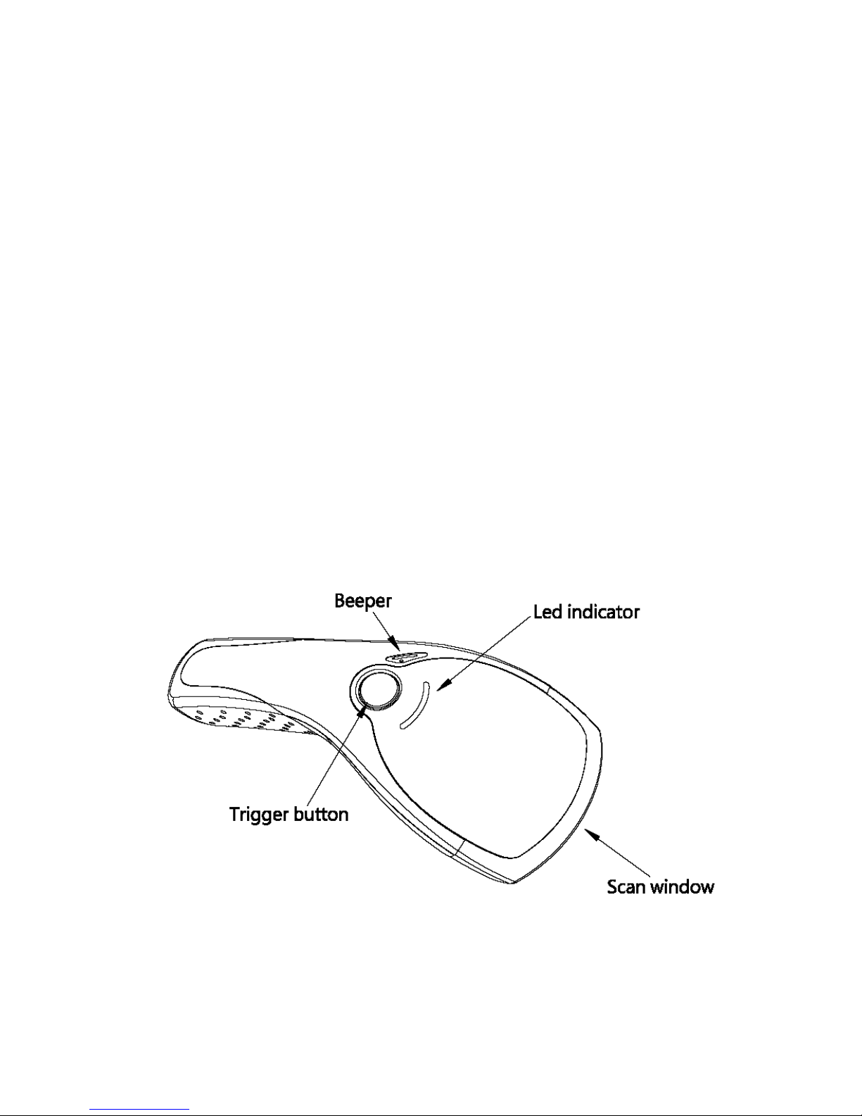
To read a bar code, you simply press the red trigger
button and aim the beam to the bar code. But you need to
position the beam so that it falls across all bars in the
1D barcodes. You will hear one beep and the green LED
indicator will lights on after scan successfully.
The programming of the VEGA is very easy, you can set-up
the VEGA by scan all necessary programming codes one time
that meet applications, the settings are directly saved
permanently, and all settings can be disabled after scan
reset factory default.
THANKS TO THE POWER FULL DECODING PROCESSOR, THE VEGA CAN
DECODE ALL MAJOR 1D CODES.

12
Chapter 3 Installation of the VEGA

Scantech-ID VEGA Linear Imager 13
3.1 V-1010 UNPACKING
Unpack the VEGA as follows:
1. Take the VEGA and its accessories out of the box.
2. Remove the packing material.
3. Check the packing list to make sure you have received
all of the items ordered.
Standard Shipment Package
a. VEGA Linear Imager Handheld Bar code Scanner
b. Communication Cable (RS-232 or Keyboard wedge or
USB)
c. Vega Stand
d. User Manual
e. Transparent Cover Plate
4. Visually inspect the VEGA and accessories for any
evidence of physical damage.
5. If anything is missing or appears to be damaged,
immediately contact your dealer.
ATTENTION
Store the packing material and boxes: it should
be used whenever the VEGA is transported for
servicing.

14 Configuring the VEGA
Chapter 4 Cover Display
Scantech-ID VEGA Linear Imager 15
4.1 SETUP COVER DISPLAY
The VEGA scanner has the opportunity to change the
decorative cover display on the top of the scanner into a
display that can show our own commercial message.
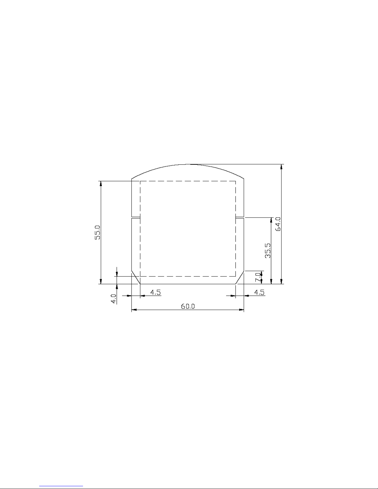
4.1.1 Message Format
Create your own commercial message with the following
outline format, use thicker paper
16 Configuring the VEGA
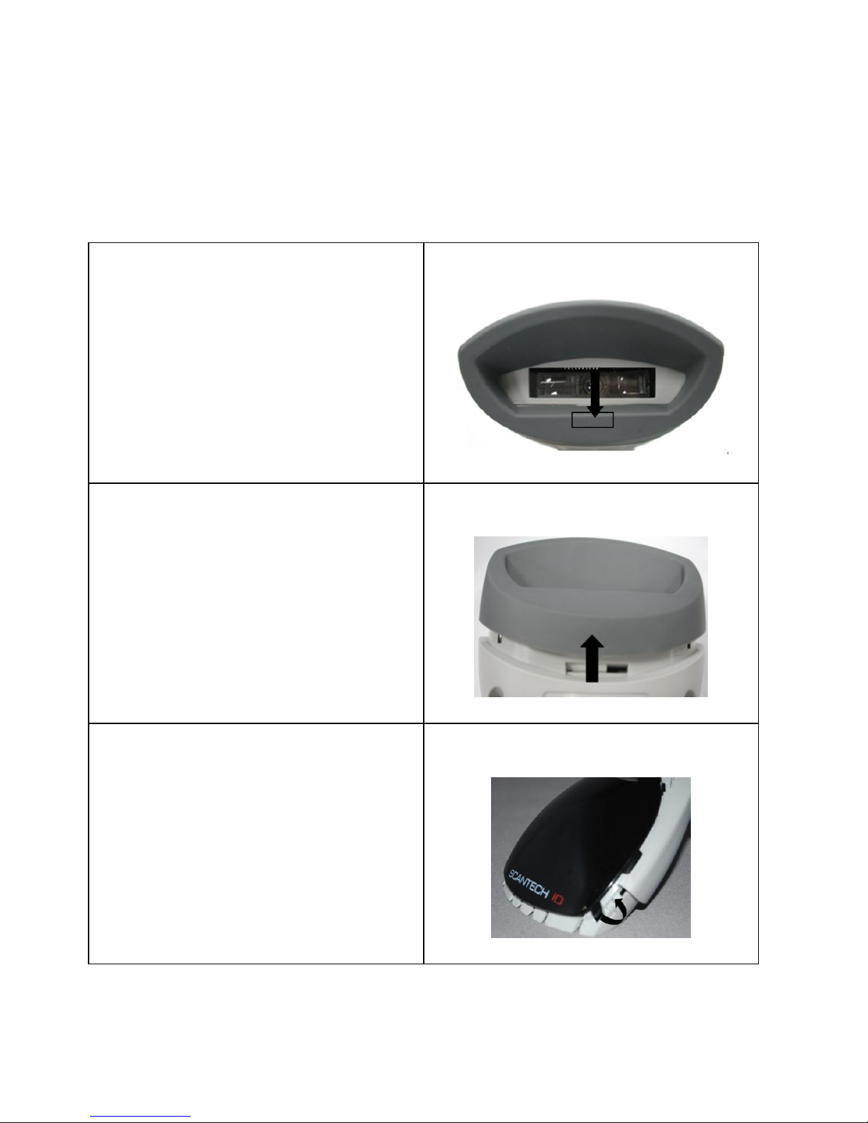
4.1.2 Change Cover Display
Follow the next instruction steps to change the black
Cover Display into the transparent Cover Display, so that
your customers can read your own commercial massage.
Step 1:
Press out the front rubber
lid toward the arrow.
➀
Step 2:
Pull out the front rubber
lid off the main unit.
➁
Step 3:
Press out top cover rim
from the inner lock.
➂
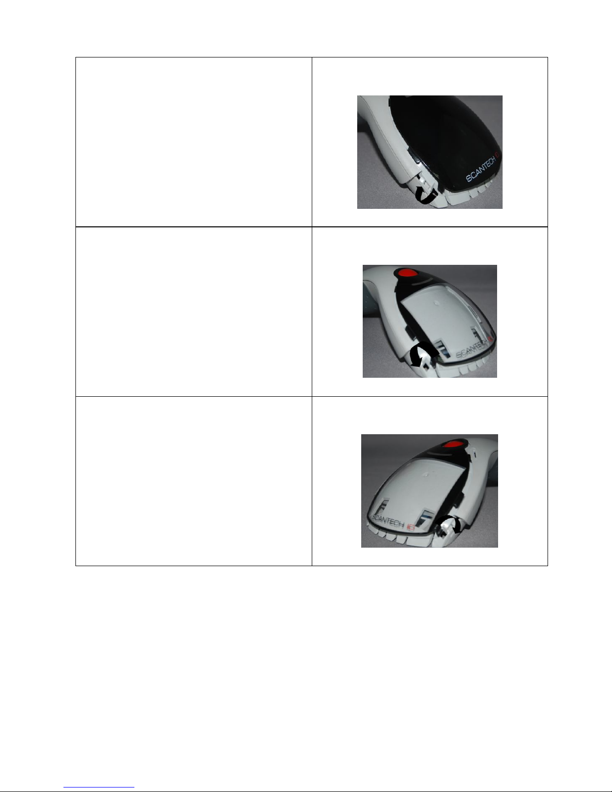
Scantech-ID VEGA Linear Imager 17
Step 4:
Press out the other side of
inner lock and remove the
complete cover.
➃
Step 5
Assemble transparent top
cover rim into inner lock.
➄
Step 6
Assemble another side
transparent top cover rim
into the inner lock.
➅
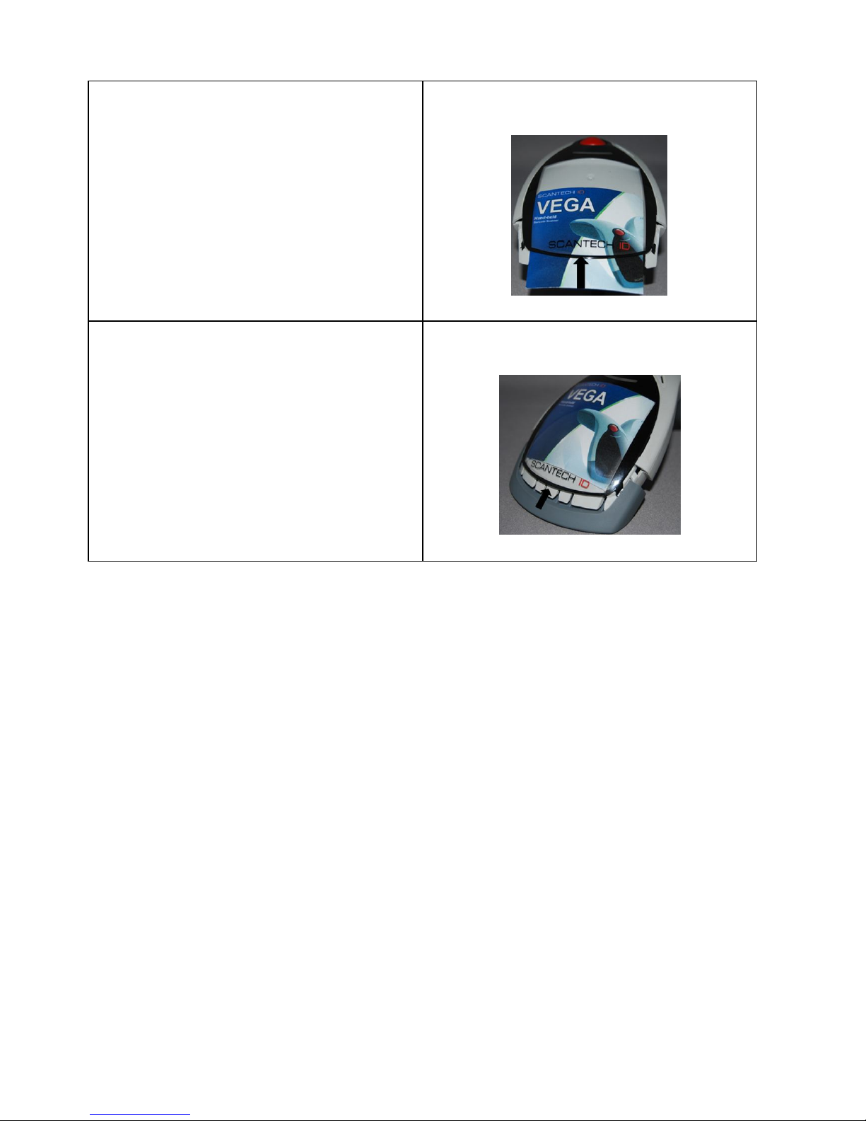
18 Configuring the VEGA
Step 7
Insert your commercial
message card into the top
cover toward the arrow.
➆
Step 8
Assemble the front rubber
lid into the main unit
toward the arrow.
➇

Scantech-ID VEGA Linear Imager 19
Chapter 5 Configuring the VEGA

20 Configuring the VEGA
5.1 PREFACE
How to configure the VEGA:
The Barcode programming feature gives the possibility to
change the VEGA scanner settings with use programming
labels.
5.1.1 Changing Scanner Settings with
Programming Codes
You can set-up your VEGA by scan all necessary
programming codes for parameters that meet applications.
In order to change the scanner settings please follow the
sequence below:
1. Power-up the scanner.
2. Open the scanner programming mode by scanning
Start Configuration.
3. Change scanner settings by scanning any of the
programming code that meet applications.
4. Close the scanner programming mode by scanning
End Configuration.
5. Save configuration by scanning
Save Parameters
An Example:
For changing the Baud rate to 38400 the following codes
must be scanned successively:
Start configurationBaud rate 38400End configuration
Save Parameters
After reading a valid programming code the scanner will
give a double High beep and the green led indicator will
lights on.
By scanning “Set All Default” label, the settings will go
back to the factory default settings.
Scantech-ID VEGA Linear Imager 21
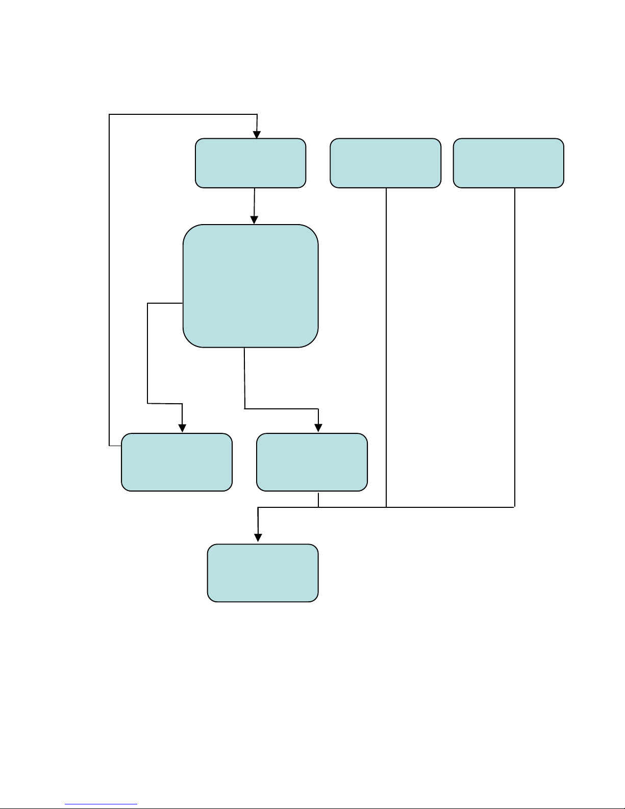
5.1.2 Programming Flow Chart
Start
Configuration
Recall
Parameters
Set all Default
Interface
Selection
Communication
Parameters
Bar codes
Parameters
Misc. Parameters
etc.
End
Configuration
Abort
Configuration
Save
Parameters

22 Configuring the VEGA
5.2 FACTORY DEFAULT SETTING
The VEGA is set default with the following settings:
RS232 COMMUNICATION
DEFAULT
Baud rate
9600
Parity
None
Data bits
8
Stop bits
1
RTS/CTS
Off
Postamble
<CR+LF>
DECODER SELECTION
DEFAULT
All UPC/EAN/JAN
On
Code 11
Off
Code 39
On
Code 39 Full ASCII
Off
Code 32 / Italian Pharmacy
Off
Code 128
On
Codabar/NW7
On
GS1 Databar RSS-14
Off
GS1 Databar Expanded
Off
GS1 Databar Limited
Off
Interleave 2 of 5
On
Industrial 2 of 5
Off
Matrix 2 of 5
Off
MSI/Plessey
Off
Telepen
Off
China Postage
Off
CODE IDENTIFIERS
DEFAULT
Code Identifiers
Off
The factory defaults settings are shown with <> and bold
in the following chapters.

23
Chapter 6 Programming Codes
24 Miscellaneous Parameters
6.1 GENERAL PROCESS
1
Power up the Scanner
2
Scan the Start of Configuration bar
code
3
Scan the bar code for the desired feature. You can scan
all features before scanning End of Configuration.
4
Scan End of Configuration bar code
5
Scan Save Parameters bar code
6.1.1 Abort Configuration
Terminate current programming
status.
6.1.2 Recall
Replace the current parameters
by the parameters saved last time

Scantech-ID VEGA Linear Imager 25
6.1.3 Set All Default
Set all the parameters to the
factory default settings
6.1.4 Version Information
Display the Scanner Decoder
version
information and date code
26 Miscellaneous Parameters
6.2 INTERFACE SELECTION
6.2.1 Interface
<Keyboard Mode>
RS232 Mode
USB Mode
6.3 SCANNER OPERATION
6.3.1 Reading Mode
<Good Read OFF>
Trigger ON/OFF
Continuous/Trigger OFF
Continuous/Auto Power ON
Flash
 Loading...