

Scantech V-1020BT User Manual

U s e r ’ s M a n u a l
Scantech
VEGA BT C1/C2 Area Image Barcode Scanner with
V-1020BT
Handheld Bar Code Scanner

EMEA
SCANTECH-ID BV
Nijverheidsweg Noord 60-34
3812 PM Amersfoort
The Netherlands
Tel:+31-33-4698400
Fax:+31-33-4650615
E-mail:info@scantech-id.com
www.scantech-id.com
Head Quarter
CHAMPTEK INCORPORATED
5/F, No.2 Alley 2, Shin-Wei Lane,
Chung Cheng Rd., Hsin Tien City 231,
Taipei, Taiwan
Tel:+886-2-2219-2385
Fax:+886-2-2219-2387
E-mail:sales@champtek.com
www.champtek.com
China
CHAMPTEK INCORPORATED
#901, No. 39, Wuzhong Rd., Shanghai
200235, China
Tel: +86-21-5489-0021
Fax: +86-21-5489-1833
Notice The manufacturer shall not be liable for technical or editorial errors or omissions contained
herein; nor for incidental or consequential damages in connection with the furnishing, performance
or use of the publication
User’s Installation and Configuration Manual
Scantech-ID VEGA

This equipment has been tested and found to comply with the limits for a Class B digital device, pursuant to part 15 of
the FCC rules. These limits are designed to provide reasonable protection against harmful interference in a residential
installation. This equipment generates, uses and can radiate radio frequency energy and, if not installed and used in
accordance with the instructions, may cause harmful interference to radio communications. However, there is no
guarantee that interference will not occur in a particular installation. If this equipment does cause harmful interference
to radio or television reception, which can be determined by turning the equipment off and on, the user is encouraged
to try to correct the interference by one or more of the following measures:
-Reorient or relocate the receiving antenna.
-Increase the separation between the equipment and receiver.
-Connect the equipment into an outlet on a circuit different from that to which the receiver is connected.
-Consult the dealer or an experienced radio/TV technician for help.
You are cautioned that changes or modifications not expressly approved by the party responsible for compliance could
void your authority to operate the equipment.
FCC RF Radiation Exposure Statement:
1. This Transmitter must not be co-located or operating in conjunction with any other antenna or transmitter.
2. This equipment complies with FCC RF radiation exposure limits set forth for an uncontrolled environment.
FCC RF Radiation Exposure Statement:
1. This Transmitter has been demonstrated co-location compliance requirements with (key in : the type
of transmitter, eg. Bluetooth / Model No:V-1020BT) ).This transmitter must not be co-located or operating
in conjunction with any other antenna or transmitter.
2. This equipment complies with FCC RF radiation exposure limits set forth for an uncontrolled
environment.
Copyright © 2009 Scantech-ID BV
This manual is copyrighted, with all rights reserved. Under the copyright laws, this manual may not, in
whole or in part, be copied, photocopied, reproduced, translated or converted to any electronic medium
or machine readable form without prior written consent of Scantech-ID BV.
Limited Warranty
Under all circumstances this manual should be read attentively, before installing and/or using the product.
In no event shall Scantech-ID BV be liable for any direct, indirect, special, consequential or incidental
damages arising out of the use or inability to use this documentation or product, even if advised of the
possibility of such damages. In particular, Scantech-ID BV shall not be liable for any hardware, software,
or data that is stored or used with the product, including the cost of repairing, replacing or recovering the
above. Scantech-ID BV reserves the right to change parts of the device at any time without preceding or
direct announcement to the client.
Scantech-ID BV reserves the right to revise this manual, and to make changes in the contents without
obligation to notify any person or entity of the revision or change. A serial number appears on the
product. Make sure that this official registration number has not been removed. It should be used
whenever servicing by Scantech-ID BV or an authorised Scantech dealer is necessary.
P/N A270004 V1.0 May 2009

3
Table of contents
Table of Contents ......................................................................................... 3
Introduction ................................................................................................. 6
Chapter 1 Product Safety ........................................................................... 7
1.1 Safety & Caution .............................................................. 8
1.2 FCC Warning .................................................................... 9
1.3 Scanner Labelling ........................................................... 10
Chapter 2 General Description .................................................................. 11
2.1 Use of the VEGA ............................................................. 12
Chapter 3 Installation of the VEGA V-1020 .................................................. 13
3.1 Unpacking ..................................................................... 14
3.2 Mounting ....................................................................... 15
3.3 USB Driver ..................................................................... 16
Chapter 4 Installation of the VEGA V-1020BT .............................................. 17
4.1 Unpacking ..................................................................... 18
4.2 Cradle Installation ........................................................... 19
4.3 Set Up Bluetooth Communication ..................................... 20
Chapter 5 Cover Display ........................................................................... 23
5.1 Setup Cover Display ....................................................... 24

4 Product Safety
Chapter 6 Configuring the VEGA ................................................................ 29
6.1 Preface .......................................................................... 30
6.2 Factory Default Setting .................................................... 32
Chapter 7 Programming Codes ................................................................. 33
7.1 Return to Default ............................................................. 34
7.2 RS-232 Parameters ........................................................ 35
7.3 USB Mode ...................................................................... 38
7.4 Bluetooth Scanner Setup ................................................. 39
7.5 Bluetooth Cradle Setup ................................................... 43
7.6 Decoding Selection ......................................................... 45
7.7 EAN /UPC Parameters .................................................... 51
7.8 Code 11 Parameters ....................................................... 55
7.9 Code 39 Parameters ....................................................... 57
7.10 Code 93 Parameters ....................................................... 60
7.11 Code 128 / EAN 128 Parameters .................................... 61
7.12 Interleaved 2 of 5 Parameters ......................................... 63
7.13 MSi Code Parameters ..................................................... 65
7.14 Plessey Code Parameters ............................................... 67
7.15 Miscellaneous Parameters ............................................... 69
7.16 Preambles and Postambles ............................................. 70
7.17 Operating Settings .......................................................... 72

Scantech-ID VEGA Area Imager 5
Appendices ............................................................................................... 78
A ASCII Table ............................................................................................... 79
B Readable Symbologies .......................................................................... 81
C Technical Specifications ....................................................................... 82
D Scan map ................................................................................................. 84
E Test Symbologies .................................................................................. 86
F Overview Part Numbers ...................................................................... 89

6 Product Safety
Introduction
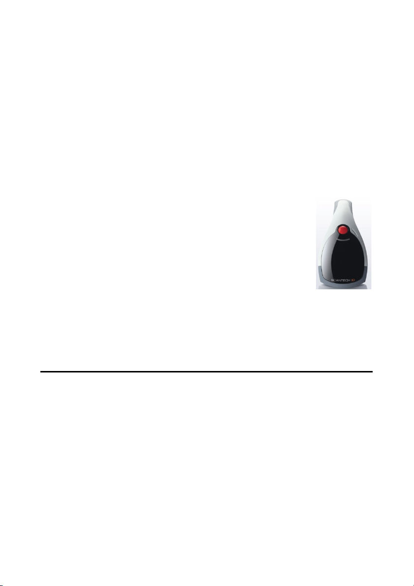
VEGA is a cutting-edge gun-type barcode scanner which is designed specifically
for retail market. To the brand new series of VEGA, we add on more user-friendly
functions with detachable cable that makes it more easily to be operated by the
customers.
Speaking of the performance, this scanner supports middle to long range mode.
For specification of VEGA which supports the reading depth up to 44 centimeters, scan rate is up to 200 scans / per second in linear emulation or 56
images / per second in 2D mode.
The new VEGA scanner has most modern design with the decorative cover
display on the top of the scanner that will enhance the looks of the checkout
counter in the retail market. This magnificent design allowed end-users to display
their product information or any relevant commercial message in the cover
display. This advanced mechanical design truly creates a win-win solution for both
POS retail systems and consumers.
In short, VEGA is absolutely a high performance gun-type scanner, which provides
the customer with the most cost-effective solution in the market. It is perfectly
suitable and definitely the best choice for any retailers using POS environment.
Quality and Durability
The VEGA comes with the same top quality as all other Scantech-ID products. So
at a very competitive price the same quality and performance of more expensive
products is available. Due to the high MTBF times of every component a long and
service free operation time is secured.
Connectivity
The VEGA is available in the interface types: RS-232 and USB, as well as with
Bluetooth technology, so there is always a solution to connect the Vega to your
POS system.

Scantech-ID VEGA Area Imager 7
Chapter 1 Product Safety

8 Product Safety
1.1 SAFETY & CAUTION
1. Please read the following safety statement carefully.
2. Please preserve this user manual for reference sometime.
3. Before cleaning the
liquid or spray type of detersive to clean the VEGA.
Please use dampish cotton cloth to clean the VEGA.
4. The outlet must set nearby the VEGA for connecting power easily.
5. Keep the VEGA dry to avoid short circuit.
6. During installation you must fix the equipment at solid table to avoid damage
caused by falling.
7. Before inserting power please ensure the voltage is healthy to the
equipment.
8. For safety please tie wire well and don’t put anything on the wire.
9. If you don’t use this equipment for long time, please cut off the power to
avoid damage from surge power.
10. Don’t spray any liquid on this scanner because it may cause a fire or short
circuit.
11. Please do not open the equipment. For safety only the qualified serviceman
can open the equipment.
12. If there are the following situations please contact with the qualified
serviceman to check this equipment.
(a) The damage of wire or pin of power supply.
(b) Some Liquid infiltrate into the equipment.
(c) The equipment has been exposed to wet environment.
(d) The equipment can’t work well.
(e) The equipment has any obvious damage, making the VEGA working
abnormally.
13. Don’t storage the VEGA at the temperature lower than -20°C (-4°F) or higher
than +70°C (158°F) to avoid any damage.
VEGA, the users must cut off all AC power. Do not use

Scantech-ID VEGA Area Imager 9
1.2 FCC WARNING
This equipment complies with the requirements in Part 15 of FCC.
Any operation must complies with the conditions below:
(a) The equipment will not cause any severe interference.
(b) The equipment can avoid any interference from environment.
Statement:
This product is classified as A class product.
In environment this product may cause some interference. In this
situation the user may do something to avoid interference.

10 Product Safety
Model Name
Serial Number
FCC ID:WOI-0852202T1000
V-1020BT
Scantech
This device complies with Part 15 of the FCC Rules. Operation is subject to the
following two conditions: (1) this device may not cause harmful interference
and (2) this device must accept any interference received, including
interference that may cause undesired operation
1.3 SCANNER LABELLING
Model Name :
V-1020BT
Serial Number: Product Serial No. (VA……..)
See Appendix I for more information in detail.

11
Chapter 2 General Description
12 General Description
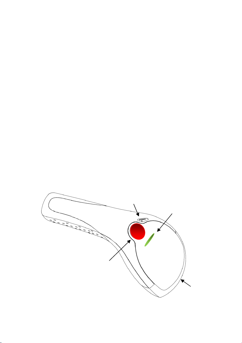
Led indicator
2.1 USE OF THE VEGA
VEGA is very ergonomic and modern designed and very user friendly. It can
The
be connected to your POS or Host system trough a RS-232 cable, USB cable or
with Bluetooth..
To read or bar code, you simply press the red trigger button and aim the beam to
the bar code or image. If you us the Area Imager version of the VEGA, it allows
you to position the hand held scanner beam in any direction, regardless of the
orientation of the bar code, and perform a good read on 1D and 2D bar codes.
You will hear one beep and the green LED indicator will lights on after scan
successfully.
The VEGA can also function as a camera by capturing images or image portions
of labels and other items. To control this function you can use VEGA Utility tool
The programming of the VEGA is very easy, you can set-up the VEGA by scan all
necessary programming codes one time that meet applications, the settings are
directly saved permanently, and all settings can be disabled after scan reset
factory default. Thanks to the powerful decoding processor, the VEGA can
decode all major 1D and 2D codes, 2D matrix symbols and postal codes.
Trigger button
Beeper
Scan window

13
Chapter 3 Installation of the VEGA V-1020

14 Installation of the VEGA V-1020
3.1 UNPACKING
Unpack the
VEGA as follows:
1. Take the VEGA and its accessories out of the box.
2. Remove the packing material.
3. Check the packing list to make sure you have received all of the items
ordered.
Standard Shipment Package
a. VEGA Area Imager Handheld Bar code Scanner
b. Communication Cable (RS-232 or USB)
c. Power Supply (if applicable)
d. Quick Start Guide
e. Stand
f. Transparent Cover Plate
4. Visually inspect the VEGA and accessories for any evidence of physical
damage.
5. If anything is missing or appears to be damaged, immediately contact your
dealer.
ATTENTION
Store the packing material and boxes: it should be used whenever
the VEGA is transported for servicing.
Scantech-ID VEGA Area Imager 15
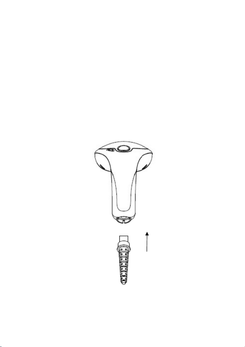
3.2 MOUNTING
Once you have unpacked all components, you can start installing the
VEGA.
Installing the VEGA is divided in different steps:
1. Connect the VEGA to the supplied communication cable (RJ45 side).
2. Connect the VEGA communication cable to the POS or HOST system.
3. Connect the Power supply (if needed) to Power cable inlet.
4. Plug the power supply into the AC outlet.
RJ 45 10 pin
Connector

16 Installation of the VEGA V-1020
3.3 USB DRIVER
In case you will use the
VEGA with USB virtual com port emulation, it is necessary
to install the correct USB driver on your POS or Host system, needed for correct
operation between your system and the VEGA scanner.
You can download this USB driver from the Scantech-ID web site:
www. Scantech-ID.com / Support / Downloads

17
Chapter 4 Installation of the VEGA V-1020BT

18 Installation of the VEGA V-1020BT
4.1 UNPACKING
Unpack the
VEGA as follows:
1. Take the VEGA and its accessories out of the box.
2. Remove the packing material.
3. Check the packing list to make sure you have received all of the items
ordered.
Standard Shipment Package
a. VEGA Area Imager Handheld Bar code Scanner Bluetooth
b. Communication Cable (RS-232, KBW or USB)
c. Power Supply
d. Quick Start Guide
e. Cradle
f. Transparent Cover Plate
4. Visually inspect the VEGA and accessories for any evidence of physical
damage.
5. If anything is missing or appears to be damaged, immediately contact your
dealer.
ATTENTION
Store the packing material and boxes: it should be used whenever
the VEGA is transported for servicing.
Scantech-ID VEGA Area Imager 19
I
nterface port
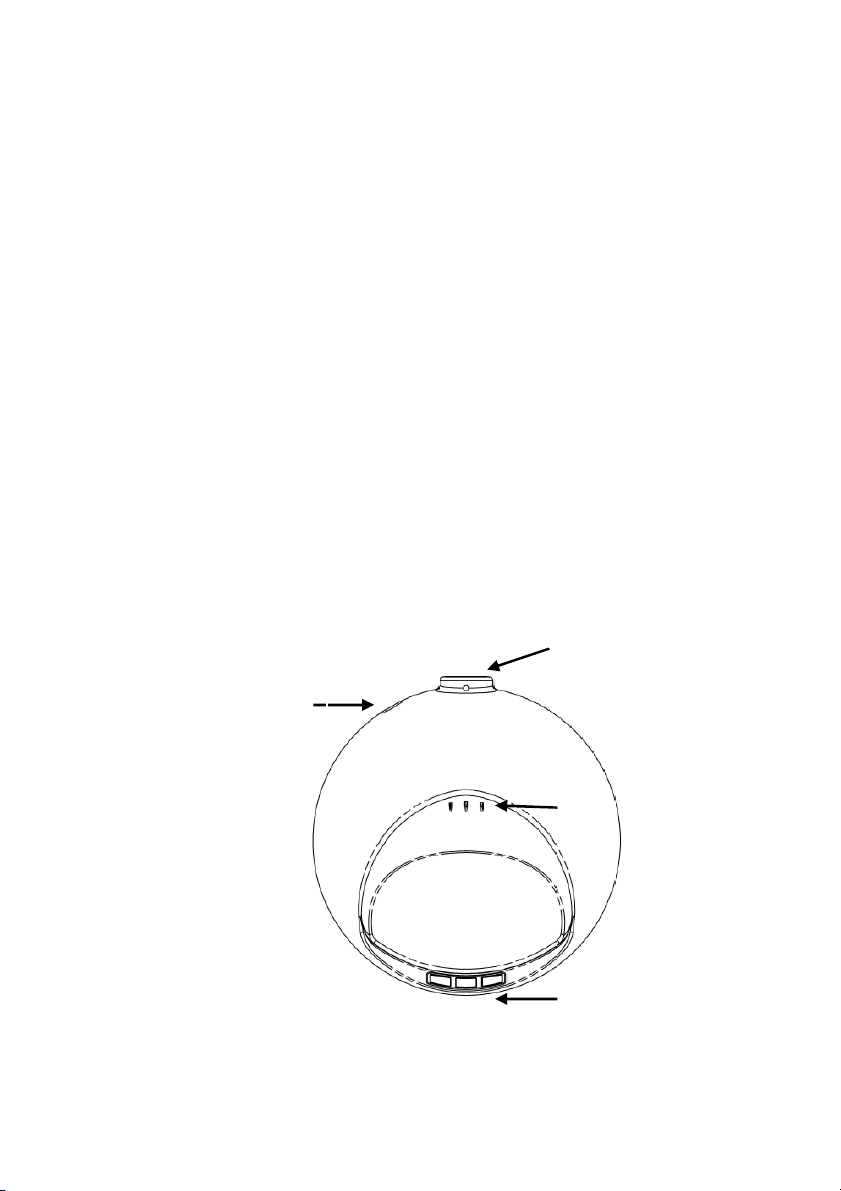
4.2 CRADLE INSTALLATION
To set up your
VEGA scanner with Bluetooth technology, please follow the next
steps.
1. Connect the supplied communication cable at the bottom side of the
cradle.
2. Connect the other side of the communication cable to the right connector
of your POS or HOST system.
3. Plug the external power supply into the power jack on the bottom of the
cradle.
4. Plug the power supply into the AC outlet.
5. Turn on your POS or HOST system.
6. Set up communication between the VEGA scanner and cradle.
To set up communication between VEGA scanner and cradle, see
chapter 4.3 Set up Bluetooth Communication.
Power jack
Charge pin connector

20 Installation of the VEGA V-1020BT
4.3 SET UP BLUETOOTH COMMUNICATION
Before the
VEGA scanner can be used for normal operation, Bluetooth
communication must be set up between the VEGA scanner and cradle.
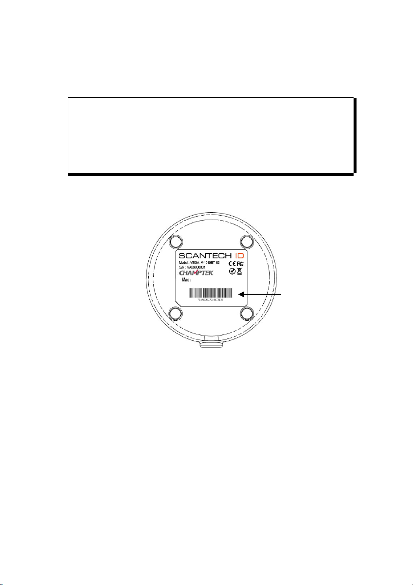
4.3.1 Pairing
Pairing refers to when a VEGA scanner has been linked or paired to a specific
cradle by scanning that cradle’s Bluetooth MAC address code, this Bluetooth MAC
address code is unique for each cradle. This address code is located on the
bottom side of the cradle. The pairing of a VEGA scanner to a cradle is one to
one. Only one VEGA scanner can be paired to a cradle at any point in time.
4.3.2 Set up Client Mode Communication
To set-up the communication between the VEGA scanner and the cradle follow
the next steps:
1. The VEGA scanner must scan “Scanner Client Mode ON/Scanner Server
mode Off” barcode. To set the VEGA scanner in client mode.
2. Scan the Bluetooth MAC address code located on the bottom of the
cradle.
3. When the Bluetooth MAC was successfully scanned, scanner will initiate
with short beep sounds. Blue and red led will also blink followed by a long
beep sound. Blue led will turn off to finish the set up.
4. Wait approximately five seconds, for completing the connection process.
5. If successful, the blue led on the cradle will be on.
6. If the connections failed the scanner indicates with shot beep sounds and
the cradle with blinking blue led.
Scantech-ID VEGA Area Imager 21
MAC
Address
barcode
V-1020BT
Scantech
FCC ID : WOI-0852202T1000
ATTENTION
The VEGA scanner must be charged for a minimum of 8 hours
before the scanner can be placed in full operation for the first time.
The cradle red led will indicate in red when the scanner is charged.
After the battery is full, the red light will be off.
If the battery power of the VEGA is too low, the VEGA will indicate
this with red led and beeper warning.
It is important to know that the VEGA scanner will only communicate with the
cradle whose unique Bluetooth MAC address was the last address scanned.
If a cradle is paired with the VEGA scanner, another VEGA scanner can’t be
paired with that cradle until the original connection is broken.
If you pair a second VEGA scanner to an in use cradle, the cradle’s connection to
the first VEGA scanner will be broken and the connection re-established with the
second VEGA scanner.

22 Installation of the VEGA V-1020BT
4.3.3 Set up Server Mode Communication
To set-up the communication between the
VEGA scanner and Bluetooth
application device follow the next steps.
1. The VEGA scanner must scan “Scanner Server Mode ON/Scanner Client
Mode Off” barcode , to set the VEGA scanner in server mode.
2. When control the Bluetooth device to search the scanner, enter pin code
(default 00:00:00:00) to setup comport.
3. When VEGA scanner is successful connected, scanner will initiate with
short beep sounds. Blue and red led will also blink followed by a long
beep sound. Blue led will turn off to finish the set up.
4.3.4 Sleep mode
The VEGA scanner is equipped with sleep mode function to save battery energy,
when the VEGA scanner is not used for a specified time. During sleep mode all
the functions and connection will be halted, After press the red trigger button
the scanner can be wake up and reconnect the communication with the cradle.
The waiting time to go into sleep mode can be set into 1 minute or 10 minutes by
scanning the according programming code, see chapter 7.
4.3.5 Memory mode
This memory mode function is enabled when the Bluetooth connection fail and you
have scanned data. This data is stored in the memory of the VEGA scanner.
When scan barcode “memory read” stored data will be immediately transmit to
the cradle after reconnection, when scan barcode “memory clear” all stored
memory data will be erased.
The capacity of this memory depends on the scanned data size, approximately 50
sets of data.
This function is not operational when there is successful Bluetooth connection.

23
Chapter 5 Cover Display
24 Cover Display
5.1 SETUP COVER DISPLAY
VEGA scanner has the possibility to change the decorative cover display on
The
the top of the scanner into a display that can show your own commercial
message.
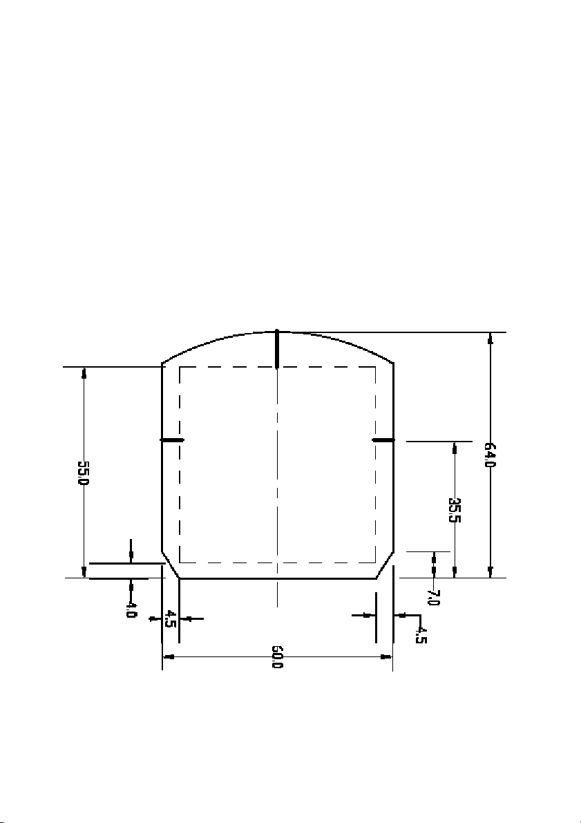
5.1.1 Message format
Create your own commercial message with the following outline format,
use thicker paper
Scantech-ID VEGA Area Imager 25
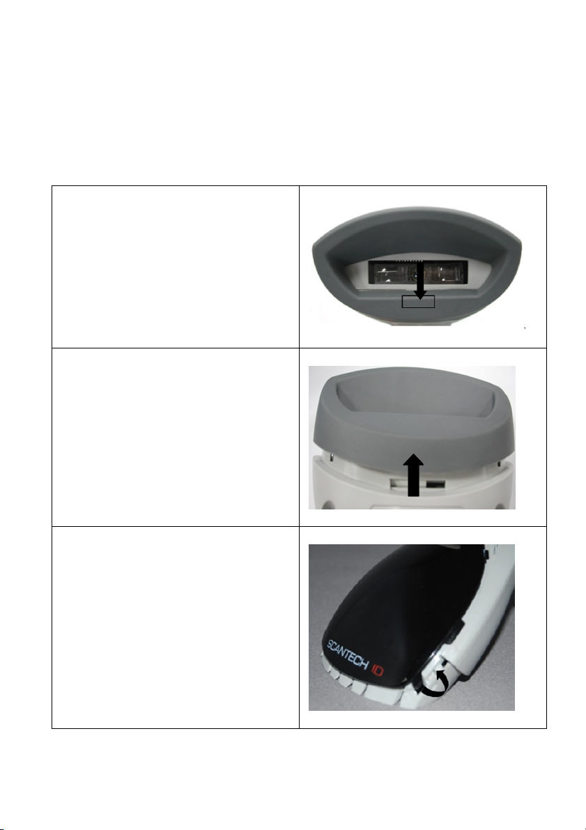
5.1.1 Change Cover Display
Follow the next instruction steps to change the black Cover Display into the
transparent Cover Display, so that your customers can read your own commercial
massage.
Step 1:
Press out the front rubber lid toward
the arrow
Step 2:
Pull out the front rubber lid off the main
unit
Step 3:
Press out top cover rim from the inner
lock
26 Cover Display
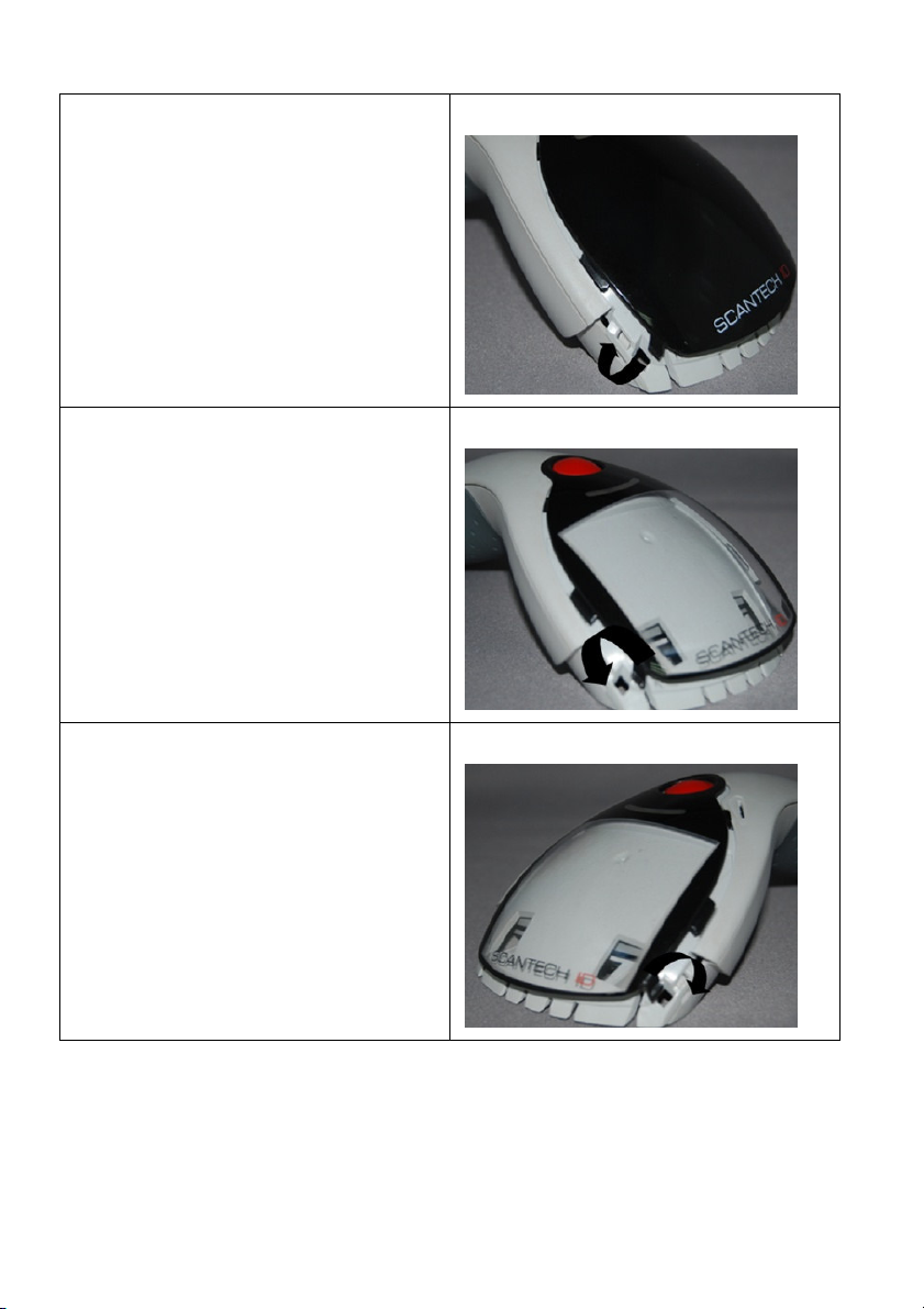
Step 4:
Press out the other side of inner lock
and remove the complete cover
Step 5
Assemble transparent top cover rim
into inner lock.
Step 6
Assemble another side transparent top
cover rim into the inner lock
 Loading...