

Scanstrut PT2001,PT2002,PT2003,PT2004,PT2005,PT2006 Installation Instructions Manual

www.busse-yachtshop.de | info@busse-yachtshop.de
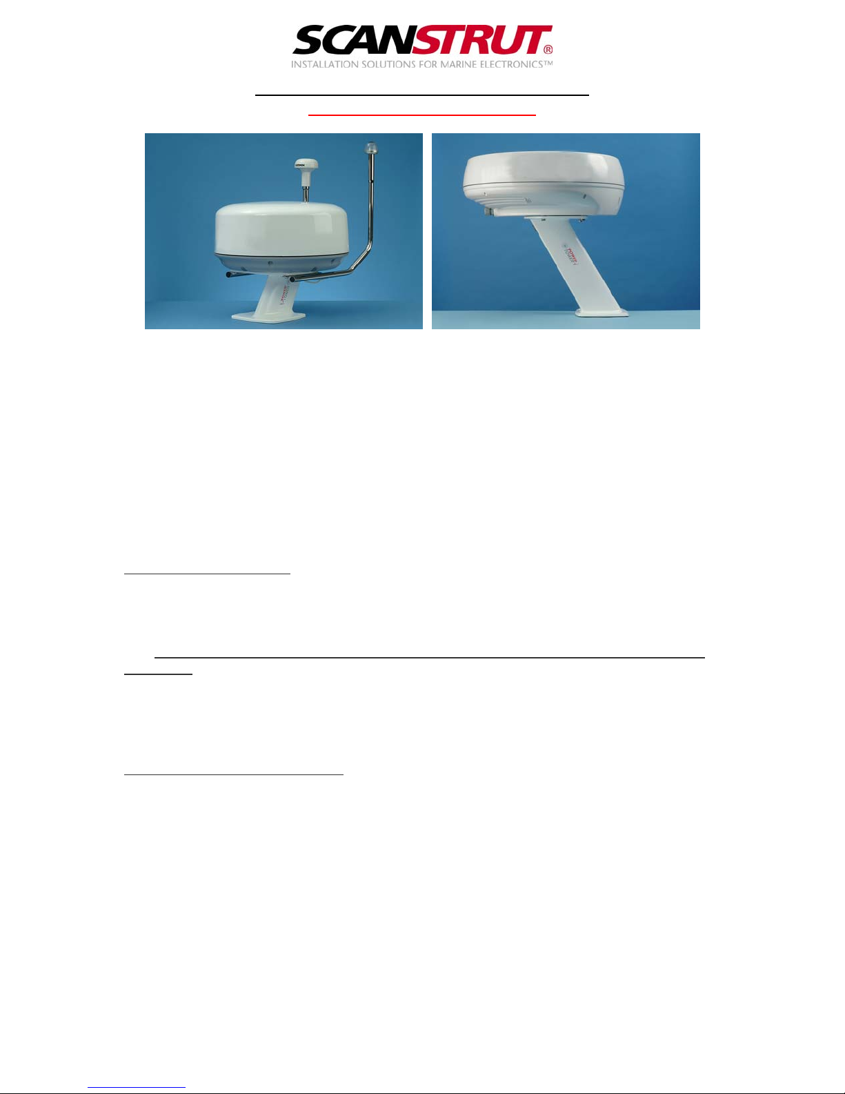
Composite PowerTower Installation Instructions
PT2001 / PT2004 Page 2
PT2002 / PT2003 / PT2005 / PT2006 Page 3
Scanstrut Ltd. 1 Malt Mill, Totnes, Devon, UK TQ9 5NH Tel: +44(0)1803 863800 Fax: +44(0)1803 862223
e-mail: technical@scanstrut.com website: www.scanstrut.com
www.busse-yachtshop.de | info@busse-yachtshop.de
Composite PowerTower - PT2001/4
Installation Instructions
PowerTower kit contents
• PowerTower
• Base Seal
• 4 x Nylon Shouldered Washers
• IP67 Cable Grommet
Also Required:
• 4 x M8 Stainless Steel bolts, large washers and nuts to attach PowerTower to
deck/arch. Length to suit deck/arch thickness.
• Ø8.5mm Drill.
• Hole Cutter for cable loom; approx Ø50mm dia.
Drilling for the antenna.
1. Attach the PowerTower antenna template to the top of the top plate of
PowerTower. Mark through the centre of the holes for the antenna you are to mount.
IMPORTANT:
[A] Check that the doles shown on the drilling template match that of your
antenna.
2. Drill a pilot hole (about 2mm dia.) through the top of PowerTower.
3. Turn over PowerTower and, from the underneath of the top plate; open out the
holes to the required diameter.
Fitting PowerTower to the boat.
1. Attach PowerTower to the boat using 8mm (5/16 in)
bolts, nuts and washers. Selflocking or Nyloc nuts are recommended. Fit the white seal under the base of the
PowerTower.
2. Attach the antenna to the top of PowerTower using the bolts provided with the
antenna.
3. Install the cable using the waterproof grommet supplied. To fit the cable: Push
cable through hole in grommet to its chosen point and pull back until the internal
part of the grommet reverses back.
Scanstrut Ltd. 1 Malt Mill, Totnes, Devon, UK TQ9 5NH Tel: +44(0)1803 863800 Fax: +44(0)1803 862223
e-mail: technical@scanstrut.com website: www.scanstrut.com
 Loading...