

Page 1
USER’S MANUAL
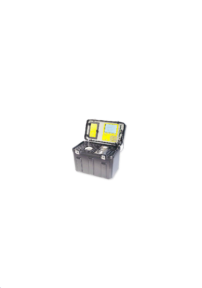
TC2000
PORTABLE TEMPERATURE
CALIBRATOR
A universal stable and accurate temperature well for
calibrating
and verifying temperature sensors
Manual revisjon: June, 2002
Copyrighted © 2002
Page 1
Page 2

TC2000 user’s manual
Thank you
for purchasing a Tek Know temperature calibrator.
The Tek Know products are manufactured by Scan-Sense AS in
accordance with our high quality standards in design, choice of
components and workmanship in order to achieve maximum customer
satisfaction and to full our vision to be our customers “First Choice”.
The TC2000 is designed and manufactured by:
Scan-Sense AS Tel: + 47 33 36 30 00
Bekkeveien 163 Fax: + 47 33 36 31 80
N-3173 Vear www.scansense.no
NORWAY post@scansense.no
Scan-Sense AS reserves the right to make improvments or alterations
to our products without incurring any responsibility to make the same
improvments or alterations to products previously sold.
SCAN-SENSE AS
All rights reserved. No part of this publication may be reproduced, stored in a retrieval
system, or transmitted in any form by any means, electronic, mechanical, photocopying,
recording, or otherwise without the prior permission of Scan-Sense AS.
All efforts have been made to ensure the accuracy of this handbook. We at Scan-Sense
are always striving to improve our products and handbooks, therefore we would greatly
appreciate being informed of any errors found in our product or in its manual. The above
notwithstanding, Scan-Sense can assume no responsibility for any errors in this
handbook or of their consequenses.
Page 2
Page 3

TC2000 user’s manual
Contents
1 Introduction ...................................................................................................... 5
1.1 Certication ..................................................................................................... 5
1.2 Warranty ......................................................................................................... 5
1.3 Conventions used in this document ................................................................. 5
1.4 Introduction to dry-block calibrators ................................................................. 7
2 Preparation ...................................................................................................... 8
2.1 Unpacking and inspection ............................................................................... 8
2.2 Items supplied with the unti ............................................................................. 8
2.3 Input power connection ................................................................................. 10
3 Getting started ............................................................................................... 11
3.1 Operation controls and connections .............................................................. 11
3.1.1 Software Startup ........................................................................................... 12
3.1.2 LCD display ................................................................................................... 13
3.1.3 Well and insert ............................................................................................... 13
3.1.4 Numerickeypad................................................................................................14
3.1.5 Power on / off ................................................................................................. 14
3.1.6 RS232 Communicatiion ................................................................................. 14
3.1.7 Sensor connection ......................................................................................... 14
3.2 Sensor positioning, connection and calibration accuracy .............................. 15
3.3 Procedure to run calibration .......................................................................... 16
3.4 Procedure to run a liquid bath calibration ...................................................... 17
3.4.1 Calibrating a thermostat .................................................................................18
3.4.2 Calibrating a sensor .....................................................................................18
3.5 Finish the calibration ..................................................................................... 21
3.6 Defaults values .............................................................................................. 22
3.7 Pre-calibration cleaning of well and insert ..................................................... 23
3.7.1 Procedure for cleaning the interior of the temperature well and insert .......... 23
3.7.2 Procedure for cleaning the exterior of the insert ............................................ 24
3.7.3 Instructions for handling Liquid-lled Insert ................................................... 24
4 Operational menus, controls and indicators .................................................. 25
4.1 Introduction .................................................................................................... 25
4.2 Main Menu ..................................................................................................... 25
4.3 Manual Calibration ........................................................................................ 26
4.4 Conguration ................................................................................................. 27
4.4.1 Reference seonsor selection ......................................................................... 27
4.4.2 Reference sensor conguration ................................................................... 27
4.4.3 Reference correction ..................................................................................... 28
4.4.4 Test sensor .................................................................................................... 30
Page 3
Page 4

TC2000 user’s manual
4.5 System information ........................................................................................32
4.6 Settings ..........................................................................................................32
4.7 Automatic calibration ......................................................................................33
4.8 Semi automatic calibration .............................................................................35
4.9 Calibration report ........................................................................................... 37
4.10 Software upgrade utility ..................................................................................38
5 Technical tips ................................................................................................. 39
5.1 General information regarding accurate dry-block calibrations ..................... 39
5.2 The importance of testing instrument validation ............................................ 40
5.3 The importance of a traceable standard ........................................................ 40
5.4 Correct positioning of the probe in the temperature block ............................. 40
5.5 Calibrating a short-stem probe .......................................................................41
5.6 Using the calibrator as a reference when adjusting measuring devices
(meters/gauges) ............................................................................................ 42
5.7 The Time Constant inuence on temperature-well mass ............................... 42
5.8 When to take the calibration reading ............................................................. 42
5.9 The importance of cleanliness to attain high accuracy results ...................... 43
5.10 Insulating with glass wool to minimize cold/heat loss to surrounding air ....... 43
6 Specications ................................................................................................ 44
7 Electrical specications ................................................................................. 44
Page 4
Page 5

TC2000 user’s manual
1 Introduction
1.1 Cerication
Scan-Sense AS certies that the TC2000 complies with its published
list of specications at the time it was manufactured. Scan-Sense AS
also certies that its calibration measurements are traceable to
Norwegian Accreditation and to the calibration facilities of other
International Standards Organization (ISO) members. Scan-Sense AS
conrms that the TC2000 complies with the following standards:
EMC EN61326-1:1997+A1:1998: APP.A, immunity
test requirements for equipment intended for use in
industrial locations, as amended by EC Directive 9
2/31/Eec and the European Low Voltage Directive IEC
61010-1:90 + A1:92 + A2:95, amended by 93/68/EEC.
To ensure compliance, please use screened/shielded
serial communication leads (RS232).
1.2 Warranty
This product is guaranteed free from defects in material and
workmanship for one (1) year from the date of shipment. During this
warranty period, Scan-Sense AS will, as its option, either repair or
replace the TC2000 should it prove defective. The product must
be returned to a service facility designated by Scan-sense AS
for warranty service or repair (see our worldwide adress le http://
www.scansense.no). The foregoing warranty will not apply to defects
resulting from improper or inadequate maintenance by the purchaser,
purchaser-supplied software or interfacing, unauthorized modication
or misuse, operation exceeding the environmental specications for
the TC2000, or improper site preparation or maintenance. No other
warranty is expressed or implied by Scan-Sense AS, and Scan-Sense
AS shall not be liable for any direct, indirect, special, incidental or
consequential damages, whether based on contract, tort, or any other
legal theory.
1.3 Conventions used in this document
We have provided this section of the User’s Manual to help you
identify noteworthy symbols, terms and conventions used in this
manual. Look for the following:
Page 5
Page 6
TC2000 user’s manual
CAUTION:
Is used when a procedure may cause damage to equipment
or affect operation
WARNING:
Is used when a procedure may cause personal injury to the
reader or other persons
A SYMBOL USED AS A WARNING
TO DENOTE A HAZARD
CONFORMITÉ EUROPÉENNE
GROUND OR EARTH
Terms and denitions:
The term “insert” is interchangable with “insert adapter” as an
equipment identier for the 2-inch diameter, 6-inch long aluminum
insert pleced into the temperature well.
We dene calibration as being able to compare the ability of the
equipment to perform to a known standard. Temperature calibration
provides a means of quantifying uncertainties in temperature
measurement in order to optimize sensor and/or system accuracy.
LCD is a term meaning a quarter (1/4) VGA LCD screen.
CARE is a memory jogger to ensure best results and safe use of
the equipment.
Connect only to the correct power voltage/frequency (read the label
in the case).
Always clean the temperature well and insert before use, and always
remove the insert from the temperature well before moving or tran sporting the TC2000.
Replace worm connection cables (only with approved connection
cables).
Earthed (or grounded) power sources only should be used.
Page 6
Page 7
1.4 Introduction to dry-block calibrators
Dry-block calibration units provide the reliable heat (or cold)
source needed to verify the accuracy of industrial sensors such as
RTDs, thermocouples, thermostats, bi-metal thermometers or liquid in-glass thermostats. The TC2000 is designed to provide all the
advantages offered by “dry well” temperature calibrators: Convenience
of size, weight, speed, portability temperature range, stability and
software interaction via RS232 communication port. It is also designed
to be “user friendly”.
The TC2000 has a numeric keypad, or softkey controls, for setting
the well temperature. Menus are used to dene other data for the
TC2000. The display shows the dened “Set temperature”
and the resulting “Reference temperature” for the well temperature.
Connection points at Channel A and B allow a variety of sensor hook ups and an RS232 connection for local PC or remote computer.
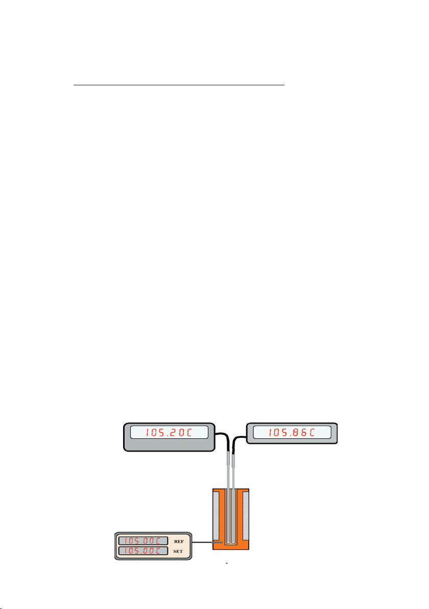
The dry well in the calibrator is heat or cold source, and a reference
thermometer. That is, the thermometer (or sensor to be tested)
is placed in the well and its reading is compared to the reading of the
temperature in the calibrator’s display. The calibrator’s display shows
both the dened temperature, as set by the operator, and the actual
temperature that is measured by the internal reference sensor in the
well.
Figure 1: Dryblockschematics
EXTERNAL REF.
CALIBRATOR DISPLAY
INTERNAL REF.
SENSOR TO BE TESTED
PELTIER ELEMENTS
HEATING BLOCK
COMPARISON
Page 7
Page 8

TC2000 user’s manual
2 Preparation
2.1 Unpacking and inspection
* Inspect the packing container for any sign of damage. If the shipping
cartong is damaged, contact the carrier/shipper.
* Remove the unit from its packing container and inspect it for visible
signs of damage.
* Check that the equipment received matches the inventory. Report
ny discrepancies to Scan-Sense AS’s designated agent.
* Record any discrepancies from the inventory and/or visible damage
to the unit; see Figure 3 TC2000 orientation and location of items.
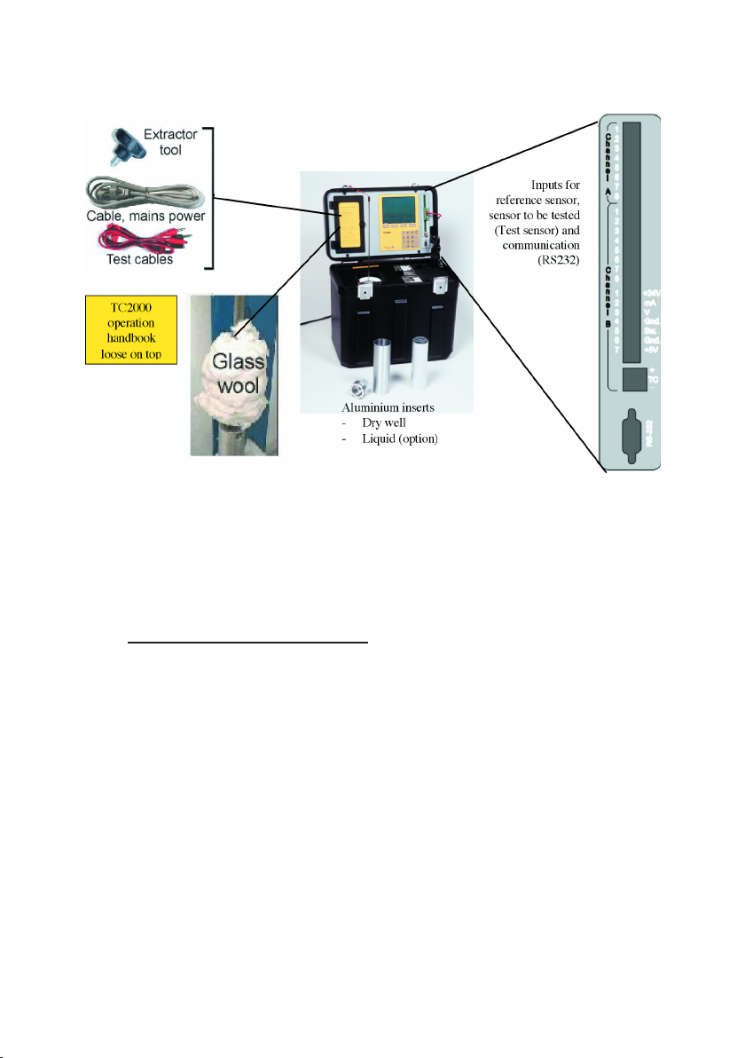
2.2 Items supplied with the unit
The cables, insert etc. that are used with the TC2000 are located in
compartments within the unit. The TC2000 Parts List identies each
by part name and part number.
TC2000 PARTS LIST
DESCRIPTION OF ITEM: (1 OF EACH ITEM)
* GLASS WOOL, 1 PACK
* TOOL, EXTRACTOR
* CABLE, MAINSPOWER, 100 VAC
DETERMINE TYPE REQUIRED, JAPAN
* CABLE, MAINSPOWER, 110 VAC
DETERMINE TYPE REQUIRED, USA
* CABLE, MAINSPOWER, 230 VAC
DETERMINE TYPE REQUIRED, EUR
* CABLE, MAINSPOWER, 230 VAC,
DETERMINE TYPE REQUIRED, UK
* CABLE, TEST, 1 SET
* USER’S MANUAL
* CALIBRATION CERTIFICATE
* RS232 CABLE
* CONNECTOR KIT
Page 8
Page 9
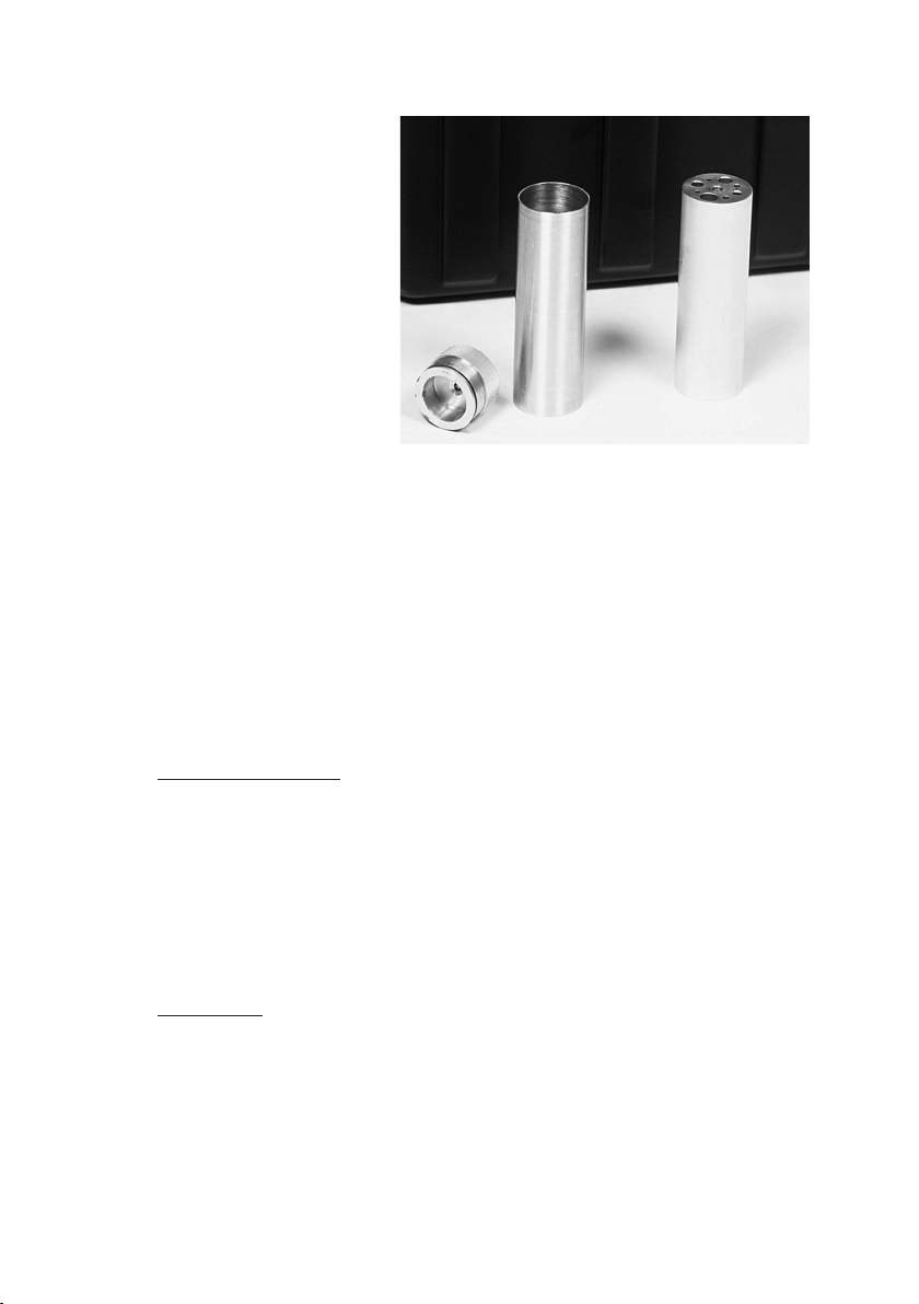
Aluminum inserts
- Dry Well
- Liquid lled (option)
Insert, aluminum, of 2“ x 6” or 50 mm x 150 mm diameter
and lenght with:
2 holes of 6.5 mm bore,
2 holes of 3,5 mm bore,
2 holes of 4,5 mm bore,
1 hole of 8 mm bore,
1 hole of 10 mm bore and
1 hole of 12 mm bore.
OPTIONAL ITEMS
Liquid-lled Insert, aluminium, of 2” x 6” or 50 mm x 150 mm
diameter and lenght with pop-off cap and impeller at bottom.
Insert, aluminum, blank of 2” x 6” or 50 mm x 150 mm ‘
diameter and lenght.
Oil to use with the Liquid-lled Insert.
CAUTION:
Care should be taken to avoid spillover into the temperature
well when using Liquid-lled Inserts. Use only recommended
oil/ liquids to ll the insert. Do not use glass wool with the
Liquid-lled Insert.
Page 9
Page 10
TC2000 user’s manual
Figure 3. TC2000 Orientation and location of items.
2.3 Input power connection
The required power is either 110 VAC or 230 VAC, 50/60 Hz. Always
connect the power cable supplied with your unit to a grounded or
earthed power outlet.
Page 10
Page 11
3 Getting started
This section contains a description of the TC2000 operator control and
connection points to help you get started quickly. The section also
provides instructions for pre-calibration cleaning of the well and
inserts (essential to the process) and step-by-step guidance for
performing a calibration.
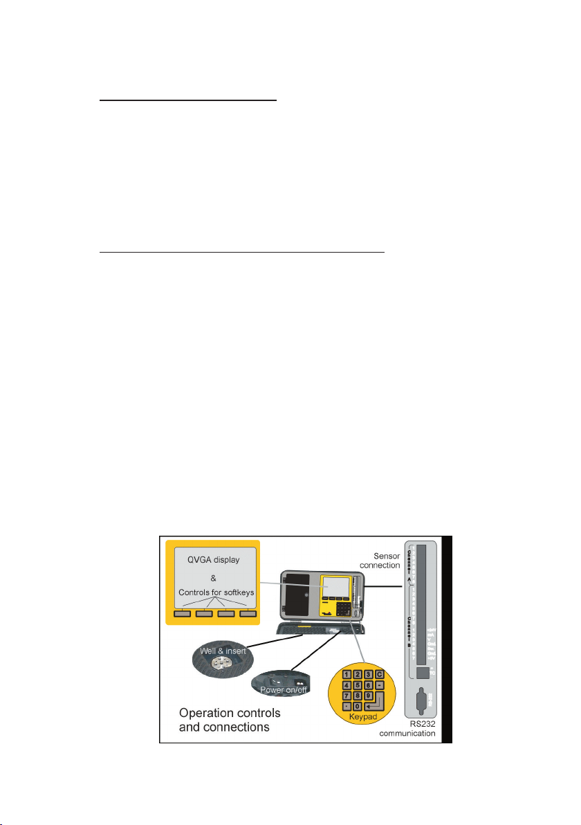
3.1 Operation controls and connections
Very little operator interaction is required to begin calibration. The main
operator interaction is via unit’s softkeys (or keypad) and LCD display,
or via a (local) PC or other remote computer. Communication with
the PC is via the unit’s RS232 serial port connector. To begin a
calibration, you must:
* Fit the insert into the well.
* Place the sensor(s) into the well and use glass wool to insulate
the sensor.
* Power on the unit ON.
* Connect the sensor leads in Channel B.
* Congure the sensor to be tested.
* Set the temperature using the TC2000’s LCD display, softkeys or
numeric keypad.
Page 11
Page 12
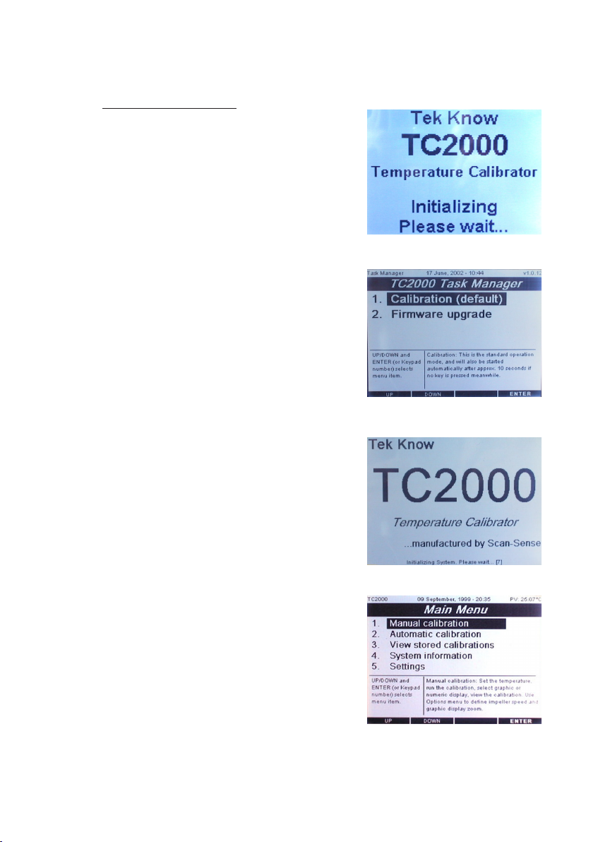
3.1.1 Software startup
When switching on the calibrator the rst
screen that is shown is a startup display
while the internal computer loads the
operating system Windows CE 2.12.
A Tast manager program will apear after
the CE 2.12 is loaded.
The task manager gives two choises
1. Calibration ( which is default) or
2. Firmware upgrade.
TC2000 user’s manual
start and will automatically be selected
after 10 sec. of the Task manager
appearing.
Choise 2. is used when a new software
or modication upgrade is to be entered
into the CE computer.
See seperate section for upgrade...
After choise 1. Calibration is selected
either by pressing enter when 1. is
highlighted or by default the computer
will load the TC2000 application software
This will take a couple of miniutes and the
status wil be shown at the lower part of
the screen viewing a countdown
proceedure. After loading is complete
the main menu screen will be displayed
and the calibrator is ready for calibration
tasks.
Choise 1. calibration is the normal
Page 12
Page 13
TC2000 user’s manual
3.1.2 LCD display
The menus and softkey-controls and information you need to dene
para-meters during a calibration are displyed in the unit’s
LCD (1/4VGA) display.
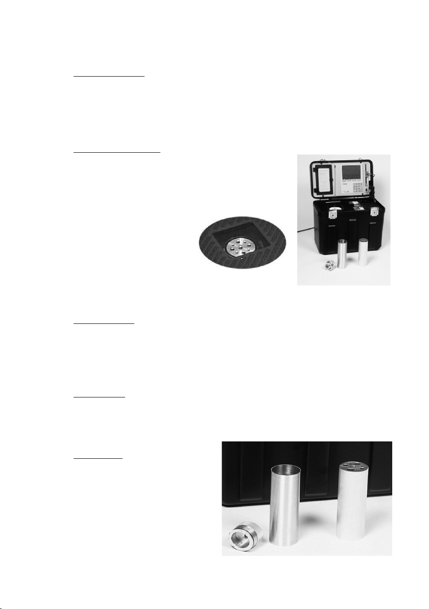
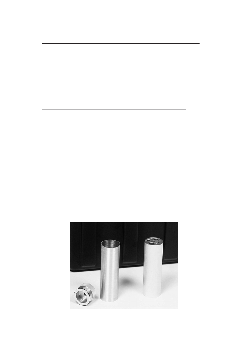
3.1.3 Well and insert
The well is an aluminum
block with a reference
sensor placed at its base.
The well heats or cools
to the temperature you
set. The insert has holes
bored to accommodate
most sensors.The insert
is aluminum and is
precision-turned to t the
well opening. An extractor
tool is provided to remove the insert from the well.
IMPORTANT:
The calibrator is calibrated with the external reference sensor
being insulated with supplied insulation material. to acheive
the same result use insulation round the sensor undergoing
test or calibration.
WARNING:
Handle carefully when extracting a Liquid-lled Insert because
the liquid in the insert will be hot and may cause burns to
any skin surfaces in contact with it.
CAUTION:
Care should be taken to avoid
spillover into the temperature
well when using Liquid lled
Inserts. Use only recommended
oil / liquids to ll the insert.
Do not use glass wool with
Liquid-lled Insert.
Page 13
Page 14
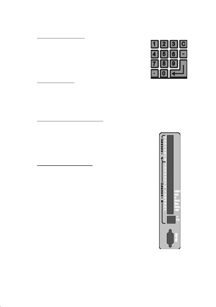
3.1.4 Numeric keypad
The numeric keypad is used for entering
data into the menus. It can also be used
instead of the UP or DOWN softkeys when
setting temperatures.
3.1.5 Power on/off
The power cable connection and the power
ON or OFF control is provided by a swich and-plug connector.
3.1.6 RS232 communication
The RS232 serial communication port is
used to connect the TC2000 to a PC during
re-calibration and for remote operation
when calibrating a sensor.
3.1.7 Sensor connection
Different types of sensors can be connected
for testing. Channel A is for the external
reference sensor. Channel B is for the
sensor under test (test sensor).
TC2000 user’s manual
Page 14
Page 15

TC2000 user’s manual
3.2 Sensor positioning, connection and calibration
accuracy
The calibrator well is always the source for heat or cold for the sensor.
However, it is possible to connect the sensor such that the calibrator
is the reference and the temperature reading is shown at the QVGA
display, or the sensor can be connected to an external measurement
device for the readnig.
You must place the sensor and the reference sensor as close to each
other as possible to ensure an accurant reading, regardless of what
reference and connections you use. To make the calculation accurate
when the sensors are placed at some distance from each other; you
can use a previously determined offset value to dene the correction
factor you need to adjust for the difference-in-distance between
sensors.
Note:
Note:
External ref.
External ref.
Note:
at same level
at same level
External ref.
at same level
Page 15
Page 16

TC2000 user’s manual
3.3 Procedure to run calibration
1. To obtain the best temperature transfer, clean the temperature well
and insert before each use. Instructions are provided in section 3.7.
2. Select the insert to be used and lower it into the temperature well.
3. Lower the temperature sensor into the insert. Use glass wool if it is
necessary to close off the top of the insert to prevent heat or cold
loss. (Glass wool is not to be used in liquid inserts).
4. Power ON the TC2000. The opening menu will appear. If necessary,
refere to the chapter 4 Operation menus, controls and indicators.
5. Connect the temperature sensor to your indicating instrument.
6. Select 2 Conguration to select the type of sensor to be tested.
7. On the Conguration menu, select 4. Test Sensor.
8. On the Conguration menu, select the CONFIG softkey to obtain
wiring information for Channel B.
9. If you are using an external reference sensor, select 2. Reference
sensor.
10. Select the CONFIG softkey to obtain wiring information for Channel A
(refernse sensor).
11. If you are using sensor-correction values, select 3. Sensor
correction and Table.
12. Select the CONFIG softkey to dene the Read value, True value and
tag identier in the table.
13. The default temperature setpoint is 25º Celcius (C). If you
want the temperature denored in F or K, see the Settings menu.
14. Press the MAIN MENU softkey to exit the Conguration menu and
save the new data.
15. Select 1. Calibration mode and use the UP or DOWN softkeys to
dene the temperature.
Page 16
Page 17

TC2000 user’s manual
3.4 Procedure to run a liquid bath calibration
1. Follow 1-15 in chapter 3.3
2. Choose the right liquid for the temperature range:
Water: 0 °C to 98ºC
Oil : 40 °C to 150ºC
NOTE:
Insulation pad has to be used at the top of the insert
during the calibration.
WARNING:
Use eye protection if you are using oil or water above
70ºC to avoide eye injury caused by splashing oil or water
bubbles.
WARNÌNG:
Be sure that you are using oil (liquid) which is approved for
the temperature range that you are working at.
3. Select 1. Calibration mode to select the Impeller speed.
4. On the Calibration menu, select OPTIONS and use the
numeric keys to set the impeller speed in %.
5. Impeller speed:
In order to get the best circulation in the liquid and thereby
avoiding gradients, it’s of great importance to select the
correct impeller speed. For example circulated water at too
high speed will produce air bubbles and turbulence, which
could lead to gradients in the liquid.
Gradients may also occur if the circulation is too low. The
amount of sensors to be tested at the same time in the liquid
insert will also have a signicant impact on the circulation.
As a general rule start with the following values if you are
testing a single sensor:
Water: 15% and up depending on amount of sensors.
Viscosity in the range 0 to 98ºC is almost the same.
Oil: 50% and up depending on amount of sensors and
temperature range since the viscosity changes a lot
over the range - 40 to 150ºC.
Page 17
Page 18

TC2000 user’s manual
6. TIPS! You will get an extreme stability (typically +/- 0.001ºC)
and accuracy as a stirred ice bath (0ºC). Just set the impeller
speed to 100% and set point to -3ºC and wait for the freezing
point to come.
3.4.1 Calibrating a thermostat:
Use the test cables to connect the thermostat to Channel B according
to the wiring information provided in the unit’s QVGA display. Use the
UP or DOWN softkeys to dene the temperature, then watch for the
display indicator to show if the switch is closed or open.
3.4.2 Calibrating a sensor:
Use the numeric keypad or UP or DOWN softkeys to dene the
temperature. The displayed Reference sensor temperature (the
temperature measured at the center of the temperature well) will
increase to the set value. When the Reference sensor temperature
has been stable at +/- 0.2ºC for at least 17 minutes (default), a * will
appear in the display to indicate that you can take the reading.
If you require a new setting:
Change the tempterature to the new value and wait for the * in the
display to indicate that you can take the reading.
Calibration mode graphical:
Page 18
Page 19

Page 19
Page 20

TC2000 user’s manual
Page 20
Page 21

Calibration mode numerial:
3.5 Finishing the calibration
7. When nished, adjust temperature to ambient and allow the
temperature well to cool to temperature below 70ºC.
8. Pull the temperature sensor(s) out of the insert.
9. Attach the extractor tool to the insert and pull the insert out of the
temperature well.
10. Switch power OFF.
11. Allow the unit to attain temperature below 70ºC before stowing
accessories.
Page 21
Page 22
TC2000 user’s manual
3.6 Defaults values
It is possible to change some of the parameter values displayed in
the menus.
Default set temperature = 25ºC (not changeable)
Default temperatre units = °C
Default reference sensor = Internal sensor
(located in the TC2000 well)
Default stabilization time = 17 minutes
Default stabilization ∆ T = ±0.2°C
Information is given in chapter’s 4.4 , 4.5 and 4.6 on how to alter
some of these parameters.
The following data is dened during manufacturing and cannot be cannot be changed
during its operation.
Serial number TC2000 Well Firmw.version TC2000 Well
Serial number TC2000 SIM Firmw.version TC2000 SIM
.
On completion of a calibration, the TCCal software will add the following data:
Calibration date TC2000 Well Next calibration date TC2000 Well
Calibration date TC2000 SIM Next calibration date TC2000 SIM
Page 22
Page 23

3.7 Pre-calibration cleaning of well and insert
If necessary, clean the temperature well (interior) and insert
(interior and exterior) before use. A dirty or oxidized surface can
affect the transfer of heat between the well and the insert and may
also cause the insert to stick in the well and be difcult
to remove.
WARNING:
Use eye protection if you are using compressed air to blow
debris out of the temperature well or insert openings to avoid
eye injury.
3.7.1 Procedure for cleaning the interior of the temperature
well and insert
1. Insert dry, white paper and turn it so as to remove all dust, dirt or
smudges from the interior of the temperature well to ensure optimal
heat trensfer to the temperature sensor.
2. If necessary, use compressed air to blow debris from the interior of
the temperature well and insert. (A small vacuum hose can be used
to extract debris).
3. If necessary, use a cloth with mild soap and water to remove
exessive contamination. Alcohol may also be used for this purpose.
4. Use a rod with a small piece of cloth attached to it (e.g. gun cleaning kit).
5. When using liquid cleaners, ensure that the well, insert and probe
is completely dry before placing the insert to the well.
Page 23
Page 24
TC2000 user’s manual
3.7.2 Procedure for cleaning the exterior of the insert
1. Insert dry, white paper and rub so as to remowe all dust, dirt or
smudges from the exterior surface of the insert to ensure optimal
heat or cold transfer from the temperature well.
2. Wipe clean with a clean, dry, lint-free cloth.
3.7.3 Instructions for handling Liquid-lled Insert
Only use clean oil, water or other liquids that have been authorized
for use in the Liquid-lled Insert.
CAUTION:
Care should be taken to avoid spillover into the temperature
well when using Liqued-lled Inserts. Use only recommended
oil/liquids to ll the insert. Do not use glass wool when using
Liquid-lled Inserts.
WARNING:
Handle carefully when extracting a Liqued-lled Insert
because the liquid in the insert will be hot and cause burns
to any skin surfaces in contact with it.
Page 24
Page 25

4 Operational menus, controls and
indicators
4.1 Introduction
The TC2000 is highly automated and requires minimal operator
interaction during a calibration. Normally, you are only required to set
the temperature necessary for the calibration and to congure the
sensor to be tested.
4.2 Main Menu
The Main Menu contains sub-menus to main available functions.
Menu entries are listed with a unique number. To select Main Menu
functions:
Press the UP or DOWN softkey,
and then press the ENTER softkey,
or
Select the function-number on
the numeric keypad (Do not press
ENTER when using a number from
the numeric keypad).
The selected menu line is inverted
The VGA LCD display will show Information regarding interaction,
controls and the available menus.
NOTE:
The TC2000 uses the dened conguration values until they are
changed. Therefor, it is important to ensure that the values are cor rectly dened before starting a calibration.
When power is swiched on, default opening screens will show until the
calibrator has booted and the main menu screen in visible.
Page 25
Page 26

TC2000 user’s manual
4.3 Manual Calibration
Select choice 1. Manual calibration,
to enter the manual calibration mode,
the Conguration menu will then be
displayed. This will enable you to
congure your reference sensor and
the type of sensor to be tested.
See chapter on Conguration for more
details on how to congure and select a
sensor.
Press Continue to enter into the manual
calibration mode.
The set point temperature can either be
set using the numerical keypad + enter
or using the softkeys. The softkeys will
give setpoint increments of 10°C
Pressing the MAIN MENU softkey will
take you back to the main menu.
Selecting the OPTIONS softkey in the
manual calibration mode will allow you to:
* Set the temperature resolution in the
graphical display using the ZOOM IN
and ZOOM OUT softkeys
* Toggle between the graphic and the
numeric displays.
* Dene the speed of the liquid insert
impeller in % of full speed
( 0 to 100 % in steps of 1 ).
Default values are:
* Set temperature = 25 ºC
* Swich test = OPEN
* Impeller speed = OFF (0%)
* Graphical resolution = 2 °C / horizontal line
Page 26
Page 27

4.4 Conguration
Important input connection information
to remember:
Channel A is the connector for the
external “Reference sensor”.
Channel B is the connector for the
sensor to be tested “Test sensor”.
4.4.1 Reference sensor selection
The NEXT softkey will allow you to
navigate and change each setting by
stepping up or down in the menu.
Use the SELECT softkey to select
the available settings.
Select 1. Internal, to use the calibrators
internal reference sensor. In the manual
calibration mode window the reference
sensor will be labeled with Internal.
Select 1. Pt100, to use an external
reference sensor.
Then press CONFIG to setup the
external reference sensor.
4.4.2 Reference sensor conguration
The external reference sensor can be
congured as either a 2, 3 or 4 wire
sensor. Use the UP and Down softkeys
to select the appropriate conguration.
Please note that in each conguration
the sensor will be terminated differently
to the 8-pin connector.
See advisory text giving pin connections.
Page 27
Page 28
TC2000 user’s manual
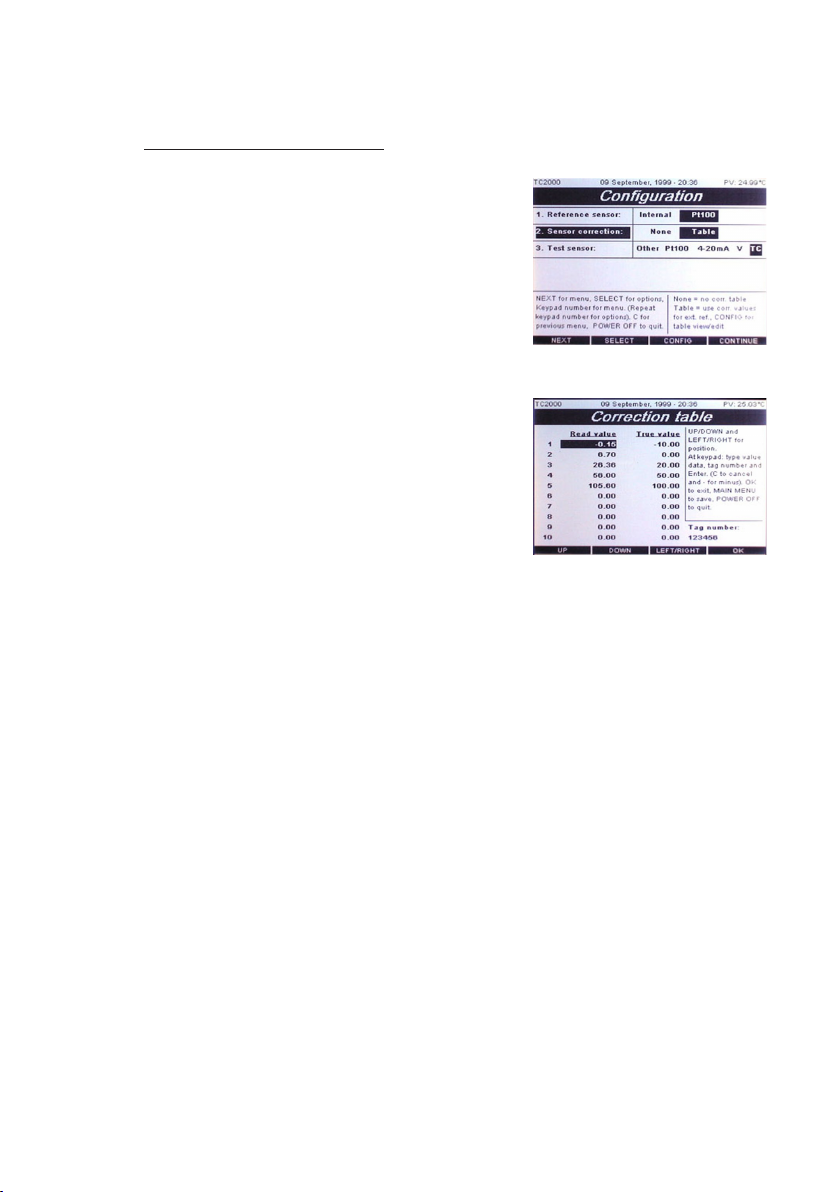
4.4.3 Reference correction
If you have selected an external sensor
as the reference sensor, its correction
values can be placed into the sensor
correction table. Sensor correction
will show the value as None
(internal sensor or no correction data),
and Table (sensor correction data).
The default selection is None.
Reference sensors that have calibration
data values which have been determined
during a calibration, can be placed in a
table to allow correction of the reference
sensor so that the result will be that the
reference sensor works in true
temperature.
1. Use NEXT softkey to move to 2. Sensor correction. The selected
“cell“ 2. Sensor correction will be inverted.
2. Press SELECT softkey to change your options.
3. Press the CONFIG softkey and use the UP or DOWN and
LEFT/RIGHT softkeys to dene the correction information and
tag number for the Pt100. Press EXIT when nished. The
correction values that are placed in the correction table are
normally produced during calibration of the sensor. For example,
when a sensor reads 21.0 temperature (Read value), the display
shows the correct value as 20.0 (True value). Read value is what
the sensor is reading, True value is what it should be reading.
4. Press EXIT to return to the 3. Sensor correction menu.
5. Move to another item in the menu by pressing NEXT, or press
MAIN MENU to save your changes.
When the Sensor correction table for the Pt100 is selected, it will
Page 28
Page 29

always be used whenever the Pt100 is dened as the reference
sensor for this conguration , until you change the conguration.
NOTE: It is very important to remember which reference sensor is
being used, and whether or not you need to use
the sensor correction table. If you are using the internal
temperature reference, return to 2. Reference sensor,
select INTERNAL and OK.
Page 29
Page 30
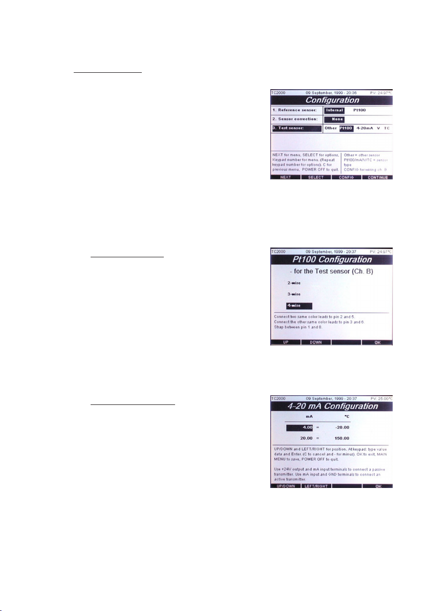
4.4.4 Test sensor
You can use 3. Test sensor: to select the
type of sensor to be tested and to obtain
information for connecting it to Channel B.
The default selection is Pt100.
To make a selection:
Use the NEXT softkey to move to
3. Test sensor: The selected “cell”
3. Test sensor is inverted.
Press SELECT softkey to change your
options.
1. Pt100 selection : Select Pt100 using
SELECT softkey and press CONFIG
softkey to obtain Channel B connection
information.
In CONFIG, use the UP or DOWN
softkeys to select the wiring for
obtaining the connection information
for the Pt100. Press the OK softkey
when nished. Then press CONTINUE
softkey in Conguration to start
manual calibration.
TC2000 user’s manual
2. 4-20 mA selection : Select 4-20mA
using SELECT softkey and press
CONFIG softkey to obtain Channel B
connection information.
In CONFIG, use the UP or DOWN
softkeys to dene the miliamphere
to temperature information from the
4-20 mA sensor, and the wiring
connection information for the 4-20 mA.
Press OK when nished. Then press
CONTINUE softkey in Conguration
to start manual calibration.
Page 30
Page 31

3. Volt selection : Select V using
SELECT softkey and press CONFIG
softkey to obtain Channel B connection
information connection information.
In CONFIG, use the UP or DOWN
softkeys to dene the voltage to
temperature information from the Volt
sensor, and the wiring connection
information for the Voltage snesor.
Press OK when nished.
4. Thermocouple selection : Select TC
using SELECT softkey and press
CONFIG softkey to obtain Channel B
Thermocouple Conguration
In Thermocouple Conguration
select the type of thermocouple using
the UP or DOWN softkeys.Press OK
softkey when nished .
5. Other sensor selection : Select OTHER using SELECT softkey
then press CONTINUE softkey to start the maual calibration
mode without using any of the inputs on channel B.
Other selection is used when the test sensor is connected to
external instrumentation.
Page 31
Page 32

TC2000 user’s manual
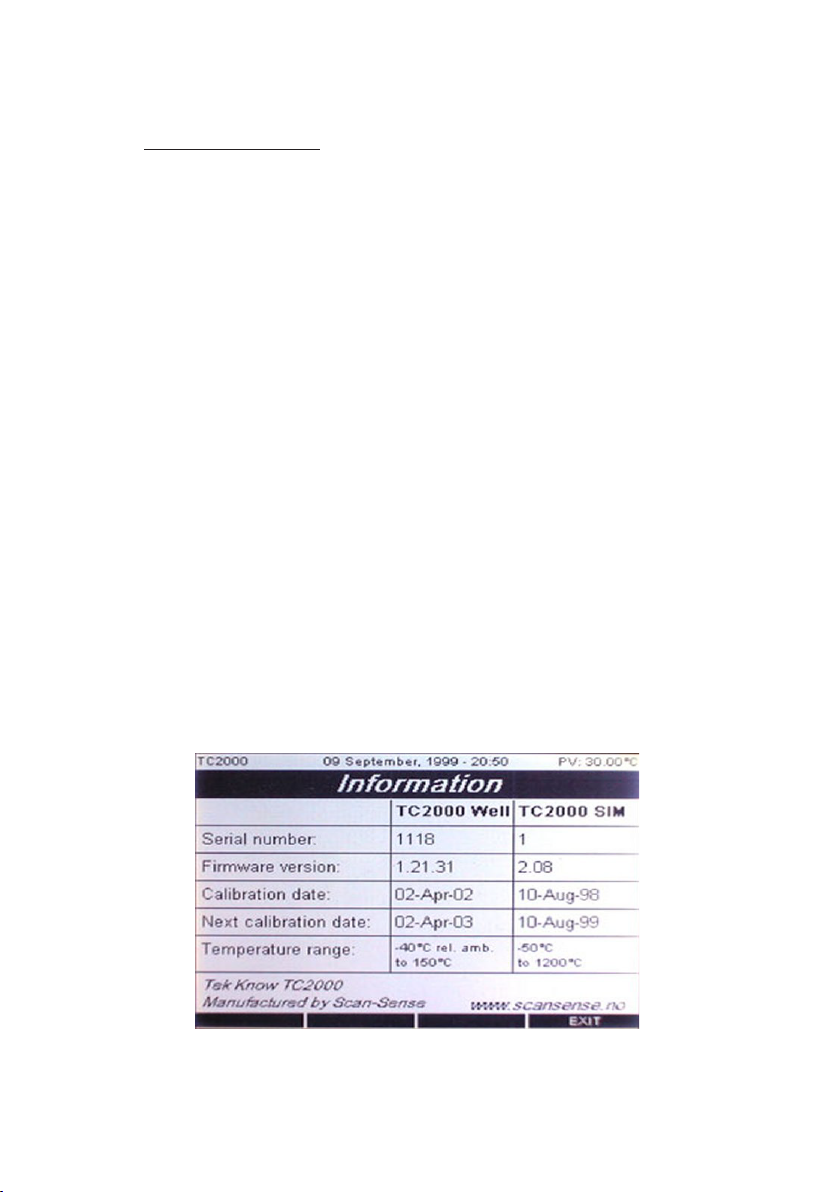
4.5 System information
The TC2000 contains the
following data that you cannot
alter during operation of the unit:
* Serial number TC2000 Well TC2000 SIM
* Firmware version TC2000 Well TC2000 SIM
* Calibiration date TC2000 Well TC2000 SIM
* Temperature range TC2000 Well TC2000 SIM
On completion of a re-calibration of TC2000, the TCCal
software will add the following data:
* Next calibration TC2000 Well TC2000 SIM
4.6 Settings
By highlighting either of the sections can
be set :
Temperature unit °C °F °K
Keypad beep ON OFF
Stabilization time 0 to 1hour
Stabilization span 0 to 20°C
Date and time
can be set
Page 32
Page 33

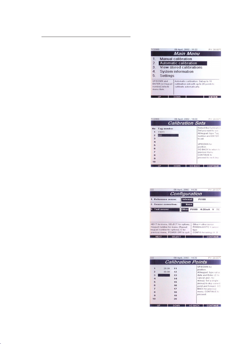
4.7 Automatic calibration
Select choice 2. Automatic calibration,
to enter the automatic calibration mode,
the Calibration Sets menu will then
be displayed. This will enable you to
set up your calibrator to perform an
automatic calibration task.
Each calibration set may consist of up to
20 calibration temperatures.
Up to 10 calibration sets may be
programmed. Each set is identied with a
tag number.
Press continue to enter the conguration
menu for your calibration set.
Select the conguration you want for your
calibration set.
See chapter 4.4 on sensor conguration.
Note the calibration set tag no. is
displayed in the top left corner of the
screen.
Press continue to enter
Calibration Points menu.
TC2000 user’s manual
Up to 20 different calibration point
temperatures can be set using the
numeric keypad.
The temperature range is from
-20°C to + 150°C
Press continue to start the automatic
calibration mode.
Page 33
Page 34

When the automatic calibration has
started the sensor temperatures will
be displayed in a graphical screen.
the calibration will continue automatically
through every set point temperature that
was set in the Calibration Set.
TC2000 user’s manual
one can dene to simulate at stable state
in order to force the TC2000 to make a
measurement and proceed to the next set
point temperature.
Pressing View List in the soft key menu
displays the calibration set points that
have alredy been performed.
After the last calibration set point
temperature has been completed the
Calibration nished menu will show.
In this menu there are options for
dumping the calibration data to a
computer or printing a calibration report
to a serial printer.
See section for serial port setup.
At any stage in the calibration process
Page 34
Page 35
4.8 Semi Automatic calibration
Select choice 2. Automatic calibration,
to enter the automatic calibration mode,
the Calibration Sets menu will then
be displayed. This will enable you to
set up your calibrator to perform an
automatic calibration task.
Each calibration set may consist of up to
20 calibration temperatures.
Up to 10 calibration sets may be
programmed. Each set is identied with a
tag number.
Press continue to enter the conguration
menu for your calibration set.
Select the conguration you want for your
reference sensor. See chapter 4.4
on sensor conguration.
For test sensor select Other to enter the
Semi Automatic Mode.
Press continue to enter
Calibration Points menu.
TC2000 user’s manual
Up to 20 different calibration point
temperatures can be set using the
numeric keypad.
The temperature range is from
-20°C to + 150°C
Page 35
Page 36

Press CONTINUE start the semi-automatic
calibration. The temperature of the well will be
shown on the LCD screen. At any time you may
choose to similate a stable condition of your test
sensor by selecting the SIM.STABLE softkey
option.
When the temperature and sensor is at a stable
state the calibrator will promt you for a
temperature entry of your test sensor. Enter this
using the numerical keypad on the TC2000. The
calibrator will then continue to the next set point
temperature.
TC2000 user’s manual
At any time during the semi-automatic calibration
the Calibration View menu can be activated
to show the progress in the calibration.
After the last set point temperature is stable and
a entry has been made the Calibration Finished
menu will be displaed.
from here you have the choise to dump the
calibration data to an other computer via RS232
or send a calibration report to a serial printer.
Page 36
Page 37

TC2000 user’s manual
4.9 Calibration report
T E M P E R A T U R E
C A L I B R A T I O N R E P O R T
Printing date: 23-Jan-02 14:51 Page 1 of 1
---------------------------------------------------------------------------------------------------------------------------------
Type of instrument : Temp node1
Model : Proto
Manufacturer : ScanSense AS
Serial number : 01
Tag/Id Number : 4
Temperature range : 0 -150 C
Output signal : 0-10 V
Accuracy : 0.5%
---------------------------------------------------------------------------------------------------------------------------------
No Set point Ref value Test value Deviation Date/time
1 28.00 C 28.00 C 29.24 C 1.24 C 9-Apr-02 14:02
2 30.00 C 30.00 C 31.06 C 1.06 C 9-Apr-02 14:19
---------------------------------------------------------------------------------------------------------------------------------
Type of instrument : Temperature Calibrator
Model : Tek Know TC2000 Sensor Interface Module : Input Ch.B OTHER
Manufacturer : Scan-Sense AS
Serial number : (SIM serial no.)
Temperature range : (i henhold til input valg)
Accuracy : (i henhold til input valg)
Calibration cert.no. :
---------------------------------------------------------------------------------------------------------------------------------
Sensor : TC2000 Internal Reference
Manufacturer : Scan-Sense AS
Serial number : 1072
Temperature range : +/- 0.18% F.S.
Calibration cert.no. :
---------------------------------------------------------------------------------------------------------------------------------
Air temperature : 22 C
Air humidity : 70 %
------- -------------------------------------------------------------------------------------------------------------------------
Date calibrated : 9-Jan-02 14:02
Company : ScanSense AS
INSTRUMENT (SENSOR) CALIBRATED
CALIBRATION POINTS
INTERMEDIATE INSTRUMENT
REFERENCE INSTRUMENT
CALIBRATION ENVIRONMENT
CALIBRATION STATUS
Calibrated by : Certied by :
Page 37
Page 38

4.10 Software upgrade utillity
In order to be able to upgrade the
application a program called TC2000
Upgrade Utillity must be run on a PC
and the TC20000 must be connected to
the PC through the serial port.
In the start up proceedure of the
calibrator select Firmware upgrade when
the Task manger appears on the screen.
This will set up the calibrator so that it
can receive a new application software
from the PC.
TC2000 user’s manual
The transfere time and staus will be
displayed on the PC TC2000 Upgrade
Utillity program.
Use a standard TC serial cable for
transfere.
After the transfere is complete the
calibrator will automatically install the
software internal and go to the
Main Menu.
Page 38
Page 39

TC2000 user’s manual
5 Technical tips
We dene “calibration” as being able to compare the ability of the
equipment to perform to a known standard. Temperature calibration
provides a means of quantifying uncertainties in temperature
measurement in order to optimize sensor and/or system accuracy.
This chapter provides general, informative information about dry-block
calibration and tips/hints to help you obtain accurate calibrations
with the TC2000 dry-block calibrator. Dry-block calibration is
recommended for calibrating industrial sensors such as RTD
(Resistive Temperature Device), thermocouples, thermistors, bi-metal
thermostats or liquid-in-glass thermometers, etc., because the dry block provides the reliable heat (or cold) source needed to verify the
accuracy of these devicec.
The dry-block calibrator offers a combination of accuracy, portability
and price for industrial calibration applications. Most dry-well
calibrators will produce a calibration accuracy of better than +/- 0.5ºC.
For comparison of sensors in a dry-well’s temperature block, hole-to hole uniformity is typically +/- 0.05ºC. These uncertainties are well
matched to the typical uncertainties of industrial temperature sensors.
5.1 General information regarding accurate dry-block
calibrations
The dry -block in the calibrator is often used as heat/cooling source
and a reference thermometer - i.e., the thermometer (or sensor to be
tested) is placed in the block and its reading is compared to the
reading of the temperature in the dry-block calibrator’s display. The
calibrator’s display shows both the dened temperature, as set by the
operator, and the actual temperature that is measured by the block’s
internal sensor. To ensure an accurat calibration, always observe the
following when using this type of calibration:
* Ensure the internal reference sensor and the sensor being tested
or calbrated is positioned close togehter in the insert. To do otherwise
will mean you can only guess the accuracy of the temperature shown
at the display.
* Ensure that display-accuracy includes traceable calibration report
with the dry-block calibrator.
* Use accurate reference thermometer during your calibrations.
Page 39
Page 40

TC2000 user’s manual
5.2 The importance of testing instrument validation
Validation of measuring instrument (as well as material measurement)
comprises testing and stamping by responsible calibration authorities
(in accordance with calibration directives). This validation testing
ensures that the measuring instrument meets the demands made
on its characteristic data and its maesuring technology properties,
more especially it determines whether the measurement deviation
contributions re within the error limit(s). Stamping (or marking) the
instrument documents that it has fullled these requirements
at the time of testing, and declares that the condition of the measuring
instrument is expected to remain within the tolerance range until the
date for revalidation (provided it is handled in accordance with the
rules of technology). Laws regulate which measuring instruments are
subject to mandatory validation and which instruments are not.
5.3 The importance of a traceable standard
A treceable standard is a procedure by which the “measurand”,
indicated by a measuring instrument (or a material measurement), is
compared with a national standard. In each level of standard, the
deviation in measurement has been determined beforehand by
calibration to a higher evel standard. This gives a calibration hieratchy
as shown in Figure 2 Calibration hierarchy.
5.4 Correct positioning of the probe in the temperature
block
The block in the TC2000 Temperature Calibrator can be used as either
a source of heat or cold, or as a thermometer reference. In other
words, the sensor can be placed into the temperature block and its
reading compared to the reading on the TC2000 display or it can be
compared with the reading from an external thermometer.
Page 40
Page 41

How the sensor is placed in the insert is of crucial importance to
obtaining accurate calibration measurements. Regardless of what type
of reference is used (i. e. internal or external) it is crucial that the
sensor and the reference be at an equal distance when placed into
the calibrator’s insert. For example, immersing a 2-inch sensor
assembly into a 6-inch well could yield an error up to 10ºC. This error
is inherent in all dry-well calibrators.
SENSOR TO
BE TESTED
NOTE: INCORRECT WAY
DOING CALIBRATION
INTERNAL REF. SENSOR
5.5 Calibrating a short-stem probe
We recommend the use of a comparison technique when calibrating a
short-stem probe. Do not compare the test reading to the dry-block
display; it will not give you the best results. It is more accurate to use
a reference probe of similar size and diameter. Size and diameter
greatly affect the amount of heat lost to ambient through the
probe stem. Therefore, the closer the sizes match, the more accurate
the comparison.
Your objective should be to achieve identical heat properties inside the
block to ensure that both sensors are sensing the same temperatures
in the same way. Any deviation will cause further error. Therefore, for a
satisfactory result, we recommend that you immerse the reference
probe and the test probe, both of which should be identical in size, into
their bore holes in the insert to exact same depth.
Our new “Liquid-lled Insert” eliminates this problem and can be used
to calibrate short probes of any length using the probe’s internal
sensor as the reference.
Page 41
Page 42
TC2000 user’s manual
5.6 Using the calibrator as a reference when adjusting
measuring devices (meter/gauges)
The temperature calibrator can
also be used as a calibrated
reference when adjusting
measuring devices such as
meters or gaughes. Using a
multi-hole insert allows multiple
meters/gauges to be adjusted at
the same temperature.
NOTE: RECOMMENDED CALIBRATION OF SHORT-STEM PROBES
SENSOR TO
BE TESTED
INTERNAL
REF. SENSOR
EXTERNAL
REF. SENSOR
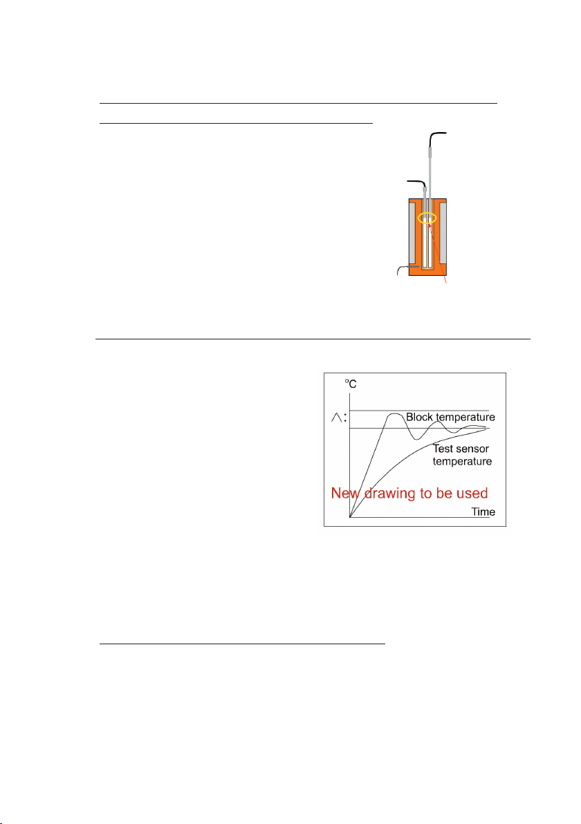
5.7 The Time Constant inuence on temperature-well mass
The sensor being tested has a
large time constant due to larger
mass and longer distance to the
cooling/heating elements.
Consequently, the temperature
curve for the internal reference
sensor and the sensor being
tested (center of insert) will be
different (see Figure 3
Temperature reference).
All Scan-Sense temperature
calibrators have an internal
reference sensor mounted in Figure 3. Temperature reference
the temperature block to react
quickly to temperature changes and thus reduce the resulting time
constant.
5.8 When to take the calibration reading
With the TC2000, when the REF temperature, that is the temperature
at the center of the well, has been stable +/- 0.2ºC for at
east 10 minutes (default value), the display will show the message
“Temperature stable, take reading”. Some temperature overshoot will
occur when approaching the SET temperature. However, this only
applies to the internal reference sensor. The sensor being tested has
Page 42
Page 43

a larger mass bacause of the insert, so it reacts more slowly to
temperature changes; see Figure 3 Temperature reference.
5.9 The importance of cleanliness to attain high accuracy
results
The ability of any dry-block calibrator to provide accurate calibrations
and performance depends on factors such as; sensor length,
sensor diameter, thermal-conductivity, the sensor position in the insert,
etc. cleanliness of the sensor, temperature well and insert is crucial to
the resulting accuracy of each calibration, you must ensure that all
surfacec are clean and free of dust, dirt, smudges and oxidaization.
5.10 Insulating with glass wool to minimize cold/heat loss
to surrounding air
Loss of cold or heat to the surrounding
air will occur when calibrating or testing
a long sensor thet is partly exposed
when it is placed into the calibrator.
When the sensor has a large exposed
mass, this cold or heat loss can affect
the accuracy of the calibration by as
much as 0.5ºC to 1ºC. As a general rule,
the effect of cold or heat loss is minimal
if the length of the part of the sensor that is exposed is less
than (<) 1/4 of its length. We recommend that the exposed part
of the sensore be insulated. Further, we recommend the use of
glass wool for insulation because, although there are different types
of insulating materials available, the material of choice must have
good insulating characteristics and be able to withstand extreme
operating temperatures. It must also be exible enough to be tucked
around the sensor, hence the choice of glass wool. Also bear in
mind that drafts can affect the stability of the calibrator. Please contact
ScanSense for further information.
Page 43
Page 44

TC2000 user’s manual
6 Specications
TEMPERATURE RANGE
Temperature range -40ºC* to +150ºC * Rel. ambient
Accuracy ±0.3ºC
Resolution 0.01ºC
Gradients at 95ºC w/water 0.06ºC
Stability (30 min. after normal stabilisation):
* As a dry block ±0.02ºC
* As a stirred liquid bath ±0.005ºC
* As a stirred ice bath ±0.001ºC
Uncertainty (best) <0.03ºC (depending on ext. ref.)
Well depth 155mm
Well diameter 50mm
Bath volume 261cm³
Thermostat test yes
Serial interface RS232
Power supply 110V(90-130V), 50/60Hz
230V(180-250V), 50/60HZ
Operating temp. 0 to +40°C
Dimensions 406x254x356 mm
Weight 15.5 kg without inserts
7 Electrical specications
INPUTS PORT A: RANGE RES. ACCURACY (% of reading)
Pt100 2, 3 and 4-wire* -50 to 800ºC 0.01ºC ±0.05ºC ±0.009%
Inputs Port B:
Pt100 2, 3 and 4-wire* -50 to 800ºC 0.01ºC ±0.05ºC ±0.009%
Type K -100 to 1370ºC 0.1ºC ±0,25ºC ±0,03%
Typr J -200 to 1200ºC 0.1ºC ±0.25ºC ±0.03%
Type E -200 to 1000ºC 0.1ºC ±0.25ºC ±0.04%
Type T -200 to 400ºC 0.1ºC ±0.25ºC ±0.03%
Type S 0 to 1760ºC 0.1ºC ±0.25ºC ±0.03%
Type R 0 to 1760ºC 0.1ºC ±0.25ºC ±0.03%
Type B +400to 1820ºC 0.1ºC ±0.25ºC ±0.03%
Type N -200 to 1300ºC 0.1ºC ±0.25ºC ±0.05%
Type L
Voltage** 0 to 10V 1µV ±0.25ºC ±0.02%
Current** 0 to 22mA 1µA ±2µV ±0.02%
Cold junction*** 0 to 40ºC 0.1ºC ±2µA ±0.25%
* Pt100 conforms to IEC751 and temperature scalev of ITS-90 TC input temperature drift 90ppm
** All thermocouple inputs are cold junction compensated V and mA input temperature drift 27ppm
*** Will in addition indicate negative inputs but these are not calibrated
Published specications may change without notice!
Page 44
 Loading...