

Page 1

TC125
TC150
TC400
TC650
TEMPERATURE CALIBRATORS
USER’S MANUAL
Manual revision: 15 March, 2001
SCSMANP004
Copyrighted © 2001
Page 2

User’s manual TC calibrators
Thank you
for purchasing a Tek Know temperature calibrators.
The Tek Know products are manufactured by Scan-Sense AS in accordance with our high quality standards in design, choice of components and workmanship in order to achieve maximum customer satisfaction and to fulfil our vision to be our customers “First Choice”.
The TC125, 150, 400 and 650 are designed and
manufactured by :
Scan-Sense AS T el. +47 33 36 30 00
Bekkeveien 163 Fax: +47 33 36 30 01
N-3173 Vear www.scansense.no
NORWAY post@scansense.no
2
Page 3

User’s manual TC calibrators
Contents
1.1 Certification 5
1 .2 W arranty 6
1.3 Notice 6
1.4 Safety 7
2. INTRODUCTION 9
3. CALIBRATORS TC650 & TC400 11
3.1 PREP ARA TION 11
3.1.1 Preparing the Heating calibrators for use. 11
3.1.2 Power Requirements TC400 & TC650 13
3.1.3 Fuses 12
3.2 GETTING ST ARTED 13
3.2.1 Power On 13
3.2.2 Celsius – Fahrenheit Setting 14
3.2.3 Default setting 14
3.3 HOW TO EXECUTE CALIBRA TIONS 15
3.3.1 Calibration Procedure 15
3.3.2 Calibration at High T emperatures 16
3.3.3 Precaution 16
3.3.4 Test of thermostats 17
3.4 CALIBRA TION HINTS 18
3.4.1 Time Constants 18
3.4.2 High Accuracy 19
3.4.3 Heat loss to the Surroundings 20
3.4.4 Cleaning of block and Insert 2 0
4.0 CALIBRATORS TC125 & TC150 21
4.1 PREP ARA TION 21
4.1.1 Preparing the TC125 & TC150 for use 21
4.1.2 Power Requirements 21
4.1.3 Fuses 22
4.2 GETTING ST ARTED 22
4.2.1 Power on 22
4.2.2 Celsius – Fahrenheit setting 23
4.2.3 Default setting TC125 & TC150 2 4
3
Page 4

User’s manual TC calibrators
4.3 HOW TO EXECUTE CALIBRATIONS 25
4.3.1 Calibration Procedure TC125 & TC150 2 5
4.3.2 Calibration at Low T emperatures 2 6
4.3.3. Precaution 27
4.3.4 Test of Thermostats 27
4.4 CALIBRA TION HINTS 28
4.4.1 Time constants 28
4.4.2 High Accuracy 2 9
4.4.3 Heat loss to the Surroundings 29
4.4.4 Cleaning of Block and Insert 3 0
4.4.5 Method of calibration 30
5. RS 232 INTERF ACE 31
6. TECHNICAL SPECIFICA TIONS 32
6.1 TC125 & TC150 32
6.2 TC650 & TC400 33
4
Page 5
User’s manual TC calibrators
1.1 Certification
Scan-Sense AS certifies that this product meets its published
specifications at the time of shipment from the factory . Scan-Sense AS
further certifies that its calibration measurements are traceable to
Norwegian Accreditation Standards and to the calibration facilities of
other International Standards Organisation members (FSO).
Scan-Sense AS declares that the following products :
TC125, TC150, TC400 and TC650
confirm to the following standards :
EN 500081-1 : 1992
EN 500082-1 : 1992
EN 61010 : 1993
EN 60742-1
IEC 801-2
DS 5104
5
Page 6

User’s manual TC calibrators
1.2 Warranty
These Tek Know products are warranted against defects in material
and workman-ship for a period of one year from date of shipment.
During the warranty period, Scan-Sense will, at its option, either repair
or replace products that prove to be defective.
The product must be returned to a service facility designated by Scan-
Sense for warranty service or repair. The foregoing warranty will not
apply to defects resulting from improper or inadequate maintenance by
buyer, buyer supplied software or interfacing, unauthorised modification
or misuse, operation outside of the environmental specifications for the
product, or improper site preparation or maintenance.
No other warranty is expressed or implied. Scan-Sense shall not be
liable for any direct, indirect, special, incidental, or consequential
damages, whether based on contract, tort, or any other legal theory.
1.3 Notice
All rights reserved. Reproduction of any part of this manual in any form
what so-ever without Scan-Senses expressed written permission is
forbidden.
All efforts have been made to ensure the accuracy of this manual.
However, should any errors be detected, Scan-Sense would greatly
appreciate being informed of them.
The above notwithstanding, Scan-Sense can assume no responsibility
for any errors in this manual or of their consequences.
6
Page 7

User’s manual TC calibrators
1.4 Safety
!
WARNING
The warning sign denotes a hazard. Such warning labels are fitted to
several places on the calibrators. It calls attention to a procedure which,
if not correctly performed or adhered to, could result in injury or loss of
life. Do not proceed beyond a warning sign until the indicated conditions
are fully understood and met. If you are in doubt please contact your
nearest Tek Know dealer.
A dry block calibrator is constructed in such a manner that it is impossible
to operate it without generating hot areas that can be of danger. It is
very important the operator in charge of the calibrator is aware of the
potential dangers and that he relays this information to any other future
user.
There are no operational switches or buttons inside the calibrator that is
needed during operation. Opening the calibrator during operation is very
dangerous due to high temperatures and high voltages. The calibrator is
only to be opened by qualified service personnel.
After the calibrator has been operated it may be very hot. Do not turn
off the calibrator if the temperature is above 400°C. The correct
procedure is to set the setpoint to 50°C. and allow it to cool below
100°C.
If the calibrator switches itself down during operation, this can be due
to the internal safety trip switch. In these cases please contact your
dealer because a new fuse will have to be installed.
7
Page 8

User’s manual TC calibrators
Failure to ground the temperature calibrator properly can result in
personal injury . Use grounded ac power outlet.
Place the temperature calibrator on an even surface and make sure
that the air inlet for the fan is not blocked. Connect the power cable to
the temperature calibrator and press the Line switch on the bottom
panel to turn it on. The calibrator must not be covered. The calibrator
must be used in an environment with free space of 0.5 m. above and
0.1 m, open space on either side and with satisfactory ventilation or
temperature control.
8
Page 9

User’s manual TC calibrators
2. INTRODUCTION
The TC calibrators user manuals are intended to be used with the Tek
Know portable calibrators TC125, TC150, TC400 and TC650. The
TC Calibrators are constructed with a dry temperature variable well,
with a special designed temperature controller. A digital controller with
a dedicated CPU gives the TC calibrators flexible controllability . Digital
control provides for adaptive control of the temperature, which saves
the operator time, and assures high accuracy and easy setting of
temperatures. The local LCD displays both the set temperature and
reference temperature simultaneously.
The display of the TC400 & TC650 has a resolution of 0.1°C, however
the PID controller works with a resolution of 0.01°C.Effectively this
means that a better stability than stated in the specifications may be
obtained. In order to obtain this, the calibration conditions must be ideal.
First and foremost, the ambient temperature must be kept stable state
and longer stabilisation time for the calibrator must be allowed. This is
to compensate for the temperature influence on the electronics. They
come in a dedicated instrument case with assessories such as cable
and inserts.
The communication port RS-232 comes as a standard feature, for use
with a computer in the calibration process. T ek Know provides optional
calibration software for temperature. The TC calibrators together with
the SC200 calibration software and SM300 Signal master will give you
an automatic calibration system.
9
Page 10
User’s manual TC calibrators
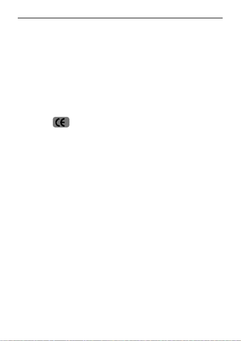
Pt 100 channel B
Figure 2-1, ‘Automatic calibration with internal reference’
RS232 Port 2
RS232 Port 1RS232 Port 1
PC with SC200
Signal Master SM300TC Calibrator
10
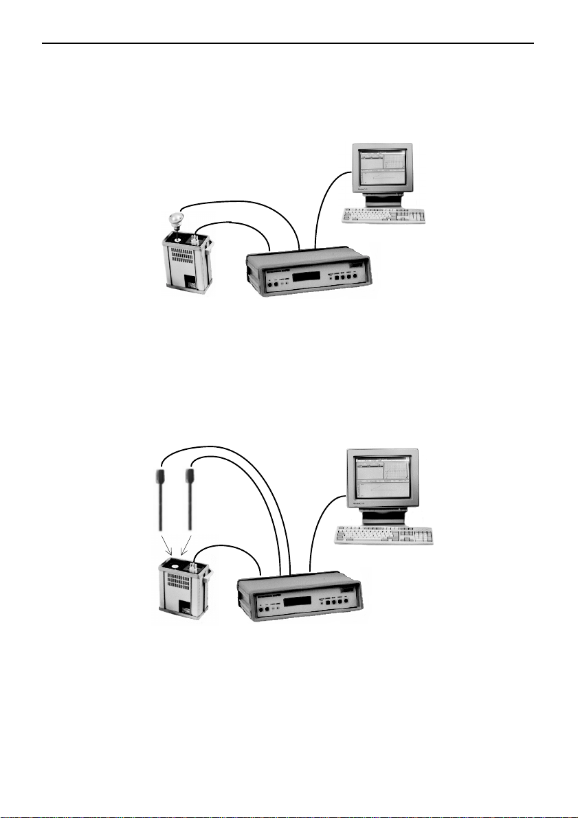
Ref. Pt 100
channel A
Pt 100
channel B
RS 232 port 1
RS 232 port 2
PC with SC200
Signal Master SM300TC Calibrator
Figure2-2, ‘Automatic calibration with external reference’
Page 11

User’s manual TC calibrators
3. CALIBRATORS TC400 & TC650
3.1 PREPARA TION
3.1.1 Preparing the heating calibrators for use.
Table 3-1. Items included with the TC400/650
temperature calibrators:
• T emperature calibrator: TC400 or 650
• Carrying case
• Power cord
• Test cable for thermostats
• T ool for changing inserts
• Insertion tube with 6.5 mm hole.
• Insertion tube with 10.5 mm hole.
• Calibration certificate
• User`s manual
3.1.2 Power requirements for TC400 & TC650
The TC400 & TC650 temperature calibrators areportable instruments
that require no physical installation other than connection to a grounded
ACpower source. Do not connect AC power until you have verified
that the line voltage is correct and that the proper fuse is installed.
Otherwise damage to the equipment may occure.
11
Page 12

User’s manual TC calibrators
Table 3-2. Power requirements for heating calibrators
100 Volt 110 Volt 230 Volt
Input Voltage 90 to 110 V 100 to 130 V 198 to 250 V
Frequency 50 to 60 Hz 50 to 60 Hz 50 to 60 Hz
Power consumption: 1600 W 1600 W 1600 W
Failure to ground the temperature calibrator properly can result in
personal injury . Use a grounded AC power outlet. Place the temperature
calibrator on an even surface and make sure that the air inlet for the fan
is not blocked. Connect the power cable to the
temperature calibrator and press the Line switch on
!
WARNING
m, open space on either side and with satisfactory ventilation or
temperature control.
the bottom panel to turn it on. The calibrator must not
be covered. The calibrator must be used in an
environment with free space of 0.5 m. above and 0.1
3.1.3 Fuses
The fuses used in the TC400 and TC650, 100 & 110Volt versions are
ø 6,3 x 32 mm ceramic 15 amp (slow).
The fuses used in the TC400 and TC650 -230 Volt versions are
ø 5 x 20 mm glass 10 amp (slow).
The fuses are placed next to the mains switch.
12
Page 13

3.2 GETTING ST ARTED
3.2.1 Power On
When the TC650 or TC400 is switched on the LCD display
on the front panel will show:
TC650 V 4.0
S.n. xxxxxx - ddmmyy
x denotes the serial no. of the calibrator and ddmmyy is the
date of last calibration of the calibrator.
V 4.0 indicates the software version no. of the calibrator.
After 10 sec. the display will show:
User’s manual TC calibrators
RE F. xxx.xxx C
SETPKT. xxx.xxx C
13
Page 14

User’s manual TC calibrators
3.2.2. Celsius – Fahrenheit setting
T o change the temperature notation press simultaneously the temperature
setting buttons é and ê while switching on the power to the calibrator .
The display will show :
C / F ?
After 2 sec. the display will show :
CELS. FAHR.
UP DOWN
Press the temperature setting button é for displaying the temperature
in Celsius. Press the temperature setting button ê for displaying the
temperature in Fahrenheit.
3.2.3 Default setting
The default setpoint setting for the
TC650 & TC400 is 30°C.
14
Page 15

User’s manual TC calibrators
3.3 HOW TO EXECUTE CALIBRA TIONS
3.3.1 Calibration procedure for TC400 and TC650
1. Move the adjustable handle to one side and turn on
the main switch.
2. Select an insertion tube that best fits the sensor to be tested.
3. Place the insertion tube in the thermo well and put the sensor
to be tested in the insertion tube. Insure that there is a good
contact between sensor and insertion tube.
Note: The insention tube and the well must be clean.
4. The sensor to be tested must be placed as close as possible
to the bottom of the thermo well in order to obtain the best
possible calibration result.
5. The calibration temperature Set Point is selected by means of
the arrow keys é and ê on the front panel of the calibrator.
It is indicated on the second line on the display SETPK.
6. The temperature in the thermo well is indicated in the first
line of the display REF .
7. The reference temperature will stabilise to the SETPKT.
When the reference temperature has been within ± 0.2°C of
the setpoint for 3 min. a * is visible after the last digit of the
REF. temperature. After 7 min. a second * appears behind
the SETPKT temperature, the calibrator is now stable to
within ± 0.1°C.
REF. 250.00*C
SETPKT. 250.00*C
15
Page 16

User’s manual TC calibrators
The temperature control within the TC400 and TC650 uses a specially
designed PID controller.Refer to chapter 3.4 for general requirements
to obtain the specified accuracy.
3.3.2 Calibration at high temperatures
The TC650 can generate temperatures up to 650 °C. The TC400 can
generate temperatures up to 400 °C. When using the calibrators at
these high temperatures, drafts may affect the stability of the calibrator .
In order not to expose the electronics to high temperatures over a longer
period of time we do not recommend to use the calibrator for more than
30 min. a time in the range 600-650 °C. If the calibrator os left at high
temperature for approximately 45 minutes, the setpoint will automatically
be set to 50°C.
3.3.3 Precaution
Please pay attention to the fact that RTD’s and thermocouples will
react quickly to temperature changes. Filled bulbs will react more slowly,
even if the TC650 & TC400 have stabilised, the sensor to be tested
may not yet have arrived at the indicated temperature. So when testing
filled bulbs or similar, please allow ample time for temperature
stabilisation. Some sensors are placed in long protection or extension
tubes and can not always be totally immersed in the thermo well.
16
!
WARNING
The metal tube may conduct heat or cold away from the
thermo well and this may affect the calibration. This can
be prevented by using insulation material on the part of the
sensor that is not immersed in the well. The part of the
sensor which is not immersed in the calibrator.
Never store the TC650 & TC400 in the carrying case
before the temperature in the thermo well is below 50°C.
Page 17

User’s manual TC calibrators
3.3.4 Test of thermostats
The TC650 & TC400 have a built-in test functions for thermostats.
Connect the alligator clips to the on-off function of the thermostat to the
calibrator. The test light on the front of the calibrator will indicate when
the on-off function of the thermostat is activated. Please pay attention
to the fact that thermostats react slowly to temperature changes.
17
Page 18

User’s manual TC calibrators
3.4 CALIBRATION HINTS
3.4.1 Time constants
The TC650 & TC400’s reference sensors are mounted in the heatingcooling block and will react quickly to temperature changes (small time
constant). The sensors being tested have a larger time constant due to
larger mass and longer distance to the heating-cooling elements.
Consequently the temperature curve for the reference sensor and the
sensor being tested will be different. See figure 3-1.
Figure 3-1 ‘ Temperature Response ‘
A certain overshoot will take place when approaching the Set point.
This speeds up stabilisation time for calibrations. This however only
applies to the reference temperature, as the sensor tested has a larger
mass and reacts more slowly to temperature changes, see fig. 3-1.
Consequently always make sure that before performing a calibration,
that the indicator for stable temperature in the calibrator (a * is shown
in the display after the SETPKT . temperature) is present and also take
into consideration the mass of the sensor being tested. When the TC650
& TC400 calibrators are used with the SC200 software in semiautomatic mode the PC will inform when the sensor being tested has
obtained its stabilisation.
18
Page 19

User’s manual TC calibrators
3.4.2 High accuracy
Dry block calibrators accuracy and performance to a given specification
is dependent on the fact that it reproduces the conditions for under
which it was calibrated.
There are several factors that may have affect on the accuracy of the
calibrators. There are variations in the sensor diameter , length, thermoconductivity, the active element’s position in the sensor, cleanness of
the sensor and fit in the insert from the one used during the calibrator’s
calibration.
For setpoint temperatures above 400 °C it is important that the insert
block and sensor is clean and free from dust and
oxidisation products.
Always approach the setpoint value from a lower temperature.
The TC400 and TC650 are calibrated dry using a Ø 6mm Industrial
Standard Reference Pt-100 sensor placed in the bottom of a 6,5mm
drilled insert.
Undrilled insertion tubes optional are availablefor custom drilling.
In these cases Scan-Sense can not guaranty for the calibrators
specifications.
To facilitate such calibration Scan-Sense can supply insertion tubes
with 2 or more holes according to specifications.
19
Page 20

User’s manual TC calibrators
3.4.3 Heat losses to the surroundings
When calibrating or testing a long sensor that is partly exposed when
mounted in the calibrator, a heat loss to the surroundings will result.
This is especially true when the sensor has a large mass that is exposed.
This heat loss will affect the accuracy , and may be as much as 0.5°C to
1.0°C. As a general rule, this error when minimal is the exposed length
of the sensor is < 1/4 of the length of the sensor. We recommend that
the exposed part of the sensor is insulated. See figure 3-2.
Figure 3-2 ‘ Insulation ‘
Different insulating materials may be used, but it is important that it can
withstand the operating temperatures and has a good insulation characteristic.It should be flexible so that it can be tucked around the sensor.
Consult Scan-Sense for further information.
3.4.4 Cleaning of block and insert
In order to obtain maximum and repetitive performance of the calibrator
it is important to keep the temperature well and insert as clean as possible
at all times. Before starting a calibration clean the well, insert and sensor
with fin wire wool or a wire brush. Gun bore cleaning tools are suitable
for this purpose (Not the solvents). Remove the dust from the cleaning
process with a dry cloth or compressed air.
20
Page 21

User’s manual TC calibrators
4.0 CALIBRA TORS TC125 and TC150
4.1 PREP ARATION
4.1.1 Preparing the cooling calibrators for use
Table 4 -1. Items included with the TC125 and TC150
Temperature Calibrator
• Temperature calibrator TC125 or TC150
• Carrying case
• Power cord
• Test cable for thermostats
• T ool for changing inserts
• Silicon oil and syringe
• Insertion tube 3.5 mm hole.
• Insertion tube 6.5 mm hole.
• Calibration certificate
• Users manual
4.1.2 Power requirements for TC125 and TC150
The TC125 and TC150 temperature calibrators are portable instruments
and require no physical installation other than connection to a grounded
ACpower source.
Do not connect AC power until you have verified that
the line voltage is correct and that the proper fuse is
!
WARNING
installed. Otherwise damageto the equipment may
occure.
21
Page 22

User’s manual TC calibrators
Table 1-2. Power requirements for cooling calibrators
110 Volt 230 Volt
Input Voltage 90 to 130 V rms 180 to 260 Vrms
Frequency 47 to 65 Hz 47 to 65 Hz
Power consumption 180 W 180 W
!
WARNING
Failure to ground the temperature calibrator properly can result in
personal injury. Use grounded AC power outlet.
4.1.3 Fuses
The fuse used in TC150 & TC125 is a
ø 5 x 20 mm 2.0 amp (slow) 230 V.
The fuse is placed next to the mains switch.
4.2 GETTING ST AR TED
4.2.1 Power on
When the TC125 or TC150 is switched on the LCD display on
the front panel will show:
22
Page 23

User’s manual TC calibrators
TC125 V 1.0
S.n. xxxxxx - ddmmyy
x denotes the serial no. of the calibrator and ddmmyy is the date of last
calibration of the calibrator. V 1.0 shows the software version no. of
the calibrator.
After 10 sec. the display will show:
RE F. xxx.xx C
SETPKT xxx.xx C
4.2.2 Celsius – Fahrenheit setting
T o change the temperature notation press simultaneously the temperature
setting buttons é and ê while turning on the power to the calibrator.
23
Page 24

User’s manual TC calibrators
The display will show :
After 2 sec. the display will show :
CELS. FAHR.
UP DOWN
C / F ?
Press the temperature setting button é for displaying the
temperature in Celsius.
Press the temperature setting button ê for displaying the
temperature in Fahrenheit.
4.2.3 Default setting TC125 and TC150
The default setpoint for the TC125 and TC150 is 20°C.
24
Page 25

User’s manual TC calibrators
4.3 HOW TO EXECUTE CALIBRA TIONS
4.3.1 Calibration Procedure TC125 & TC150
1. Move the adjustable handle to one side and turn on the main
switch.
2. Select the insertion tube that best fits the sensor to be tested.
3. Place the insertion tube in the thermo well and place the sensor
to be tested in the insertion tube and insure that a close contact
between sensor and insertion tube is obtained
4. The sensor to be tested must be placed as close as possible to
the bottom of the thermo well in order to obtain the best possible
calibration result.
5. The calibration temperature set point is selected by means of
the arrow keys and on the front panel of the calibrator. It is i
ndicated on the second line on the display SETPK.
6. The temperature in the thermo well is indicated on the first line
of the display . REF.
7. The reference temperature will stabilise to the SETPKT.
When the reference temperature has been within ± 0.2°C of
the setpoint for 3 min. a * is visible after the last digit of the
REF. temperature. After 7 min. a second * appears behind the
SETPKT temperature, the calibrator is now stable to within ±
0.1°C.
REF. -15.00 *C
SETPKT. -15.00 *C
25
Page 26

User’s manual TC calibrators
A PID controller is used in the TC125 & TC 150 to control the
temperature. Refer to chapter 4.4 for general requirements to obtain
the specified accuracy.
4.3.2 Calibration at low temperatures
The TC125 and TC150 can generate a temperature down to -40°C
below ambient temperature. In order to achieve best thermal coupling
to the sensor-undergoing test, a special silicon oil may be used in the
hole between the sensor and insert.
A calibration oil kit is supplied with the cooling calibrators TC125 &
TC150. This is a silicon based oil with a viscosity of 50 and has a
temperature range of -25
material present and comes in a 100 ml plastic bottle. It is supplied
together with a 10ml syringe in a plastic zip bag as a standard accessory
with all cooling calibrators from T ek Know . Additional oil is available
from Scan-Sense in 100ml bottles, order part no. P00267.
°C to + 150°C. The oil has no hazardous
26
Page 27

User’s manual TC calibrators
4.3.3. Precaution
Please pay attention to the fact that RTD’s and thermocouples will
react quickly to temperature changes. Filled bulbs will react more slowly
and even if the TC125 has stabilised, the sensor to be tested may not
yet have arrived at the indicated temperature. So when testing filled
bulbs or similar, please allow ample time for temperature stabilisation.
Some sensors are placed in long protection or extension tubes and can
not always be totally immersed in the thermo well.
The metal tube may direct heat or coldness away from
the thermo well, and this may affect the calibration. Using
!
WARNING
before the temperature in the thermo well is below 50°C.
4.3.4 Test of thermostats
insulating material on the part of the sensor, which is not
immersed in the calibrator, can prevent this.
Never store the TC125 and TC150 in the carrying case
The TC125 and TC150 has a built-in test function for thermostats.
Connect the alligator clips to the on-off function of the thermostat to the
calibrator. The test light on the front of the calibrator will indicate when
the on-off function of the thermostat is activated. Please pay attention
to the fact that thermostats may react slowly to temperature changes.
27
Page 28

User’s manual TC calibrators
4.4 CALIBRATION HINTS
4.4.1 Time constants
The TC125 and TC150’s reference sensor is mounted in the heatingcooling block and will react quickly to temperature changes (small time
constant). The sensors being tested has a larger time constant due to
larger mass and longer distance to the heating-cooling elements.
Consequently the temperature curve for the reference sensor and the
sensor being tested will be different. See fig. 4-1
Figure 4-1 ‘ Temperature Response ‘
A certain overshoot will take place when approaching the Setpoint
typically approximately 0.3°C. This speeds stabilisation time for
calibrations. This however only applies to the reference temperature,
as the sensor being tested has a larger mass and reacts more slowly to
temperature changes, see fig. 4-1.
Consequently make sure that before performing calibration, that the
indicator for stable temperatures in the calibrator (a * is shown in the
display after the SET POINT. temperature) is present and also take
into consideration the mass of the sensor being tested.
When using the TC125 & TC150 software in seem automatic mode the
PC will inform when the sensor being tested has obtained stabilisation.
28
Page 29

User’s manual TC calibrators
4.4.2 High accuracy
Dry block calibrators accuracy and performance to a given specification
is dependent on the fact that it reproduces the conditions for under
which it was calibrated.
There are several factors that may have affect on the accuracy of the
calibrators. There are variations in the sensor diameter , length, thermoconductivity, the active element’s position in the sensor, cleanness of
the sensor and fit in the insert from the one used during the calibrator’s
calibration.
Undrilled insertion tubes optional are available for custom drilling.
In these cases Scan-Sense can not guaranty for the calibrators
specifications. To fabricate such calibration Scan-Sense can supply
insertion tubes with 2 or more holes according to specifications.
4.4.3 Heat loss to the surroundings
When calibrating or testing a long sensor that is partly exposed when
mounted in the calibrator, a heat loss to the surroundings will result.
This is especially true when the sensor has a large mass that is exposed.
This heat loss will affect the accuracy, and may be 0.5°C to 1.0°C.
As a general rule, the exposed length of the sensor should be <1/4 of
the length of the sensor. We recommend that some of the exposed part
of the sensor be insulated.
See fig. 4-2.
Figure 4-2 ‘ Insulation
29
Page 30

User’s manual TC calibrators
Different insulating materials may be used, but it is important that it can
withstand the operating temperatures and has a good insulation
characteristic. It should be flexible so that it can be tucked around the
sensor. Consult Scan-Sense for further information.
4.4.4 Cleaning of block and insert
In order to obtain maximum performance of the calibrator, it is important
to keep the temperature well and insert as clean as possible. Before
starting a calibration, clean the well and insert. The insert is cleaned
using a dry cloth. Compressed air may be used to clean the well.
4.4.5 Method of calibration
During the calibration of the calibrator a silicon oil was used in the
insert in order to obtain a good thermal conduction between the insert
and the reference thermometer. This silicon oil was used during the
entire calibration of the calibrator.
We recommend therefore that silicon oil be used in the insert when
using the calibrator in order to obtain the same conditions as when the
calibrator was calibrated.
30
Page 31

User’s manual TC calibrators
RS 232 INTERF ACE
The TC Calibrators are supplied with an RS 232 port for connection to
a PC as a standard.
To ease the calibration taskand save man-hours, Scan-Sense have
developed a Windows® based software SC200.By using the SC200
software, automatic calibration can easily be done by the user.
Data can be presented in a calibration report that takes into account the
ISO 9000 specifications, procedures, set-up and traceability.
It will also generate a simple database for your sensors and temperature
circuits. The software will be of a significant time saving factor for the
operator, when at the same time it is almost self instructive in use.
SETUP:
Baudrate : 9600 baud
no parity
8 bits
1 stop bit
9 pin D-SUB female connector,
Tx pin 2
Rx pin 3
Gnd pin 5
The TC Calibrators communicate with the SC200 PC based calibration
software using an eight-byte communications protocol. All parameter
settings and control can be set remotely using the SC200 software.
31
Page 32

User’s manual TC calibrators
6. TECHNICAL SPECIFICA TIONS
6.1 TC125 & TC150
lledoM521CT051CT
*egnarerutarepmeTC°521+otC°04-C°051+otC°04-
egnardetarbilaCC°521+otC°02-C°051+otC°02-
noituloseR10.0C° 10.0C°
ycaruccA3.0±C° 3.0±C°
ytilibatS30.0±C° 30.0±C°
emitgniloocxaMnim02nim02
emitgnitaehxaMnim51nim05
htpedlleWmm011mm011
retemaidlleWmm91mm91
tsettatsomrehTseysey
232SRseysey
egatloveniL)V031-09(011)V031-09(011
noitpmusnocrewoPW081W081
snoisnemiDmm572x521x522mm572x521x522
thgieWgk8,6gk8,6
egnar.pmetlanoitarepO0C° C°04+otC°04+otC°0
* Min. temp is relative to ambient temp.
32
)V062-081(032)V062-081(032
Page 33

User’s manual TC calibrators
6.2 TC650 & TC400
lledoM004CT056CT
*egnarerutarepmeTC°004+otC°05C°056+otC°05
egnardetarbilaCC°004+otC°05C°056+otC°05
noituloseR1.0C° 1.0C°
ycaruccA3.0±C° 5.0±C°
ytilibatS30.0±C° 50.0±C°
emitgnitaehxaMnim21nim81
htpedlleWmm551mm551
retemaidlleWmm62mm62
tsettatsomrehTseysey
232SRseysey
egatloveniLCAV011CAV011
V011-09V011-09
egatloveniLCAV011CAV011
V031-011V031-011
egatloveniLCAV032CAV032
V052-891V052-891
noitpmusnocrewoPW0061W0061
snoisnemiDmm572x521x522mm572x521x522
thgieWgk3,7gk3,7
egnar.pmetlanoitarepO0C° C°04+otC°04+otC°0
33
Page 34

User’s manual TC calibrators
Notes:
34
Page 35

Notes:
User’s manual TC calibrators
35
Page 36

User’s manual TC calibrators
Notes:
36
 Loading...