

Scanreco D2JOYTR03FH917 Users Manual
Operating instructions
DRC-J joystick control system
310107 EN / PDF 311007
214 975 44
42680544.eps
720 IS 975

Manufacturer
Contents
Demag Cranes & Components GmbH
P.O. Box 67, D-58286 Wetter
Telephone (+2335) 92-0 · Telefax (+2335) 927676
www.demagcranes.com
Page
1 Foreword 4
1.1 Copyright 4
1.2 Customer service 4
1.3 Liability for Defects 5
1.4 Limitations of liability 5
1.5 Definitions 6
2 Safety instructions 7
2.1 Symbols 7
2.2 Appropriate use 7
2.3 Inappropriate use 9
2.4 Basic information on safety 9
2.5 Safety instructions for installation and disassembly 10
2.6 Safety instructions when first putting into service
after completing installation 11
2.7 Safety instructions for operation 11
3 General description 12
3.1 Transmitter/receiver interface 12
3.2 Transmission method 12
4 Selection of unit 14
4.1 DRC-J scope of delivery 14
4.2 Available radio receivers 14
4.3 Accessories for crane identification 14
4.4 Casing seal/seal breakage 14
5 Identification and display functions 15
5.1 Joystick control unit 15
5.2 LCD display 16
5.3 Identification labels for the crane installation 20
6 Putting the radio control system into operation after installation 22
6.1 Putting into operation 22
6.2 Putting a radio remote control system with DRC-J into operation 23
6.3 Configuration of a radio remote control system for DRC-DR 28
7 Operation of the radio control system 29
7.1 Checks before starting work 29
7.2 Crane operation/Run 31
7.3 Taking out of service at the end of the shift 33
7.4 Operating statuses of the radio control system 33
8 Joystick control unit power supply 35
8.1 General description 35
8.2 Display of available battery capacity 36
8.3 Charging the batteries 36
2
8.4 Replacing the batteries 37

Page
9 Information menu in connection with DRC-DR 38
9.1 Activating the Information menu 38
9.2 Selecting the information source 38
9.3 Starting screen 38
9.4 Navigating in the information menu 38
9.5 Data of the Information menu 39
10 Technical data 40
10.1 Dimensions 40
10.2 International postal registration 41
11 Eliminating faults 42
EC conformity declaration 44
DRC-J joystick control system parameter programming
(For authorized personnel only) 45
1 Menu for programming parameters of the joystick control system 46
1.1 Activating the menu 46
1.2 Displaying the current parameters 46
1.3 Displaying the serial number of the joystick control system
Parameter code 001 46
1.4 Displaying the software version of the joystick control system
Parameter code 002 47
1.5 Displaying the hardware version of the joystick control system
Parameter code 003 47
1.6 Displaying and entering a fixed frequency channel,
Parameter code 004 47
1.7 Displaying and entering the cut-out time in STOP mode,
Parameter code 005 48
1.8 Displaying and entering the cut-out time in Run mode,
Parameter code 006 49
1.9 Frequency hopping 50
Accompanying documents:
DRC-MP operating instructions 214 994 44 720 IS 975
DRC-DR operating instructions 214 953 44 720 IS 975
3

1 Foreword
You have purchased a Demag product/system.
These operating instructions are designed to provide the owner with appropriate
instructions for safe and correct operation and to facilitate maintenance.
Every individual given the task of transporting, installing, commissioning,
operating, maintaining and repairing our products and systems must have read
and understood
the operating instructions
the safety regulations and
the safety instructions in the individual chapters and sections.
The operating instructions must be available to the operating personnel at all
times in order to prevent operating errors and to ensure smooth and trouble-free
operation of our products/systems.
1.1 Copyright
1.2 Customer service
These operating instructions must be treated confidentially. They should only be
used by authorized personnel. They may only be entrusted or made available to
third parties with the prior written consent of Demag.
All documents are protected within the sense of copyright law.
No part of this documentation may be reproduced, utilized or transmitted without
specific prior consent. Infringements are an offence resulting in obligatory
compensatory damages.
All industrial rights reserved.
Our after-sales service will provide you with all technical information on Demag
products and their systematic application.
Should you have any questions regarding our products, please refer to one of our
after-sales service stations, the relevant representative or the manufacturer.
Kindly quote the serial or order number (see test and inspection booklet, load
capacity plate on the crane) in any correspondence or for spare part orders.
Specifying this data ensures that you receive the correct information or the
required spare parts.
4

1.3 Liability for Defects
These operating instructions must be read carefully before installing and putting
the system into operation.
We assume no liability for any damage and malfunctions resulting from failure to
comply with the operating instructions.
Any liability claims for defects must be made by quoting the order number
immediately on detecting the defect.
Any liability claims for defects are void in the event of:
inappropriate use,
faulty devices or equipment connected or attached to the system which are not
part of our scope of supplies and services,
use of non-genuine spare parts and accessories,
refurbishment or modification of the product unless approved in writing by
Demag.
Wearing parts are not subject to liability for defects.
1.4 Limitations of liability
All technical information, data and instructions for operation contained in these
operating instructions were up-to-date on going to print and are compiled on the
basis of our experience and to the best of our knowledge.
We reserve the right to incorporate technical modifications within the scope
of further development of the system which is the subject of these operating
instructions.
Therefore, no claims can be derived from the information, illustrations and
descriptions contained in these operating instructions.
The descriptions and illustrations contained in this documentation do not necessarily correspond to the scope of delivery or any subsequent spare part delivery,
either; the drawings and illustrations are not to scale.
Only documentation belonging to the actual order is valid.
We assume no liability for damage and malfunctions caused as a result of
operating errors, non-compliance with these operating instructions or inappropriate
repairs and maintenance.
We expressly point out that only genuine Demag spare parts and accessories approved by us may be used. Accordingly, this also applies to other manufacturers
parts supplied by us.
For safety reasons, the fitting and use of spare parts or accessories which have
not been approved and unauthorized modification and conversion of the product
are not permitted and exempt us from any liability for damages resulting therefrom.
With the exclusion of any further claims, we are liable for any defects or omissions
on our part in the products or documentation supplied within the scope of the liability obligations entered into in the original contract. Any further claims, in particular
any and all claims for damages, are excluded with the exception of legal claims in
accordance with product liability legislation.
5

1.5 Definitions
Owner
Owners (employer, company) are defined as a person who owns such a system
and who uses it appropriately or allows it to be operated by suitable and instructed
persons.
Operating personnel/operator
Operating personnel or operators are defined as persons entrusted by the owner
of the system with the operation of the system.
Specialist personnel
Specialist personnel are defined as persons assigned by the owner of the system
to carry out special tasks such as installation, setting-up, maintenance and fault
elimination.
Qualified electrician
Qualified electricians are defined as persons who, owing to their technical training,
knowledge and experience of electrical installations as well as knowledge of the
relevant standards, codes of practice and regulations, are able to assess the tasks
given to them and to identify and eliminate potential hazards.
Trained person
Trained persons are defined as persons who have been instructed and trained
for the tasks assigned to them and on the possible hazards resulting from incorrect handling and who have been informed about the required protective devices,
protective measures, relevant regulations, codes of practice, accident prevention
regulations and operating conditions and who have proven their qualifications.
Experienced technician
Experienced technicians are defined as persons, who, owing to their technical
training and experience, have sufficient knowledge of these systems and are familiar with the relevant national industrial safety regulations, codes of practice,
accident prevention regulations, directives and generally accepted engineering
standards enabling them to judge the safe operating condition of such systems.
6
2 Safety instructions
2.1 Symbols
2.2 Appropriate use
These symbols are used to warn against potential safety hazards or causes of
damage or provide useful information.
Hazard warning
This symbol appears in the operating instructions next to all instructions relating to
safety at work wherever a potential danger to life and limb exists.
Follow these instructions at all times and be particularly vigilant and cautious.
Pass on safety instructions to all persons entrusted with working on the product
including the power supply.
In addition, observe all general safety regulations at all times.
Warning against dangerous electrical voltage
Contact with live parts can result in immediate death. Protective covers (e.g.
covers and enclosures) marked with this sign may only be opened by qualified
electricians. Before opening, all relevant operating, control, feed or other voltages
must be disconnected.
Operating hazard for the installation
This symbol in the operating instructions indicates all warnings which, if not
complied with, may result in damage to the product.
The DRC-J joystick control system is intended to be used as an operating unit and
transmitter station for the DRC-DR and DRC-MP radio receivers. The scope of
functions is preferably designed for wireless control of crane installations, travelling
hoist units, chain and rope hoists, transfer carriages and similar applications.
The operator can position himself as required. He can control loads and movements from a safe distance. He must always select a location to ensure that all
movements of the load and the crane can be monitored and any hazardous movement can be switched off within an appropriate time. Before starting a crane movement by actuating the operating element, the operator must determine which crane
is being controlled. The display of the DRC-J joystick control unit shows the identification/crane number of the controlled crane. The radio-controlled crane must be
identified by means of the identification/crane number in a way clearly visible to the
operator.
If required, a signal must be actuated prior to a crane movement for acoustic
control.
7

DRC transmitters and receivers meet the requirements of the standards and
regulations listed in the EC conformity declaration. The specified EC conformity
declaration is an integral part of the relevant operating instructions.
Transmitters and receivers of the DRC range can be operated without any
registration or operating fee. The benefits that this provides for the user are also
utilised by some other manufacturers of devices for communications and telemetry
applications. The consequence of this is that the relevant approved frequency
ranges may be used by many transmitters at the same time, depending on the
time and location.
The transmission method used by Demag is designed for the most robust and
interference-resistant radio transmission between the transmitters and receivers
of the DRC range.
The state-of-the-art transmission method is provided with technical features (e.g.
frequency hopping) which are intended to ensure a minimum of conflicts for radio
operation together with other transmitter and receiver devices which use the same
frequency range.
Despite all of the technical precautions taken by Demag, it cannot be entirely excluded that the transmission characteristics of other radio systems are impaired,
in particular devices supplied by other manufacturers that use the same frequency
range, or that the transmission characteristics of the system supplied by Demag
are negatively affected. In such cases, interference or radio connection interruptions may occur, which disrupt the communication and function of a system supplied by Demag or other manufacturers. Such impairment or interference does not
constitute a defect on the part of DRC transmitters and receivers. Demag will only
accept liability for wilful or grossly negligent behaviour on its part.
The number of transmitters that operate without any interference in a given area
depends on the relevant radio solution design of all systems and the selectivity of
each individual system.
If this limit is exceeded continuously or for certain periods, additional technical
measures may be necessary in order to ensure simultaneous and interferencefree operation of the radio systems. Whether and to which extent such measures
are required can only be determined by means of suitable measurements on site
or when the system is put into operation. Demag is not responsible for such additional technical measures.
Radio remote control systems of the DRC range are exclusively intended for
single-transmitter operation; i.e. there is always a clear assignment between a
specific transmitter and the corresponding receiver.
The DRC-J joystick control system may only be operated when in perfect working
order by trained personnel in accordance with the relevant safety and accident
prevention regulations. This also includes compliance with operating and maintenance conditions specified in the operating instructions.
In Germany, the owner of a crane installation with radio control system is
responsible for compliance with accident prevention regulations BGV D6.
DRC-J joystick control units that are ready for operation must not be left
unattended They must be protected against unauthorized use.
For appropriate use, the information in the operating instructions for the receiver
used (DRC-DR/DRC-MP) and the machine/crane installation to be controlled
must be complied with in addition to the information contained in these operating
instructions.
Serious personal injury or damage to property may occur in the event of:
unauthorized removal of covers,
inappropriate use of the product/system,
incorrect operation,
insufficient maintenance,
working on live parts.
8

2.3 Inappropriate use
Certain work and practices are prohibited when using the system as they may
involve danger to life and limb and result in lasting damage to the product, e.g.:
Manipulating electrical equipment
Connecting the unit to power supply with voltage or frequency other than those
specified on the type plate
Non-compliance with specified mounting positions
Non-compliance with the max. permissible operating temperature.
Other inappropriate applications may be caused by non-compliance with the
information in the operating instructions for the radios receiver used (DRC-DR/
DRC-MP) or for the machine to be controlled.
2.4 Basic information on
safety
Persons under the influence of drugs, alcohol or medicines which affect reactions
must not install, operate, put into service, maintain, repair or disassemble the
product. Any conversions and modifications to the installation must comply with
the safety requirements. Work on electrical equipment may only be carried out by
specialists in accordance with electrical regulations.
In the event of malfunctions, the system must be shutdown, switched off and the
relevant main switches locked immediately.
Malfunctions must be eliminated immediately.
National accident prevention regulations and codes of practice and general safety
regulations must be observed when operating our products. Important information
and instructions are marked by corresponding symbols. Follow these operating
and safety instructions to avoid personal injury and damage to machinery.
The operating instructions must be kept available at the place where the system is
in use at all times.
They include significant aspects and appropriate excerpts from the relevant guidelines, standards and regulations. The owner must instruct his personnel appropriately. If the safety instructions given are not observed in any way, personal injury
or even death can result.
Observe general statutory and other obligatory regulations relating to accident
prevention and environmental protection and basic health and safety requirements
in addition to those included in these operating instructions.
Such requirements may also relate, for example, to the handling of hazardous
materials or the provision/wearing of personal protection equipment.
Comply with these regulations and general accident regulations relevant for the
place at which the system is used and follow the instructions therein when working
with the system.
The system may still constitute a danger to life and limb if it is not installed, operated, maintained or used appropriately by personnel which have not been trained
or specially instructed.
The safety instructions must, if required, be supplemented by the owner with instructions and information (e.g. factory regulations) relating to organization of work,
working procedures, operating personnel, etc. Supervising and reporting obligations as well as special operating conditions must also be taken into consideration.
Supervising and reporting obligations as well as special operating conditions must
also be taken into consideration.
Personnel assigned to working with the system must have read the operating instructions and the safety instructions.
All activities relating to the system which are not described in the operating
instructions may only be carried out by specifically trained specialist personnel.
The owner must ensure that personnel work in a safety and hazard-conscious
manner in compliance with the operating instructions.
The owner must ensure that the system is only operated when in proper working
order and that all relevant safety requirements and regulations are complied with.
9

The system must be taken out of service immediately if functional defects or
irregularities are detected.
In the event of a stoppage (e.g. if defects regarding safe and reliable operation are
detected, in emergency situations, in the event of operating malfunctions, for maintenance purposes, if damage is detected or after finishing work), the operator/experienced technician must carry out all prescribed safety measures or observe that
they are automatically carried out.
Personal protective clothing must be worn as necessary or as required by regulations. Personnel must not wear loose clothing, jewellery including rings or long hair
loose. Injury may occur, for example, by being caught or drawn into the mechanism.
All safety and hazard warnings on the product, its access routes and mains connection switches must be preserved completely and in legible condition.
Modifications, additions to and conversions of the product which might impair
safety in any way must not be carried out without the approval of Demag.
Safety devices must not be rendered inoperative.
Only genuine Demag spare parts may be used. Observe prescribed deadlines or
those specified in the operating instructions for routine checks/inspections.
2.5 Safety instructions for
installation and disassembly
Installation and disassembly work may only be performed by experienced
technicians.
Installation and disassembly work must be co-ordinated by the person carrying
out the work and the owner within the scope of their responsibility.
The assembly zone must be made safe.
The installation must be isolated in accordance with the relevant electrical
regulations.
Customer-specific regulations must be observed.
Only appropriate, tested and calibrated tools may be used.
In the case of disassembly, any waste material must be disposed of by the owner
in an environmentally compatible way in compliance with the valid regulations.
10

2.6 Safety instructions
when first putting the
unit into service after
completing installation
The working area must be made safe.
First check that the voltage and frequency specified on the type plates match
the owner s mains power supply.
In the course of putting the product into service, it may be necessary to render
safety devices or features inoperative when carrying out adjustments or function
checks.
When putting the machine into service, it may be necessary to perform work in
the danger zone, therefore, it must be ensured that only appropriately trained
personnel are employed for this work.
2.7 Safety instructions for
operation
Before putting the crane into operation, the operating personnel must be satisfied
that the radio control system is in safe and correct operating condition.
In addition, the safety instructions and measures contained in the operating instructions of the crane must be applied.
The clear assignment between the DRC-J joystick control system to the radio
receiver (DRC-DR/DRC-MP) on the crane is the precondition for safe wireless
remote control of a crane. This unique assignment is created by the exchange
of the address features between transmitter and receiver when a DRC-J joystick
control system is put into operation. The operating personnel recognises which
crane is controlled by means of the crane identification shown in the display of the
joystick control unit.
Before switching on/putting into operation of the crane/machine controlled by the
radio control system with the DRC-J joystick control system, it must be ensured
that nobody is endangered by operation of this crane.
If the operator notices persons who may be exposed to a risk to health or personal
safety by operation of the equipment, he must suspend operation immediately and
may not resume operation again until the persons are outside the danger zone.
STOP key function
Actuation of the red STOP key activates the emergency-stop function in the radio
receiver on the crane. The emergency-stop function stops any potentially dangerous movement of the crane. For use of the emergency-stop function, in particular the instructions contained in the operating instructions of the crane must be
complied with. When the STOP key has been actuated, the radio system is in the
!STOP" operating mode. No movement commands are transmitted. The STOP
key latches when actuated. To quit the EMERGENCY stop function, first turn the
STOP key to unlock it and then actuate the Start/Horn key. This may only be done
after the operator has made sure that the hazardous situation which resulted in
actuation of the STOP key has been eliminated.
Warning device function
Radio-controlled cranes must be provided with a warning device (acoustic or
optical). The crane operator can activate this warning device by means of the
horn key to warn persons in the vicinity of the crane and/or load before starting
the crane movements. The warning device must also be used if the crane operator
intends to check the assignment between the joystick control unit and the crane
receiver by means of a joystick control command.
Range of the radio remote control system
The crane operator may only use the range of the radio control system to the extent that he can freely monitor the danger zone of the crane movements.
The range of the hand-held radio transmitter is limited and can be additionally
reduced by ambient conditions. The range may also be limited by utilization of
the available frequency range by other radio transmitters. The quality of the radio
signal is shown in the display of the joystick control unit. If poor connection quality
is displayed, unintended interruptions of the controlled movements may occur.
11
3 General description
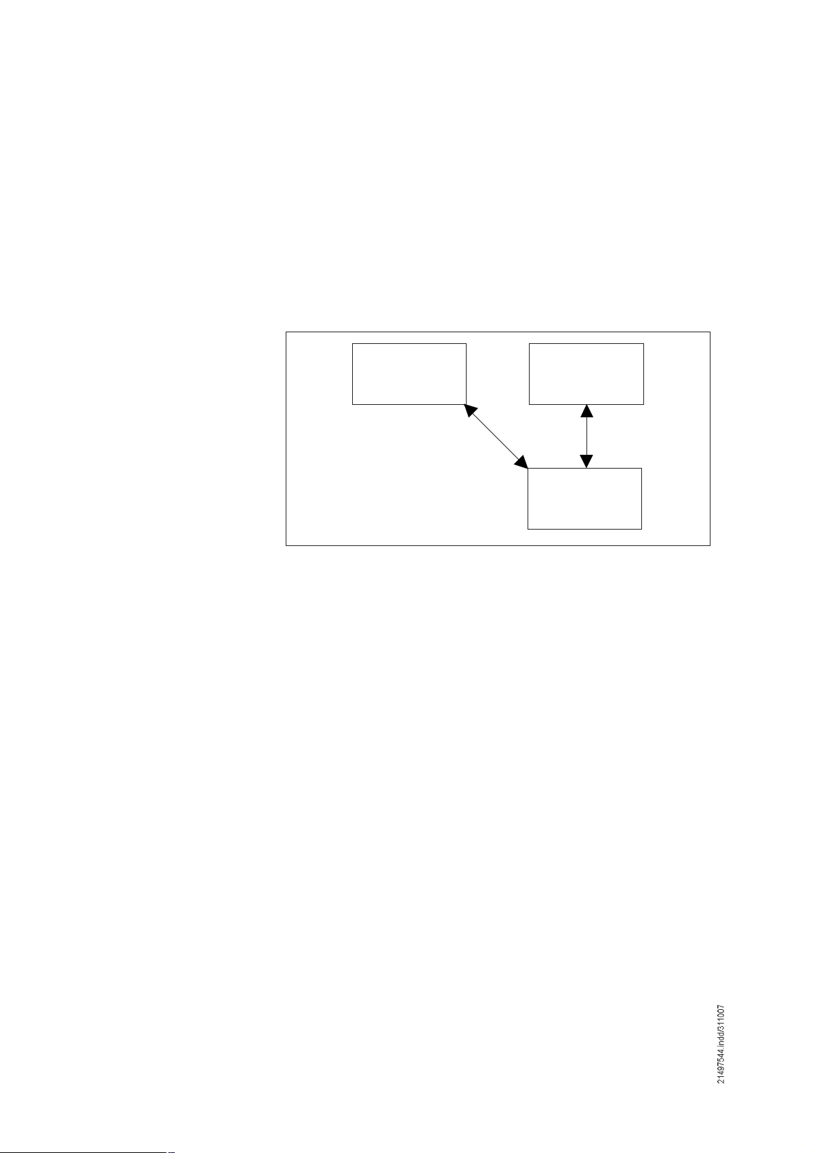
3.1 Transmitter/receiver
interface
Demag DRC radio control systems are designed for wireless control of hoist units
and cranes. They are the interface for manually controlled crane installations. The
applicable EC directives and standards are complied with for this application.
Demag DRC radio control systems consist of a radio transmitter/operating unit and
a radio receiver with interface to the crane control system.
DRC-J joystick control systems in applications in connection with DRC-DR or
DRC-MP radio receivers are the subject of these operating instructions.
Radio receiver
DRC-DR
The Demag DRC-DR radio receiver is a pluggable PCB for installation in the
electrical equipment cover of the DR hoist unit. The interface of this receiver
component to the crane control system and power supply by the DR electrical
equipment is the CAN safety bus. The DRC-DR radio receiver is exclusively
suitable for operation with a DR hoist unit.
The Demag DRC-MP radio receiver is a complete unit with its own enclosure
and power supply from the control voltage network of the crane installation.
Relay contacts for the individual control commands and the EMERGENCY stop
circuit form the interface of this unit to the crane control system. An additional
semiconductor output with pulse width modulation is provided for infinitely variable crane drives. The DRC-MP radio receiver is suitable for a wide range of
applications.
Demag radio receivers are provided for duplex operation and transmit information
to the DRC-J joystick control system. This increases safety of the radio system.
Status information of the crane control system and the receiver are shown in the
display of the DRC-J joystick control unit.
Radio receiver
DRC-MP
Joystick control unit
DRC J
3.2 Transmission method
12
The so-called ISM band (433 MHz) is used for transmitting the radio signals
between transmitter and receiver. Witin the ISM band 30 frequencies are used
alternately in a defined sequence (so-called frequency hopping). A random-check
generator detemines the sequence of the frequencies when radio transmission is
started. In order to increase transmission reliability, the information is transmitted
several times. This method in connection with frequency hopping provides for a
very high immunity to interference.
Frequency hopping is used for the first time with Demag DRC radio control system
types D1-FH and D2. In the case of the D1 type, the frequency of the radio signal
is not changed during a transmission cycle.
A decisive advantage of the frequency hopping transmission is that existing information contents are transmitted on several physical channels. This redundant
radio transmission 1) provides for an exceptionally high insensitivity of radio
transmission against other transmitters or electromagnetic interference.
1) Certain information contents are transmitted on up to 5 different frequencies. Only if (theoretically)
all frequencies used were occupied or disturbed by other radio systems, communication would be
interrupted.
3.2.1 Downwards compatibility of
DRC-10 D2 transmitters
For combining DRC-10 D2 transmitters with D1 type receivers
DRC-DR, part no. 719 441 45
DRC-MP, part no. 773 432 44
these transmitters must be programmed for operation at a fixed frequency (chapter
#Programming parameters of the DRC-10 handheld transmitter!, section 1.6).
The table below shows an overview of the possible combinations
3.2.2 Compatibility
D1, D1 FH and D2
3.2.3 Frequency hopping feature
Receiver
Design
D1
D1
D1 FH
D1 FH
D2
Product
Part no.:
DRC-10
773 431 44
DRC-J
773 460 44
DRC-10
773 581 44
DRC-J
773 583 44
DRC-10
773 591 44
D1
DRC-MP
773 432 44
Fixed
frequency
Fixed
frequency
Fixed
frequency
D1
DRC-DR
719 441 45
OKOK
OKOK
Fixed
frequency
Fixed
frequency
Fixed
frequency
D1 FH
DRC-Mp
773 584 44
compatible
compatible
D1 FH
DRC-DR
719 436 45
not
not
OKOKOK
OKOKOK
OKOKOK
not
compatible
not
compatible
D2
DRC-DR
719 439 45
not
compatible
not
compatible
Explanation:
D1 without frequency hopping
D1 FH with frequency hopping
D2 with frequency hopping and, if required, with extended functions
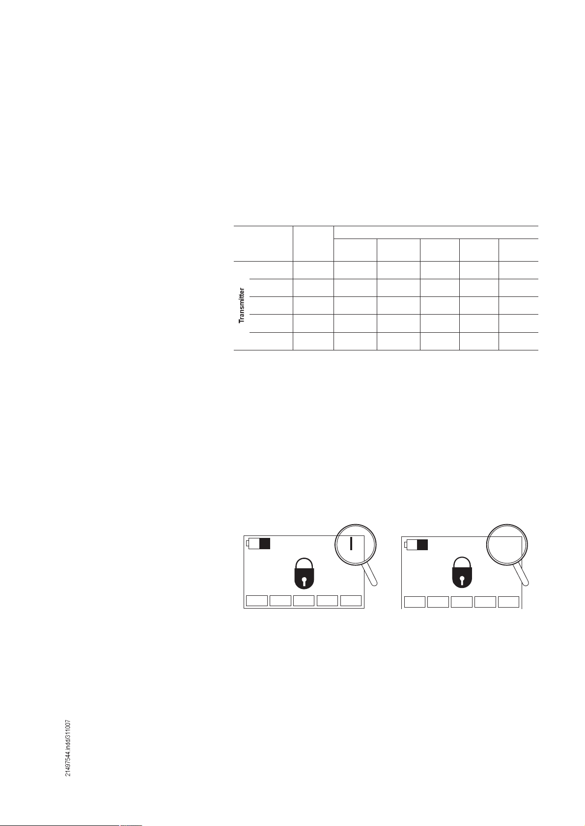
Transmitters and receiver with frequency hopping can be identified by the part no.
on the rating plate.
Additionally transmitters with frequency hopping have a different symbol for the
signal strength in the display.
Transmitter without frequency hopping Transmitter with frequency hopping
ÒÑ×Ü
42718344.eps
ÒÑ×Ü ááá
42718244.eps
13

4 Selection of unit
4.1 DRC-J scope of
delivery
4.2 Available radio
receivers
4.3 Accessories for crane
identification
Part no.:
DRC-J D1 FH joystick control system set 773 583 44
Contents of the complete delivery
1 DRC-J D1 FH joystick control unit
1 Rechargeable battery 1) NiMH 7,2 V 773 462 44
1 Battery charger 230 VAC 50 Hz 250 mA 773 463 44
1 Shoulder strap 773 461 44
1 Operating instructions DRC-J joystick control system 214 974 44
1 Key symbols for transmitter DRC J 773 439 44
DRC-DR D2 radio receiver 719 439 45
DRC-MP D1 FH radio receiver 773 584 44
Coding labels Carrier foil, black 895 639 44
Coding labels 7 segments (yellow) 895 640 44
Travel direction foil cross travel 895 635 44
Travel direction foil long travel 895 637 44
Aerial for DR 3, 5, 10, 20 (433 MHz ISM band) 719 445 33
Patch aerial for 433 - 434 MHz.frequency
range. Installed on DR electrical equipment
cover.
For installation refer to 203 638 44
Note:
4.4 Casing seal/seal
breakage
For application of the DRC-J radio remote control system in crane installations, the owner must observe the regulations and instructions of the BGV
D6.
All components are designed for operation in industrial environments.
The DRC-J joystick control system has been built in compliance with the regulations and rules of the BGV D6 for cranes, the ZH 1/547 guidelines for radio remote
control systems of cranes and the EN 60204-32 as well as the EN 954-1.
All units have been tested in accordance with the EMC directives and comply
with the relevant standards regarding interference emission and resistance to
interference for application in industrial environments.
To comply with the EMC requirements, the following points must be considered for
integration into overall systems:
Integration of electronic components to meet EMC requirements
Use of prescribed or approved cables, screened cables, if required.
The DRC-J joystick control system is sealed in the factory.
The equipment, and particularly the joystick control unit, may only be opened for
repair purposes by authorised parties.
Breaking of a casing seal such as this will result in loss of all warranty
rights!
14
1) Service life of the rechargeable battery in charging cycles to IEC 61951, more than 500 charging
cycles
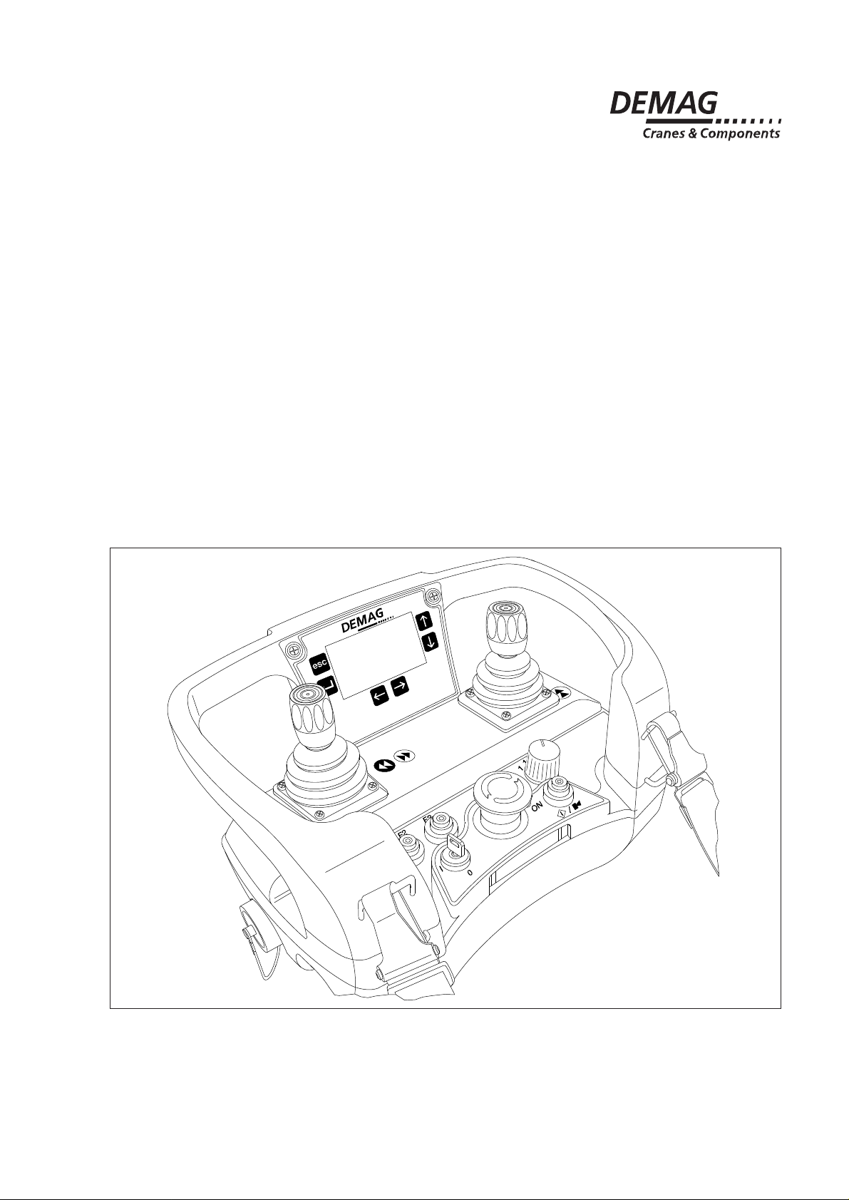
5 Identification and display functions
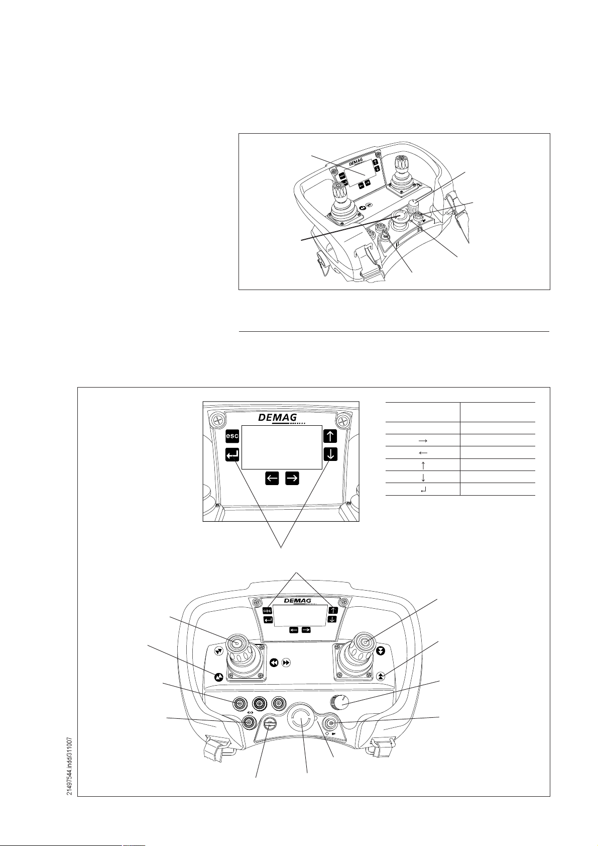
5.1 Joystick control unit
Display
STOP key
Travelling hoist
selector switch
Start / Horn key
LED
Key designation
Key-operated switch
42680844.eps
The LED in the joystick control system indicates the operating status of the joystick
control system:
LED Operating status
LED off The joystick control system is switched off or in standby
mode
LED lit red The joystick control system is in STOP mode
LED flashes green The joystick control system is in operating mode
Key
Symbol
Key
Designation
EscCancel
Right
Left
Up
Down
Return
42680944.eps
Yellow symbol against
black background
Joystick
Long travel forward/
backward
Cross travel left/right
Yellow symbol
against black
background
3 special function
keys (F1, F2, F3)
1 key
Check limit switches
Úï Úî Úí
Key-operated switch
Switching on and off
Joystick
Lift/lower load
Black symbol
against yellow background
3-stage travelling
ïõî
ï
î
hoist selector switch
(1 or 1+2 or 2)
×
ð
ÑÒ
×
ñ
1 key
Horn / Start
(Switching on the
joystick control unit)
Red/green LED
STOP key
42684444.eps
15
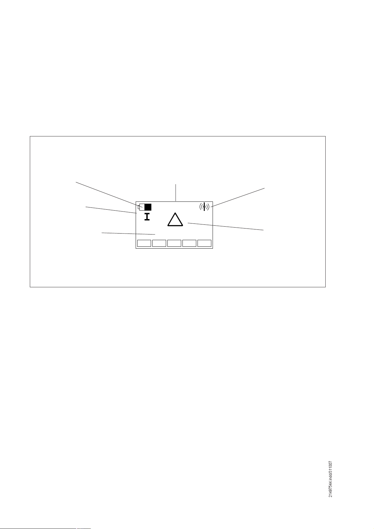
5.2 LCD display
DRC-MP radio receiver display
The joystick control unit is provided with a display. In the display, all data important
for operation of the crane to be operated are shown.
The number of information items displayed varies depending on the type of receiver. The scope of display functions comprises the general displays which are
available for both receiver types and additional information that can only be used
with DRC-DR receivers.
Battery capacity
Display of selected
travelling hoist(s)
2nd main row with alphanumerical display
Crane identification
Õëêì
ðððë
Radio signal quality
1st main row with
large icon or numerical
display
42694944.eps
16
 Loading...