

Scan Optics SO5000 User Manual

SO-5000 Ophthalmic Microscope User Manual Page 1 of 36
CONTENTS
INTRODUCTION .................................................................................................................... 3
PARTS LIST .................................................................................................................... 4
ASSEMBLY INSTRUCTIONS ............................................................................................ 5
Floor stand ........................................................................................................ 5
Microscope ........................................................................................................ 7
Connecting to a power source ................................................................................ 10
Battery operation, maintenance and safety ........................................................ 11
Foot controls ........................................................................................................ 11
Binocu lar assistant microscope ................................................................................ 12
USING THE MICROSCOPE ............................................................................................ 13
Articulated arm ........................................................................................................ 13
Panel controls ........................................................................................................ 15
Lamphouse ........................................................................................................ 16
Positioning the microscope ................................................................................ 17
Foot controls ........................................................................................................ 18
Sterilisation ........................................................................................................ 19
CARE AND MAINTENANCE ............................................................................................ 20
Care of the optical head............................................................................................ 20
Care of the main lamp ............................................................................................ 20
Main lamp replacement ............................................................................................ 21
Auxiliary lamp replacement ................................................................................ 22
Focus friction ........................................................................................................ 23
Power supply ........................................................................................................ 24
Power focus and zoom ............................................................................................ 24
Mould pellet replacement ..................................................................................... 25
INSTALLING CAMERA EQUIPMENT ................................................................................ 27
Video camera and monitor ................................................................................ 27
Attaching the camera adapter ................................................................................ 29
Disassembling the camera adapter .................................................................... 29
TROUBLESHOOTING ........................................................................................................ 31
SPECIFICATIONS ........................................................................................................ 33
Optical head ........................................................................................................ 33
Illuminat ion ........................................................................................................ 33
Power supply ........................................................................................................ 34
Mounting system ............................................................................................ 34
Foot controls ........................................................................................................ 34
Case .................................................................................................................... 34
SO-1370 Camera ............................................................................................ 35
SO-1380 Monitor ............................................................................................ 36
ISSUE NUMBER: 5.0
DATE: 11/04/02
SUPERSEDES: 4.0
DATE: 22/05/01
WRITTEN BY: RJK
DATE: 22/08/97
CHECKED BY: NW
DATE: 22/08/97

SO-5000 Ophthalmic Microscope User Manual Page 2 of 36
LIST OF FIGURES
Figure 1 Assembling the floor stand ................................................................. 5
Figure 2 Fixing the floor stand ............................................................................. 6
Figure 3 Attaching the clamp to a mounting surface ......................................... 7
Figure 4 Assembling the microscope ................................................................. 8
Figure 5 Inserting the eyepieces and sterilisable covers ......................................... 9
Figure 6 Connecting power cables and foot controls ......................................... 10
Figure 7 Binocular assistant microscope ................................................................. 12
Figure 8 Adjusting the articulated arm ................................................................. 13
Figure 9 Setting the power supply ................................................................. 15
Figure 10 Using the foot controls ................................................................. 18
Figure 11 Changing the main lamp ............................................................................. 21
Figure 12 Changing the auxiliary lamp ................................................................. 22
Figure 13 Adjusting focus friction ................................................................. 23
Figure 14 Mould pellet replacement ................................................................. 26
Figure 15 Video system schematic ....................................................................... 28
Figure 16 Assembl ing the 35mm camera attachments ......................................... 30
ISSUE NUMBER: 5.0
DATE: 11/04/02
SUPERSEDES: 4.0
DATE: 22/05/01
WRITTEN BY: RJK
DATE: 22/08/97
CHECKED BY: NW
DATE: 22/08/97

SO-5000 Ophthalmic Microscope User Manual Page 3 of 36
INTRODUCTION
Please read the following information carefully before installing and using the Scan Optics Ophthalmic
microscope. Scan Optics is responsible for the safety, reliability and performance of the equipment
only if it is used in accordance with these instructions.
This microscope is designed for use by a certified practitioner, for magnified observation of patients,
and for use in an operating theatre as an observation aid during surgery. A sample of this product has
tested as compliant to IEC 60601-1 for use at 110V and 200-260V, 10-40°C, and 60-95% relative
humidity.
Environmental storage and packing conditions of 60-95% relative humidity and 10-40 °C, are
recommended for this product.
No parts or accessories supplied with this microscope are supplied in a sterile condition.
Apart from those instructions within this manual, there are no user-serviceable parts in this
microscope. Scan Optics will retain the discretion to advise whether any repairs may be taken out by
external qualified technical personnel, or whether part(s) of the microscope must be returned to the
manufacturer’s premises for service or repairs to be carried out under warranty or otherwise. Where
appropriately qualified technical personnel are identified by a user, and ratified by Scan Optics, then
Scan Optics will make available on request any information which will assist in repairing the
equipment.
ISSUE NUMBER: 5.0
DATE: 11/04/02
SUPERSEDES: 4.0
DATE: 22/05/01
WRITTEN BY: RJK
DATE: 22/08/97
CHECKED BY: NW
DATE: 22/08/97

SO-5000 Ophthalmic Microscope User Manual Page 4 of 36
PARTS LIST
MAIN ASSEMBLIES
Clamp Assembly (includes power supply, clamp/pillar with pilla r safety
clamp)
Articulated Arm Assembly (includes horizontal arm and adjustable pantograph arm)
Microscope Assembly (includes tilt adjuster, microscope head, guide handle,
lamphouse, auxiliary light, universal arm and cable)
Foot Control (includes built-in cable for attachment to the power supply)
CABLES
12V dc Supply (Battery) Cable
OTHER
Focus Knob Sterilisable Covers (2)
Zoom Knob Sterilisable Covers (2)
Guide Handle Sterilisable Covers (2)
TOOL KIT
Eyepieces (2)
Spare Main Lamp (1)
Spare Auxiliary Lamp (1)
Socket keys (set 8: 1 x 1.5mm, 1 x 2mm, 1 x 2.5mm, 1 x 3mm, 2 x 4mm, 1 x 5mm, 1 x 6mm)
Lens Cloth
(OPTIONAL) FLOOR STAND
Base (1)
Pillar (1)
Clamp mount (1)
OPTIONAL ACCESSORIES SCAN OPTICS PART NU MBER
Binocula r Assistant Microscope SO-1420
Table Plate SO-291
Complete Coa xial Video SystemSO-1350
Coaxial Digital Camera and Printer SO-1355
35 mm Coaxial Camera SO-1375
ISSUE NUMBER: 5.0
DATE: 11/04/02
SUPERSEDES: 4.0
DATE: 22/05/01
WRITTEN BY: RJK
DATE: 22/08/97
CHECKED BY: NW
DATE: 22/08/97
SO-5000 Ophthalmic Microscope User Manual Page 5 of 36
ASSEMBLY INSTRUCTIONS
FLOOR STAND
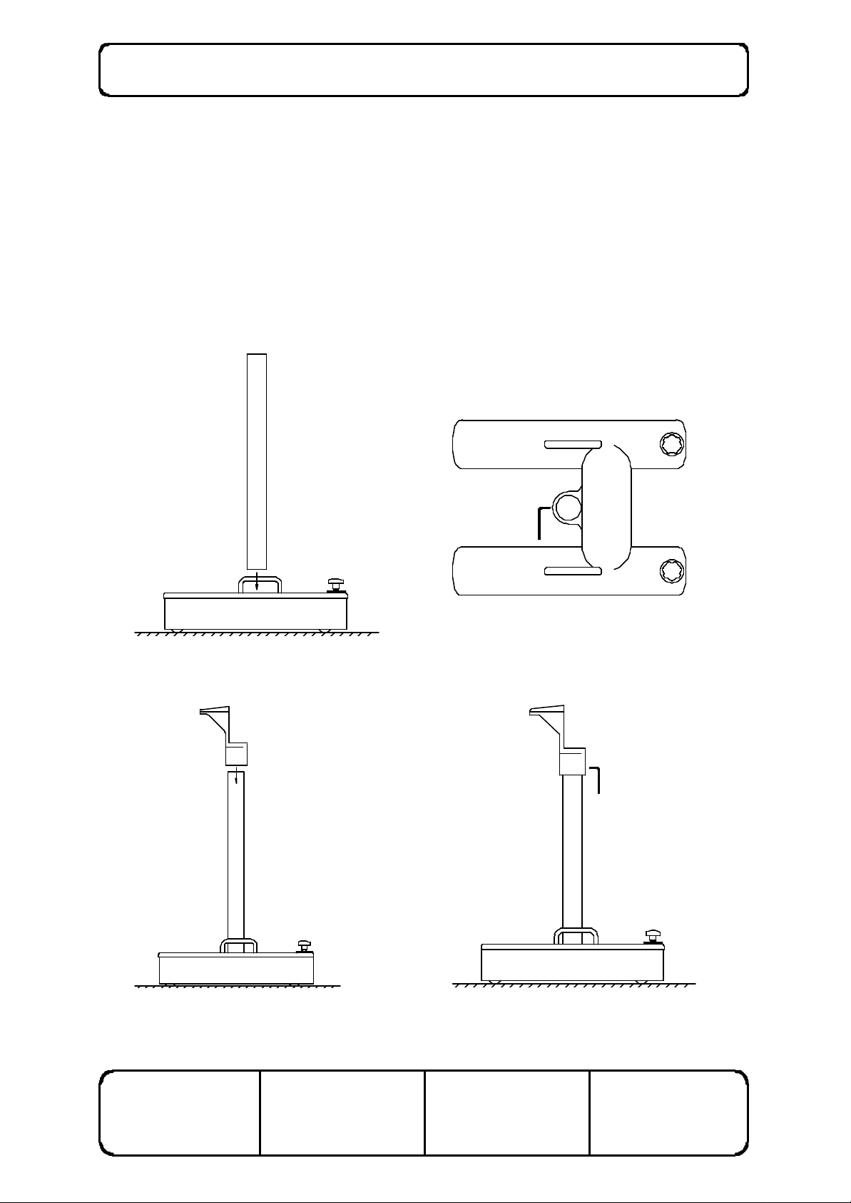
1. Remove the pillar, base and clamp mount from the case or carton.
2. Insert the pillar into the hole. Tighten the two grubscrews using the 5mm socket key found in
the tool kit to fix the pillar in place. Refer to figure 1 (A), (B).
3. Remove the clamp mount from the case or carton and place it on the pillar. Tighten the two
grubscrews to fix the clamp mount in place. Refer to figure 1 (C), (D).
A B
C D
Figure 1 Assembling the floor stand
ISSUE NUMBER: 5.0
DATE: 11/04/02
SUPERSEDES: 4.0
DATE: 22/05/01
WRITTEN BY: RJK
DATE: 22/08/97
CHECKED BY: NW
DATE: 22/08/97

SO-5000 Ophthalmic Microscope User Manual Page 6 of 36
4. To fix the floor stand, screw the knobs down until the stops are resting evenly on the floor.
Refer to figure 2.
5. Screw the knurled dis cs down on to the floor stand base to lock the stops. Refer to figure 2.
6. To unlock the floor stand, screw the knurled discs back up, then unscrew the knobs until the
wheels can move freely.
ISSUE NUMBER: 5.0
DATE: 11/04/02
Figure 2 Fixing the floor stand
SUPERSEDES: 4.0
DATE: 22/05/01
WRITTEN BY: RJK
DATE: 22/08/97
CHECKED BY: NW
DATE: 22/08/97
SO-5000 Ophthalmic Microscope User Manual Page 7 of 36
MICROSCOPE
1. Remove the clamp assembly from the case.
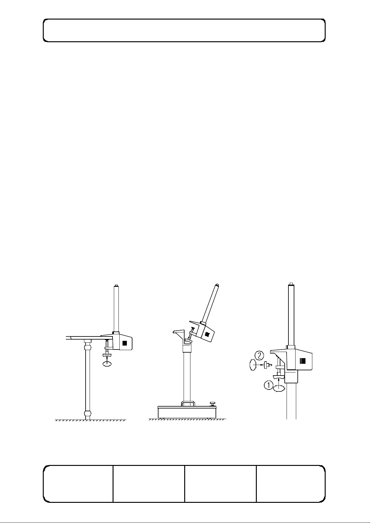
2. Fix the clamp to the operating table about 40 cm from the head of the table. The clamp may
be fixed on either side of the table. Make sure that the clamp is pressed firmly against the
side of the table before tightening. Refer to figure 3 (A).
M Alternatively, the clamp may be mounted on any horizontal surface that can
be positioned within 60 cm of the working position, such as a mobile trolley.
M The clamp may also be attached to the floor stand. When attaching to the
floor stand, first remove the two knobs from the clamp then tilt the clamp
backwards slightly to allow it to fit through the hole in the clamp mount.
Refer to figure 3 (B).
M The floor stand is clamped vertically to the main clamp assembly at one point
and at two points horizontally. First tighten the vertical clamp firmly then use
the two knobs provided to fix the clamp horizontally to the clamp mount.
Refer to figure 3 (C).
M It is important that the mounting surface be free from vibration and
movement. Note that in cases where the mounting surface is not rigid,
over-tightening of the vertical clamp will not improve microscope stability. In
this case, add a stiffening plate (such as Scan Optics Table Plate; Cat No.
SO-291) beneath the mounting surface and apply the clamp over the
stiffening plate and the original mounting surface..
A B C
ISSUE NUMBER: 5.0
DATE: 11/04/02
Figure 3 Attaching the clamp to a mounting surface
SUPERSEDES: 4.0
DATE: 22/05/01
WRITTEN BY: RJK
DATE: 22/08/97
CHECKED BY: NW
DATE: 22/08/97
SO-5000 Ophthalmic Microscope User Manual Page 8 of 36
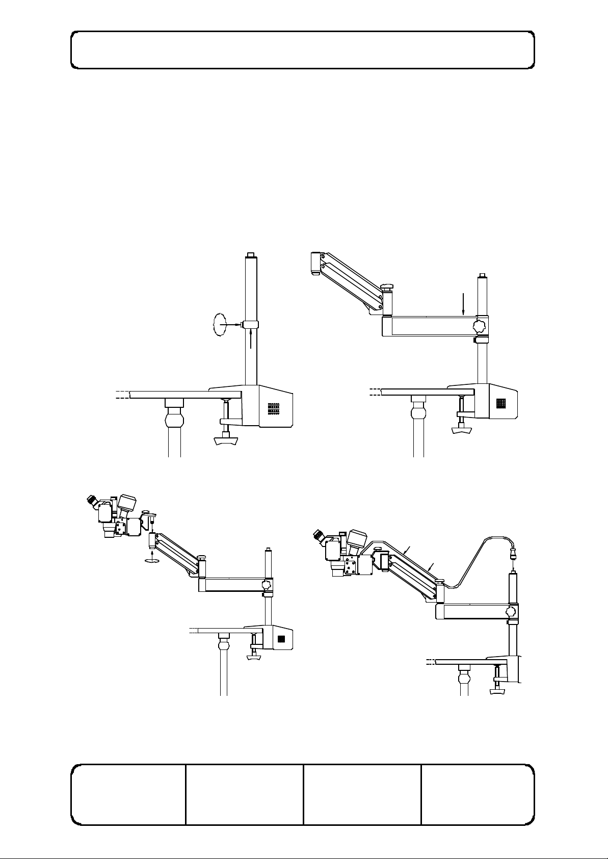
3. Tighten the pillar safety clamp at a point midway up the vertical pillar. Refer to figure 4 (A).
4. Remove the articulated arm assembly from the case, and place it on the vertical pillar. Make
sure that the arm assembly rests against the pillar safety clamp. Refer to figure 4 (B).
5. Remove the microscope assembly from the case and locate the microscope assembly in the
end of the arm assembly. Tighten the knob underneath the end of the arm to secure the
microscope in the collet. Refer to figure 4 (C).
7. Pass the lamphouse cable through the cable clips ring on the arm assembly and attach the plug
to the connector on the top of the pillar. This will ensure the cable does not obstruct the
surgeon or come into contact with the sterile area.
A B
C D
Figure 4 Assembling the microscope
ISSUE NUMBER: 5.0
DATE: 11/04/02
SUPERSEDES: 4.0
DATE: 22/05/01
WRITTEN BY: RJK
DATE: 22/08/97
CHECKED BY: NW
DATE: 22/08/97
SO-5000 Ophthalmic Microscope User Manual Page 9 of 36
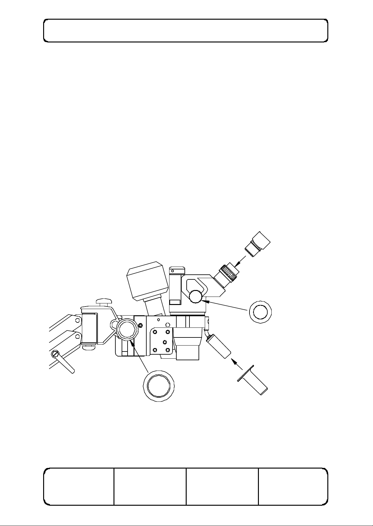
8. Remove the microscope eyepiece blanks and insert the eyepieces from the tool kit. Refer to
figure 5.
M Retain the eyepiece blanks in the tool kit for repacking the microscope. Do
not discard the eyepiece blanks.
M Take care to protect the Lamphouse prism at all times. If placing the
Microscope Assembly on a bench, lie carefully on one side.
9. Connect the zoom power cable to the socket on the side of the zoom drive cover.
10.. Remove the focus control knob cover and (small) zoom control knob cover from the bag inside
the case. Refer to figure 5. Push them into position on to the knobs on the left side of the
microscope head.
11. Remove the guide handle cover from the bag inside the case, and slide it over the guide handle
located at the front of the microscope. Refer to figure 5.
M The guide handle may be used to manoeuvre the microscope during surgery.
M All covers are intended to be sterilised before any operating procedures.
Figure 5 Inserting the eyepieces and sterilisable covers
ISSUE NUMBER: 5.0
DATE: 11/04/02
SUPERSEDES: 4.0
DATE: 22/05/01
WRITTEN BY: RJK
DATE: 22/08/97
CHECKED BY: NW
DATE: 22/08/97
SO-5000 Ophthalmic Microscope User Manual Page 10 of 36
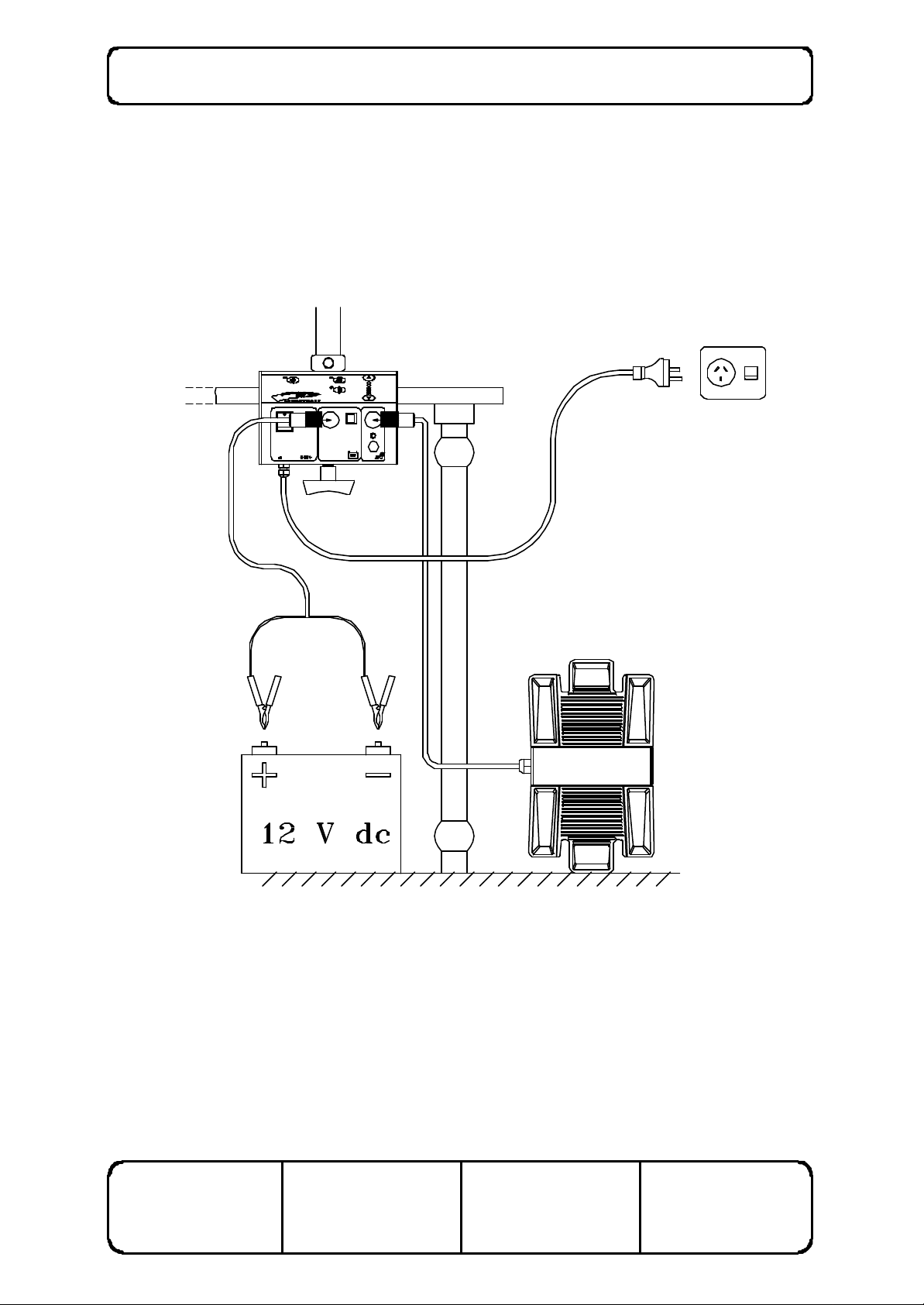
CONNECTING TO A POWER SOURCE
The Scan Optics Ophthalmic Microscope may be connected to either an earthed mains (90-260V) ac
supply, or a 12V dc supply, or both. The power supply will automatically select the correct mains
voltage. If both ac and dc supplies are connected, the dc supply (for example , a 12V battery) will act
as an emergency backup for mains power. In this case, the microscope will not run from battery
power unless the mains supply fails or falls by more than 20 percent, or is switched off. If mains
power is restored, the microscope will resume using mains power automatically. The mains power
switch on the microscope does not switch the battery off. Refer to figure 6.
ISSUE NUMBER: 5.0
DATE: 11/04/02
Figure 6 Connecting power cables and foot controls
SUPERSEDES: 4.0
DATE: 22/05/01
WRITTEN BY: RJK
DATE: 22/08/97
CHECKED BY: NW
DATE: 22/08/97

SO-5000 Ophthalmic Microscope User Manual Page 11 of 36
1. Plug the mains power cable into a mains power socket. International safety standards do not
allow the use of an extension cord.
M The mains power supply must have a protective earth conductor. If
there in no earth conductor, or if the integrity of the earth conductor
arrangement is in doubt, the equipment must be operated from a 12Vdc
power source.
2. Switch on the mains power supply at the wall socket.
M When the ON/OFF switch is selected to ON, the power supply indicator on
the switch will light and an audible 'beep' should be heard.
BATTERY OPERATION, MAINTENANCE AND SAFETY
Scan Optics recommend the use of sealed rechargeable lead-acid 12V batteries such as Scan Optics
Cat Nos. SO-251 (small, light, lower (7Ah) capacity) and SO-9210 (large, heavy, higher (35Ah)
capacity). These batteries are maintenance-free and can be operated, charged or stored in any
position without leakage.
1. If the power supply is to be connected to a 12-volt dc supply, remove the battery cable from
the case and connect the cable to the 12-volt connector on middle of the front panel on the
power supply. Refer to figure 6.
2. Connect the red battery clip to the positive battery terminal, and the black clip to the negative
battery terminal. The power supply will not operate if the terminals are reversed
M Earthing is not required when a 12-volt supply is used alone.
M The 12 volt supply must be direct current. The power supply will not operate
with 12 volts alternating current.
Caution:
M Do not charge these batteries in a sealed container.
M Avoid short-circuiting batteries.
M Old lead-acid batteries of any type must be disposed of correctly. It is
recommended that they are recycled by an appropriate establishment who
recycle car batteries. Lead acid batteries should not be disposed of with
ordinary waste, as lead poisoning or acid trauma may result.
Where battery backup is used, Scan Optics recommend a periodical check of the battery to
ensure it is charged and functional.
FOOT CONTROLS
1. Remove the foot control from the case and plug the cable into the socket on the right side of
the front panel of the power supply. Refer to figure 6.
2. Check that the cable from the housing in front of the microscope is connected to the socket on
the side of the rectangular zoom drive housing on the right side of the microscope head.
ISSUE NUMBER: 5.0
DATE: 11/04/02
SUPERSEDES: 4.0
DATE: 22/05/01
WRITTEN BY: RJK
DATE: 22/08/97
CHECKED BY: NW
DATE: 22/08/97
SO-5000 Ophthalmic Microscope User Manual Page 12 of 36
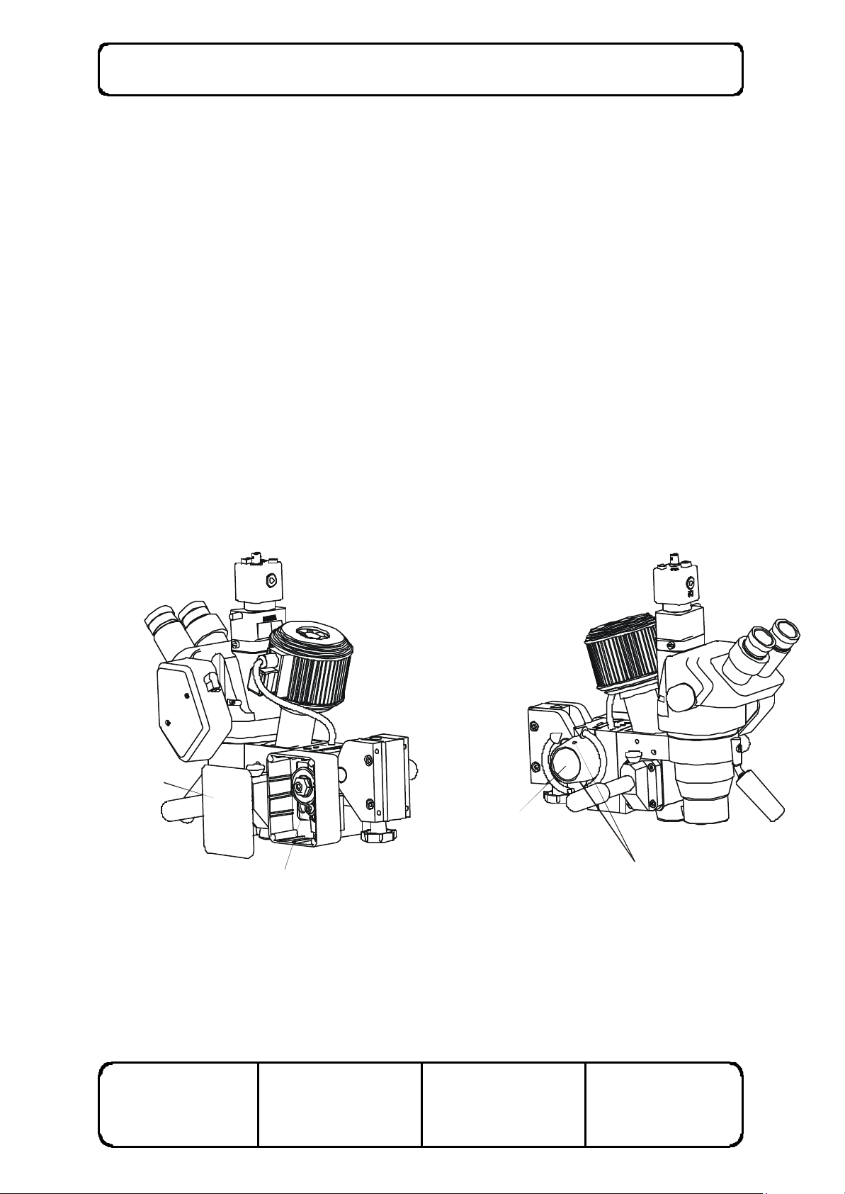
FOCUS
KNOBS
MICROSCOPE
ANGLE
MOUNT
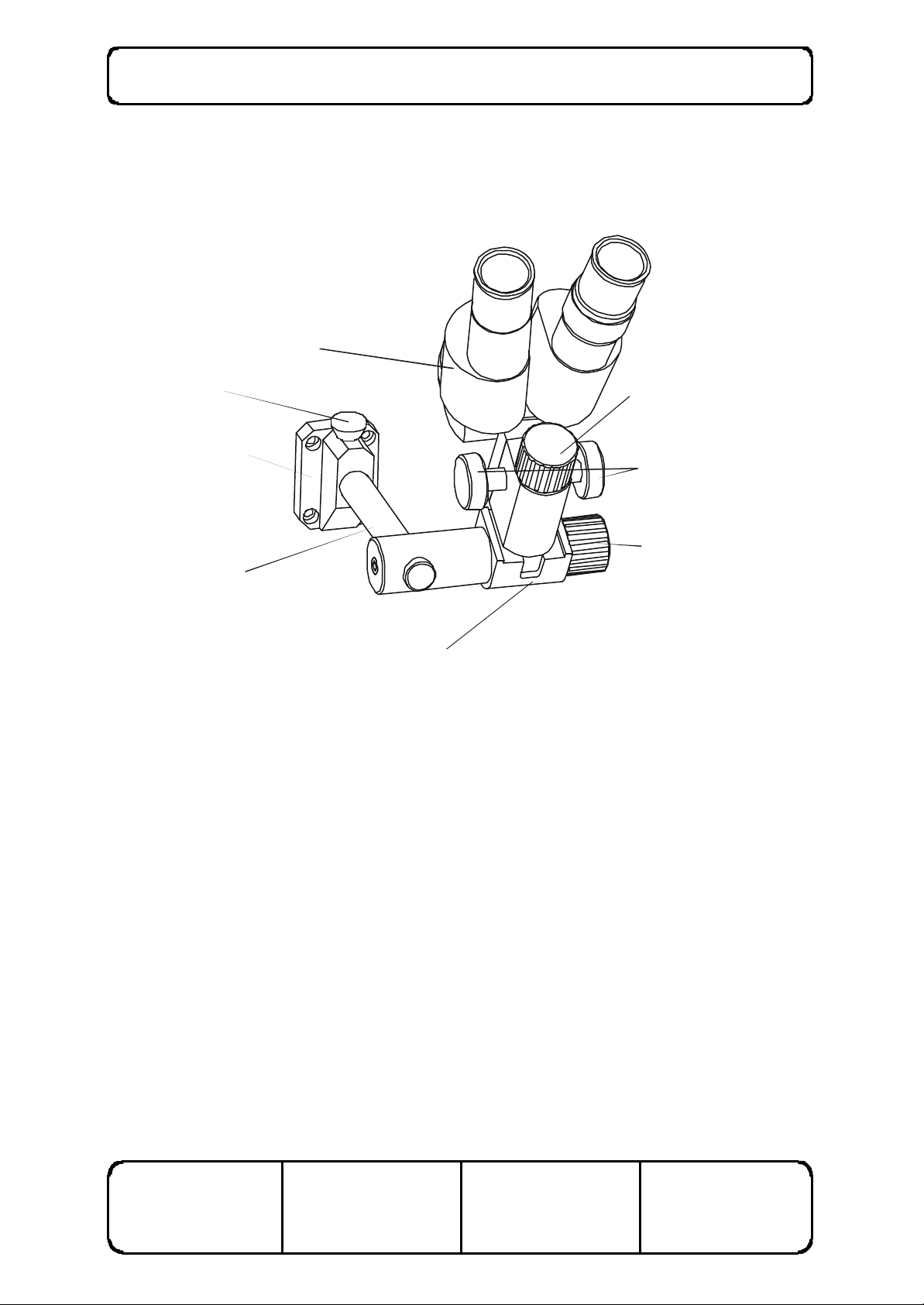
BINOCULAR ASSISTANT MICROSCOPE
The optional assistant microscope allows an observer to view procedures under magnification within
close proximity of the operating field. To attach the microscope, insert the mounting arm in to the mounting
bracket and then insert the locking pin.
MICROSCOPE
HEAD
LOCKING PIN
LOCK KNOB
MOUNTING
BRACKET
LOCK KNOB
MOUNTING ARM
MICROSCOPE
Figure 7 Binocular assistant microscope
Sterilisable covers are provided to fit over the focus knobs.
Pupillary distance adjustment is performed manually, but the eyepieces are not geared together. For
the best user comfort, ensure that the eyepieces are equidistant from the central axis of the main
optical path.
The adjustable eyepiece may be used to compensate for any refractive error difference between the
left and right eye of the user. First, rotate the adjustable (left) eyepiece so that there are equal
amounts of adjustment on either side. Then focus the microscope while closing the left eye and
looking only through the right eyepiece. When the microscope is focussed, close the right eye and look
with the left eye through the left eyepiece, and rotate the adjusting ring until the left eye is focussed.
When the microscope is fitted to the side of the main microscope head, a tilt angle of approximately 30
degrees will enable the visual field of the assistant microscope to match that of the main microscope
head. To adjust this angle, loosen the angle lock knob while holding the microscope head, tilt the head
to the appropriate angle and lock it again. Small sideways adjustments of the visual field can be
achieved by loosening the microscope lock knob and rotating the microscope head about its mounting
axis. When the fields are aligned correctly, tighten the microscope lock knob once again.
ISSUE NUMBER: 5.0
DATE: 11/04/02
SUPERSEDES: 4.0
DATE: 22/05/01
WRITTEN BY: RJK
DATE: 22/08/97
CHECKED BY: NW
DATE: 22/08/97

SO-5000 Ophthalmic Microscope User Manual Page 13 of 36
US ING THE MICROSCOPE
ARTICULATED ARM
The articulated arm includes a number of features which enable the microscope to be adjusted in
almost any position. Refer to figure 8.
Figure 8 Adjusting the articulated arm
1. The horizontal arm may rotate about the vertical pillar by unlocking the pillar lock knob (A).
To prevent the arm from rotating, simply lock the knob.
2. The pantograph (moving) arm may rotate about the end of the horizontal arm by unlocking the
elbow lock knob (B). To prevent the arm from rotating, simply lock the knob.
3. The amount of force required to move the pantograph arm up and down may be adjusted by
rotating the screw lo cated at the top of the elbow joint, indicated at point (C). To adjust the
screw, first move the pantograph arm down to reveal the screw through the slot in the top of
the arm. Use the large hexagonal key located in the toolbox to rotate the screw. To decrease
the amount of force required to move the arm, rotate the screw clockwise. To increase the
amount of force required to move the arm, rotate the screw anticlockwise. When the screw
is adjusted to its limit, rotate the screw half a turn in the opposite direction to ensure the arm
continues to operate smoothly
4. The amount of friction in the pantograph arm may be adjusted by rotating the handle (D)
located on the side of the pantograph arm. The arm may thus be locked in any position or
alternatively, the amount of friction can be set so that the arm is stable but will move when a
force is applied.
ISSUE NUMBER: 5.0
DATE: 11/04/02
SUPERSEDES: 4.0
DATE: 22/05/01
WRITTEN BY: RJK
DATE: 22/08/97
CHECKED BY: NW
DATE: 22/08/97

SO-5000 Ophthalmic Microscope User Manual Page 14 of 36
5. The knob (E) located on the underneath side of the end of the pantograph arm is used to lock
the microscope assembly into place. To release the microscope assembly, simply unscrew the
knob and lift the assembly carefully out of the collet
6. The microscope head may be tilted up and down by rotating the knob (F). The microscope
may be tilted into position between -45â and +5â. To tilt the head down, rotate the knob in the
clockwise direction.. To tilt the head up, rotate the knob anticlockwise.
7. The optional guide handle (G) may be used to manoeuvre the microscope once the appropriate
friction has been set on the othe r knobs.
ISSUE NUMBER: 5.0
DATE: 11/04/02
SUPERSEDES: 4.0
DATE: 22/05/01
WRITTEN BY: RJK
DATE: 22/08/97
CHECKED BY: NW
DATE: 22/08/97
SO-5000 Ophthalmic Microscope User Manual Page 15 of 36
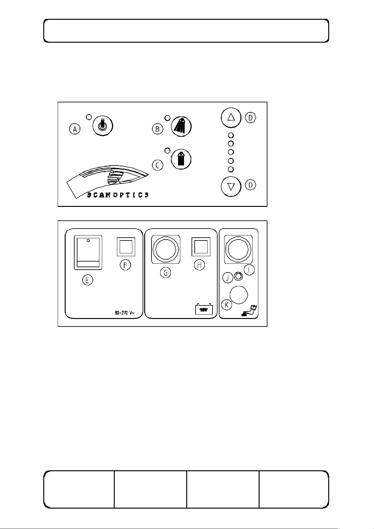
PANEL CONTROLS
The panel on the SO-5000 clamp/power supply unit controls the main (coaxial) and auxiliary lights, the
powered focus and zoom speeds, and provides an interface for connections to the foot control and
battery. Refer to figure 9.
Figure 9 Setting the power supply
Power Supply - key to symbols
A Standby button/indicator F Resettable circuit breaker (mains side)
B Auxiliary light button/indicator G Battery cable panel plug
C Main light button/indicator H Resettable circuit breaker (battery side)
D Intensity button/indicator I Foot control input socket
E Main switch J Foot control indicator
K Power focus/zoom speed control
ISSUE NUMBER: 5.0
DATE: 11/04/02
SUPERSEDES: 4.0
DATE: 22/05/01
WRITTEN BY: RJK
DATE: 22/08/97
CHECKED BY: NW
DATE: 22/08/97

SO-5000 Ophthalmic Microscope User Manual Page 16 of 36
1. The power supply is switched on by depressing the switch (E) on the front panel. When the
power supply is switched on, the indicator on the switch and the indicator ne xt to the button
(A) on the top panel will light up and an audible 'beep' will be heard. The main switch also
activates cooling fans located in the power supply and in the lamphouse.
2. When the power supply is switched on, the unit automatically starts on 'standby' mode, as
indicated by the light next to the button (A) on the front panel. In order to activate the power
supply, depress the button (A) a single time. The indicator light will turn off and a single 'beep'
will be heard. The power supply is now ready to operate.
3. To switch on the main (coa xial) light, press the button (C) on the top panel. To switch on the
auxiliary light, press the button (B) on the top panel.
4. The intensity of the main and auxiliary light may be varied by selecting the up or down arrow
intensity selection button (D) on the top panel. There are five intensity settings. In the event
that the power supply is switched off or placed on standby, the intensity will revert to the
previous setting when the power supply is switched back on.
5. A 12V ba ttery may be connected to the power supply as a backup for mains or as an
alternative to the mains supply. To connect a battery, place the crocodile clips on the battery
cable to the appropriate terminals on the battery (red positive +, black negative -) and connect
the battery cable to the panel plug (G) on the front panel.
6. The foot control may be connected to the front panel by inserting the plug on the end of the
foot control cable into the socket (I) on the front panel. When a pedal on the foot control is
depressed, the indicator (J) on the front panel will light up. This indicates that the foot control
is connected and working properly. To increase the speed of the power focus and zoom
which are activated by the foot controls, turn the speed control (K) on the front panel in the
anticlockwise direction. To decrease the speed of the power focus and zoom, turn the knob
clockwise.
7. In the event that the power supply fails due to a supply variation, the power supply can be
reactivated with the resettable circuit breakers (F) and (H) on the front panel of the power
supply.
LAMPHOUSE
1. The lamphouse on the SO-5000 ophthalmic microscope produces a coaxial light which
provides a red fundus reflex from the back of the eye. The intensity of the light may be
controlled from the top panel of the power supply or by using the optional foot controls.
2. The lamphouse position may be adjusted if the light patch is not exactly centred on the centre
of the image viewed through the eyepieces. To centre the light patch, adjust the angle of the
lamphouse by turning the socket screws (using the socket key provided in the tool box) in the
plate fixed to the microscope holder. When winding the socket screw in on one side, wind the
socket screw on the other side an equivalent amount in the opposite direction to ensure that
the lamphouse is held firmly in place. A small amount of adjustment of the two screws should
be sufficient to adequately centre the light patch.
ISSUE NUMBER: 5.0
DATE: 11/04/02
SUPERSEDES: 4.0
DATE: 22/05/01
WRITTEN BY: RJK
DATE: 22/08/97
CHECKED BY: NW
DATE: 22/08/97

SO-5000 Ophthalmic Microscope User Manual Page 17 of 36
POSITIONING THE MICROSCOPE
Note that the equipment must be located more than 25 cm away from any medical gas system or
disinfection or degreasing system containing flammable vapour. The power supply must also be
protected from liquid splashes and spills.
1. Set the instrument approximately in position by swinging the elbow as required.
2. Set the focus adjustment to the midway position by rotating the focus knob appropriately.
3. Adjust the height of the microscope by moving the arm vertically so that the work area is
approximately in focus. Tighten the pillar and elbow lock knobs.
4. Check the eyepiece setting to ensure clear vision with each eye separately, and set the
pupillary distance. Note that the working distance is increased by rotating both eyepieces in a
clockwise direction, and reduced by rotating both eyepieces counter-clockwise.
5. The microscope can now be swung aside ready for use with a patient.
6. Swing the microscope over the patient
7. Hold the focus knob to move the microscope to the correct position. The most accurate
focusing can be obtained at the highest magnification, as the depth of focus is then minimised.
8. Tighten the pillar lock knob until the microscope is prevented from moving freely, but is still
able to be moved when required. The friction of the arm and elbow knobs should be adjusted
so that the movement feels uniform in all directions.
9. Focus and zoom knobs may be used to manually focus the microscope or manually set the
magnification level, even though a foot control is fitted.
10. To swing the microscope out of the way, unlock the pillar lock knob and swing the microscope
about the vertical pillar. It will remain in focus when returned to the work area.
ISSUE NUMBER: 5.0
DATE: 11/04/02
SUPERSEDES: 4.0
DATE: 22/05/01
WRITTEN BY: RJK
DATE: 22/08/97
CHECKED BY: NW
DATE: 22/08/97
SO-5000 Ophthalmic Microscope User Manual Page 18 of 36
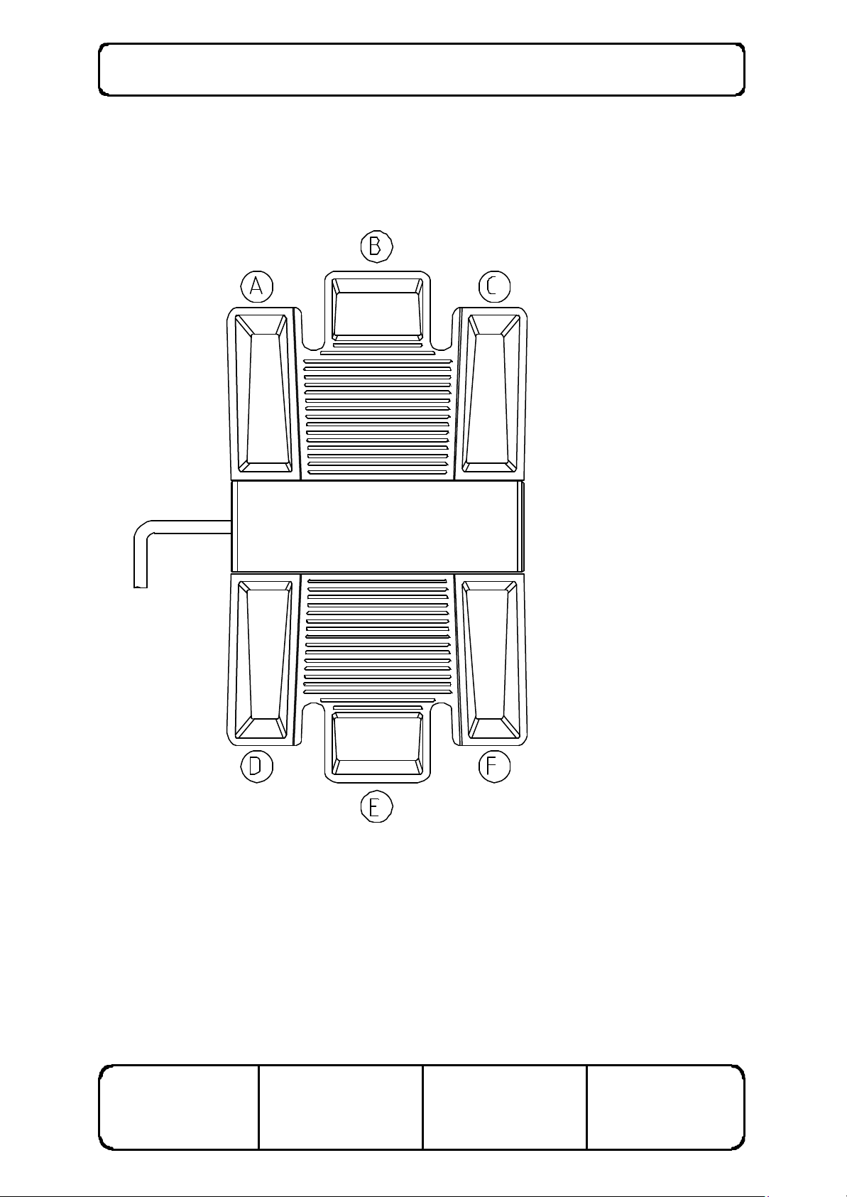
FOOT CONTROLS
1. The foot control enables the surgeon to focus the microscope, change the magnification level
and change the light intensity by depressing pedals, thus enabling both hands to be kept free
for surgery. Refer to figure 10.
Figure 10 Using the foot controls
2. The magnification level may be increased by depressing the pedal (A), and decreased using
the pedal (D). The drive system will stop automatically when the magnification has reached
its upper or lower limit.
3. The light intensity level may be increased by depressing the pedal may be increased by
depressing the pedal (B) and decreased using the pedal (E)
ISSUE NUMBER: 5.0
DATE: 11/04/02
SUPERSEDES: 4.0
DATE: 22/05/01
WRITTEN BY: RJK
DATE: 22/08/97
CHECKED BY: NW
DATE: 22/08/97

SO-5000 Ophthalmic Microscope User Manual Page 19 of 36
4. The microscope may be focused in the upward direction by depressing the pedal (C) and
focused downwards using the pedal (F). The drive system will stop automatically when the
focus has reached its upper or lower limit.
5. The rate of magnification change and the focus speed may be set by adjusting the knob on the
front panel of the power supply. Refer to figure 8. To increase the speed of the power focus
and zoom, turn the speed control (K) on the front panel in the clockwise direction. To
decrease the speed of the power focus and zoom, turn the knob anticlockwise.
NOTE: Do not attempt to use the foot pedal to focus or zoom the microscope at the same
time as using the manual focus or zoom knobs.
STERILISATION
1. All removeable knobs may be sterilised. However, it may be convenient for the clamp knobs
to be set by a non-sterile person.
2. The removeable knobs and covers may be sterilised by:
M boiling
M autoclaving
M chemical sterilisation
M gas sterilisation.
3. Before sterilising clamping knobs, first remove the plastic pad from the end of the shaft.
4. The anodised and plated metal components can be wiped with any of the normal disinfectants.
5. The plastic parts and the paintwork of the microscope assembly and the power supply may be
affected by organic solvents. Do not autoclave or wipe with organic solvents such as ether,
xylene or alcohol; to clean use water-based solvents only.
6. One set of covers can be sterilised while the other is in use.
NOTE: National authorities may require the use of specific sterilisation or disinfection
methods.
ISSUE NUMBER: 5.0
DATE: 11/04/02
SUPERSEDES: 4.0
DATE: 22/05/01
WRITTEN BY: RJK
DATE: 22/08/97
CHECKED BY: NW
DATE: 22/08/97

SO-5000 Ophthalmic Microscope User Manual Page 20 of 36
CARE AND MAINTENANCE
CARE OF THE OPTICAL HEAD
1. Cleaning the optical components.
The eyepieces should be checked for cleanliness each time the instrument is used. Surface
dust should be removed with a clean, soft brush. Fingerprints or grease may be removed by
lightly wiping with a cotton cloth or lens tissue moistened with a 70:30 mixture of absolute
alcohol (either ethanol or methanol) and ether. Do not use acetone as it may damage the
surface coating.
2. Cleaning the plastic parts and paintwork.
Use water based cleaners only.
Do not use any organic solvent such as alcohol, ether or xylene.
3. Protection against mould.
In hot and humid climates it is common for mould to grow on optical surfaces. Cleaning and
repairing the damage can be expensive and inconvenient. To minimise the risk of mould
forming, do not leave the instrument without either eyepieces or eyepiece blanks inserted and
always store the optical head in a sealed bag containing silica gel desiccant. In tropical
climates, routine annual maintenance of the optical head is recommended.
4. Do not dismantle.
No parts inside the optical head of the instrument can be serviced by the user. Attempts to
dismantle the optical head or prism cover will make any warranty void.
CARE OF THE MAIN LAMP
1. The main lamp supplied has a rated average life of 50 hours.
2. The actual life of the lamp will depend on the intensity setting normally used. The highest
setting is an over-run setting which increases light output but will reduce lamp life.
Conversely, running the lamp at the lowest setting will produce a lamp life of greater than 50
hours.
3. It is strongly recommended that the lamp be replaced as a routine maintenance task, to reduce
the possibility of failure during surgery.
ISSUE NUMBER: 5.0
DATE: 11/04/02
SUPERSEDES: 4.0
DATE: 22/05/01
WRITTEN BY: RJK
DATE: 22/08/97
CHECKED BY: NW
DATE: 22/08/97
SO-5000 Ophthalmic Microscope User Manual Page 21 of 36
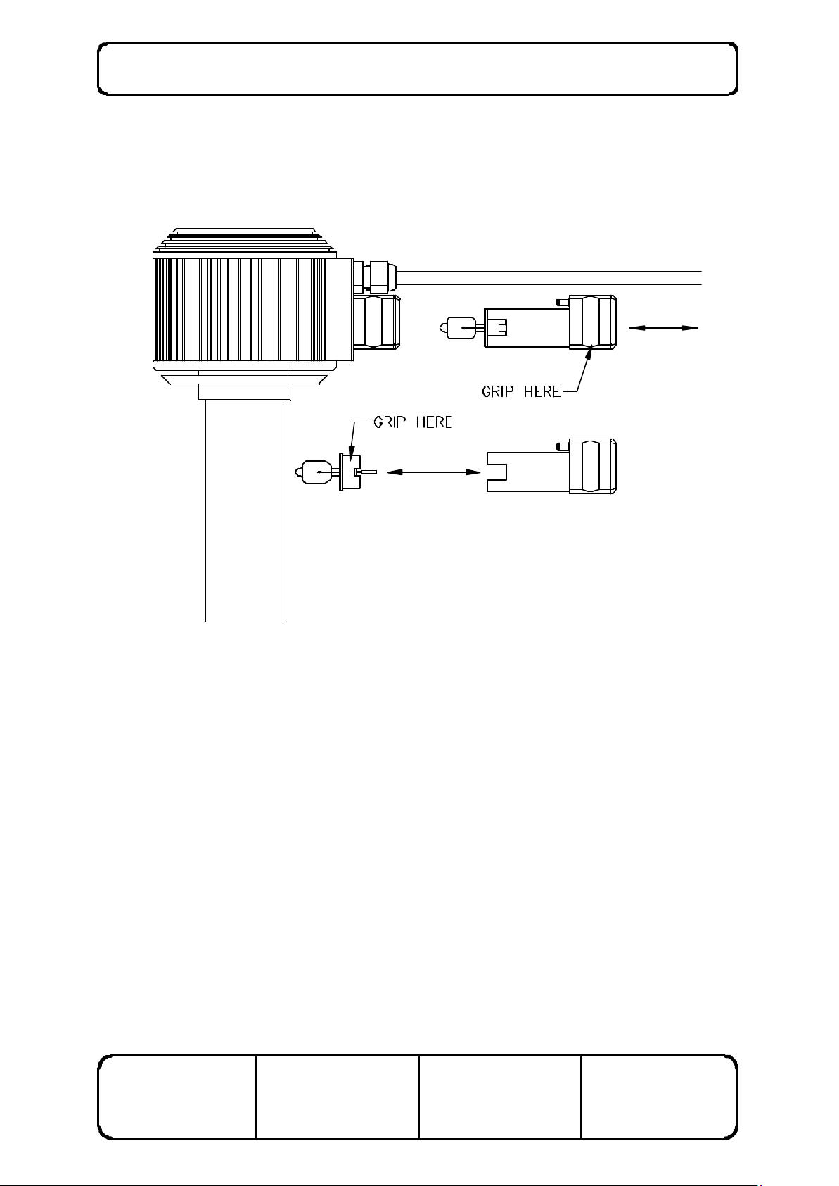
MAIN LAMP REPLACEMENT
1. Always use protective gloves while replacing the lamp as lamp temperatures may be
sufficiently high to burn skin should it come into contact with the glass capsule. Where
possible, allow the lamp to cool before replacing it.
Figure 11 Changing the main lamp
2. To replace the lamp, first grip the rectangular block located beneath the cable gland at the
back of the lamphouse. Pull the block outwards from the long rectangular block to reveal the
lamp assembly. Refer to figure 11.
3. Grip the lamp holder at the sides where the rectangular cutout is located, and pull the lamp out.
Do not attempt to pull the lamp out by gripping the glass capsule. Refer to figure 11.
4. Push the new lamp into the socket so that the lamp flange sits flush on the front of the locating
tube. Replace the lamp assembly in the long rectangular block, so that the pins engage in the
sockets and ‘click’ into place. Ensure that the new lamp is free of grease or finger prints
before replacement. Any such marks should be removed with a solvent such as methanol to
avoid reducing lamp life.
ISSUE NUMBER: 5.0
SUPERSEDES: 4.0
WRITTEN BY: RJK
CHECKED BY: NW
DATE: 11/04/02
DATE: 22/05/01
DATE: 22/08/97
DATE: 22/08/97
SO-5000 Ophthalmic Microscope User Manual Page 22 of 36
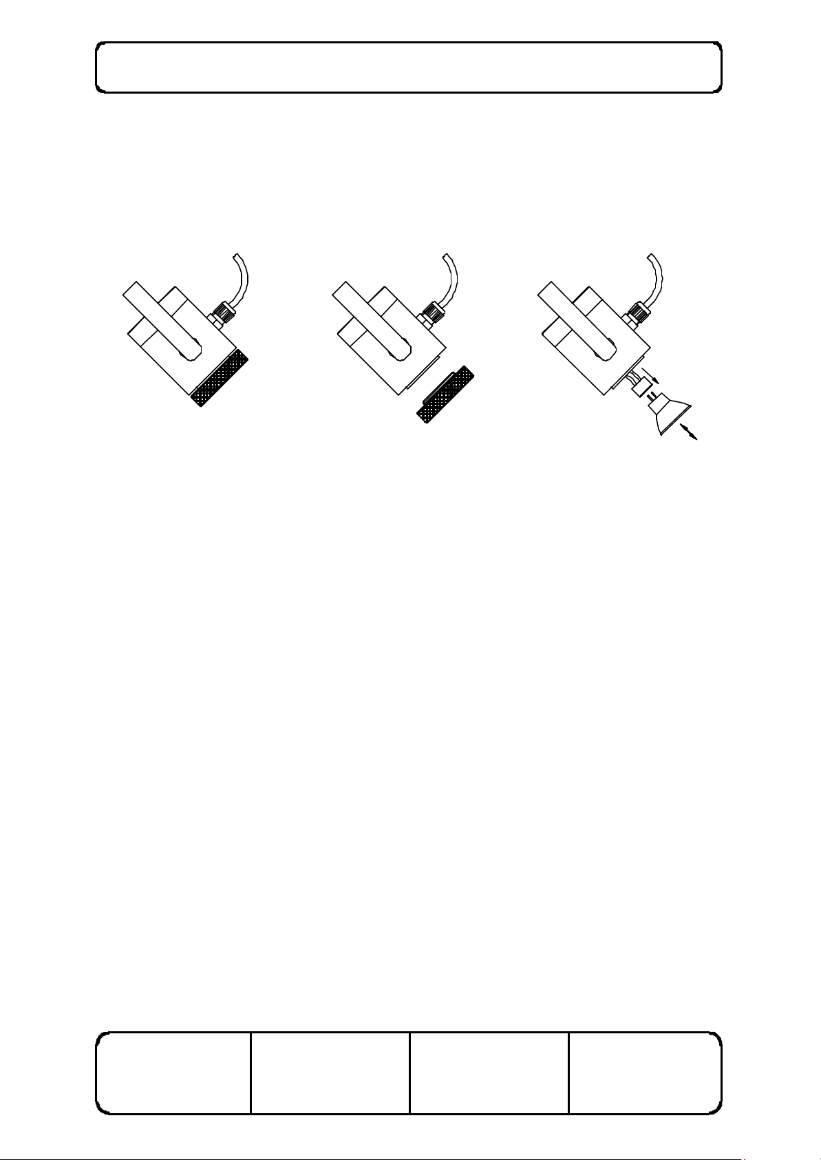
AUXILIARY LAMP REPLACEMENT
1. NOTE: The auxiliary light assembly and lamp may be extremely hot after extended
use. Use a cloth or protective glove to protect hands from the hot surfaces while
undertaking lamp maintenance or replacement if the lamp has been on recently.
Figure 12 Changing the auxiliary lamp
2. In the event of auxiliary lamp failure, first turn the auxiliary light off at the power supply .
4. Remove the protective filters by unscrewing the black ring at the front of the lamp barrel.
Refer to figure 12.
5. Push the cable which feeds into the hole in the back of the barrel until the lamp is exposed.
Remove the lamp by pulling it out of the socket. Replace the lamp with one of the same size
and rating.
6. Replace the filter ring by screwing it back into place.
7. Switch the auxiliary light back on at the power supply.
ISSUE NUMBER: 5.0
DATE: 11/04/02
SUPERSEDES: 4.0
DATE: 22/05/01
WRITTEN BY: RJK
DATE: 22/08/97
CHECKED BY: NW
DATE: 22/08/97
SO-5000 Ophthalmic Microscope User Manual Page 23 of 36
LOOSEN 2 x GRUB SCREWS
RE-TIGHTEN AFTER KNOB ADJUSTED
TIGHTEN OR
AS NECESSARY
FOCUS DRIVE COVER
GRIP LARGE DRIVE GEAR
FOCUS FRICTION
The SO-5000 microscope system relies on a friction device to allow the microscope head to stay in
position when it is not being focussed, yet still allow the head to be focussed manually or by the motor
drive. Over time or with extended use, the friction may decrease resulting in some slippage of the
microscope head focussing system. This is easily remedied by resetting the focus friction.
Firstly, focus the microscope all the way down to avoid the possibility of accidental slipping.
Remove the focus drive cover by removing the four screws. Identify the locations of the two holes
drilled transversely, 180 degrees apart through the manual focus knob on the other side. Insert a 2mm
socket key to loosen the grubscrews in each hole.
While gripping the large white gear steady in the focus drive housing (to ensure the gears do not strip),
tighten the knob to increase friction, or loosen it to decrease friction as necessary. When the
appropriate setting has been found, tighten the grubscrews again and replace the focus drive cover.
Note that there may be a small level of experimentation required to achieve the best friction setting. If
the motor drive becomes too slow, there is probably too much friction although first check that the
motor speed adjustment on the main panel is not set excessively low. If the focus system tends to slip,
especially at the top of the range, the amount of friction needs to be increased. In most cases a slight
increase in friction works best when the focus system is showing signs of slipping.
ISSUE NUMBER: 5.0
DATE: 11/04/02
LOOSEN KNOB
Figure 13 Adjusting focus friction
SUPERSEDES: 4.0
DATE: 22/05/01
WRITTEN BY: RJK
DATE: 22/08/97
CHECKED BY: NW
DATE: 22/08/97

SO-5000 Ophthalmic Microscope User Manual Page 24 of 36
POWER SUPPLY
1. In many countries the mains voltage fluctuates widely. Low voltage can greatly reduce the
light output, and high voltage can greatly reduce lamp life. The Scan Optics power supply
automatically provides a constant voltage to the lamp for a wide range of mains power
voltages.
2. The panel on the power supply may be cleaned by wiping it with a damp cloth. If necessary,
a mild detergent may be used. Do not use abrasive chemicals or agents such as acetone to
clean the panel, as these may damage the protective lexan coating.
POWER FOCUS AND ZOOM
If the manual knobs are used in preference to the foot controls for focussing and zooming, it
is recommended that the foot controls be disconnected, in order to reduce wear on the
power drive gears. Do not attempt to use the foot pedal to focus or zoom the microscope at
the same time as using the manual focus or zoom knobs.
ISSUE NUMBER: 5.0
DATE: 11/04/02
SUPERSEDES: 4.0
DATE: 22/05/01
WRITTEN BY: RJK
DATE: 22/08/97
CHECKED BY: NW
DATE: 22/08/97

SO-5000 Ophthalmic Microscope User Manual Page 25 of 36
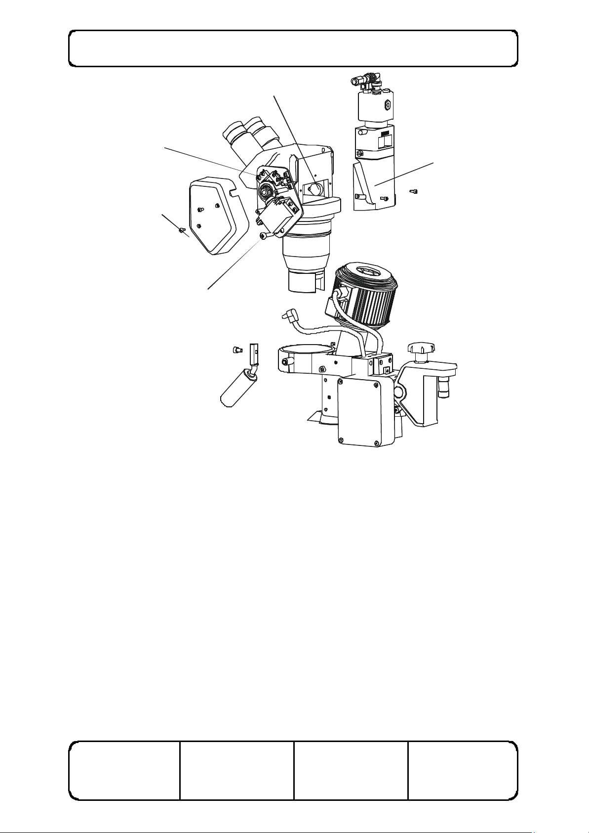
MOULD PELLET REPLACEMENT
The Scan Optics SO-5000 series microscopes are fitted with mould protection which lasts for
approximately 3 years, but will be dependent on the storage conditions and humidity of the local
environment. In extreme tropical climates it may be necessary to change the mould protection as
frequently as every year.
A guide to when the mould protection should be changed is placed on a sticker on the front of the
microscope head. However this is indicative only and users should be guided by their own experience
and knowledge of local conditions.
As a general precaution, always store the microscope head in a protective bag when not in use, and
replace the eyepieces with the protective eyepiece caps.
To replace the mould protection pellet, refer to figure 14. First disconnect the zoom power cable and
remove the zoom drive cover located on the right side of the microscope head. This will expose a
large Philips headed screw which fixes the zoom drive assembly to the microscope mounting bracket,
by means of a cylindrical spacer located behind the zoom drive plate. Loosen this screw and the
grubscrew located directly opposite, on the left side of the microscope head. This will allow the entire
microscope head to be lifted clear of its mounting bracket.
Place the microscope head down carefully, and remove the two screws that hold the back cover of
the microscope. Note that in microscopes not fitted with video accessories, the same procedure
should be followed, but only a single screw needs to be removed to undo the back cover. Remove the
back cover carefully, and locate the circular anti-mould pellet that is adhered to the inside of the
microscope head. Replace the pellet with a new one, peeling the back off to reveal the new adhesive.
Take care not to touch any internal optical components, as these are easily damaged and are difficult
to clean correctly if smudged by fingerprints or exposed to dirt of any kind.
Then replace the back cover of the microscope and place the assembly carefully back in its mounting
bracket. Fix the mounting screw through the cylindrical spacer and tighten it in to the thread in the
mounting bracket. Finally, tighten the remaining grubscrew to fix the microscope head back in place.
ISSUE NUMBER: 5.0
DATE: 11/04/02
SUPERSEDES: 4.0
DATE: 22/05/01
WRITTEN BY: RJK
DATE: 22/08/97
CHECKED BY: NW
DATE: 22/08/97
SO-5000 Ophthalmic Microscope User Manual Page 26 of 36
BACK COVER
REPLACE ANTI-MOULD
PELLET
ZOOM ASSEMBLY
ZOOM COVER
MOUNTING SCREW
ISSUE NUMBER: 5.0
DATE: 11/04/02
Figure 14 Mould pellet replacement
SUPERSEDES: 4.0
DATE: 22/05/01
WRITTEN BY: RJK
DATE: 22/08/97
CHECKED BY: NW
DATE: 22/08/97

SO-5000 Ophthalmic Microscope User Manual Page 27 of 36
INSTALLING CAMERA EQUIPMENT
VIDEO CAMERA AND MONITOR
1. Set up the microscope according to the instructions.
2. Slide the second safety clamp on to the pillar and tighten lock.
3. Slide the mounting arm onto the pillar and rest on top of the safety clamp.
4. Screw the stand on to the mounting arm using the screws provided.
5. Fix the monitor to the stand using the captive screw at the top of the stand.
6. Adjust the position of the arm so that the monitor is at eye level, and move the safety clamp
under the arm as necessary. Adjust the stand as necessary to angle the monitor.
7. Remove the black cap on top of the microscope head and attach the camera assembly in its
place. Keep the cap in a safe place.
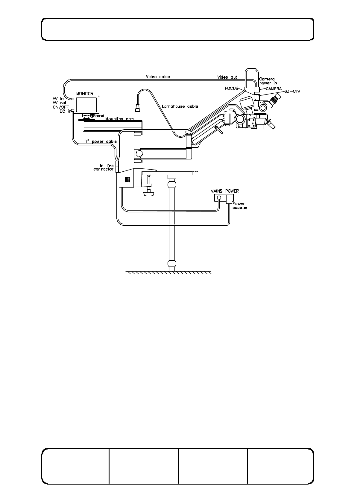
8. Attach the ‘Y’cable to the power adapter cable using the in-line connectors. Connect the
small right-angled power plug to the monitor DC in socket and the large straight power plug to
the camera DC in socket. Plug the power adapter in to a mains socket using a mains plug
adapter as necessary. Note that the power adapter will automatically detect mains voltages
between 100 and 240V, 50-60Hz. Refer to figure 15.
9. Connect the Monitor (AV in) to camera (video out) using the video cable. Switch the moitor
on. Refer to figure 15.
10. Note that the moitor may be connected to a video recorder to tape camera output. To
connect to a video recorder, use the AV out socket located below the AV in socket on the
monitor, and connect to the AV in of your video recorder.
11. Bring the right eyepiece of the microscope into focus.
12. Adjust the left eyepiece to focus.
13. If the picture on the monitor is unfocussed, adjust focus at rear of the SZ-CTV attachment
below the camera. Refer to figure 15.
14. If the picture is at an angle, loosen the retaining screw and rotate the camera assembly in its
mount until the picture is upright. Re-tighten the screw.
15. Adjust the picture using the brightness, contrast, and colour controls located on the side of the
monitor.
ISSUE NUMBER: 5.0
DATE: 11/04/02
SUPERSEDES: 4.0
DATE: 22/05/01
WRITTEN BY: RJK
DATE: 22/08/97
CHECKED BY: NW
DATE: 22/08/97
SO-5000 Ophthalmic Microscope User Manual Page 28 of 36
ISSUE NUMBER: 5.0
DATE: 11/04/02
Figure 15 Video System Sc hematic
SUPERSEDES: 4.0
DATE: 22/05/01
WRITTEN BY: RJK
DATE: 22/08/97
CHECKED BY: NW
DATE: 22/08/97

SO-5000 Ophthalmic Microscope User Manual Page 29 of 36
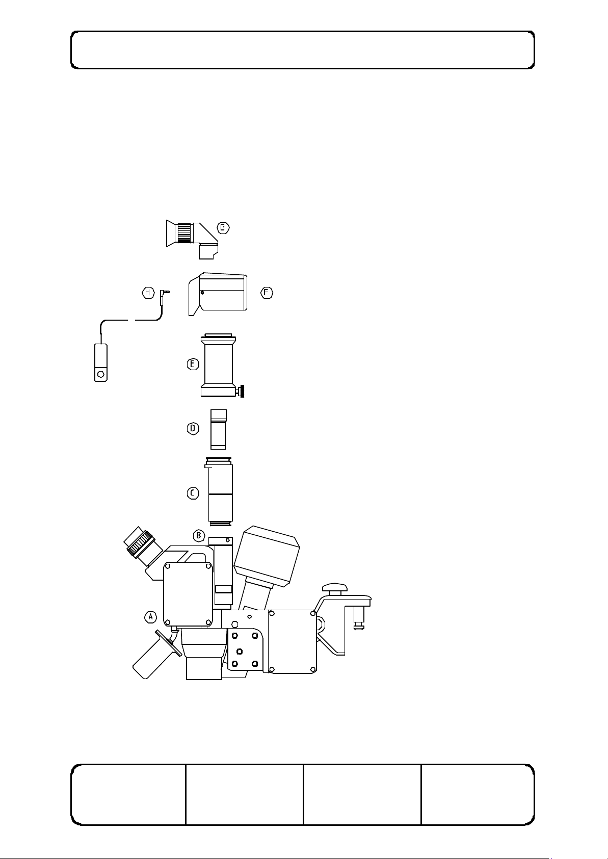
ATTACHING THE CAMERA ADAPTER
1. Remove the protective plastic cap on the trinocular attachment (B) by unscrewing the
fasteners located on either side.
2. Attach the photo tube (C) on the trinocular attachment as shown and secure by screwing the
fasteners back in.
3. Carefully insert the photo eyepiece (D) into the photo tube. Note that the photo eyepiece
must be removed from the photo tube if the assembly is to be transported.
4. Attach the photomicro adapter (E) to the photo tube and secure by tightening the knob on the
bottom of the adapter.
5. Attach the camera (F) on the top of the photomicro adapter.
6. Attach the Vari-Magnifinder and/or remote cord as required.
DISASSEMBLING THE CAMERA ADAPTER
1. To disassemble the photographic apparatus, simply perform the steps above in reverse. Note
that the photo eyepiece must be removed from the photo tube when the apparatus is
dismantled.
2. Take care to ensure that protective caps provided with the components (e.g. photo tube,
trinocular attachment) are replaced after use.
ISSUE NUMBER: 5.0
DATE: 11/04/02
SUPERSEDES: 4.0
DATE: 22/05/01
WRITTEN BY: RJK
DATE: 22/08/97
CHECKED BY: NW
DATE: 22/08/97
SO-5000 Ophthalmic Microscope User Manual Page 30 of 36
KEY TO FIGURE 16:
A: Scan Optics SO-111
Microscope head
and lamphouse
assembly
B: Olympus SZ-TRU
trinocular
attachment
C: Olympus SZ-PT
photo tube
D: Olympus NFK 2.5 x
LD photo eyepiece
E: Olympus
OM-mount
photomicro
adapter L
F: Olympus SC 35
Camera
G: Olympus MFVS
Vari-Magni finder
H: Olympus M Remote
cord
Figure 16 Assembl ing the 35mm camera attachments
ISSUE NUMBER: 5.0
DATE: 11/04/02
SUPERSEDES: 4.0
DATE: 22/05/01
WRITTEN BY: RJK
DATE: 22/08/97
CHECKED BY: NW
DATE: 22/08/97
 Loading...