

Scanner SDX7 User Manual

TThhe
e
S
S
c
c
a
a
n
n
n
n
e
e
r
r
VHF RADIO SYSTEM
SPECIFICATIONS
MODEL: SDX7
USER GUIDE
SDX7 Receiver
Receiver Mode: Crystal controlled single channel
Receiver Type: Non-diversity
Carrier Frequency: Spot frequency, factory set
Frequency Stability: 0.005%
Deviation: 15KHz (max)
Sensitivity: 20dBµ V (S/N ratio > 60 dB)
De-emphasis: 50µS
Image & Spurious Rejection: >70dB
S/N Ratio: > 60dB
T.H.D: < 0.5%
Frequency Response: 50Hz – 15KHz
Audio Output: Unbalanced 775mV, 5 KΩ load
Power Supply: DC 12-15V at 300mA
Dimension: 202 (L) x 134 (W) x 38 (H) mm
Weight: 290g
SDX7 Hand Held Microphone Transmitters
Operating Frequency: Spot frequency, factory set
Modulation: 15KHz (max)
RF Power Output: 2mW (max)
Pre-emphasis: 50µS
Spurious: > 60dB below carrier frequency (typical)
T.H.D: < 0.5%
Frequency Response: 50Hz – 15KHz Overall
Battery: MN1604
Battery Life: About 8 hours (with alkaline batteries)
Current Consumption: < 20mA
Dimension: 35mm diameter body, 238mm long. (Head 45mm diameter)
Weight: 188g (excluding battery)
www.jhs.co.uk
EXCLUSIVE WORLDWIDE TRADE DISTRIBUTORS:
JOHN HORNBY SKEWES & CO. LTD., SALEM HOUSE, PARKINSON APPROACH, GARFORTH, LEEDS LS25 2HR, UK.
Telephone: 01132 865381 Fax: 01132 868515 Email: info@jhs.co.uk
©2006 JHS & Co. Ltd. Specifications are subject to change without prior notice.
SDX7 Manual (A5 size) 23/10/06 16:17 Page 1
Thank you for purchasing THE SCANNER SDX7 DUAL CHANNEL VHF radio system. The following pages tell
you how to set up the system in order to get the best performance from it.
General considerations:
Always try to locate the receiver as close as possible to the transmitter, this minimizes the chance of there being
a
ny drop out.
Always try to ensure a line of sight signal path between the transmitter and receiver – obstacles such as walls
can significantly reduce the radio signal strength.
The receiver should never be sited close to computers or mobile telephone equipment, this could create unwanted
radio interference.
Always operate any radio microphone system with its antenna fully extended.
Always test a radio microphone system in the location where it is to be used by performing a `walk test'.
This means where the system is tested as the transmitter is 'walked' around the area in which it is to be used, with
the receiver remaining static. This will normally show up any problem areas, allowing you to try a new receiver
location. By adjusting the location of the receiver, or even just the alignment of its antenna, it should be possible
to obtain trouble free operation over the desired area, provided that it is not too large to exceed the transmitters
range, which is typically around 50m.
The SCANNER SDX7 MICROPHONE VHF outfit comprises:
VHF microphone transmitter x 2.
VHF receiver.
Audio lead.
Power supply.
Guarantee:
All SCANNER products are guaranteed for a period of one year from date of purchase against defects in materials
and workmanship. In the event of a claim under guarantee the system should be returned to your dealer in its original
packaging and with proof of purchase. Defects caused by modification, misuse or accident are not covered by the
guarantee.
Due to our continual policy of research and development we reserve the right to alter specifications without prior notice.
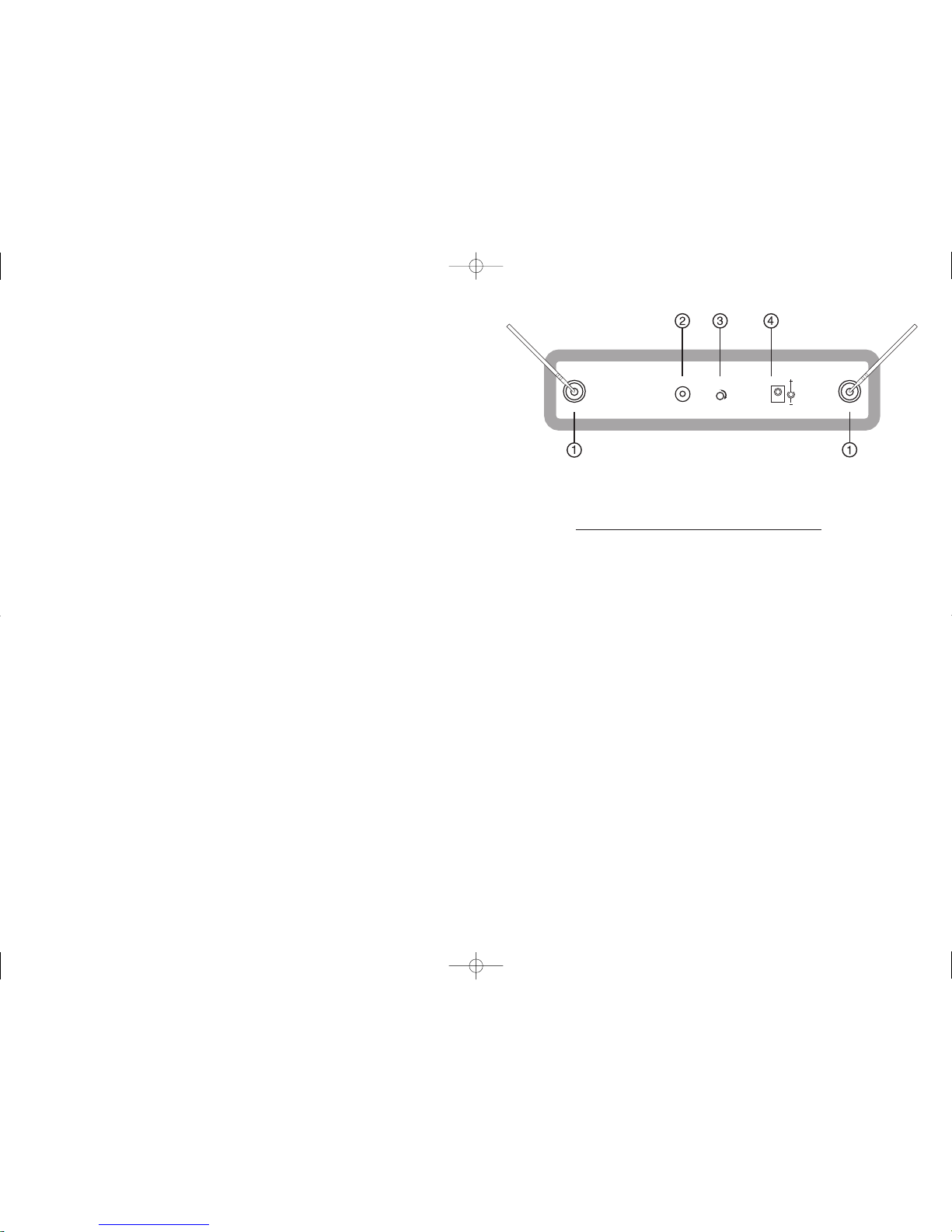
SDX7 receiver, setting up:
Fully extend the antennas, and set them to a "V" shape of around 90 degrees.
Connect the mains power adaptor to the DC input socket (Whatever number you allocate) on the rear panel, and
to the mains supply.
Only use the power supply provided with your SDX7 system.
Turn down the gain of your mixer or P Asystem and connect the audio output socket (Whatever number you allocate),
to the desired audio input on your system. The audio output of the SDX7 can be continuously varied with the
volume controls on the front panel, which should be adjusted for an adequate signal level to drive your sound system.
Note that you should always turn down the volume on your system whilst connecting in order to prevent a loud
`pop' as you connect the audio lead.
Setting the mute (SQ = Squelch) level:
The mute level is preset at the factory. If you need to adjust this, the easiest method is to have someone speaking
into the microphone whilst they walk away from you. When the background noise starts to become objectionable,
turn up the SQ control (Whatever number you allocate) until the receiver is silenced.
Microphone transmitter battery installation:
Each microphone requires a battery in order to function.
Unscrew the end of the microphone and fit a 1604 type 9V battery, taking care to observe the correct battery
polarity. If you fit the battery the wrong way round, no damage will occur, but the transmitter will not work.
Replace the end of the microphone.
Checking the transmitter battery:
Turn the transmitter power ON/OFF switch to the ON position and observe the RED LED just above it. A fresh
battery will cause the LED to flash once and then extinguish.
When the battery energy is almost expired, the LED will glow continuously – at this point, there is approximately
15 minutes of battery life remaining.
Never leave batteries in the transmitters whilst they are not in use. A discharged battery may leak acid into the
transmitter, destroying the circuitry.
SQ
D
C INPUT
12-15V
ANTENNA
AF OUT
ANTENNA
SDX7 Manual (A5 size) 23/10/06 16:17 Page 2
 Loading...