

Page 1
CANVIK TITAN
Operating Instructions
Bedienungsanleitung
Notice d’utilisation
Manual de instrucciones
Bedieningsinstructies
Instrukcja obsługi
Käyttöohjeet
GB
DE
F
ES
NL
PL
FI
1
Page 2
GB
INTRODUCTION
This manual shows the rules of safe operation, proper use, servicing and maintenance of the CANVIK
TITAN coil spring compressor station. The purpose of this manual is to ensure correct use, service and
a long service life of the spring compressor.
The manual shall be kept at a known location and be easily accessible for operators and maintenance
staff.
The employer (or owner of the spring compressor) is obligated to ensure that anyone using, servicing,
maintaining or repairing the spring compressor, have read this manual; as a minimum the parts that is
important for their job.
In addition; any person using, servicing, maintaining or repairing the spring compressor is obligated to
seek information in the manual.
MANUFACTURER
The CANVIK TITAN coil spring compressor is produced by
Company name: Scangrip A/S
Address: Rytterhaven 9, DK-5700 Svendborg, Denmark
PRODUCT NAME
The products full name is CANVIK TITAN spring compressor.
Item no. 10.0055.
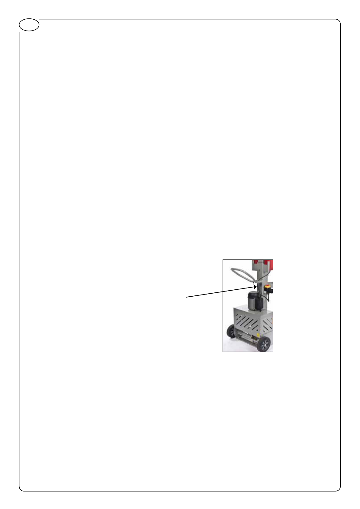
SERIAL NUMBER
The serial number is located underneath the handle.
2
Page 3

SAFETY INSTRUCTIONS
Working safely with this machine is possible only when the operating and safety information
are read completely and the instructions contained therein are strictly followed. Follow the
standard safety regulations for working with electrical equipment to reduce the risk of accidents. The manual shall be kept in a known location and be easily accessible for operators and
maintenance staff.
1. The machine may only be operated by persons who are authorised and have read and understood
this manual.
2. Before each use, check the unit for full functional capability. If the functional capability is not ensured or if damage is tdetected, the unit should not be used. Do not make any construction changes
to the unit.
3. In case of failure, the machine must be stopped before the problem is solved.
4. If the number of operations is above the maximum recommended operations suggested by the
authority, breaks or shifting tasks should be planned throughout the day.
5. There is no danger of being exposed to hazardous materials or substances when working with the
spring compressor.
GB
6. OPERATORS Should be trained in starting and stopping the machine as well as instruction in the
use of emergency stop, addressing issues, security requirements for the machine, including the use
of personal protective equipment, review of visual warnings - meaning and action.
7. MAINTENANCE PERSONEL Should be trained in the machine’s functions, the machines failure
modes and their rectication, and operation and maintenance of the machine.
8. Check the cord frequently to ensure that it has not been in contact with sharp edges or alike.
Protect the cord against oil, heat and sharp edges.
9. Use only suitable jaws for the springs. Ensure that the spring is positioned correctly in the jaw. The
centre line of the spring must be centered in both jaws. The centre line of the spring must always
be parallel to the compressing device, especially for conical springs and ball springs.
10. When compressing the spring, neither the spring windings nor the jaws should come in contact
with each other.
11. The bolts of the jaws must always be rmly tightened.
12. It is very important that the safety cage is always used when activating the compressor.
13. Always wear suitable protective eyewear and working gloves. Do not wear loose clothing that can
get caught in the machine.
14. Safety tip shoes should be worn when using or maintaining the spring compressor.
15. The noise level is measured above 70 dB so ear protection or ear plugs are recommended when
using the machine.
16. Vibrations caused by the spring compressor do not pose any danger for the user.
3
Page 4
GB
17. Keep the workplace clean and tidy at all times. Ensure that a re extinguisher is at hand.
18. Do not use the machine where there is danger of explosion or in wet or moist surroundings where
electric chock can occur.
19. Concentrate your attention on the work. Bear the potential risk of accidents in mind to ensure that
they do not happen. Use your common sense and do not work the machine if you are ill or tired or
under the inuence of alcohol or drugs
20. Do not use the machine for other purposes than it was designed for and do not overload the
machine.
21. Clean your tools carefully and store in safe place after each use – do not use compressed air for
cleaning, use only a soft brush.
22. Disconnect the power cord when the machine is not in use and store out of children’s reach.
23. Never leave the machine unattended.
24. Only use manufacturer recommended parts.
25. Only connect to an AC 230V single phase power supply with 10A/16A fuses and master switch.
4
Page 5
TECHNICAL SPECIFICATIONS
Item No. 10.0055
Max load 2500 kgs
Jaws: 1 set of universal jaws included
Spring capacity: ø80-200mm
Min distance between jaws: 65 mm
Max distance between jaws: 455m
Measurements: H1630x L794 x W670mm
Weight: 102 kgs
Operating voltage: 230V AC
Frequency: 50-60 Hz
Power consumption 1KW
GB
CONSUMABLES
Hydraulic oil: Mobil DTE 10 Excel Series
Grease: Super Lube® Aerosol
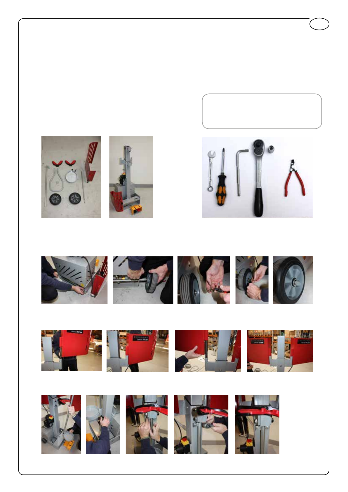
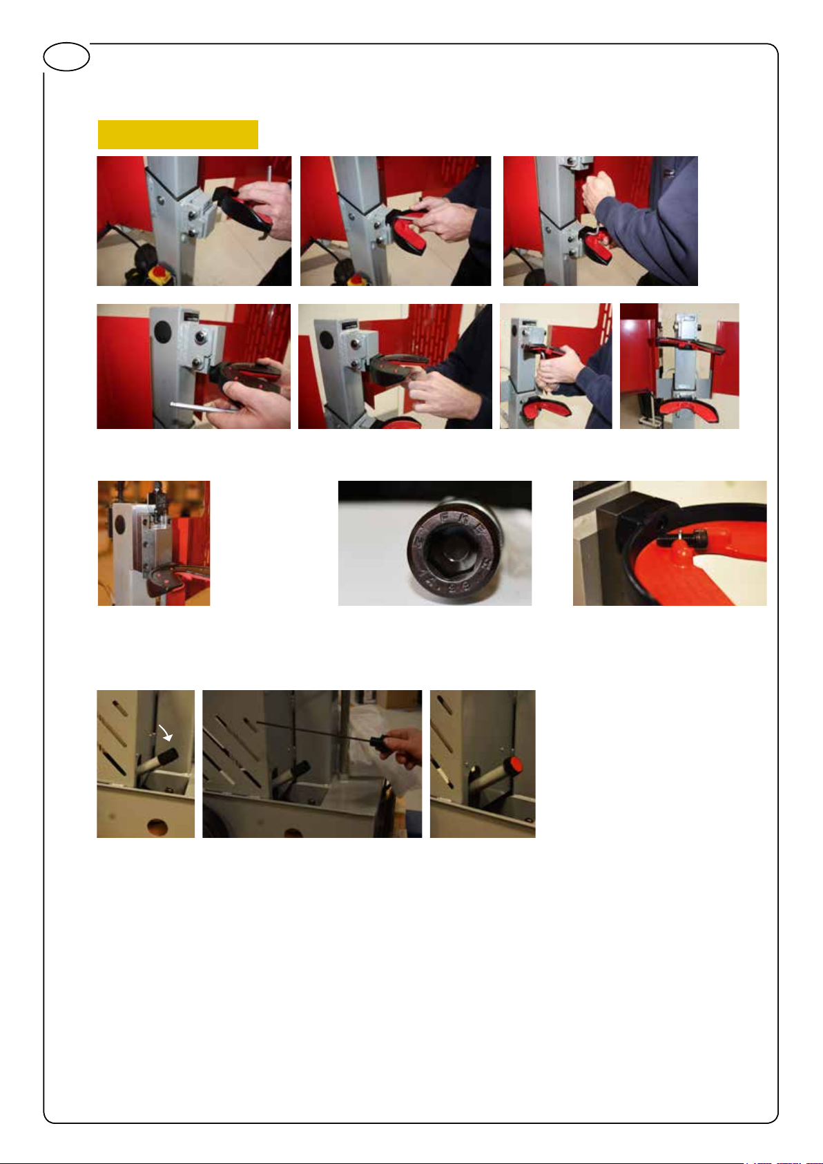
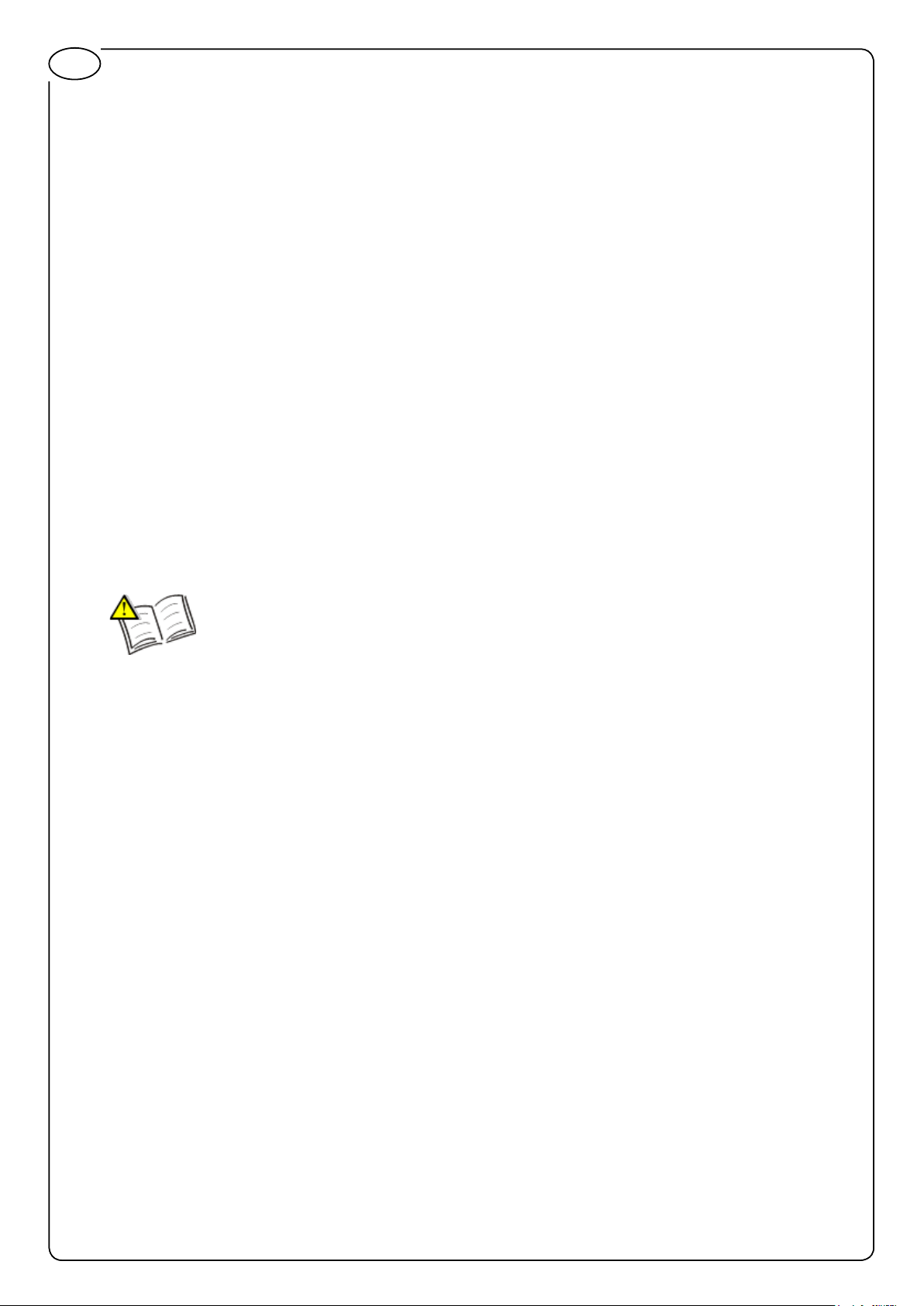
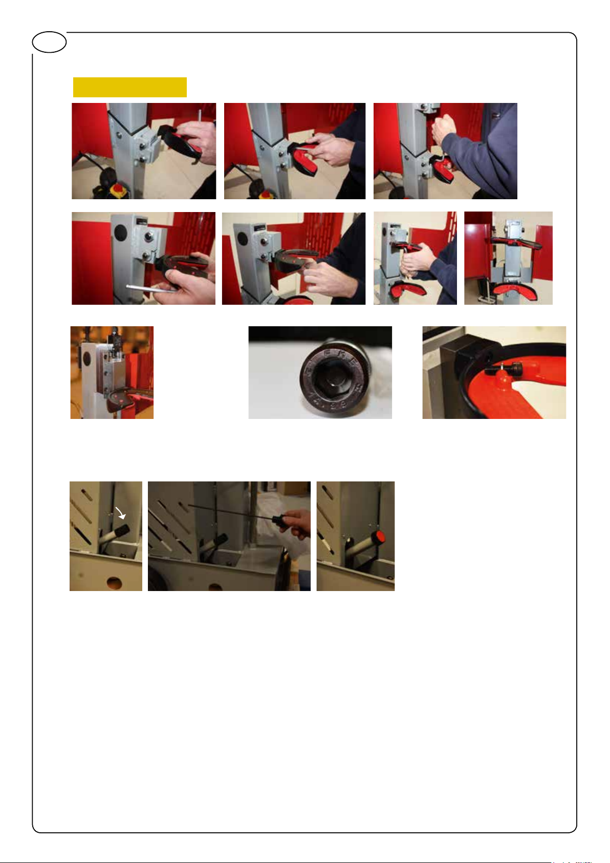
ASSEMBLING
Wheels
Safety cage
Catch bowl and sliding pale
Use circlip pliers
Fasten with 2xM8 bolts
5
Page 6
GB
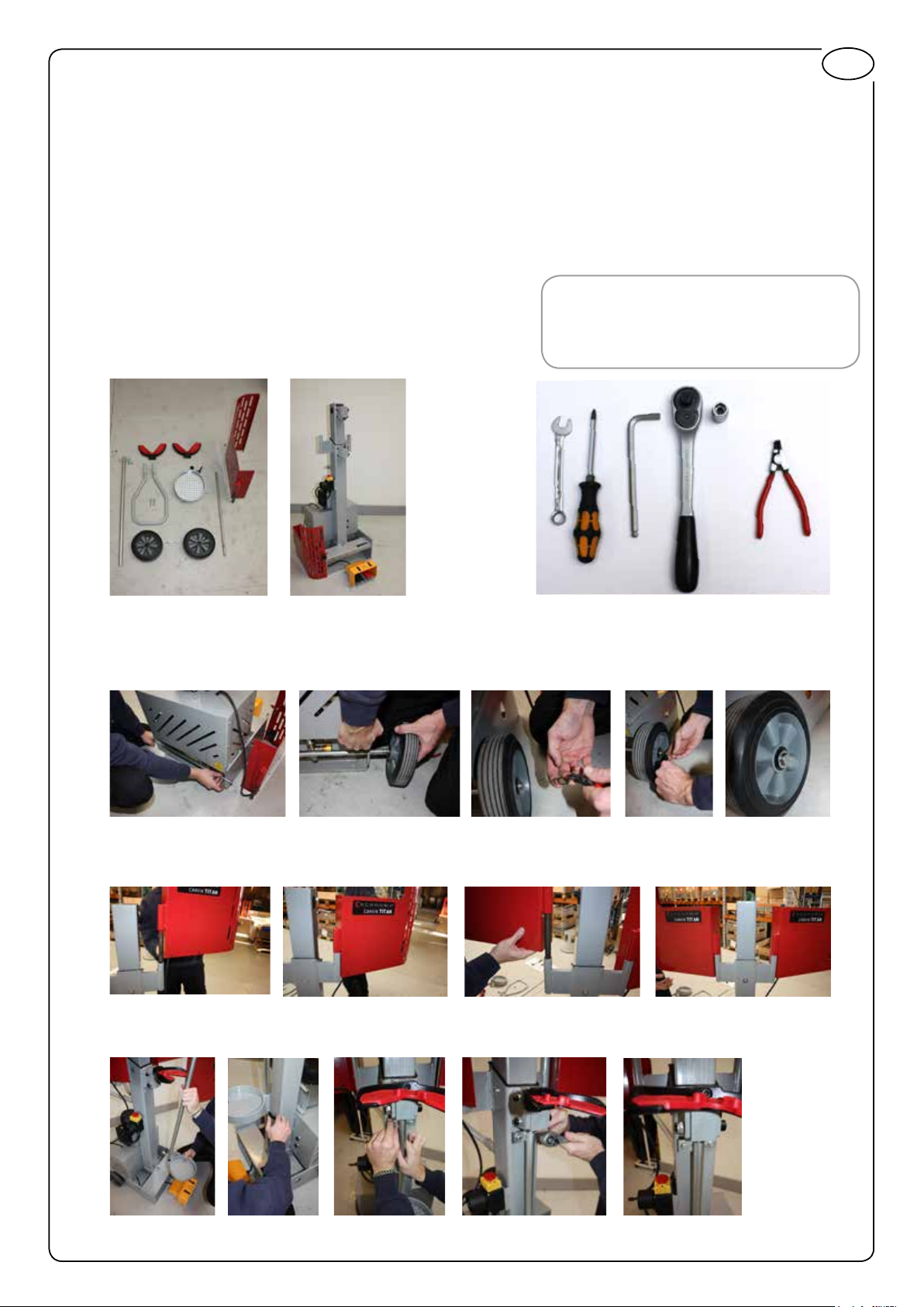
Jaws
VERY IMPORTANT!
Fasten very carefully with 8mm Allen key
Upper mounting block should
be lubricated (Super Lube
Before rst use
Remove transportation cover and replace with dipstick for oil level check
®
Aerosol)
Only use correct bolts (DIN 912. M10x30 grade 14.99)
with split lock washer (DIN 7980 M10)
INSTALLATION AND TRANSPORT
The location must be fully lit so installation and subsequent use can be carried out safely.
The site of operation must be cleared and there cannot be hazardous uids on the oor or dangerous
edges on adjacent machines or parts that can injure the operator if he/she falls or trips.
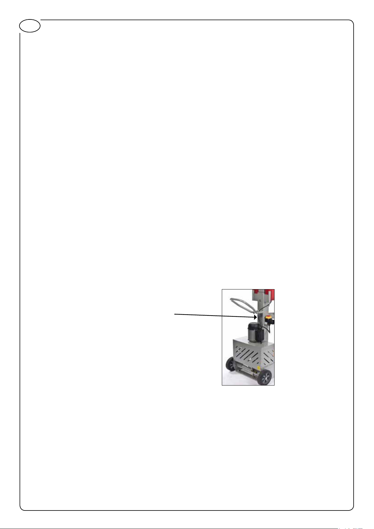
To move CANVIK TITAN, press down on the handle until the wheels support the spring compressor.
There is no need to xate the spring compressor.
6
Page 7

OPERATION
The coil spring compressor is exclusively for compressing and decompression of McPherson strut
springs whereby suitable jaws must be used. Any other or further use is considered not as intended.
Fit the jaws on the coil spring compressor using the supplied bolts.
Tighten the Allen bolts rmly. It is very important for your safety that the bolts of the jaws are rmly
tightened.
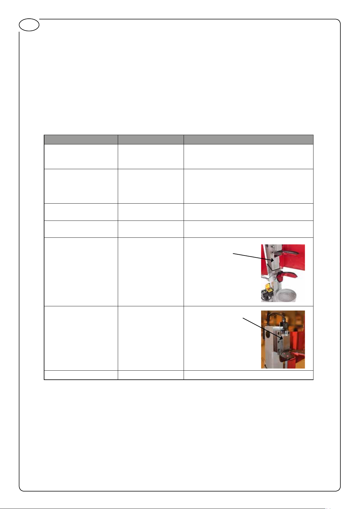
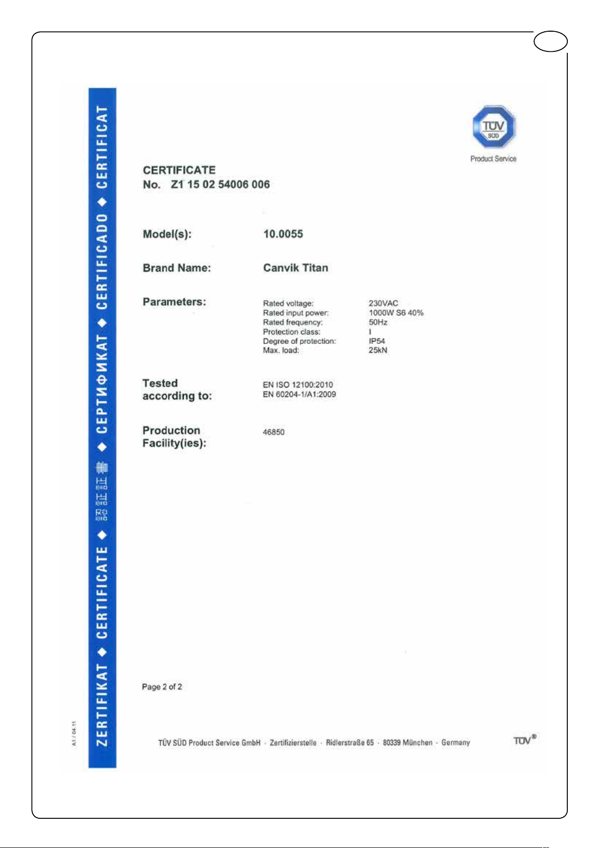
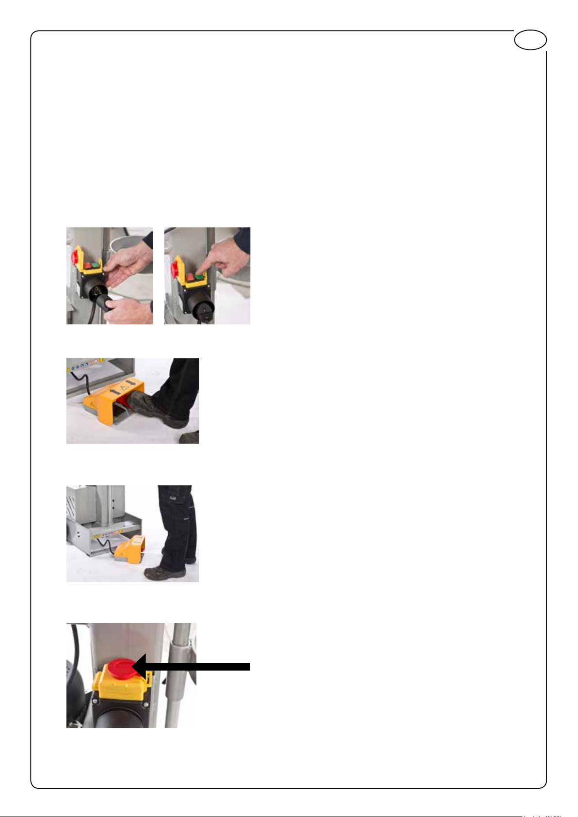
START OPERATION BY Connecting the motor to 230V. Make sure that the machine is connected to
earth. Activate the green button behind the emergency stop.
GB
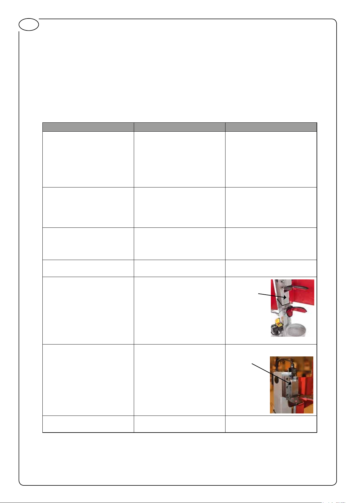
Press the right foot pedal to press the spring or the left to release the spring
STOP: Release the foot pedal
EMERGENCY STOP: Press the emergency stop at the left side of the spring compressor.
EMERGENCY STOP
Adjustments are made to the vent that regulates the automatic stop for fastening the spring.
7
Page 8

GB
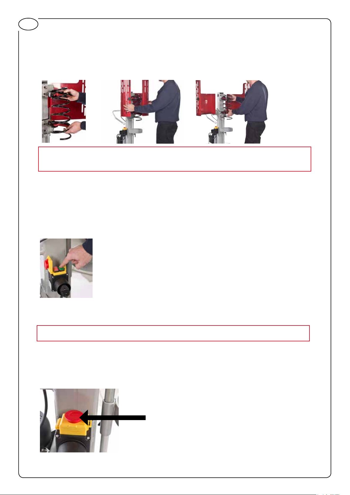
INSERTING THE SPRING
When inserting the spring the rst step is to move the spring holders apart until there are room for the
spring. Insert the spring. Use the right foot pedal to press the spring until it automatically stops. The
spring is now fastened and the safety cage can be closed before compressing the spring.
Deactivate the safety mechanism by closing the safety cage to compress the spring
REMOVING SPRING
To remove the spring the spring holders are moved apart until they almost loose grip of the spring,
then the safety cage is opened and the spring holders are moved apart until the spring can beremoved.
RETURNING TO OPERATION AFTER FAILURE OR EMERGENCY
The emergency stop is switched off and the greent button is activated.
BUILT-IN SAFETY PRECAUSIONS
Moving parts are shielded so that there are no risks related to the use of the machine.
The spring cannot be compressed unless the safety cage is closed.
It is not allowed to use the spring compressor without the safety cage.
Before use make sure that the safety cage is securely closed after mounting the spring.
There is an emergency switch on the left side of the spring compressor.
EMERGENCY STOP
8
Page 9
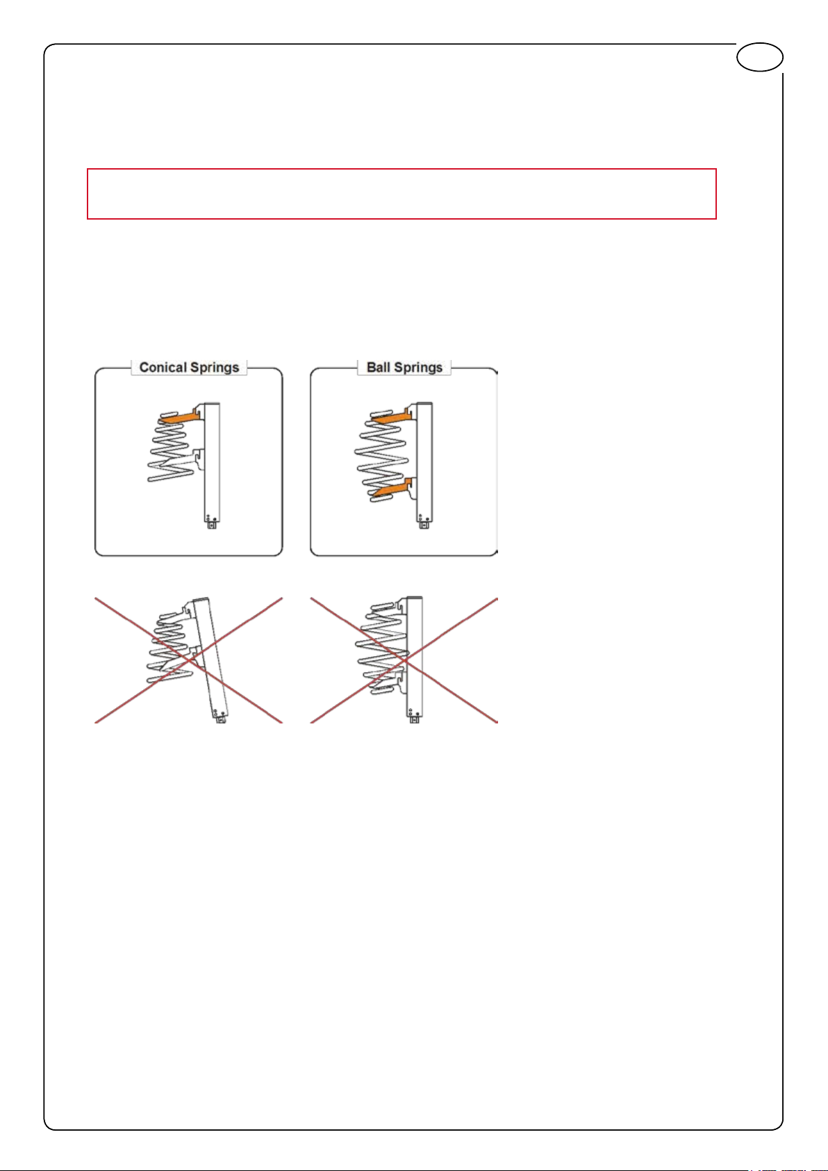
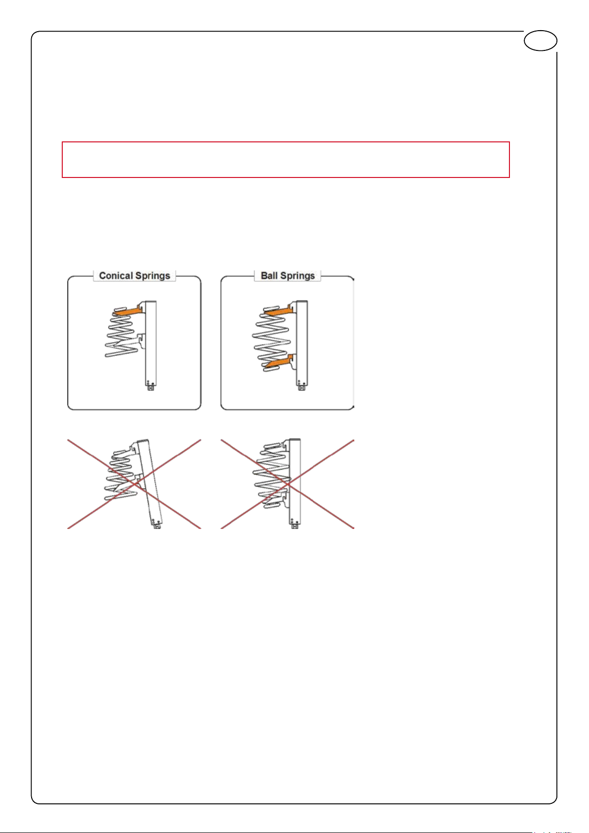
CONICAL SPRINGS:
Use the raised jaw 90.0060 to ensure that the centre line of the spring is parallel to the compressing
device. Do not use the coil spring compressor for conical springs if this is not the case. Fit the
raised jaw 90.0060 at the spring end with the smallest diameter.
It is very important for your safety that the jaws are tted correctly and that the
bolts are rmly tightened before use.
BALL SPRINGS:
Use the raised jaw 90.0060 to ensure that the centre line of the spring is parallel to the compressing
device. Do not use the coil spring compressor for ball springs if this is not the case. Fit raised jaws
90.0060 at both spring ends.
It is very important for your safety that the jaws are tted correctly and that the bolts are rmly
tightened before use.
GB
ACCESSORIES
Special purpose jaws for all kinds of springs:
Jaw “counterclock” for springs ø145-195mm 90.0025
Jaw tting spring diameters of Ø140-175 mm 90.0030
Jaw tting spring diameters of Ø180-230 mm 90.0040
Jaw tting spring diameters of Ø80-120 mm 90.0050
Jaw, Ø80-145 mm for conical and ball springs 90.0060
Jaw for BMW E39, E46, Renault Megane II and Toyota Avensis 90.0070
Jaw for Mercedes C-class 90.0080
Jaw for Mercedes E-class and Renault Megane II 90.0090
Jaws (pair) for Peugeot Break, Citroën C15 90.0100
Jaw for Chrysler Grand Voyager, “counter clock” spring 90.0120
SPARE PARTS
Standard jaw for ø80-200mm incl polyurethane insert 10.0010
Foot pedal 10.0055.01
Trolley wheel 10.0055.02
9
Page 10
GB
MAINTENANCE, TROUBLESHOOTING AND REPAIR
CLEANING AND ORDER
The workstation must be cleared of objects that could obstruct the free movement of the operator, as
moving springs in and out of the spring compressor. The oor around the workstation must be cleared
of objects or uids that could make the operator slip or fall.
SERVICE AND MAINTENANCE
Shut off the engine before service or maintenance.
After completing service or maintenance make sure that shields and safety measures are in place and
working.
Failure to follow this warning can cause serious injury.
What? When? How?
Tubes Monthly Check for visible wire mesh and leaks.
Replace any worn or damaged tubes before
starting the engine.
Hydraulic oil level
(Mobil DTE 10 Excel
Series)
Monthly Check that oil level is between the 2 strokes
on the dipstick. If necessary, add sufcient
amount of low freezing point hydraulic oil
Hydraulic ttings Monthly Check for cracks and leaks. Replace any
damaged ttings before starting the engine
Bolts fastening the jaws Every use Check for loose bolts
Column Monthly Lubricate the column with
lithium grease
Sliding block
(Super Lube
Moving parts Monthly Remove any dirt
®
Aerosol)
Monthly Lubricate the sliding block
with grease
GUARANTEE
This tool carries a guarantee according to current law. Subject to change without notice.
TERMINATION OF USE
The machine is separated and sorted and disposed of according to local regulations.
10
Page 11
Scangrip
5700 Svendborg, Denmark
Product Code:
10.0055
Low Voltage Directive (LVD), 2006/95/EC
Restriction of the use of certain Hazardous Substances in electrical and electronic equipment Directive (RoHS), 2011/65/EU
EN 50581:2012
GB
EC Declaration of Conformity
We, Scangrip A/S
Rytterhaven 9
Internal Ref. Nr.: ECdoc10.0055
2014
Declare under our responsibility for the product:
Product Range: NAME: Canvik Titan
DESCRIPTION: Hydraulic vertical coilspring compressor
The designated product is in conformity with the essential requirements of the following European
Directives and harmonized standards:
EN 60204-1:2006 Safety of machinery - Electrical equipment of machines - Part 1: General requirements
Electromagnetic compatibility Directive (EMC), 2004/108/EC
EN 55015:2006+A1:2007+A2:2009
The provisions of the machinery Directive (directive 2006/42/ET May 17th2006) and with national implementation legislation
EN ISO12100:2010 Safety of machinery - General principles for design - Risk assessment and risk reduction
REGULATION (EC) No 1907/2006 OF THE EUROPEAN PARLIAMENT AND OF THE COUNCIL of 18 December 2006
concerning the Registration, Evaluation, Authorisation and Restriction of Chemicals (REACH), establishing a European Chemicals Agency,
amending Directive 1999/45/EC and repealing Council Regulation (EEC) No 793/93 and Commission Regulation (EC) No 1488/94 as well as Council
Directive 76/769/EEC and Commission Directives 91/155/EEC, 93/67/EEC, 93/105/EC and 2000/21/EC.
28.08.2014 Anders Borring
General Manager
28.08.2014 Nikolaj Poffler
Keeper of technical Documents.
EC Declaration of Conformity, EC DoC
11
Page 12

12GB13GB14
Page 13
Page 14
DE
EINLEITUNG
Diese Anleitung zeigt die Prinzipien für sicheren Betrieb, richtigen Gebrauch, Service und Wartung
der CANVIK TITAN Federspannerstation. Diese Anleitung soll den richtigen Gebrauch und Service
sowie eine lange Nutzungsdauer des Federspanners sicherstellen.
Die Anleitung muss an einem allgemein bekannten Platz aufbewahrt werden und für das Bedienund Wartungspersonal einfach zugänglich sein.
Der Arbeitgeber (bzw. Eigentümer des Federspanners) ist verpichtet sicherzustellen, dass jede
Person, die den Federspanner benutzt, pegt, wartet oder repariert, zuvor diese Anleitung bzw.
mindestens die für die jeweilige Arbeit relevanten Teile gelesen hat.
Außerdem muss sich jede Person, die den Federspanner benutzt, pegt, wartet oder repariert, in
dieser Anleitung informieren.
HERSTELLER
Die CANVIK TITAN Federspannerstation wird hergestellt von
Unternehmensname: Scangrip A/S
Adresse: Rytterhaven 9
DK-5700 Svendborg, Dänemark
PRODUKTNAME
Der vollständige Produktname ist CANVIK TITAN Federspannerstation.
Artikel-Nr. 10.0055.
SERIENNUMMER
Die Seriennummer bendet sich unter dem Griff.
Page 15

SICHERHEITSHINWEISE
Die sichere Arbeit mit dieser Maschine ist nur möglich, wenn die Betriebs- und
Sicherheitsinformationen vollständig gelesen und die hierin enthaltenen Anleitungen strikt
befolgt werden.
Befolgen Sie die Sicherheitsvorschriften für die Arbeit mit elektrischen Ausrüstungen, um das
Unfallrisiko zu verringern.
1. Die Maschine darf nur von befugten Personen bedient werden, die diese Anleitung gelesen und
verstanden haben.
2. Die Maschine vor Gebrauch auf vollständige Funktionsfähigkeit prüfen. Wenn die Funktionsfähigkeit
nicht gewährleistet ist bzw. Schäden erkannt werden, darf die Maschine nicht benutzt werden. An
der Maschine keine Konstruktionsänderungen vornehmen.
3. Bei Fehlfunktionen muss die Maschine gestoppt werden, bevor der Fehler beseitigt wird.
4. Wenn die Zahl der Bedienvorgänge das von den Behörden empfohlene Maximum überschreitet,
müssen für den Arbeitstag Pausen bzw. Aufgabenwechsel eingeplant werden.
5. Bei der Arbeit mit dem Federspanner besteht keine Gefahr, gefährlichen Materialien oder
Substanzen ausgesetzt zu werden.
DE
6. Das BeDie nperso nal muss darin geschult werden, die Maschine ein- und auszuschalten, den
Notstopp zu betätigen und Probleme zu lösen, und muss mit den Sicherheitsanforderungen der
Maschine vertraut gemacht werden, einschließlich der Benutzung persönlicher Schutzausrüstung
und optischer Warnungen, deren Bedeutung und der notwendiger Maßnahmen.
7. WarTUnGspersonal muss zu den Maschinenfunktionen, den Fehlermodi und deren
Beseitigung, dem Betrieb und der Wartung der Maschine geschult werden.
8. Die Netzleitung regelmäßig darauf kontrollieren, dass sie keine scharfen Kanten o. ä. berührt. Die
Netzleitung vor Öl, Wärme und scharfen Kanten schützen.
9. Für die Federn nur geeignete Federhalter benutzen. Sicherstellen, dass die Feder richtig im
Federhalter sitzt. Die Mittellinie der Feder muss in beiden Federhaltern zentriert sein. Besonders
bei konischen Federn und Federkugeln muss die Mittellinie der Feder stets parallel zur
Spannvorrichtung verlaufen.
10. Beim Spannen der Feder dürfen sich die Federwindungen und die Federhalter nicht berühren.
11. Die Bolzen der Federhalter müssen stets fest angezogen werden.
12. Bei der Benutzung des Federspanners muss unbedingt immer der Sicherheitskäg benutzt werden.
13. Stets Schutzbrille und -handschuhe tragen. Keine lockere Kleidung tragen, die sich in der
Maschine verfangen kann.
14. Bei Benutzung bzw. Wartung des Federspanners stets Sicherheitsschuhe mit Schutzkappen tragen.
15. Der gemessene Geräuschpegel beträgt mehr als 70 dB. Bei Benutzung der Maschine sollten
deshalb ein Gehörschutz bzw. Ohrstöpsel getragen werden.
16. Vom Federspanner erzeugte Schwingungen stellen keine Gefahr für den Benutzer dar.
15
Page 16
DE
17. Den Arbeitsplatz jederzeit sauber und aufgeräumt halten. Die Verfügbarkeit eines Feuerlöschers
sicherstellen.
18. Die Maschine nicht bei Explosionsgefahr bzw. in nasser oder feuchter Umgebung benutzen, in der
elektrische Schläge möglich sind.
19. Die volle Aufmerksamkeit auf die Arbeit richten. Potenzielle Risiken bedenken, damit keine Unfälle
geschehen. Stets vernünftig handeln und die Maschine bei Müdigkeit, Alkohol- oder Drogeneinuss
nicht benutzen.
20. Die Maschine nicht für andere als die vorgesehenen Zwecke benutzen und nicht überlasten.
21. Das Werkzeug nach jeder Benutzung sorgfältig reinigen und an einem sicheren Platz lagern – für
die Reinigung keine Druckluft, sondern nur eine weiche Bürste benutzen.
22. Das Netzkabel bei Nichtgebrauch der Maschine trennen und außerhalb der Reichweite von Kindern
lagern.
23. Die Maschine nie unbeaufsichtigt lassen.
24. Nur vom Hersteller empfohlene Ersatzteile benutzen.
25. Die Maschine nur an einphasige 230-V-Wechselspannung mit 10 A/16 A Sicherungen und
Hauptschalter anschließen.
16
Page 17
TECHNISCHE SPEZIFIKATIONEN
Artikel-Nr. 10.0055
Max. Last 2500 kg
Federhalter: 1 Satz Universalfederhalter im Lieferumfang
Federdurchmesser: ø 80-200 mm
Mindestabstand zwischen Federhaltern: 65 mm
Maximalabstand zwischen Federhaltern: 455 mm
Maße: H 1630 x L 794 x B 670 mm
Gewicht: 102 kg
Betriebsspannung: 230 VAC
Frequenz: 50 - 60 Hz
Leistungsaufnahme 1 kW
BETRIEBSSTOFFE
Hydrauliköl: Mobil DTE 10 Excel Series
Schmierfett: Super Lube® Aerosol
DE
MONTAGE
Räder
Seegeringzange benutzen.
Sicherheitskäg
Transportdeckel entfernen und mit Ölmessstab ersetzen
Mit M8-Schrauben befestigen.
17
Page 18
DE
Leiste mit Ablage
SEHR WICHTIG!
Mit M8-Schrauben befestigen.
Oberen Montageblock mit
(Super Lube® Aerosol) einfetten
Vor dem ersten Gebrauch
Transportdeckel entfernen und mit Ölmessstab ersetzen
Nur die korrekten Schrauben (DIN 912. M10x30 Güteklasse
14.99) mit Federringen (DIN 7980 M10) benutzen
INSTALLATION UND TRANSPORT
Der Installationsplatz muss gut beleuchtet sein, um die Sicherheit bei Montage und späterem
Gebrauch zu gewährleisten. Der Arbeitsplatz muss gereinigt werden. Es dürfen sich keine gefährlichen
Flüssigkeiten auf dem Boden bzw. keine gefährlichen Kanten an benachbarten Maschinen benden bzw.
Teile vorhanden sein, die das Bedienpersonal bei Sturz/Stolpern verletzen können.
Zur Bewegung des CANVIK TITAN den Griff herunterdrücken, bis die Räder den Federspanner tragen.
Der Federspanner muss nicht xiert werden.
18
Page 19
BEDIENUNG
Der Federspanner ist ausschließlich zum Spannen/Entspannen von McPherson-Federbeinen
vorgesehen, wofür geeignete Federhalter benutzt werden müssen. Jegliche andere oder weitere
Benutzung gilt als nicht vorgesehene Verwendung.
Die Federhalter mit den mitgelieferten Bolzen am Federspanner montieren.
Die Innensechskantschrauben fest anziehen. Es ist sehr wichtig für die Sicherheit, dass die Bolzen
der Federhalter fest angezogen werden.
Zum STARTden Motor an 230 V anschließen. Die Erdung der Maschine sicherstellen. Die grüne
Taste hinter dem Notstopp betätigen
DE
Das rechte Pedal zum Spannen der Feder bzw. das linke Pedal zum Entspannen der Feder drücken.
STOPP: Das Pedal lösen.
NOTSTOPP: Die Notstopptaste links am Federspanner drücken.
NOTSTOPP
Einstellungen erfolgen am Hydraulikventil, das den automatischen Stopp für die Federbefestigung regelt.
19
Page 20
DE
FEDER EINSETZEN
Zum Einsetzen der Feder werden zuerst die Federhalter auseinander bewegt, bis genügend Platz für
die Feder vorhanden ist. Dann die Feder einsetzen. Das rechte Pedal drücken, um die Feder bis zum
automatischen Stopp zu spannen. Die Feder ist nun befestigt. Vor dem Spannen der Feder wird der
Sicherheitskäg geschlossen.
Den sicherheitskäg Schliessen, um den sicherheitsmechanismus zu deaktivieren
und die feder zu spannen
FEDER ENTNEHMEN
Zum Entnehmen der Feder die Federhalter auseinander bewegen, bis sie die Feder gerade noch
halten. Dann den Sicherheitskäg öffnen und die Federhalter so auseinander bewegen, dass die
Feder entnommen werden kann.
WIEDERINBETRIEBNAHME NACH FEHLER/NOTFALL
Notstopp deaktivieren und grüne Taste drücken.
EINGEBAUTE SICHERHEITSVORKEHRUNGEN
Bewegliche Teile sind abgeschirmt, um Risiken bei der Benutzung der Maschine auszuschalten.
Die Feder kann nur gespannt werden, wenn der Sicherheitskäg geschlossen ist.
Der Federspanner darf nicht ohne den Sicherheitskäg benutzt werden.
Nach dem Einsetzen der Feder und vor Benutzung sicherstellen, dass der Sicherheitskäg fest
verschlossen ist.
Links am Federspanner bendet sich die Notstopptaste.
NOTSTOPP
20
Page 21
KONISCHE FEDERN:
Den erhöhten Federhalter 90.0060 benutzen, um sicherzustellen, dass die Mittellinie der Feder
parallel zur Spannvorrichtung verläuft. Wenn dies nicht der Fall ist, die Federspannerstation nicht
für konische Federn benutzen. Den erhöhten Federhalter 90.0060 auf der Federseite mit dem
geringeren Durchmesser montieren.
Für Ihre Sicherheit ist es sehr wichtig, dass vor der Benutzung die Federhalter
korrekt montiert und die Bolzen fest angezogen werden.
FEDERKUGELN:
Den erhöhten Federhalter 90.0060 benutzen, um sicherzustellen, dass die Mittellinie der Feder
parallel zur Spannvorrichtung verläuft. Wenn dies nicht der Fall ist, die Federspannerstation nicht
für Federkugeln benutzen. Die erhöhten Federhalter 90.0060 auf beiden Federseiten montieren.
Für Ihre Sicherheit ist es sehr wichtig, dass vor der Benutzung die Federhalter korrekt montiert und
die Bolzen fest angezogen werden.
DE
ZUBEHÖR
Spezial-Federhalter für alle Federarten:
„Counterclock“-Federhalter für Federn ø 145-195 mm 90.0025
Federhalter für Federdurchmesser Ø 140-175 mm 90.0030
Federhalter für Federdurchmesser Ø 180-230 mm 90.0040
Federhalter für Federdurchmesser Ø 80-120 mm 90.0050
Federhalter Ø 80-145 mm für konische Federn und Federkugeln 90.0060
Federhalter für BMW E39, E46, Renault Megane II und Toyota Avensis 90.0070
Federhalter für Mercedes C-Klasse 90.0080
Federhalter für Mercedes E-Klasse und Renault Megane ll 90.0090
Federhalter (Paar) für Peugeot Break, Citroën C15 90.0100
Federhalter für Chrysler Grand Voyager, „Counterclock”-Feder 90.0120
ERSATZTEILE
Standard-Federhalter für ø 80-200 mm einschl. Polyurethaneinsatz 10.0010
Pedal 10.0055.01
Trolleyrad 10.0055.02
21
Page 22
DE
WARTUNG, FEHLERSUCHE UND REPARATUR
SAUBERKEIT UND ORDNUNG
Der Arbeitsplatz muss frei von Gegenständen gehalten werden, die die ungehinderte Bewegung des
Bedienpersonals beim Einsetzen von Federn in die Federspannstation bzw. beim Herausnehmen
beeinträchtigen könnten. Der Boden im Bereich des Arbeitsplatzes muss frei von Gegenständen oder
Flüssigkeiten gehalten werden, die zum Ausrutschen bzw. Sturz des Bedienpersonals führen könnten.
SERVICE UND WARTUNG
Die Maschine vor Service und Wartung ausschalten.
Nach dem Abschluss von Service bzw. Wartung sicherstellen, dass die Abschirmungen und
Sicherheitsvorkehrungen montiert sind und funktionieren.
Die Nichtbeachtung dieses Warnhinweises kann schwere Verletzungen verursachen.
Was? Wann? Wie?
Rohre Monatlich Auf sichtbare Schäden
am Drahtgeecht und
Undichtigkeiten prüfen.
Alle verschlissenen bzw.
beschädigten Rohre vor
Inbetriebnahme der Maschine
austauschen.
Hydraulikölstand
(Mobil DTE 10 Excel Series)
Hydraulikttings Monatlich Auf Risse und Undichtigkeiten
Befestigungsbolzen der
Federhalter
Säule Monatlich Säule mit
Monatlich Prüfen, ob der Ölstand zwischen
den beiden Markierungen am
Peilstab liegt. Ggf. ausreichend
Hydrauliköl mit niedrigem
Gefrierpunkt nachfüllen.
prüfen. Alle beschädigten
Fittings vor der Inbetriebnahme
der Maschine austauschen.
Vor jeder Benutzung Auf lose Bolzen prüfen.
Lithiumfett
schmieren
Gleitblock
(Super Lube
Bewegliche Teile Monatlich Alle Verschmutzungen
GARANTIE
Für dieses Werkzeug gilt die gesetzliche Garantie. Änderungen ohne Vorankündigung vorbehalten.
®
Aerosol)
Monatlich Gleitblock mit Schmierfett
einfetten
entfernen.
AUSSERBETRIEBNAHME
Die Demontage, Abfalltrennung und Entsorgung der Maschine erfolgt gemäß den örtlichen
Vorschriften.
22
Page 23

Scangrip
DESCRIPTION: Hydraulic vertical coilspring compressor
Low Voltage Directive (LVD), 2006/95/EC
Directive 76/769/EEC and Commission Directives 91/155/EEC, 93/67/EEC, 93/105/EC and 2000/21/EC.
EN 50581:2012
DE
EC Declaration of Conformity
We, Scangrip A/S
Rytterhaven 9
5700 Svendborg, Denmark
Internal Ref. Nr.: ECdoc10.0055
2014
Declare under our responsibility for the product:
Product Range: NAME: Canvik Titan
Product Code: 10.0055
The designated product is in conformity with the essential requirements of the following European
Directives and harmonized standards:
EN 60204-1:2006 Safety of machinery - Electrical equipment of machines - Part 1: General requirements
Electromagnetic compatibility Directive (EMC), 2004/108/EC
EN 55015:2006+A1:2007+A2:2009
The provisions of the machinery Directive (directive 2006/42/ET May 17th2006) and with national implementation legislation
EN ISO12100:2010 Safety of machinery - General principles for design - Risk assessment and risk reduction
REGULATION (EC) No 1907/2006 OF THE EUROPEAN PARLIAMENT AND OF THE COUNCIL of 18 December 2006
concerning the Registration, Evaluation, Authorisation and Restriction of Chemicals (REACH), establishing a European Chemicals Agency,
amending Directive 1999/45/EC and repealing Council Regulation (EEC) No 793/93 and Commission Regulation (EC) No 1488/94 as well as Council
Restriction of the use of certain Hazardous Substances in electrical and electronic equipment Directive (RoHS), 2011/65/EU
28.08.2014 Anders Borring
General Manager
28.08.2014 Nikolaj Poffler
Keeper of technical Documents.
EC Declaration of Conformity, EC DoC
23
Page 24
24DE25DE26
Page 25

Page 26
F
INTRODUCTION
Le présent manuel établit les règles à suivre pour utiliser, exploiter, entretenir et réparer en toute
sécurité la station de compresseur à ressorts CANVIK TITAN. Son objectif est de permettre une
utilisation et une maintenance correctes du compresseur, ainsi que de garantir une longue vie utile.
Ce manuel doit être conservé à un emplacement connu et facilement accessible par l’ensemble des
opérateurs et du personnel de maintenance.
L’employeur (ou propriétaire du compresseur à ressorts) est tenu de s’assurer que toute personne
chargée d’utiliser, de réparer, d’entretenir ou de réviser le compresseur à ressorts a pris connaissance
du présent manuel, ou tout au moins des sections se rapportant à son travail.
En outre, toute personne chargée de l’utilisation, de la révision, de la maintenance ou de la réparation
du compresseur à ressorts doit impérativement rechercher les informations nécessaires dans ce
manuel.
FABRICANT
Le compresseur à ressorts CANVIK TITAN est fabriqué par :
Nom de la société : Scangrip A/S
Adresse : Rytterhaven 9
DK-5700 Svendborg, Danemark
NOM DU PRODUIT
Le nom complet de ce produit est « compresseur à ressorts CANVIK TITAN ».
Son n° de référence est le 10.0055.
NUMÉRO DE SÉRIE
Le numéro de série est situé sous la poignée.
Page 27

CONSIGNES DE SÉCURITÉ
Pour travailler en toute sécurité sur cette machine, il est impératif de lire entièrement et de
respecter strictement les consignes de sécurité et d’utilisation contenues dans le présent
manuel.
De même, observez les réglementations en matière de sécurité relatives aux équipements
électriques, an de réduire les risques d’accident.
1. Cette machine peut être utilisée uniquement par des opérateurs autorisés, ayant lu et compris le
présent manuel.
2. Avant chaque utilisation, vériez que l’unité est parfaitement fonctionnelle. Si la machine ne
fonctionne pas correctement ou si elle est endommagée, ne l’utilisez pas. N’apportez aucune
modication structurelle à l’unité.
3. En cas de panne, arrêtez la machine jusqu’à ce que le problème soit résolu.
4. Si le nombre d’opérations prévu est supérieur au nombre maximum recommandé par les autorités,
les tâches doivent être découpées ou alternées par équipe sur l’ensemble de la journée de travail.
5. Le compresseur à ressorts ne présente aucun danger en termes d’exposition à des substances ou
des matières dangereuses.
F
6. LES OPERATEURS Doivent être formés à la mise en marche et à l’arrêt de la machine, ainsi
qu’à l’utilisation du système d’arrêt d’urgence. Ils doivent également être capables de gérer les
problèmes qui peuvent survenir, de respecter les exigences en matière de sécurité, notamment
l’utilisation d’un équipement de protection individuelle, et de reconnaître les alertes visuelles
(signication et action requise).
7. LE PERSONNEL DE MAINTENANCE Doit être formé au fonctionnement et à la maintenance de
la machine et connaître les fonctions de la machine ainsi que les modes de défaillance et leurs
mesures correctives.
8. Vériez fréquemment le cordon d’alimentation an de vous assurer qu’il n’est pas en contact avec
des objets ou des rebords coupants. Protégez le cordon contre les risques que représentent des
éléments tels que l’huile, la chaleur et les objets coupants.
9. Utilisez uniquement des mâchoires adaptées aux ressorts. Assurez-vous que le ressort est
correctement positionné dans la mâchoire. La ligne médiane du ressort doit être centrée sur
les deux mâchoires. Elle doit en outre toujours être parallèle à l’unité de compression, tout
particulièrement dans le cas de ressorts coniques ou sphériques.
10. Lors de la compression du ressort, les enroulements du ressort et les mâchoires ne doivent pas
être en contact.
11. Les boulons des mâchoires doivent toujours être solidement serrés.
12. Il est très important de toujours utiliser la cage de sécurité lorsque le compresseur est activé.
13. Portez toujours des gants et des lunettes de protection adaptés. Évitez les vêtements amples qui
risqueraient de se coincer dans la machine.
14. Portez des chaussures de sécurité lors de l’utilisation ou de la maintenance du compresseur à
ressorts.
15. Le niveau sonore mesuré étant supérieur à 70 dB, une protection auditive ou des bouchons
d’oreille sont recommandés lors de l’utilisation de la machine.
27
Page 28

F
16. Les vibrations causées par le compresseur à ressorts ne constituent pas un danger pour
l’utilisateur.
17. Veillez à ce que la zone de travail soit toujours propre et rangée. Assurez-vous d’avoir toujours un
extincteur à proximité.
18. N’utilisez pas la machine en cas de risque d’explosion ou lorsque la zone de travail est mouillée ou
humide, pour éviter les chocs électriques.
19. Soyez concentré sur votre tâche lorsque vous utilisez la machine. Ayez toujours à l’esprit le risque
d’accidents pour éviter qu’il s’en produise. Faites preuve de bon sens et ne travaillez pas sur la
machine si vous êtes malade, fatigué ou sous l’inuence d’alcool, de médicaments ou d’autres
substances.
20. N’utilisez pas la machine à des ns autres que celles pour lesquelles elle a été conçue et évitez
toute surcharge.
21. Nettoyez soigneusement vos outils et rangez-les dans un endroit approprié après usage. N’utilisez
pas d’air comprimé pour le nettoyage ; préférez une brosse souple.
22. Débranchez le cordon d’alimentation lorsque la machine n’est pas utilisée et placez-le hors de
portée des enfants.
23. Ne laissez jamais la machine sans surveillance.
24. Utilisez uniquement des pièces détachées recommandées par le fabricant.
25. L’alimentation électrique se fait uniquement via une prise 230 V CA monophasé, avec fusibles 10
A/16 A et disjoncteur principal.
28
Page 29

SPÉCIFICATIONS TECHNIQUES
N° de référence : 10.0055
Charge maximale : 2 500 kg
Mâchoires : 1 jeu de mâchoires universelles inclus
Capacité de ressort : ø 80 à 200 mm
Distance minimale entre les mâchoires : 65 mm
Distance maximale entre les mâchoires : 455 mm
Dimensions : H 1 630 x L 794 x l 670 mm
Poids : 102 kg
Tension d’alimentation : 230 V CA
Fréquence : 50-60 Hz
Consommation électrique : 1 kW
CONSOMMABLES
Huile hydraulique: Mobil DTE 10 Excel Series
Graisse: Super Lube® Aerosol
F
MONTAGE
Roues
Cage de sécurité
Coupelle de blocage et poteau coulissant
Utiliser des pinces à circlip
Serrer avec des boulons M8
29
Page 30

F
Mâchoires
TRÈS IMPORTANT !
Serrer soigneusement avec une clé Allen de 8 mm
Lubrier le bloc de montage
supérieur (Super Lube® Aerosol)
Avant la première utilisation
Retirer la protection de transport et remplacer par la jauge de niveau d’huile
N’utiliser que des boulons adéquats (DIN 912. M10x30
qualité 14.99) avec rondelle d’arrêt fendue (DIN 7980 M10)
INSTALLATION ET TRANSPORT
Le site d’installation doit être correctement éclairé de manière à ce que l’installation de la machine et son
utilisation se fassent dans les meilleures conditions de sécurité possibles. La zone d’installation doit être
dégagée et exempte de tout liquide dangereux au niveau du sol. Aucune machine ou pièce à proximité
ne doit présenter des rebords ou autre risquant de blesser l’opérateur s’il venait à tomber.
Pour déplacer le CANVIK TITAN, appuyez sur la poignée jusqu’à ce que les roues supportent le poids
du compresseur à ressorts.
Il n’est pas nécessaire d’arrimer le compresseur.
30
Page 31

FONCTIONNEMENT
Le compresseur à ressorts doit servir exclusivement à la compression et à la décompression de
ressorts d’amortisseur McPherson, avec l’utilisation de mâchoires adaptées. Toute utilisation autre
que celle-ci sera considérée comme incorrecte.
Installez les mâchoires dans le compresseur à ressorts à l’aide des boulons fournis.
Serrez solidement les boulons avec une clé Allen. Pour votre sécurité, il est très important que les
boulons des mâchoires soient parfaitement serrés.
DÉMARRAGE : COMMENCEZ PAR Raccorder le moteur à une prise 230 V. Assurez-vous que la
machine est mise à la terre. Appuyez sur le bouton vert situé derrière l’arrêt d’urgence.
F
Appuyez sur la pédale de droite pour compresser le ressort ou sur la pédale de gauche pour le relâcher
ARRÊT : Relâchez la pédale.
ARRÊT D’URGENCE :
gauche du compresseur à ressorts.
Appuyez sur le bouton d’arrêt d’urgence situé sur le côté
ARRÊT D’URGENCE
Des réglages sont effectués au niveau de la ventilation qui régule l’arrêt automatique, pour attacher le ressort.
31
Page 32

F
MISE EN PLACE DU RESSORT
Lorsque vous mettez le ressort en place, la première étape consiste à écarter les supports an que
le ressort puisse passer. Installez le ressort. Servez-vous de la pédale de droite pour appuyer sur
le ressort, jusqu’à l’arrêt automatique. Le ressort est désormais xé et la cage de sécurité peut être
refermée avant de commencer la compression du ressort.
Désactivez le mécanisme de sécurité en fermant la cage de sécurité, pour
comprimer le ressort.
RETRAIT DU RESSORT
Pour sortir le ressort, écartez les supports jusqu’à ce qu’ils ne retiennent presque plus le ressort, puis
ouvrez la cage de sécurité. Les supports s’écartent pour permettre de retirer le ressort.
REMISE EN SERVICE APRÈS UNE PANNE OU UN ARRÊT D’URGENCE
Désactivez l’arrêt d’urgence et appuyez sur le bouton vert.
DISPOSITIFS DE SÉCURITÉ INTÉGRÉS
Les pièces mobiles sont protégées, de manière à éviter tout risque pour l’utilisateur.
La compression du ressort ne peut commencer tant que la cage de sécurité n’est
pas fermée.
Il est interdit d’utiliser le compresseur à ressorts sans cage de sécurité.
Avant utilisation, assurez-vous que la cage de sécurité est correctement fermée, après avoir mis le
ressort en place.
Un bouton d’arrêt d’urgence est situé sur le côté gauche du compresseur à ressorts.
ARRÊT D’URGENCE
32
Page 33

RESSORTS CONIQUES :
Utilisez la mâchoire surélevée réf. 90.0060 pour garantir que la ligne médiane du ressort est
parallèle à l’unité de compression. Si ce n’est pas le cas, n’utilisez pas le compresseur pour les
ressorts coniques. Installez la mâchoire surélevée réf. 90.0060 à la plus petite extrémité du ressort.
Pour votre sécurité, il est très important que les mâchoires soient correctement
installées et que les boulons soient solidement serrés.
RESSORTS SPHÉRIQUES :
Utilisez la mâchoire surélevée réf. 90.0060 pour garantir que la ligne médiane du ressort est
parallèle à l’unité de compression. Si ce n’est pas le cas, n’utilisez pas le compresseur pour les
ressorts sphériques. Installez une mâchoire surélevée réf. 90.0060 à chaque extrémité du ressort.
Pour votre sécurité, il est très important que les mâchoires soient correctement installées et que les
boulons soient solidement serrés.
F
ACCESSOIRES
Mâchoires spéciales pour tous types de ressort :
Mâchoire « sens gauche » pour ressorts ø 145-195 mm Réf. 90.0025
Mâchoire pour ressorts Ø 140-175 mm Réf. 90.0030
Mâchoire pour ressorts Ø 180-230 mm Réf. 90.0040
Mâchoire pour ressorts Ø 80-120 mm Réf. 90.0050
Mâchoire pour ressorts coniques et sphériques Ø 80-145 mm Réf. 90.0060
Mâchoire pour BMW E39, E46, Renault Megane II et Toyota Avensis Réf. 90.0070
Mâchoire pour Mercedes Classe C / Réf. 90.0080
Mâchoire pour Mercedes Classe E et Renault Megane ll Réf. 90.0090
Paire de mâchoires pour break Peugeot, Citroën C15 Réf. 90.0100
Mâchoire pour ressort « sens gauche » Chrysler Grand Voyager Réf. 90.0120
PIÈCES DÉTACHÉES
Mâchoire standard pour ressorts ø80-200 mm, avec insert polyuréthane Réf. 10.0010
Pédale Réf. 10.0055.01
Roue de chariot Réf. 10.0055.02
33
Page 34

F
MAINTENANCE, DÉPANNAGE ET RÉPARATION
NETTOYAGE ET ORGANISATION
La zone de travail ne doit contenir aucun objet pouvant entraver la liberté de mouvement de
l’opérateur, lors de la mise en place et du retrait des ressorts au niveau du compresseur. Le sol autour
de la machine doit être exempt d’objets et de liquide risquant de faire glisser ou tomber l’opérateur.
RÉVISION ET MAINTENANCE
Coupez le moteur avant toute opération de révision ou de maintenance.
Une fois l’opération de révision ou de maintenance terminée, assurez-vous que les protections et les
dispositifs de sécurité sont en place et fonctionnels.
Le non-respect de cette consigne peut entraîner des blessures graves pour l’opérateur.
Quoi ? Quand ? Comment ?
Tubes Chaque mois Vériez l’absence de fuites
et de zones endommagées.
Remplacez les tubes usés ou
endommagés avant de démarrer
le moteur.
Niveau d’huile hydraulique
(Mobil DTE 10 Excel Series)
Raccords hydrauliques Chaque mois Vériez l’absence de fuites et
Boulons de xation des
mâchoires
Colonne Chaque mois Lubriez la colonne avec de la
Chaque mois Vériez que le niveau d’huile se
situe entre les deux encoches
de la jauge. Si nécessaire,
ajoutez la quantité requise
d’huile hydraulique à point de
congélation bas.
de ssures. Remplacez tout
raccord endommagé avant de
démarrer le moteur.
À chaque utilisation Vériez que les boulons ne sont
pas desserrés.
graisse au
lithium.
Bloc coulissant
(Super Lube
Pièces mobiles Chaque mois Retirez les éventuelles saleté et
®
Aerosol)
Chaque mois Graisser le bloc coulissant
poussière.
GARANTIE
Cette machine dispose d’une garantie, conformément à la loi en vigueur. Celle-ci est sujette à
modication sans avis préalable.
CESSATION D’UTILISATION
Le démembrement de cette machine, le tri des pièces et la mise au rebut sont à effectuer
conformément aux réglementations locales.
34
Page 35

Scangrip
Electromagnetic compatibility Directive (EMC), 2004/108/EC
The provisions of the machinery Directive (directive 2006/42/ET May 17th2006) and with national implementation legislation
REGULATION (EC) No 1907/2006 OF THE EUROPEAN PARLIAMENT AND OF THE COUNCIL of 18 December 2006
F
EC Declaration of Conformity
We, Scangrip A/S
Rytterhaven 9
5700 Svendborg, Denmark
Internal Ref. Nr.: ECdoc10.0055
2014
Declare under our responsibility for the product:
Product Range: NAME: Canvik Titan
Product Code: 10.0055
DESCRIPTION: Hydraulic vertical coilspring compressor
The designated product is in conformity with the essential requirements of the following European
Directives and harmonized standards:
Low Voltage Directive (LVD), 2006/95/EC
EN 60204-1:2006 Safety of machinery - Electrical equipment of machines - Part 1: General requirements
EN 55015:2006+A1:2007+A2:2009
EN ISO12100:2010 Safety of machinery - General principles for design - Risk assessment and risk reduction
concerning the Registration, Evaluation, Authorisation and Restriction of Chemicals (REACH), establishing a European Chemicals Agency,
amending Directive 1999/45/EC and repealing Council Regulation (EEC) No 793/93 and Commission Regulation (EC) No 1488/94 as well as Council
Directive 76/769/EEC and Commission Directives 91/155/EEC, 93/67/EEC, 93/105/EC and 2000/21/EC.
Restriction of the use of certain Hazardous Substances in electrical and electronic equipment Directive (RoHS), 2011/65/EU
EN 50581:2012
28.08.2014 Anders Borring
General Manager
28.08.2014 Nikolaj Poffler
Keeper of technical Documents.
EC Declaration of Conformity, EC DoC
35
Page 36

36F37F38
Page 37

Page 38

ES
INTRODUCCIÓN
En este manual se indican las normas a seguir para un funcionamiento seguro, el uso apropiado,
la revisión y el mantenimiento del compresor para muelle helicoidal CANVIK TITAN. Su propósito
es garantizar un uso y un mantenimiento correctos, así como proporcionar una larga vida útil al
compresor para muelles.
Este manual se conservará en un lugar de fácil acceso para los operadores y el personal de
mantenimiento.
El empleador (o el propietario del compresor) tiene la obligación de asegurar que cualquier
persona encargada de utilizar, revisar, mantener o reparar el compresor, lea este manual, al
menos, las partes que son importantes para su trabajo.
Además, cualquier persona encargada de utilizar, revisar, mantener o reparar el compresor tiene la
obligación de consultar el manual.
FABRICANTE
El fabricante del compresor para muelle helicoidal CANVIK TITAN es:
Nombre de la compañía: Scangrip A/S
Dirección: Rytterhaven 9
DK-5700 Svendborg, Dinamarca
NOMBRE DEL PRODUCTO
El nombre completo del producto es compresor para muelles CANVIK TITAN. Artículo nº 10.0055.
NUMERO DE SERIE
El número de serie está situado debajo de la empuñadura.
Page 39

INSTRUCCIONES DE SEGURIDAD
Para poder trabajar con total seguridad con esta máquina hay que leer toda la información
sobre su funcionamiento y seguridad y seguir las instrucciones contenidas de manera estricta.
Siga la normativa de seguridad estándar para trabajar con equipos eléctricos, a n de reducir
el riesgo de accidentes.
1. El equipo sólo se debe utilizar por personas autorizadas y que hayan leído y entendido este
manual.
2. Antes de cada uso, compruebe toda la capacidad operativa de la unidad. No se debe utilizar la
unidad si se detecta algún tipo de daño o no se puede garantizar su capacidad operativa. No
realice modicaciones estructurales en la unidad.
3. En caso de fallo, es necesario detener el equipo antes de resolver el problema.
4. Si el número de operaciones supera la cantidad máxima de operaciones recomendadas por la
autoridad competente, se deberán planicar los descansos y cambios de turno necesarios a lo
largo del día.
5. No existe riesgo de exposición a sustancias o materiales peligrosos cuando se trabaja con el
compresor para muelles.
ES
6. LOS OPERADORES deben tener la formación necesaria para la puesta en marcha y la parada del
equipo, además de saber realizar la parada de emergencia, resolver cualquier problema, conocer
los requisitos de seguridad de la máquina, incluyendo el uso de los equipos de protección personal
y revisar las advertencias visuales (su signicado y qué acción hay realizar).
7. EL PERSONAL DE MANTENIMIENTO debe tener la formación adecuada sobre las funciones, los
modos de fallo y su resolución, además de conocer todos los aspectos sobre el funcionamiento y
mantenimiento del equipo.
8. Compruebe el cable con frecuencia para asegurarse de que no haya sufrido daños con bordes u
objetos alados. Proteja el cable contra el aceite, el calor y los bordes alados.
9. Utilice únicamente mordazas adecuadas para los muelles. Asegúrese de que el muelle esté en
la posición correcta en la mordaza. La línea central del muelle debe estar centrada en ambas
mordazas. La línea central del muelle debe estar siempre paralela al dispositivo de compresión,
especialmente en muelles cónicos y de bola.
10. Cuando se comprime el muelle, ni las espiras del muelle ni las mordazas deben entrar en contacto
entre sí.
11. Los pernos de las mordazas deben estar siempre rmemente apretados.
12. Es muy importante utilizar la jaula de seguridad siempre que se active el compresor.
13. Utilice siempre gafas de protección y guantes de trabajo. No lleve ropa suelta que pueda
engancharse en la máquina.
14. Hay que emplear calzado de seguridad siempre que se utilice o se realicen tareas de
mantenimiento en el compresor para muelles.
15. El nivel de ruido se sitúa por encima de los 70 dB, por lo tanto se recomienda utilizar protección
auditiva o tapones para los oídos cuando se trabaja con la unidad.
16. Las vibraciones causadas por el compresor para muelles no suponen ningún peligro para el
usuario.
39
Page 40

ES
17. Mantenga el lugar de trabajo limpio y ordenado en todo momento. Asegúrese de tener un extintor
de incendios a mano.
18. No utilice la máquina si existe peligro de explosión o en entornos húmedos o con mucha agua,
que es cuando se puede producir una descarga eléctrica.
19. Preste la máxima atención al trabajo. Tenga siempre presente el riesgo potencial de accidentes
para garantizar que no se produzcan. Utilice el sentido común y no trabaje con la máquina si se
siente enfermo o cansado, o se encuentra bajo la inuencia del alcohol o las drogas
20. No utilice la máquina con un propósito diferente al diseñado y evite su sobrecarga.
21. Limpie las herramientas con cuidado y guárdelas en un lugar seguro después de cada uso. No
utilice aire comprimido para la limpieza, emplee solamente un cepillo suave.
22. Hay que desconectar el cable de alimentación cuando la máquina no esté en funcionamiento y
guardar fuera del alcance de los niños.
23. Nunca deje la máquina desatendida.
24. Utilice solamente repuestos recomendados por el fabricante.
25. Conectar únicamente con una fuente de alimentación de 230 V CA monofásica con fusibles
10A/16A e interruptor maestro.
40
Page 41

ESPECIFICACIONES TÉCNICAS
Artículo nº 10.0055
Carga máx. 2500 kg
Mordazas: 1 juego de mordazas universales incluido
Capacidad del muelle: ø80-200mm
Distancia mínima entre mordazas: 65 mm
Distancia máxima entre mordazas: 455 mm
Medidas: Al 1630 x L 794 x An 670 mm
Peso: 102 kg
Voltaje de funcionamiento: 230 V CA
Frecuencia: 50-60 Hz
Consumo de energía 1 KW
CONSUMIBLES
Aceite hidráulico: Mobil DTE 10 Excel Series
Grasa: Super Lube® Aerosol
ES
MONTAJE
Ruedas
Jaula de seguridad
Recipiente de recogida y rejilla deslizante
Utilice alicates para anillos
de seguridad
Fijar con pernos M8
41
Page 42

ES
Barra con bandeja
¡MUY IMPORTANTE!
Fijar con 2 pernos M8
Es necesario lubricar el bloque
de montaje superior (Aerosol Super Lube
Antes de su utilización
Retire la cubierta de transporte y sustitúyala por la varilla de medición para comprobar el
nivel de aceite
®
)
Utilice exclusivamente tornillos correctos (DIN 912.
M10x30, grado 14,99) con la arandela de cierre dividido
(DIN 7980 M10)
INSTALACIÓN Y TRANSPORTE
El lugar seleccionado debe estar bien iluminado, de manera que la instalación y su posterior
utilización se puedan realizar de forma segura. El lugar de funcionamiento debe estar completamente
limpio y no puede haber uidos peligrosos en el suelo o bordes alados en las máquinas o
componentes adyacentes que puedan lesionar al operador en caso de que se caiga o tropiece.
Para desplazar CANVIK TITAN, presione hacia abajo la empuñadura hasta que las ruedas soporten
el compresor.
No hay necesidad de jar el compresor para muelles.
42
Page 43

FUNCIONAMIENTO
El compresor para muelle helicoidal se utiliza exclusivamente para la compresión y descompresión
de amortiguadores McPherson y exige la utilización de las mordazas adecuadas. No se ha diseñado
para ningún otro uso.
Coloque las mordazas en el compresor para muelle helicoidal utilizando los pernos suministrados.
Apriete rmemente los pernos Allen. Es muy importante para su seguridad que los pernos de las
mordazas estén bien apretados.
INICIAR EL FUNCIONAMIENTO MEDIANTE la conexión del motor a una fuente de 230 V.
Asegúrese de que el equipo esté conectado a tierra. Accione el botón verde detrás de la parada de
emergencia.
ES
Pise el pedal derecho para presionar el muelle o el izquierdo para soltarlo.
PARAR: Suelte el pedal
PARADA DE EMERGENCIA:
Pulse la parada de emergencia situada en el lado izquierdo del compresor.
PARADA DE EMERGENCIA
Los ajustes se realizan en la ventilación que regula la parada automática para la jación del muelle.
43
Page 44

ES
INSERCIÓN DEL MUELLE
Al insertar el muelle, el primer paso es mover y apartar los soportes hasta que haya espacio
suciente para el muelle. A continuación se inserta en su lugar. Utilice el pedal derecho para
presionar el muelle hasta que se detenga automáticamente. Ahora que está sujeto se puede cerrar la
jaula de seguridad antes de comprimirlo.
T
Desactivar el mecanismo de seguridad cerrando la jaula de seguridad para
comprimir el muelle
RETIRAR EL MUELLE
Para retirar el muelle hay que mover los soportes hasta que casi no lo sujeten y a continuación abrir
la jaula de seguridad, de esta manera los soportes se separan para que se pueda retirar el muelle.
PUESTA EN FUNCIONAMIENTO DESPUÉS DE UN FALLO O UNA PARADA DE
EMERGENCIA
Se desconecta la parada de emergencia y se activa el botón verde.
MEDIDAS DE SEGURIDAD INCORPORADAS
Las piezas móviles están protegidas, por lo tanto no existen riesgos relacionados con la utilización
de la máquina.
El muelle no se puede comprimir a menos que la jaula de seguridad esté cerrada.
No se permite el uso del compresor para muelles sin la jaula de seguridad.
Antes de utilizarla, asegúrese de que la jaula de seguridad quede bien cerrada después de montar el
muelle.
Hay un interruptor de emergencia en el lado izquierdo del compresor para muelles.
PARADA DE EMERGENCIA EMERGENCY STOP
44
Page 45

MUELLES CÓNICOS:
Utilice la mordaza elevada 90.0060 para asegurar que la línea central del muelle queda paralela
al dispositivo de compresión. No utilice el compresor con muelles cónicos. Coloque la mordaza
elevada 90.0060 en el extremo del muelle con el diámetro más pequeño.
Es muy importante para su seguridad que las mordazas se monten correctamente
y que los pernos queden bien apretados antes de usar el compresor.
MUELLES DE BOLA:
Utilice la mordaza elevada 90.0060 para asegurar que la línea central del muelle queda paralela
al dispositivo de compresión. No utilice el compresor con muelles de bola. Coloque las mordazas
elevadas 90.0060 en ambos extremos del muelle.
Es muy importante para su seguridad que las mordazas se monten correctamente y que los pernos
queden bien apretados antes de usar el compresor.
ES
ACCESORIOS
Mordazas especiales para todo tipo de muelles:
Mordaza de “sentido antihorario” para muelles de ø145-195 mm 90.0025
Mordaza para el ajuste de muelles de Ø140-175 mm 90.0030
Mordaza para el ajuste de muelles de Ø180-230 mm 90.0040
Mordaza para el ajuste de muelles de Ø80-120 mm 90.0050
Mordaza, Ø80-145 mm para muelles cónicos y de bola 90.0060
Mordaza para BMW E39, E46, Renault Megane II y Toyota Avensis 90.0070
Mordaza parar Mercedes Clase C 90.0080
Mordaza para Mercedes Clase E y Renault Megane II 90.0090
Mordazas (par) para Peugeot Break, Citroën C15 90.0100
Mordaza para Chrysler Grand Voyager, muelle de “sentido antihorario” 90.0120
REPUESTOS
Mordaza estándar de ø80-200 mm con inserción de poliuretano 10.0010
Pedal 10.0055.01
Rueda de carretilla 10.0055.02
45
Page 46

ES
MAINTENANCE, DÉPANNAGE ET RÉPARATION
NETTOYAGE ET ORGANISATION
La zone de travail ne doit contenir aucun objet pouvant entraver la liberté de mouvement de
l’opérateur, lors de la mise en place et du retrait des ressorts au niveau du compresseur. Le sol autour
de la machine doit être exempt d’objets et de liquide risquant de faire glisser ou tomber l’opérateur.
RÉVISION ET MAINTENANCE
Coupez le moteur avant toute opération de révision ou de maintenance.
Une fois l’opération de révision ou de maintenance terminée, assurez-vous que les protections et les
dispositifs de sécurité sont en place et fonctionnels.
Le non-respect de cette consigne peut entraîner des blessures graves pour l’opérateur.
¿Qué? ¿Cuándo? ¿Cómo?
Tubos Mensualmente Compruebe las fugas y las
mallas metálicas visibles.
Reemplace los tubos
desgastados o dañados antes
de arrancar el motor
Nivel de aceite hidráulico
(Mobil DTE 10 Excel Series)
Conexiones hidráulicas Mensualmente Compruebe si hay grietas y
Pernos de sujeción de las
mordazas
Columna Mensualmente Lubricar la columna con grasa
Mensualmente Compruebe que el nivel de
aceite esté entre las 2 marcas
de la varilla. Si es necesario,
añada una cantidad suciente
de aceite hidráulico con un
punto de congelación bajo
fugas. Reemplace cualquier
conexión dañada antes de
arrancar el motor
En cada uso Comprobar si hay pernos
sueltos
de litio
Bloque deslizante
(Super Lube
Piezas móviles Mensualmente Limpiar toda la suciedad
®
Aerosol)
Mensualmente Lubrique el bloque deslizante
con grasa
GARANTÍA
Esta herramienta dispone de una garantía de acuerdo con la legislación vigente. Sujeto a cambios
sin previo aviso.
FINALIZACIÓN DE USO
La máquina se desmontará, clasicará y eliminará de acuerdo con la normativa local.
46
Page 47

Scangrip
DESCRIPTION: Hydraulic vertical coilspring compressor
Low Voltage Directive (LVD), 2006/95/EC
Directive 76/769/EEC and Commission Directives 91/155/EEC, 93/67/EEC, 93/105/EC and 2000/21/EC.
EN 50581:2012
ES
EC Declaration of Conformity
We, Scangrip A/S
Rytterhaven 9
5700 Svendborg, Denmark
Internal Ref. Nr.: ECdoc10.0055
2014
Declare under our responsibility for the product:
Product Range: NAME: Canvik Titan
Product Code: 10.0055
The designated product is in conformity with the essential requirements of the following European
Directives and harmonized standards:
EN 60204-1:2006 Safety of machinery - Electrical equipment of machines - Part 1: General requirements
Electromagnetic compatibility Directive (EMC), 2004/108/EC
EN 55015:2006+A1:2007+A2:2009
The provisions of the machinery Directive (directive 2006/42/ET May 17th2006) and with national implementation legislation
EN ISO12100:2010 Safety of machinery - General principles for design - Risk assessment and risk reduction
REGULATION (EC) No 1907/2006 OF THE EUROPEAN PARLIAMENT AND OF THE COUNCIL of 18 December 2006
concerning the Registration, Evaluation, Authorisation and Restriction of Chemicals (REACH), establishing a European Chemicals Agency,
amending Directive 1999/45/EC and repealing Council Regulation (EEC) No 793/93 and Commission Regulation (EC) No 1488/94 as well as Council
Restriction of the use of certain Hazardous Substances in electrical and electronic equipment Directive (RoHS), 2011/65/EU
28.08.2014 Anders Borring
General Manager
28.08.2014 Nikolaj Poffler
Keeper of technical Documents.
EC Declaration of Conformity, EC DoC
47
Page 48

48ES49ES50
Page 49

Page 50

NL
INLEIDING
Deze handleiding toont de regels voor een veilig en correct gebruik, de service en het onderhoud van
het CANVIK TITAN schroefveerspannerstation. Deze handleiding is bedoeld om een correct gebruik,
de juiste service en een lange levensduur van de veerspanner te garanderen.
De handleiding moet op een bekende plaats worden bewaard, die goed toegankelijk is voor operators
en onderhoudspersoneel.
De gebruiker (of eigenaar van de veercompressor) dient erop toe te zien, dat iedereen die de
veerspanner gebruikt, onderhoudt of repareert deze handleiding heeft gelezen of in ieder geval de
hoofdstukken die van belang zijn voor de betreffende werkzaamheden.
Daarnaast moet iedereen die de veerspanner gebruikt, onderhoudt of repareert de handleiding
raadplegen voor informatie.
FABRIKANT
De CANVIK TITAN-schroefveerspanner wordt gemaakt door
Bedrijfsnaam: Scangrip A/S
Adres: Rytterhaven 9
DK-5700 Svendborg, Denemarken
PRODUCTNAAM
De volledige naam van het product is: CANVIK TITAN-veerspanner. Art.nr.: 10.0055.
SERIENUMMER
Het serienummer is te vinden onder de hendel.
Page 51

VEILIGHEIDSINSTRUCTIES
Er kan alleen veilig met de machine worden gewerkt als de bedienings- en
veiligheidsinstructies volledig zijn doorgelezen en de gegeven instructies strikt worden
opgevolgd.
Volg de standaard veiligheidseisen voor werken met elektrische uitrusting om de kans op
ongevallen te verkleinen.
1. De machine mag alleen worden bediend door personen die hiervoor toestemming hebben gekregen
en de handleiding hebben doorgelezen en begrepen.
2. Controleer voor gebruik of alle functies van het station werken. Als niet alle functies werken of
schade wordt gevonden, mag het station niet worden gebruikt. Breng geen veranderingen in de
constructie van het station aan.
3. Bij een storing moet de machine worden gestopt tot het probleem is opgelost.
4. Als het aantal handelingen het wettelijke max. aantal overschrijdt, moeten over de hele dag pauzes
of ploegendiensten worden ingepland.
5. Er is geen gevaar voor blootstelling aan gevaarlijke materialen of stoffen als met de veerspanner
wordt gewerkt.
NL
6. Operators moeten worden getraind in het starten en stoppen van de machine alsook in het gebruik
van de noodstops, het oplossen van problemen, veiligheidseisen m.b.t. de machine, waaronder het
gebruik van veiligheidsuitrusting, controleren van visuele waarschuwingen: betekenis en handeling.
7. ONDERHOUDSPERSONEEL moet worden getraind in de functies van de machines, de
storingsmodi ervan en het verhelpen van storingen alsook bediening en onderhoud van de
machine.
8. Controleer de kabel regelmatig om er zeker van te zijn, dat deze niet in contact is geweest met
scherpe randen e.d. Bescherm de kabel tegen olie, warmte en scherpe randen.
9. Gebruik alleen geschikte klauwen voor de veren. Let op dat de veer correct in de klauw wordt
geplaatst. De middellijn van de veer moet in beide klauwen zijn gecentreerd. De middellijn van de
veer moet altijd parallel lopen aan de spanner. Dat geldt met name voor kogel- en conische veren.
10. Bij het spannen van de veer mogen de winding van de veer en de klauwen nooit met elkaar in
contact komen.
11. De bouten van de klauwen moeten altijd goed zijn vastgedraaid.
12. Het is van groot belang altijd de veiligheidskooi te gebruiken als de spanner is ingeschakeld.
13. Draag altijd geschikte oogbescherming en werkhandschoenen. Draag nooit losse kleding die
beklemd kan raken in de machine.
14. Draag schoenen met veiligheidsneuzen bij het gebruik van of onderhoud aan de veerspanner.
15. Het gemeten geluidsniveau bedraagt meer dan 70 dB wat betekent dat oorbeschermers of
-doppen aangeraden worden bij het gebruik van de machine.
16. De trillingen van de veerspanner vormen geen gevaar voor de gebruiker.
51
Page 52

NL
17. Houd de werkplek altijd schoon en opgeruimd. Zorg ervoor dat een brandblusser bij de hand is.
18. Gebruik de machine niet bij explosiegevaar of in natte of vochtige omgevingen waar zich een elek-
trische schok kan voordoen.
19. Richt uw aandacht op het werk. Houd het potentiële gevaar van ongevallen voor ogen om ervoor
te zorgen, dat deze zich niet voordoen. Gebruik uw gezond verstand en werk niet met de machine
als u ziek of moe bent of onder invloed verkeert van alcohol of drugs.
20. Gebruik de machine enkel voor de doeleinden waarvoor deze is bedoeld en zorg ervoor, dat de
machine niet wordt overbelast.
21. Maak uw gereedschap goed schoon en berg het na gebruik op een veilige plek op. Gebruik geen
perslucht voor het reinigen, alleen een zachte borstel.
22. Ontkoppel de voedingskabel als de machine niet wordt gebruikt en bewaar deze buiten het bereik
van kinderen.
23. Laat de machine nooit onbewaakt achter.
24. Gebruik alleen door de fabrikant aangeraden onderdelen.
25. Sluit enkel aan op een AC 230 V éénfase voedingsbron met 10A/16A zekeringen en hoofdscha-
kelaar.
52
Page 53

TECHNISCHE SPECIFICATIES
Artikelnr.: 10.0055
Max. belasting: 2.500 kg
Klauwen: inclusief 1 set universele klauwen
Veercapaciteit: ø 80-200 mm
Min. afstand tussen klauwen: 65 mm
Max. afstand tussen klauwen: 455mm
Afmetingen: 1630 x 794 x 670 mm (HxLxB)
Gewicht: 102 kg
Werkspanning: 230V AC
Frequentie: 50-60 Hz
Stroomverbruik 1 kW
NL
VERBRUIKSARTIKELEN
Hydrauliekolie: Mobil DTE 10 Excel Series
Smeermiddel: Super Lube® Aerosol
MONTAGE
Wielen
Veiligheidskooi
Opvangbak en schuifpaal
Gebruik een
seegerringtang
Zet vast met M8-bouten
53
Page 54

NL
Balk met bak
ZEER BELANGRIJK!
Zet vast met twee M8-bouten
Bovenste montageblok moet
worden gesmeerd (Super Lube® Aerosol)
Voor de eerste keer gebruiken
Transportafdekking verwijderen en vervangen door peilstok voor controle oliepeil
Alleen de juiste bouten (DIN 912 M10x30 klasse 14.99) met
veerring (DIN 7980 M10) gebruiken
INSTALLATIE EN TRANSPORT
De locatie moet goed verlicht zijn om een veilige installatie en veilig gebruik mogelijk te maken. De
bedieningsplek moet opgeruimd zijn en vrij van gevaarlijke vloeistoffen op de vloer of gevaarlijke
randen op aangrenzende machines of onderdelen, die tot letsel bij de operator kunnen leiden bij
vallen/struikelen.
Druk om de CANVIK TITAN te verplaatsen de hendel omlaag tot de wielen de veerspanner
ondersteunen.
De veerspanner hoeft niet te worden gexeerd.
54
Page 55

BEDRIJF
De veerspanner is exclusief bedoeld voor het (ont)spannen van veerpoten van McPherson. Hiervoor
moeten geschikte klauwen worden gebruikt. Elk ander gebruik wordt afgewezen.
Plaats de klauwen met de bijgeleverde bouten op de schroefveerspanner.
Haal de inbusbouten stevig aan. Het is voor uw veiligheid van groot belang, dat de bouten van de
klauwen stevig zijn aangehaald.
START HET BEDRIJF DOOR de motor aan te sluiten op 230 V. Controleer of de machine met de
massa is verbonden. Druk op de groene knop achter de noodstopknop.
Druk op het rechterpedaal om de veer te spannen en op het linkerpedaal om de veer te ontspannen.
NL
STOP: laat het pedaal los
NOODSTOP:
druk op de noodstopknop links op de veerspanner.
NOODSTOP
Stel de hydraulische ventilatie af, waarmee de automatische stop voor het vastzetten van de veer wordt
geregeld.
55
Page 56

NL
VEER PLAATSEN
Bij het plaatsen van de veer wordt begonnen met het verplaatsen van de veerhouders, zodat er
ruimte is voor de veer. Plaats de veer. Gebruik het rechterpedaal om de veer te spannen. Het
systeem stopt automatisch. De veer zit nu vast en de veiligheidskooi kan worden gesloten voordat de
veer wordt gespannen.
Schakel het veiligheidsmechanisme uit door de veiligheidskooi te sluiten om de veer
te spannen
VEER VERWIJDEREN
Beweeg om de veer te verwijderen de veerhouders uit elkaar tot deze bijna geen grip meer hebben op
de veer. Open de veiligheidskooi en verplaats de veerhouders, zodat de veer kan worden verwijderd.
WEER INSCHAKELEN NA STORING OF NOODSTOP
De noodstop wordt uitgeschakeld en de groene knop wordt ingedrukt, zie afb.
INGEBOUWDE VEILIGHEIDSVOORZIENINGEN
Bewegende onderdelen hebben kappen, zodat er geen risico’s zijn verbonden aan het gebruik van
de machine.
De veer kan pas worden gespannen als de veiligheidskooi is gesloten.
De veerspanner mag niet worden gebruikt zonder veiligheidskooi.
Controleer voor gebruik of de veiligheidskooi na het plaatsen van de veer goed is gesloten.
Links op de veerspanner zit een noodstopknop.
NOODSTOP
56
Page 57

CONISCHE VEREN:
Gebruik de extra hoge klauwen 90.0060 om te garanderen, dat de middellijn van de veer parallel
ligt aan het spannerstation. Gebruik de schroefveerspanner zonder deze klauwen niet voor
conische veren. Monteer de extra hoge klauwen 90.0060 op het veereind met de kleinste diameter.
Het is voor uw eigen veiligheid van groot belang, dat de klauwen correct worden
geplaatst en dat de bouten voor gebruik goed zijn aangehaald.
KOGELVEREN:
Gebruik de extra hoge klauwen 90.0060 om te garanderen, dat de middellijn van de veer parallel
ligt aan het spannerstation. Gebruik de schroefveerspanner zonder deze klauwen niet voor
kogelveren. Monteer de extra hoge klauwen 90.0060 op beide veereinden.
Het is voor uw eigen veiligheid van groot belang, dat de klauwen correct worden geplaatst en dat
de bouten voor gebruik goed zijn aangehaald.
NL
ACCESSOIRES
Speciale klauwen voor allerlei veren:
Klauw voor linksom gewikkelde veren ø 145-195 mm 90.0025
Klauwsteun voor veerdiameters van ø 140-175 mm 90.0030
Klauwsteun voor veerdiameters van ø 180-230 mm 90.0040
Klauwsteun voor veerdiameters van ø 80-120 mm 90.0050
Klauw, ø 80-145 mm voor conische en kogelveren 90.0060
Klauw voor BMW E39, E46, Renault Megane II en Toyota Avensis 90.0070
Klauw voor Mercedes C-klasse 90.0080
Klauw voor Mercedes E-klasse en Renault Megane II 90.0090
Klauwen (paar) voor Peugeot Break, Citroën C15 90.0100
Klauw voor Chrysler Grand Voyager, linksom gewikkelde veer 90.0120
RESERVEONDERDELEN
Standaard klauw voor ø 80-200 mm incl. polyurethaan inzet 10.0010
Pedaal 10.0055.01
Zwenkwiel 10.0055.02
57
Page 58

NL
ONDERHOUD, STORINGZOEKEN EN REPARATIE
SCHOONMAKEN EN BESTELLEN
Het werkstation moet vrij zijn van objecten die de bewegingsruimte van de operator hinderen bij
het plaatsen en wegnemen van veren. De vloer rond het werkstation moet vrij zijn van objecten of
vloeistoffen die ervoor kunnen zorgen, dat de operator uitglijdt of valt.
SERVICE EN ONDERHOUD
Schakel voorafgaand aan service of onderhoud de motor uit.
Controleer na aoop van service of onderhoud of afschermingen en veiligheidsvoorzieningen zijn
geplaatst en werken.
Het negeren van deze instructies kan tot ernstig letsel leiden.
Wat? Wanneer? Hoe?
Slangen Maandelijks Controleer op zichtbare gaten
en lekken. Vervang versleten of
beschadigde slangen voordat de
motor wordt gestart.
Hydraulisch oliepeil
(Mobil DTE 10 Excel Series)
Hydraulische aansluitingen Maandelijks Controleer op scheuren en
Bouten waarmee de klauwen
vastzitten
Kolom Maandelijks Smeer de kolom
Maandelijks Controleer of het oliepeil tussen
de 2 streepjes op de peilstok
staat. Voeg indien nodig
voldoende hydraulische olie met
een laag vriespunt toe
lekkages. Vervang beschadigde
aansluitingen voordat de motor
wordt gestart.
Ieder gebruik Controleer op losse bouten
met lithiumvet
Glijblok
(Super Lube
Bewegende onderdelen Maandelijks Verwijder eventueel vuil
®
Aerosol)
Maandelijks Het glijblok met smeermiddel
smeren
GARANTIE
Dit gereedschap valt onder een garantie die conform de wet- en regelgeving is. Onderhevig aan
wijzigingen zonder voorafgaande kennisgeving.
AFVOEREN
De machine moet worden gedemonteerd en gesorteerd conform de lokaal geldende wet- en
regelgeving.
58
Page 59

Scangrip
Product Code:
10.0055
Restriction of the use of certain Hazardous Substances in electrical and electronic equipment Directive (RoHS), 2011/65/EU
EN 50581:2012
NL
EC Declaration of Conformity
We, Scangrip A/S
Rytterhaven 9
5700 Svendborg, Denmark
Internal Ref. Nr.: ECdoc10.0055
2014
Declare under our responsibility for the product:
Product Range: NAME: Canvik Titan
DESCRIPTION: Hydraulic vertical coilspring compressor
The designated product is in conformity with the essential requirements of the following European
Directives and harmonized standards:
Low Voltage Directive (LVD), 2006/95/EC
EN 60204-1:2006 Safety of machinery - Electrical equipment of machines - Part 1: General requirements
Electromagnetic compatibility Directive (EMC), 2004/108/EC
EN 55015:2006+A1:2007+A2:2009
The provisions of the machinery Directive (directive 2006/42/ET May 17th2006) and with national implementation legislation
EN ISO12100:2010 Safety of machinery - General principles for design - Risk assessment and risk reduction
REGULATION (EC) No 1907/2006 OF THE EUROPEAN PARLIAMENT AND OF THE COUNCIL of 18 December 2006
concerning the Registration, Evaluation, Authorisation and Restriction of Chemicals (REACH), establishing a European Chemicals Agency,
amending Directive 1999/45/EC and repealing Council Regulation (EEC) No 793/93 and Commission Regulation (EC) No 1488/94 as well as Council
Directive 76/769/EEC and Commission Directives 91/155/EEC, 93/67/EEC, 93/105/EC and 2000/21/EC.
28.08.2014 Anders Borring
General Manager
28.08.2014 Nikolaj Poffler
Keeper of technical Documents.
EC Declaration of Conformity, EC DoC
59
Page 60

60NL61NL62
Page 61

Page 62

PL
WSTĘP
Niniejszy podręcznik przedstawia zasady bezpiecznego działania, prawidłowego użycia, serwisowania
i konserwacji stacji ściągacza sprężyn śrubowych CANVIK TITAN. Celem podręcznika jest
zapewnienie właściwego użycia, serwisowania i długiego okresu eksploatacji ściągacza sprężyn.
Podręcznik należy przechowywać w znanym miejscu i powinien on być łatwo dostępny dla operatorów
i personelu obsługi technicznej.
Pracodawca (lub właściciel ściągacza sprężyn) zobowiązany jest do zapewnienia, że każda osoba,
która używa, obsługuje, konserwuje lub naprawia ściągacz sprężyn, przeczytała niniejszy podręcznik,
co najmniej w zakresie dotyczącym jej pracy.
Ponadto, każda osoba, która używa, serwisuje, konserwuje lub naprawia ściągacz sprężyn,
zobowiązana jest do poszukiwania informacji w niniejszym podręczniku.
PRODUCENT
Ściągacz sprężyn śrubowych CANVIK TITAN jest produkowany przez
Nazwa rmy: Scangrip A/S
Adres: Rytterhaven 9
DK-5700 Svendborg, Dania
NAZWA PRODUKTU
Pełna nazwa produktu to ściągacz sprężyn CANVIK TITAN. Nr pozycji 10.0055.
NUMER SERYJNY
Numer seryjny umieszczony jest pod uchwytem.
Page 63

INSTRUKCJE BEZPIECZEŃSTWA
Bezpieczna praca z urządzeniem jest możliwa, tylko gdy informacje dotyczące działania
i bezpieczeństwa zostały przeczytane w całości, a instrukcje w nich zawarte są ściśle
przestrzegane.
Należy postępować zgodnie ze standardowymi przepisami bezpieczeństwa pracy z
urządzeniami elektrycznymi w celu zmniejszenia ryzyka wypadków.
1. Urządzenie może być obsługiwane wyłącznie przez upoważnione osoby, które przeczytały i
zrozumiały niniejszy podręcznik.
2. Przed każdym użyciem należy sprawdzić jednostkę pod kątem pełnej funkcjonalności. Jeśli nie
można zapewnić funkcjonalności lub zostało wykryte uszkodzenie, jednostka nie może być użyta.
Nie dokonuj żadnych zmian konstrukcyjnych w jednostce.
3. W przypadku awarii należy zatrzymać urządzenie do momentu rozwiązania problemu.
4. Jeśli liczba operacji przekracza maksymalną zalecaną liczbę działań sugerowanych przez właściwy
organ, należy zaplanować przerwy lub przesunąć zadania zaplanowane w ciągu dnia.
5. Nie występuje niebezpieczeństwo narażenia na działanie niebezpiecznych materiałów lub
substancji podczas pracy ze ściągaczem sprężyn.
PL
6. OPERATORZY Powinni zostać przeszkoleni w uruchamianiu i zatrzymywaniu urządzenia,
jak również w zakresie użycia zatrzymania awaryjnego, zgłaszania problemów, wymagań
bezpieczeństwa dla urządzenia, w tym użycia środków ochrony osobistej, przeglądu ostrzeżeń
wizualnych — w zakresie ich znaczenia i właściwych działań.
7. PERSONEL OBSŁUGI SERWISOWEJ Powinien zostać przeszkolony w zakresie funkcji
urządzenia, trybów awaryjnych urządzenia i ich korygowania oraz działania i konserwacji
urządzenia.
8. Często sprawdzaj kabel w celu upewnienia się, że nie miał kontaktu z ostrymi krawędziami lub
podobnymi elementami. Chroń kabel przed działaniem oleju, wysokiej temperatury i ostrych
krawędzi.
9. Używaj tylko odpowiednich szczęk do sprężyn. Upewnij się, że sprężyna jest prawidłowo ustawiona
w szczęce. Oś sprężyny musi przechodzić przez środek obu szczęk. Oś sprężyny musi zawsze być
równoległa do urządzenia ściskającego, szczególnie w przypadku sprężyn stożkowych i kulkowych.
10. Podczas ściskania sprężyny, zwoje sprężyny, ani szczęki nie mogą się ze sobą stykać.
11. Śruby szczęk zawsze muszą być mocno dokręcone.
12. Bardzo ważne jest, aby klatka bezpieczeństwa była zawsze używana po aktywacji ściągacza.
13. Zawsze stosuj odpowiednie okulary ochronne i rękawice robocze. Nie noś luźnej odzieży, która
może zostać wciągnięta w urządzenie.
14. Obuwie z bezpiecznym czubkiem powinno być noszone podczas korzystania lub konserwacji
ściągacza sprężyn.
15. Mierzony poziom hałasu przekracza 70 dB, dlatego zaleca się korzystanie z ochrony słuchu lub
zatyczek do uszu podczas korzystania z urządzenia.
16. Drgania powodowane przez ściągacz sprężyn nie stanowią żadnego zagrożenia dla użytkownika.
63
Page 64

PL
17. Zawsze utrzymuj miejsce pracy w stanie czystym i uporządkowanym. Upewnij się, że w pobliżu
znajduje się gaśnica.
18. Nie korzystaj z urządzenia, jeśli istnieje zagrożenie wybuchem lub w mokrym albo wilgotnym otoc-
zeniu, w którym może wystąpić ryzyko porażenia prądem.
19. Skoncentruj się na pracy. Pamiętaj o potencjalnym ryzyku wypadków w celu zapobieżenia im.
Kieruj się zdrowym rozsądkiem i nie prowadź prac z urządzeniem, jeśli jesteś chory lub zmęczony,
lub znajdujesz się pod wpływem alkoholu lub narkotyków.
20. Nie używaj urządzenia do innych celów niż jest przeznaczone i nie przeciążaj urządzenia.
21. Dokładnie wyczyść swoje narzędzia i przechowuj je w bezpiecznym miejscu po każdym użyciu —
nie używaj sprężonego powietrza do czyszczenia, używaj tylko miękkiej szczotki.
22. Odłącz kabel zasilający, gdy urządzenie jest nieużywane, i przechowuj je w miejscu niedostępnym
dla dzieci.
23. Nie pozostawiaj urządzenia bez nadzoru.
24. Używaj tylko części zalecanych przez producenta.
25. Podłączaj tylko do zasilania jednofazowego 230 V AC z bezpiecznikami 10 A/16 A i wyłącznikiem
głównym.
64
Page 65

DANE TECHNICZNE
Nr pozycji 10.0055
Maks. obciążenie 2500 kg
Szczęki: 1 zestaw szczęk uniwersalnych w zestawie
Wielkość sprężyny: ø80–200 mm
Min. odległość pomiędzy szczękami: 65 mm
Maks. odległość pomiędzy szczękami: 455 mm
Wymiary: 1630 (wys.) x 794 (dł.) x 670 (szer.) mm
Waga: 102 kg
Napięcie robocze: 230 V AC
Częstotliwość: 50–60 Hz
Pobór mocy 1 kW
MATERIAŁY EKSPLOATACYJNE
Olej hydrauliczny: Mobil DTE 10 Excel Series
Smar: Super Lube® Aerosol
PL
MONTAŻ
Kółka
Klatka bezpieczeństwa
Miska odbiorcza i pal przesuwny
Użyj szczypców do pierścieni osadczych
Dokręć śrubami M8
65
Page 66

PL
Kolumna z podstawką
BARDZO WAŻNE!
Dokręć śrubami 2 x M8
Górny blok mocujący powinien
być smarowany (Super Lube® Aerosol)
Przed pierwszym użyciem
Należy zdjąć okrywę transportową i zastąpić bagnet do kontroli poziomu oleju
Należy używać prawidłowych śrub (DIN 912. M10x30 klasa
14.99) ze sprężystymi podkładkami zabezpieczającymi (DIN
7980 M10)
INSTALACJA I TRANSPORT
Lokalizacja musi być w pełni oświetlona, aby instalacja i późniejsze wykorzystanie przebiegało
w sposób bezpieczny. Miejsce pracy musi być wyczyszczone i nie mogą się na jego podłodze
znajdować niebezpieczne ciecze lub krawędzie na sąsiednich urządzeniach lub częściach, które
mogą spowodować uszkodzenia ciała operatora, jeśli on/ona upadnie lub potknie się.
Aby przesunąć urządzenie CANVIK TITAN, naciśnij na uchwyt, aż ciężar ściągacza sprężyn zostanie
przeniesiony na kółka.
Nie ma potrzeby mocowania ściągacza sprężyn.
66
Page 67

DZIAŁANIE
Ściągacz sprężyn śrubowych służy wyłącznie do ściskania i rozprężania sprężyn kolumny McPherson,
przy czym należy stosować odpowiednie szczęki. Jakiekolwiek inne lub szersze użycie uważane jest za
niezgodnie z przeznaczeniem.
Załóż szczęki na ściągacz sprężyn śrubowych za pomocą dostarczonych śrub.
Mocno dokręć śruby imbusowe. Jest bardzo ważne dla Twojego bezpieczeństwa, aby śruby szczęk były
mocno dokręcone.
ROZPOCZNIJ DZIAŁANIE POPRZEZ Podłączenie silnika do napięcia 230 V. Upewnij się, że urządzenie
jest podłączone do uziemienia. Aktywuj zielony przycisk znajdujący się za zatrzymaniem awaryjnym.
PL
Naciśnij prawy pedał, aby ścisnąć sprężynę lub lewy, aby ją rozprężyć.
ZATRZYMANIE: Zwolnij pedał.
ZATRZYMANIE AWARYJNE:
Naciśnij zatrzymanie awaryjne z lewej strony ściągacza sprężyn.
ZATRZYMANIE AWARYJNE
Wykonuje się dopasowania wentylacji hydraulicznej, która reguluje automatyczne zatrzymanie dla
mocowania sprężyny.
67
Page 68

PL
UMIESZCZANIE SPRĘŻYNY
Podczas umieszczania sprężyny, pierwszym krokiem jest rozsunięcie uchwytów sprężyny, aby powstało
miejsce na sprężynę. Umieść sprężynę. Użyj prawego pedału, aby ścisnąć sprężynę, do momentu
automatycznego zatrzymania. Sprężyna jest teraz zamocowana i klatka bezpieczeństwa może zostać
zamknięta przez ściśnięciem sprężyny.
Wyłącz mechanizm bezpieczeństwa zamykając klatkę bezpieczeństwa, aby ścisnąć
sprężynę.
USUWANIE SPRĘŻYNY
Aby usunąć sprężynę, uchwyty sprężyny należy rozsunąć do momentu, aż praktycznie stracą kontakt
ze sprężyną, następnie otworzyć klatkę bezpieczeństwa i rozsunąć uchwyty sprężyny tak, aby sprężyna
mogła zostać usunięta.
POWRÓT DO DZIAŁANIA PO AWARII LUB SYTUACJI ZAGROŻENIA
Zatrzymanie awaryjne jest wyłączone i aktywowany jest zielony przycisk.
WBUDOWANE ŚRODKI BEZPIECZEŃSTWA
Części ruchome są osłonięte, aby nie zaistniało żadne ryzyko związane z użytkowaniem urządzenia
Sprężyna nie może być ściśnięta, dopóki klatka bezpieczeństwa pozostaje otwarta.
Nie wolno używać ściągacz sprężyn bez klatki bezpieczeństwa.
Przed użyciem upewnij się, że klatka bezpieczeństwa jest prawidłowo zamknięta po zamocowaniu
sprężyny.
Wyłącznik bezpieczeństwa znajduje się po lewej stronie ściągacza sprężyn.
ZATRZYMANIE AWARYJNE
68
Page 69

SPRĘŻYNY STOŻKOWE:
Używaj podniesionej szczęki 90.0060 aby się upewnić, że oś sprężyny jest równoległa do
urządzenia ściskającego. Nie używaj ściągacza sprężyn śrubowych ze sprężynami stożkowymi,
jeśli nie ma takiej potrzeby. Zamocuj podniesioną szczękę 90.0060 na końcu sprężyny o
najmniejszej średnicy.
Jest to bardzo ważne dla Twojego bezpieczeństwa, aby szczęki były zamocowane
poprawnie i aby śruby były mocno dokręcone przed użyciem.
SPRĘŻYNY KULKOWE:
Używaj podniesionej szczęki 90.0060 aby się upewnić, że oś sprężyny jest równoległa do
urządzenia ściskającego. Nie używaj ściągacza sprężyn śrubowych ze sprężynami kulkowymi, jeśli
nie ma takiej potrzeby. Zamocuj podniesione szczęki 90.0060 na obu końcach sprężyny.
Jest to bardzo ważne dla Twojego bezpieczeństwa, aby szczęki były zamocowane poprawnie i aby
śruby były mocno dokręcone przed użyciem.
PL
AKCESORIA
Specjalne szczęki uniwersalne do wszystkich rodzajów sprężyn:
Szczęka „lewa” do sprężyn ø145–195 mm 90.0025
Szczęka mocująca sprężyny o średnicach Ø140–175 mm 90.0030
Szczęka mocująca sprężyny o średnicach Ø180–230 mm 90.0040
Szczęka mocująca sprężyny o średnicach Ø80–120 mm 90.0050
Szczęka Ø80–145 mm do sprężyn stożkowych i kulkowych 90.0060
Szczęka do modeli BMW E39, E46, Renault Megane II i Toyota Avensis 90.0070
Szczęka do modelu Mercedes klasy C 90.0080
Szczęka do modeli Mercedes klasy E i Renault Megane II 90.0090
Szczęki (para) do modeli Peugeot Break, Citroën C15 90.0100
Szczęka do modelu Chrysler Grand Voyager, sprężyna „lewa” 90.0120
CZĘŚCI ZAMIENNE
Standardowa szczęka dla ø80–200 mm z wkładką poliuretanową 10.0010
Pedał 10.0055.01
Kółko wózka 10.0055.02
69
Page 70

PL
KONSERWACJA, ROZWIĄZYWANIE PROBLEMÓW I NAPRAWA
CZYSZCZENIE I PORZĄDEK
Stacja robocza musi być wyczyszczona z obiektów, które mogą przeszkadzać operatorowi w
swobodnym przemieszczaniu, na przykład podczas wkładania i wyjmowania sprężyn ze ściągacza
sprężyn. Podłoga wokół stacji roboczej musi być wyczyszczona z obiektów lub płynów, które mogą
spowodować poślizgnięcie lub upadek operatora.
SERWISOWANIE I KONSERWACJA
Wyłącz silnik przed serwisowaniem lub konserwacją.
Po zakończeniu serwisowania lub konserwacji upewnij się, że osłony i środki bezpieczeństwa są na
swoim miejscu i działają.
Niezastosowanie się do tego ostrzeżenia może spowodować poważne obrażenia.
Co? Kiedy? Jak?
Przewody Co miesiąc Sprawdź widoczny oplot
przewodu i wycieki. Wymień
wszystkie zużyte lub zniszczone
przewody przed uruchomieniem
silnika.
Poziom oleju hydraulicznego
(Mobil DTE 10 Excel Series)
Złącza hydrauliczne Co miesiąc Sprawdź pęknięcia i wycieki.
Śruby mocujące szczęki Przy każdym użyciu Sprawdź luźne śruby.
Kolumna Co miesiąc Nasmaruj kolumnę smarem
Co miesiąc Sprawdź, czy poziom oleju
znajduje się pomiędzy 2
znacznikami na bagnecie. Jeśli
to konieczne, dolej odpowiednią
ilość oleju hydraulicznego
o niskiej temperaturze
krzepnięcia.
Wymień wszystkie uszkodzone
złącza przed uruchomieniem
silnika.
litowym
Blok przesuwny
(Super Lube
Części ruchome Co miesiąc Usuń wszelkie zabrudzenia.
®
Aerosol)
Co miesiąc Posmaruj blok przesuwny
smarem
GWARANCJA
Niniejsze narzędzie posiada gwarancję zgodną z obowiązującym prawem. Może ulec zmianie bez
powiadomienia.
ZAKOŃCZENIE UŻYTKOWANIA
Urządzenie zostanie rozłożone, posortowane i zutylizowane zgodnie z lokalnymi przepisami.
70
Page 71

Scangrip
DESCRIPTION: Hydraulic vertical coilspring compressor
Low Voltage Directive (LVD), 2006/95/EC
Directive 76/769/EEC and Commission Directives 91/155/EEC, 93/67/EEC, 93/105/EC and 2000/21/EC.
EN 50581:2012
PL
EC Declaration of Conformity
We, Scangrip A/S
Rytterhaven 9
5700 Svendborg, Denmark
Internal Ref. Nr.: ECdoc10.0055
2014
Declare under our responsibility for the product:
Product Range: NAME: Canvik Titan
Product Code: 10.0055
The designated product is in conformity with the essential requirements of the following European
Directives and harmonized standards:
EN 60204-1:2006 Safety of machinery - Electrical equipment of machines - Part 1: General requirements
Electromagnetic compatibility Directive (EMC), 2004/108/EC
EN 55015:2006+A1:2007+A2:2009
The provisions of the machinery Directive (directive 2006/42/ET May 17th2006) and with national implementation legislation
EN ISO12100:2010 Safety of machinery - General principles for design - Risk assessment and risk reduction
REGULATION (EC) No 1907/2006 OF THE EUROPEAN PARLIAMENT AND OF THE COUNCIL of 18 December 2006
concerning the Registration, Evaluation, Authorisation and Restriction of Chemicals (REACH), establishing a European Chemicals Agency,
amending Directive 1999/45/EC and repealing Council Regulation (EEC) No 793/93 and Commission Regulation (EC) No 1488/94 as well as Council
Restriction of the use of certain Hazardous Substances in electrical and electronic equipment Directive (RoHS), 2011/65/EU
28.08.2014 Anders Borring
General Manager
28.08.2014 Nikolaj Poffler
Keeper of technical Documents.
EC Declaration of Conformity, EC DoC
71
Page 72

72PL73PL74
Page 73

Page 74

FI
ESITTELY
Tässä oppaassa on esitetty hydraulisen CANVIK TITAN -kierrejousien puristusaseman turvallisen
käytön, huollon ja kunnossapidon perusteet. Oppaan tarkoituksena on varmistaa jousipuristimen
asianmukainen käyttö ja huolto sekä taata sen pitkä käyttöikä.
Säilytä opasta tunnetussa paikassa niin, että käyttäjien ja huoltohenkilöiden on helppo käyttää sitä.
Työnantajan (tai jousipuristimen omistajan) velvollisuutena on varmistaa, että kaikki henkilöt, jotka
osallistuvat jousipuristimen käyttöön, huoltoon, kunnossapitoon tai korjaukseen, ovat lukeneet tämän
oppaan tai vähintään omia työtehtäviä koskevat osiot.
Lisäksi kaikki jousipuristimen käyttöön, huoltoon, kunnossapitoon tai korjaukseen osallistuvat henkilöt
ovat velvollisia etsimään tietoja oppaasta.
VALMISTAJA
CANVIK TITAN -kierrejousipuristimen on valmistanut
Yhtiön nimi: Scangrip A/S
Osoite: Rytterhaven 9
DK-5700 Svendborg, Tanska
TUOTTEEN NIMI
Tuotteen täydellinen nimi on CANVIK TITAN -jousipuristin. Nimikenro 10.0055
SARJANUMERO
Sarjanumero on merkitty kahvan alapuolelle.
Page 75

TURVALLISUUSOHJEET
Laitteen turvallinen käyttö on mahdollista vain silloin, kun tämän oppaan sisältämät käyttö- ja
turvallisuusohjeet on luettu ja niitä noudatetaan.
Ehkäise tapaturmavaaraa noudattamalla sähkölaitteiden parissa työskentelyä koskevia yleisiä
turvallisuusohjeita.
1. Laitetta saavat käyttää vain kyseisiin töihin valtuutetut henkilöt, jotka ovat lukeneet ja ymmärtäneet
tämän käyttöoppaan sisällön.
2. Tarkista aina ennen käyttöä, että laite on täysin toimintakunnossa. Jos toimintakuntoa ei ole
varmistettu tai havaitaan jokin vika, laitetta ei saa käyttää. Älä tee laitteeseen mitään rakenteellisia
muutoksia.
3. Häiriön ilmetessä laite on pysäytettävä ennen kuin vikaa aletaan etsiä.
4. Jos toimintojen määrä ylittää viranomaisten asettaman enimmäissuositusmäärän, työpäivään on
lisättävä taukoja tai muita tehtäviä.
5. Jousipuristimen käyttö ei altista haitallisille materiaaleille tai aineille.
FI
6. KÄYTTÄJILLE on opastettava laitteen käynnistäminen ja sammuttaminen sekä
hätäpysäytystoiminto, toiminta vikatilanteissa, laitteen turvamääräykset, mukaan lukien
henkilökohtaisten suojavarusteiden käyttö, sekä varoitusmerkkien merkitys ja niiden edellyttämät
toimenpiteet.
7. KUNNOSSAPITOHENKILÖSTÖ on koulutettava tuntemaan laitteen toiminnot, laitteen vikatilat ja
niiden korjaaminen sekä laitteen käyttö ja kunnossapito.
8. Tarkista säännöllisesti virtajohto varmistaaksesi, ettei se ole ollut kosketuksissa teräviin reunoihin tai
vastaaviin. Suojaa johto öljyltä, lämmöltä ja teräviltä reunoilta.
9. Käytä ainoastaan jousille sopivia leukoja. Varmista, että jousi on asetettu leukaan oikein. Jousen
keskilinja on keskitettävä molemmissa leuoissa. Jousen keskilinjan on oltava aina samansuuntainen
puristuslaitteeseen nähden, etenkin kartio- ja pallojousien yhteydessä.
10. Jousta puristettaessa jousen kierteet tai leuat eivät saa päästä kosketuksiin keskenään.
11. Leukojen pulttien on oltava aina hyvin kiristettynä.
12. On erittäin tärkeää käyttää suojaristikkoa aina, kun puristin kytketään päälle.
13. Käytä aina asianmukaisia suojalaseja ja työkäsineitä. Älä käytä löysiä vaatteita, jotka voisivat
tarttua kiinni laitteeseen.
14. Jousipuristimen käytön tai huollon aikana tulee käyttää turvakärkisiä kenkiä.
15. Melutasoksi on mitattu yli 70 dB, joten kuulonsuojainten tai korvatulppien käyttö on suositeltavaa
laitetta käytettäessä.
16. Jousipuristimen aiheuttama tärinä ei ole vaaraksi käyttäjälle.
17. Pidä työpaikka aina puhtaana ja siistinä. Varmista, että käytettävissä on palonsammutin.
75
Page 76

FI
18. Älä käytä laitetta, jos on olemassa räjähdysvaara tai jos ympäristö on märkä tai kostea, jolloin
sähköisku on mahdollinen.
19. Keskity työhön. Kun tiedostat tapaturmien mahdollisuuden, voit estää niiden sattumisen.
Käytä maalaisjärkeä äläkä tee töitä laitteella, jos olet sairas, väsynyt tai huumaavien aineiden
vaikutuksen alainen.
20. Älä käytä laitetta muihin tarkoituksiin kuin mihin se on suunniteltu äläkä ylikuormita sitä.
21. Puhdista työkalut huolellisesti aina käytön jälkeen ja säilytä niitä turvallisessa paikassa. Älä käytä
puhdistukseen paineilmaa vaan ainoastaan pehmeää harjaa.
22. Irrota virtajohto pistorasiasta, kun laitetta ei käytetä, ja säilytä sitä lasten ulottumattomissa.
23. Älä jätä laitetta koskaan ilman valvontaa.
24. Käytä ainoastaan valmistajan suosittelemia osia.
25. Kytke laite aina 230 V:n yksivaiheiseen virransyöttöön (AC), joka on varustettu 10 A / 16 A:n
sulakkeilla ja pääkytkimellä.
76
Page 77

TEKNISET TIEDOT
Nimikenro: 10.0055
Enimmäiskuormitus: 2 500 kg
Leuat: Mukana 1 sarja yleisleukoja
Jousikapasiteetti: ø 80–200 mm
Vähimmäisetäisyys leukojen välillä: 65 mm
Enimmäisetäisyys leukojen välillä: 455 mm
Mitat: K 1 630 x P 794 x L 670 mm
Paino: 102 kg
Käyttöjännite: 230 V AC
Taajuus: 50–60 Hz
Virrankulutus 1 kW
KULUTUSTARVIKKEET
Hydrauliikkaöljy: Mobil DTE 10 Excel Series
Rasva: Super Lube® Aerosol
FI
KOKOONPANO
Pyörät
Suojaristikko
Varmistuskuppi ja tanko
Käytä lukkorengaspihtejä.
Kiinnitä M8-pulteilla.
77
Page 78
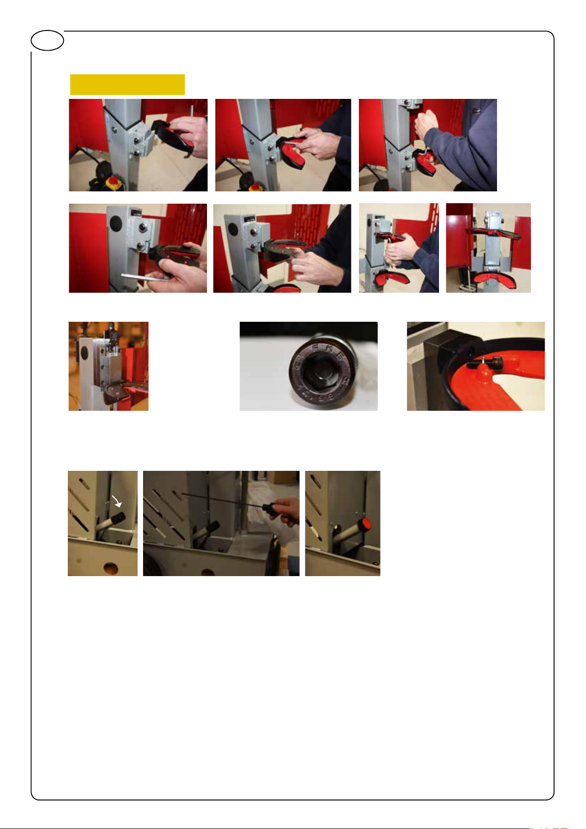
FI
Palkki, jossa alusta
ERITTÄIN TÄRKEÄÄ!
Kiinnitä kahdella M8-pultilla.
Voitele ylempi kiinnityskenkä
(Super Lube® -suihke)
Ennen ensimmäistä käyttökertaa
Poista kuljetussuojus ja korvaa se öljynmittapuikolla
Käytä vain oikeita ruuveja (DIN 912. M10x30, lujuus 14.99)
ja jousialuslevyjä (DIN 7980 M10)
ASENNUS JA KULJETUS
Käyttöpaikan on oltava hyvin valaistu, jotta asennus ja käyttö on turvallista. Käyttöpaikka on
siivottava, eikä siellä saa olla vaarallisia nesteitä lattialla, vaarallisia kulmia viereisissä laitteissa tai
osia, jotka voivat vahingoittaa käyttäjää, jos tämä kaatuu tai kompastuu.
Siirrä CANVIK TITAN -laite painamalla alas kahvaa, kunnes pyörät tukevat jousipuristinta.
Jousipuristinta ei tarvitse kiinnittää.
78
Page 79

KÄYTTÖ
Kierrejousipuristin on tarkoitettu ainoastaan McPherson-jousien puristamiseen ja purkamiseen, ja siinä
on käytettävä sopivia leukoja. Kaikenlaista muuta käyttöä pidetään käyttötarkoituksen vastaisena.
Kiinnitä leuat jousipuristimeen mukana toimitetuilla pulteilla.
Kiristä kuusiopultit hyvin. Turvallisuuden kannalta on erittäin tärkeää, että leukojen pultit on kiristetty
hyvin.
ALOITA KÄYTTÖ liittämällä moottori 230 V:n jännitteeseen. Varmista, että laite on maadoitettu. Paina
hätäpysäytyspainikkeen takana sijaitsevaa vihreää painiketta.
Purista jousi painamalla oikeaa poljinta ja vapauta jousi painamalla vasenta poljinta.
FI
PYSÄYTYS: Vapauta poljin.
HÄTÄPYSÄYTYS:
Paina jousipuristimen vasemmalla puolella olevaa hätäpysäytyspainiketta.
HÄTÄPYSÄYTYS
Jousen kiinnityksen automaattista pysäytystä määrittävään osaan tehdään säätöjä.
79
Page 80

FI
JOUSEN ASENNUS
Jousen asennuksen ensimmäisessä vaiheessa jousen kiinnikkeitä siirretään erilleen, kunnes jouselle
on riittävästi tilaa. Aseta jousi paikalleen. Paina jousta oikealla polkimella, kunnes se pysähtyy
automaattisesti. Jousi on nyt kiinnitetty ja suojaristikko voidaan sulkea ennen jousen puristamista
Poista turvamekanismi käytöstä sulkemalla suojaristikko jousen puristamista varten
JOUSEN IRROTUS
Irrota jousi siirtämällä jousen kiinnikkeitä erilleen, kunnes ne lähes irtoavat jousesta. Tällöin suojaristikko
aukeaa, jousen kiinnikkeet siirtyvät pois ja jousi voidaan irrottaa
KÄYTÖN JATKAMINEN HÄIRIÖN TAI HÄTÄTILANTEEN JÄLKEEN
Kytke hätäpysäytyspainike pois päältä ja paina vihreää painiketta.
YHDYSRAKENTEISET TURVALAITTEET
Liikkuvat osat on suojattu siten, ettei laitteen käyttö aiheuta vaaroja.
Jousta ei voida puristaa, ellei suojaristikko ole suljettuna.
Jousipuristimen käyttö ilman suojaristikkoa ei ole sallittu.
Varmista ennen käyttöä, että suojaristikko on hyvin suljettu jousen asennuksen jälkeen.
Jousipuristimen vasemmalla puolella on hätäpysäytyspainike.
HÄTÄPYSÄYTYS
80
Page 81

KARTIOJOUSET:
Käytä pystyleukaa 90.0060 varmistaaksesi, että jousen keskilinja on samansuuntainen
puristuslaitteeseen nähden. Jos näin ei ole, älä käytä kierrejousipuristinta kartiojousille. Kiinnitä
pystyleuka 90.0060 halkaisijaltaan pienempään jousen päähän.
Turvallisuuden kannalta on erittäin tärkeää, että leuat on kiinnitetty oikein ja pultit
on kiristetty hyvin ennen käyttöä.
PALLOJOUSET:
Käytä pystyleukaa 90.0060 varmistaaksesi, että jousen keskilinja on samansuuntainen
puristuslaitteeseen nähden. Jos näin ei ole, älä käytä kierrejousipuristinta pallojousille. Kiinnitä
pystyleuat 90.0060 jousen molempiin päihin.
Turvallisuuden kannalta on erittäin tärkeää, että leuat on kiinnitetty oikein ja pultit on kiristetty hyvin
ennen käyttöä.
FI
LISÄVARUSTEET
Erikoisleukoja kaikenlaisille jousille:
Leuka ”vastapäiväisille” jousille, ø 145–195 mm 90.0025
Leuka jousille, joiden halkaisija on 140–175 mm 90.0030
Leuka jousille, joiden halkaisija on 180–230 mm 90.0040
Leuka jousille, joiden halkaisija on 80–120 mm 90.0050
Leuka, Ø 80–145 mm:n kartio- ja pallojousille 90.0060
Leuka malleille BMW E39, E46, Renault Megane II ja Toyota Avensis 90.0070
Leuka mallille Mercedes C 90.0080
Leuka malleille Mercedes E ja Renault Megane II 90.0090
Leuat (pari) malleille Peugeot Break, Citroën C15 90.0100
Leuka mallille Chrysler Grand Voyager, ”vastapäiväinen” jousi 90.0120
VARAOSAT
Vakioleuka, ø 80–200 mm, sis. polyuretaaniosan 10.0010
Jalkapoljin 10.0055.01
Vaunun pyörä 10.0055.02
81
Page 82

FI
KUNNOSSAPITO, VIANETSINTÄ JA KORJAUS
SIIVOUS JA JÄRJESTYS
Työasema on pidettävä puhtaana esineistä, jotka voivat haitata käyttäjän vapaata liikkumista ja
jousien siirtämistä puristimeen ja siitä pois. Työaseman ympäristön lattia on puhdistettava esineistä tai
nesteistä, jotka voivat aiheuttaa käyttäjän liukastumisen tai kaatumisen.
HUOLTO JA KUNNOSSAPITO
Sammuta moottori aina ennen huolto- tai kunnossapitotöitä.
Kun huolto- tai kunnossapitotyöt ovat päättyneet, varmista, että suojat ja turvalaitteet ovat paikoillaan
ja toimivat oikein.
Tämän varoituksen laiminlyönti voi aiheuttaa vakavan loukkaantumisen.
Mitä? Milloin? Miten?
Putket Kuukausittain Tarkista, onko näkyviä reikiä
tai vuotoja. Vaihda kuluneet
tai vaurioituneet putket ennen
moottorin käynnistämistä.
Hydrauliöljyn määrä
(Mobil DTE 10 Excel Series)
Hydrauliliittimet Kuukausittain Tarkista mahdolliset murtumat
Leukojen kiinnityspultit Joka käyttökerralla Tarkista, ovatko pultit löysällä.
Pilari Kuukausittain Voitele pilari
Kuukausittain Tarkista, että öljyn määrä on
öljytikun kahden merkin välissä.
Lisää tarvittaessa hydrauliöljyä,
jonka jähmettymispiste on
alhainen.
ja vuodot. Vaihda vaurioituneet
liittimet ennen moottorin
käynnistämistä.
litiumrasvalla.
Liukukenkä
(Super Lube
Liikkuvat osat Kuukausittain Poista mahdollinen lika.
®
Aerosol)
Kuukausittain Voitele liukukenkä rasvalla
TAKUU
Tätä työkalua koskee voimassa olevan lainsäädännön mukainen takuu. Pidätetään oikeus muutoksiin
ilman ilmoitusta.
KÄYTÖN LOPETUS
Laite puretaan, lajitellaan ja hävitetään paikallisten säännösten mukaan.
82
Page 83

Scangrip
DESCRIPTION: Hydraulic vertical coilspring compressor
Low Voltage Directive (LVD), 2006/95/EC
Directive 76/769/EEC and Commission Directives 91/155/EEC, 93/67/EEC, 93/105/EC and 2000/21/EC.
EN 50581:2012
FI
EC Declaration of Conformity
We, Scangrip A/S
Rytterhaven 9
5700 Svendborg, Denmark
Internal Ref. Nr.: ECdoc10.0055
2014
Declare under our responsibility for the product:
Product Range: NAME: Canvik Titan
Product Code: 10.0055
The designated product is in conformity with the essential requirements of the following European
Directives and harmonized standards:
EN 60204-1:2006 Safety of machinery - Electrical equipment of machines - Part 1: General requirements
Electromagnetic compatibility Directive (EMC), 2004/108/EC
EN 55015:2006+A1:2007+A2:2009
The provisions of the machinery Directive (directive 2006/42/ET May 17th2006) and with national implementation legislation
EN ISO12100:2010 Safety of machinery - General principles for design - Risk assessment and risk reduction
REGULATION (EC) No 1907/2006 OF THE EUROPEAN PARLIAMENT AND OF THE COUNCIL of 18 December 2006
concerning the Registration, Evaluation, Authorisation and Restriction of Chemicals (REACH), establishing a European Chemicals Agency,
amending Directive 1999/45/EC and repealing Council Regulation (EEC) No 793/93 and Commission Regulation (EC) No 1488/94 as well as Council
Restriction of the use of certain Hazardous Substances in electrical and electronic equipment Directive (RoHS), 2011/65/EU
28.08.2014 Anders Borring
General Manager
28.08.2014 Nikolaj Poffler
Keeper of technical Documents.
EC Declaration of Conformity, EC DoC
83
Page 84

84FI85FI868788
Page 85

Page 86

Page 87

Page 88

SCANGRIP A/S
RYTTERHAVEN 9
DK-5700
SVENDBORG
DENMARK
WWW.SCANGRIP.COM
SCANGRIP@SCANGRIP.COM
V-2-KE/05.2016
 Loading...