

Page 1
Operating Instructions
Bedienungsanleitung
Instructions d’utilisation
Instrucciones de uso
Betjeningsvejledning
Page 2
For Your Safety
Working safely with this tool is possible only when the
operating and safety information are read completely
and the instructions contained therein are strictly followed.
• Before each use, check the unit for full functional capability. If the
functional capability is not ensured or if damage is detected, the
unit should not be used.
• When compressing the spring, neither the spring windings nor the
jaws should come in contact with each other, Fig.B
• The centre line of the spring must always be parallel to the com-
pressing device, especially for conical springs.
• Use only suitable jaws for the springs. The spring must rest se-
curely within the outer rib and the safety ridges. Take care that sliding of the spring out of the jaws is not possible.
• The bolts of the jaws must always be firmly tightened.
• When using impact wrench do not exceed 180 Nm torque limit.
• For repair, use only original parts.
• Do not make any construction changes to the unit. Do not replace
safety pin by a stronger safety pin.
Use as intended
The coil spring compressor is exclusively for compressing and expanding of
McPherson strut springs whereby suitable jaws must be used. Any other or
further use is considered not as intended.
Page 3
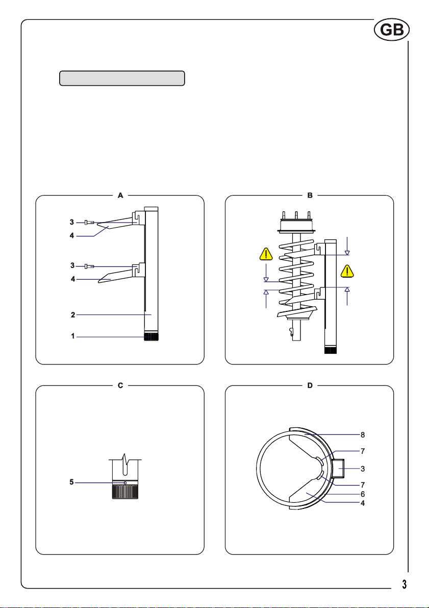
Operating Controls
1 Handle
2 Compressing device
3 Retaining bolts
4 Jaws
5 Safety pin
6 Outer rib
7 Safety ridge
8 Spring
Page 4
Specifications
McPherson Coil Spring Compressor
including 2 multipurpose jaws Ø80-200 mm with polyurethane inserts and a
protective accessory for clamping in vice.
Article no.: 10.0001
Maximum load: 2,500 kg (25,000 N)
Minimum distance between jaws: 40 mm
Maximum distance between jaws: 396 mm
Spring capacity with standard jaws: Ø80-200 mm
Length body: 485 mm
Weight body: 5.9 kg
Weight incl. jaws: 8.5 kg
Standard Accessories:
2 jaws fitting springs diameters of Ø80-200 mm 10.0010
1 protective accessory for vice 10.0020
2 extension units 10.0030
4 extension unit bolts and 2 jaw bolts
Special Accessories
Special purpose jaws delivered on request
Jaw for BMW E39, E46, Renault Megane II and Toyota Avensis 10.0070
Jaw for Mercedes C-class 10.0080
Jaw for Mercedes E-class and Renault Megane II 10.0090
Jaws (pair) for Peugeot Break, Citroën C15 10.0100
Jaw for Chrysler Grand Voyager, “counter clock” spring 10.0120
Page 5
Operation Advice
• Remove the McPherson spring strut.
• Mount the jaws onto the spring compressor. Fit the retaining bolts
and tighten firmly.
It is very important for your safety that the bolts of the jaws
are firmly tightened.
• Rotate the handle to drive the jaws apart to match the length of the
spring and to compress as many windings as possible.
• Place the coil spring compressor with protective accessory in a
suitable vice.
• Place the spring strut onto the coil spring compressor. Take care
that the seating of the spring windings in the jaws is correct.
• With an impact wrench or a racket spanner, turn the handle until the
upper support bearing is free. Additional compressing is permitted.
When using impact wrench do not exceed 180Nm
torque limit.
• Replace the spring strut cartridge and refit the upper support bear-
ing.
• Release the coil spring compressor and remove it.
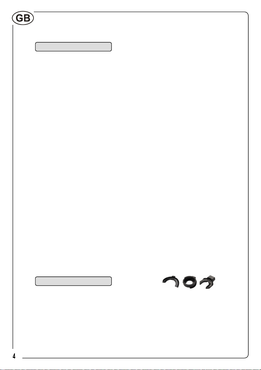
Page 6

Long Springs
Conical Springs
Ball Springs
Long Springs
• Use the included extension units for compressing long springs. The
maximum distance is increased by fitting the extension units with
the 4 special bolts included.
It is very important for your safety that the extension units
and jaws are fitted correctly and that the bolts are firmly
tightened before use.
Conical Springs
• Use the included extension unit to ensure that the centre line of the
spring is parallel to the compressing device. Do not use the coil
spring compressor for conical springs if this is not the case. Fit the
extension unit with included bolt in order to raise the jaw at the
spring end with the smallest diameter.
It is very important for your safety that the extension unit
and the jaws are fitted correctly and that the bolts are firmly
tightened before use.
Ball Springs
• Use the included extension units to ensure that the centre line of
the spring is parallel to the compressing device. Do not use the coil
spring compressor for ball springs if this is not the case. Raise both
jaws by fitting the extension units with the 2 bolts included.
It is very important for your safety that the extension units
and the jaws are fitted correctly ant that the bolts are firmly
tightened before use.
Page 7
Maintenance and Cleaning
• Always keep the unit clean.
• For all inquiries and spare parts ordering, please include the serial
number in all cases.
• Grease the guide spindle if necessary, however at least every six
months. Clean the spindle before greasing.
Recommended grease: graphite grease.
Replacing the Safety Pin, Fig.C.5
• Overloading of the spindle will result in the safety pin breaking.
Whilst the handle will still rotate, the spindle remains in its last position ensuring the spring remains compressed. Replace the safety
pin as described.
• Remove the handle.
• Drive out the broken pin with a drift pin.
• Refit the handle and align the drilling of the spindle and the handle
and drive in a new safety pin (5x30 mm + 3x30 mm, ISO8752).
Guarantee
This tool carries a guarantee according to current law.
Subject to change without notice
Page 8
Zu Ihrer Sicherheit
Gefahrloses Arbeiten mit dem Gerät ist nur möglich,
wenn Sie die Bedienungsanleitung und die Sicherheitshinweise vollständig lesen und die darin enthaltenen
Anweisungen strikt befolgen.
• Vor jeder Benutzung das Gerät auf seine volle Funktionsfähigkeit
untersuchen. Ist die Funktionsfähigkeit nicht gewährleistet oder
werden Schäden festgestellt, darf das Gerät nicht verwendet werden.
• Beim Spannen der Feder dürfen sich die Federwindungen nicht be-
rühren, ebenso wenig die beiden Federhalter, Abb. B
• Die Federmittelachse muss immer parallel zum Spannkörper 2
sein, insbesondere bei konischen Federn.
• Nur geeignete Federhalter für die Federn einsetzen. Die Feder
muss sicher innerhalb der Außenrippe und der Sicherheitswulster
liegen. Achten Sie darauf, dass ein Herausgleiten der Feder aus
den Federhaltern nicht möglich ist.
• Die Schrauben der Federhalter müssen immer festgezogen sein.
• Nur bis zu 180 Nm Druckluftschrauber verwenden.
• Bei Instandsetzung nur Originalteile verwenden.
• Nehmen Sie keine bauartbedingten Veränderungen an dem Gerät
vor. Ersetzen Sie nicht den Spannstift durch einen stärkeren
Spannstift.
Bestimmungsgemäße Anwendung
Der Federbeinspanner ist ausschließlich zum Spannen und Entspannen von
zylindrischen und konischen MacPherson Federbeinen bestimmt, wobei
passende Federhalter verwendet werden müssen. Jede andere oder darüber hinaus gehende Verwendung gilt als nicht bestimmungsgemäß.
Page 9

Geräteelemente
1 Handgriff
2 Spannkörper
3 Schrauben
4 Federhalter
5 Spannstift
6 Außenrippe
7 Sicherheitswulst
8 Feder
Page 10

Gerätekennwerte
MacPherson Federbeinspanner
Komplett mit 2 Federhaltern Ø 80-200 mm mit Polyurethaneinlagen und
Schutzbacke für Schraubstock.
Artikelnummer: 10.0001
Max. Druckkraft: 2.500 kg (25.000 Nm)
Min. Spanntiefe: 40 mm
Max. Spanntiefe: 396 mm
Für Federdurchmesser: Ø80-200 mm
Spannkörperlänge: 485 mm
Grundkörpergewicht: 5.9 kg
Gesamtgewicht (einschl.) Federhaltern: 8.5 kg
Standardzubehör:
2 Federhalter für Federdurchmesser 10.0010
Sonderangefertigte Schutzbacke für Montage im Schraubstock 10.0020
2 Verlängerungsmodule 10.0030
4 Verlängerungsmodule und 2 Schrauben für Federhalter
Sonderzubehör
Spezialfederhalter auf Anfrage
Federhalter für BMW E39, E46, Renault Megane II und Toyota Avensis 10.0070
Federhalter für Mercedes C-Klasse 10.0080
Federhalter für Mercedes E-Klasse und Renault Megane II 10.0090
Federhalter für Peugeot Break, Citroën C15 (wird paarweise geliefert) 10.0100
Federhalter für linksdrehende Feder Chrysler Grand Voyager 10.0120
Page 11
Arbeitshinweise
• MacPherson Federbein ausbauen.
• Federhalter am Federbeinspanner montieren. Schrauben gut an-
ziehen.
Aus Sicherheitsgründen müssen die Schrauben der Federhalter immer festgezogen sein.
• Federhalter entsprechend der Federlänge auseinander fahren, um
möglichst viele Windungen spannen zu können.
• Federbeinspanner mit Schutzbacke in einer geeigneten Spannvor-
richtung befestigen.
• Federbein am Federbeinspanner ansetzen. Auf korrekten Sitz der
Federwindungen in den Federhaltern achten.
• Mit einem Schlagschrauber oder einer Ratsche den Handgriff nach
rechts drehen, bis das obere Stützlager frei ist. Ein weiteres Spannen der Feder ist nicht zulässig.
Nur bis zu 180 Nm Druckluftschrauber verwenden.
Max. Drehmoment
• Feder oder Stoßdämpfer ersetzen und oberes Stützlager wieder
montieren.
• Federbeinspanner entspannen, bis dieser von der Feder genom-
men werden kann.
Page 12

Lange Federn
Konische Federn
Kugelfedern
Lange Federn
• Für lange Federn die mitgelieferten Verlängerungsmodule benut-
zen. Die maximale Spanntiefe wird durch Montage der Verlängerungsmodule mit den 4 Spezialschrauben erhöht.
Vor Gebrauch ist es aus Sicherheitsgründen sehr wichtig,
dass Verlängerungsmodule und Federhalter richtig montiert
sind und alle Schrauben fest angezogen sind.
Konische Federn
• Benutzen Sie die mitgelieferten Verlängerungsmodule, um sicher-
zustellen, dass die Federmittelachse und der Grundkörper parallel
sind. Eine Benutzung des Federbeinspanners an konischen Federn
ist nur zulässig, wenn die Federmittelachse und der Grundkörper
parallel sind. Das Verlängerungsmodul wird mit der Spezialschraube montiert und vergrößert den Abstand zwischen Federhalter und
Grundkörper für die Federseite mit dem kleinsten Durchmesser.
Vor Gebrauch ist es aus Sicherheitsgründen sehr wichtig,
dass Verlängerungsmodule und Federhalter richtig montiert
sind und alle Schrauben fest angezogen sind.
Kugelfedern
• Benutzen Sie die mitgelieferten Verlängerungsmodule, um sicher-
zustellen, dass die Federmittelachse und der Grundkörper parallel
sind. Eine Benutzung des Federbeinspanners an Kugelfedern ist
nur zulässig, wenn die Federmittelachse und der Grundkörper parallel sind. Mit den mitgelieferten Verlängerungsmodulen den Abstand zwischen Federhalter und Grundkörper für beide Federseiten
vergrößern.
Vor Gebrauch ist es aus Sicherheitsgründen sehr wichtig,
dass Verlängerungsmodule und Federhalter richtig montiert
sind und alle Schrauben fest angezogen sind.
Page 13

Wartung und Pflege
• Gerät stets sauber halten.
• Bei allen Rückfragen und Ersatzteilbestellungen bitte unbedingt die
Seriennummer des Gerätes angeben.
• Führungsspindel bei Bedarf einfetten, mindestens jedoch alle 6
Monate. Spindel vor dem Einfetten reinigen.
Empfohlener Schmierstoff: Grafitfett
Den Sicherheitsstift wie folgt ersetzen (siehe Abb. C.5)
• Bei Überlastung der Spindel bricht der Sicherheitsstift. Obwohl der
Handgriff sich immer noch drehen lässt, bleibt der Spindel stehen
und sichert damit die Feder. Den Sicherheitsstift wie folgt ersetzen:
• Handgriff abnehmen.
• Zerbrochenen Stift mittels Dorn austreiben.
• Handgriff wieder aufsetzen, Bohrungen von Spindel und Handgriff
ausrichten und neuen Spannstift (5x30 mm + 3x30 mm, ISO8752)
einschlagen.
Gewährleistungsverpflichtungen
Für dieses Gerät leisten wir Garantie auf Material- und Herstellungsfehler
nach geltendem Recht.
Änderungen vorbehalten
Page 14

Pour votre sécurité
Il n’est possible de travailler en toute sécurité avec cet
outil que lorsque la notice d’utilisation et de sécurité a
été entièrement lue et que les instructions qu’elle
contient sont rigoureusement respectées.
• Avant chaque utilisation, vérifier que l’outil est en état de
fonctionner. Si ce n’est pas le cas ou si un défaut est constaté,
l’outil ne doit pas être utilisé.
• Lors de la compression du ressort, ni les spires du ressort ni les
mâchoires ne doivent entrer en contact les unes avec les autres.
Cf Figure B
• L’axe du ressort doit toujours être parallèle au compresseur, en
particulier pour les ressorts coniques.
• Utiliser uniquement les mâchoires adaptées au ressort. Assurez-
vous que le ressort est correctement positionné dans les
mâchoires. Assurez-vous que le ressort ne peut pas glisser hors
des mâchoires.
• Les vis des mâchoires doivent toujours être fermement serrées.
• Lors de l’utilisation d’une clé à choc ne pas dépasser un couple de
180 Nm
• Pour les réparations, utiliser exclusivement des pièces originales.
• Ne pas apporter de modifications à cet outil. Ne pas remplacer la
goupille de sécurité par une goupille plus résistante.
Utilisation prévue
Le compresseur de ressort est destiné exclusivement à comprimer les
ressorts de suspensions Mc Pherson en utilisant les mâchoires adaptées.
Toute autre utilisation n’est pas conforme à la destination de l’appareil.
Page 15

Composants de l’outil
1 Poignée
2 Corps du compresseur
3 Vis de fixation
4 Mâchoires
5 Goupille de sécurité
6 Nervure extérieure
7 Bourrelet de sécurité
8 Ressort
Page 16

Caractéristiques
Compresseur de ressort pour suspensions Mc Pherson
Incluant 2 mâchoires Ø80-200 mm avec inserts polyurethane et un
accessoire de protection pour serrage dans un étau.
Référence: 10.0001
Capacité Maximale: 2.500 kg (25.000 Nm)
Écartement Minimal entre mâchoires : 40 mm
Écartement Maximal entre mâchoires: 396 mm
Diamètres de ressort acceptés (avec mâchoires standard): Ø80-200 mm
Longueur du corps: 485 mm
Poids du corps seul: 5.9 kg
Poids mâchoires inclues: 8.5 kg
Accessoires standards:
Paire de mâchoires pour ressorts Ø80-200 mm 10.0010
1 Accessoire de protection pour étau 10.0020
2 Blocs d’extension 10.0030
4 vis pour blocs d’extension et 2 vis pour mâchoires
Accessoires spéciaux
Mâchoires spécifiques livrées sur demande
Mâchoire pour BMW E39, E46, Renault Megane II et Toyota Avensis 10.0070
Mâchoire pour Mercedes Classe C 10.0080
Mâchoire pour Mercedes Classe E et Renault Megane II 10.0090
Mâchoire pour Peugeot Break et C15 (paire) 10.0100
Mâchoire pour Chrysler Grand Voyager (ressort anti-horaire) 10.0120
Page 17

Instructions d’utilisation
• Démonter le combiné Mc Pherson.
• Monter les mâchoires sur le compresseur. Serrer fermement les vis
de fixation.
Il est très important pour votre sécurité que les vis de
serrage des mâchoires soient fermement serrées.
• Actionner la molette pour écarter les mâchoires jusqu’à la longueur
correspondant au ressort de façon à comprimer autant de spires
que possible.
• Placer le compresseur avec le patin de protection dans un étau
adapté.
• Placer le ressort dans le compresseur. Assurez-vous que l’assise
des spires du ressort dans les mâchoires est correcte.
• Actionner l’écrou d’entraînement avec une clé pneumatique ou une
clé à cliquet, jusqu’à libérer l’assise supérieure. Il est possible de
compresser davantage.
Lors de l’utilisation de clé ne pas dépasser un couple de
180 Nm.
• Remplacer l’amortisseur et remettre la coupelle d’appui supérieure.
• Relâcher et retirer le compresseur.
Page 18

Ressorts longs
Ressorts coniques
Ressorts sphériques
Ressorts longs
• Utiliser les blocs d’extension pour compresser les ressorts longs.
L’écartement maximal est augmenté en fixant les blocs d’extension
avec les 4 vis spéciales incluses.
Il est très important pour votre sécurité que les blocs
d’extension et les mâchoires soient montés correctement et
que les vis soient fermement serrées.
Ressorts coniques
• Utiliser les blocs d’extension pour assurer que l’axe du ressort soit
parallèle au compresseur. Ne pas utiliser ce compresseur de
ressort si ce n’est pas le cas. Placer le bloc d’extension avec la vis
fournie de façon à écarter la mâchoire située à l’extrémité du
ressort qui a le plus petit diamètre.
Il est très important pour votre sécurité que les blocs
d’extension et les mâchoires soient montés correctement et
que les vis soient fermement
Ressorts sphériques
• Utiliser les blocs d’extension pour assurer que l’axe du ressort soit
parallèle au compresseur. Ne pas utiliser ce compresseur de
ressort si ce n’est pas le cas. Ecarter les deux mâchoires en fixant
les deux blocs d’extension avec les 2 vis incluses.
Il est très important pour votre sécurité que les blocs
d’extension et les mâchoires soient montés correctement et
que les vis soient fermement
Page 19

Maintenance et nettoyage
• Toujours garder l’outil propre.
• Pour toute demande et commande de pièces détachées, veuillez
préciser le numéro de série
• Graisser l’axe au moins tous les six mois ou plus souvent si
nécessaire. Nettoyer l’axe avant de le graisser.
Graisse recommandée: Graisse au graphite.
Remplacement de la goupille de sécurité (figure C5)
• Une surcharge de l’axe provoquera la rupture de la goupille de
sécurité. Alors que l’écrou d’entraînement tournera encore, la tige
filetée restera dans sa dernière position ce qui assure que le
ressort reste compressé. Remplacer la goupille de sécurité comme
indiqué
• Retirer la molette.
• Retirer la goupille cassée avec un chasse-goupille.
• Remonter la molette et aligner les perçages de la tige filetée et de
l’écrou d’entraînement et introduire une nouvelle goupille de
sécurité (5x30 mm + 3x30 mm, ISO8752).
Garantie
Cet outil est garanti selon la loi en vigueur.
Peut être soumis à modifications sans préavis.
Page 20

Para su seguridad
La utilización en toda seguridad de esta maquina será
posible solo cuando las instrucciones de uso y de
seguridad habrán sido leídas y estrictamente
respetadas.
• Antes cada uso, verificar que el articulo esté en buen estado de
funcionamiento. No hay que utilizarlo si se detecta un problema o si
el artículo no tiene su entera capacidad de funcionamiento.
• Durante la compresión del muelle, las espiras del muelle y las
placas de aprieta no tienen que entrar en contacto entre ellas. Cf
Imagen B
• El eje del muelle tiente siempre que estar en paralelo al tensor, en
particular para los muelles cónicos.
• Utilizar únicamente las placas de aprieta adaptadas al muelle.
Asegurarse que el muelle esté correctamente posicionado en las
placas de aprieta. Asegurarse que el muelle no resbale fuera de las
placas de aprieta
• Los tornillos de las placas de aprieta tienen que estar siempre
apretados fuertes.
• Durante la utilización de una llave de impacto no hay que superar
un par de 180 Nm
• Para las reparaciones, hay que utilizar exclusivamente piezas
originales.
• No se tiene que hacer modificaciones a este artículo. No hay que
reemplazar la clavija de seguridad por una más resistente.
Utilización prevista
El tensor de muelle está destinado exclusivamente a comprimir los muelles
de suspensiones Mc Pherson utilizando las placas de aprieta adaptadas.
Toda otra utilización no será conforme al destino del artículo.
Page 21

Componentes del articulo
1 Mango
2 Cuerpo del tensor
3 Tornillo de fijación
4 Placas de aprieta
5 Clavija de seguridad
6 Nervio exterior
7 Reborde de seguridad
8 Muelle
Page 22

Características
Tensor de muelles para suspensiones Mc Pherson
incluye 2 placas de aprieta Ø80-200 mm con insertos poliuretano y un
accesorio de protección para fijación del tensor en un torno.
Referencia: 10.0001
Capacidad Máxima: 2,500 kg (25,000 N)
Separación mínima entre las placas de aprieta: 40 mm
Separación máxima entre las placas de aprieta: 396 mm
Diámetros de muelles aceptados: Ø80-200 mm
Longitud del cuerpo: 485 mm
Peso del cuerpo solo: 5.9 kg
Peso placas de aprieta incluidas: 8.5 kg
Accesorios estándares:
Par de placas de aprieta para muelles Ø80-200 mm 10.0010
1 accesorios de protección para torno 10.0020
2 Bloques de extensión 10.0030
4 tornillos para bloques de extensión
et 2 tornillos para placas de aprieta
Accesorios especiales
Placas de aprieta específicas entregadas por encargo
Placa de aprieta para BMW E39, E46, Renault Megane II et Toyota Avensis 10.0070
Placa de aprieta para Mercedes Classe C 10.0080
Placa de aprieta para Mercedes Classe E et Renault Megane II 10.0090
Placa de aprieta para Peugeot Break et C15 (par) 10.0100
Placa de aprieta para Chrysler Grand Voyager (muelle anti horario) 10.0120
Page 23

Instrucciones de uso
• Desmontar el combinado Mc Pherson.
• Montar las placas de aprieta en el tensor. Apretar muy fuerte los
tornillos de fijación.
Es muy importante para su seguridad que los tornillos de
aprieta de las placas de aprieta estén apretadas irmemente.
• Accionar la moleta para abrir las placas de aprieta hasta la longitud
correspondiente al muelle para poder comprimir las espiras lo más
posible.
• Colocar el tensor con su manguito de protección en un torno
adaptado.
• Colocar el muelle en el tensor. Asegurarse que el asiento de las
espiras del muelle en la placa de aprieta este correcto.
• Accionar la tuerca con una llave neumática o una llave de trinquete
hasta que el asiento superior esté libre. Es posible comprimir más.
Durante la utilización de una llave no hay que sobrepasar
un par de180 Nm.
• Sustituir el amortiguador y colocar de nuevo la copela de aprieto
superior.
• Soltar y quitar el tensor.
Page 24

Muelles largos
Muelles cónicos
Muelles esféricos
Muelles largos
• Utilizar los calces de extensión entregados para comprimir los
muelles largos. La separación máxima esta aumentada cuando se
fijan los calces de extensión con los 4 tornillos especiales incluidos.
Es muy importante para su seguridad que los calces de
extensión y las placas de aprieta estén correctamente
montadas y los tornillos fuertemente apretados.
Muelles cónicos
• Utilizar les calces de extensión para asegurarse que el eje central
del muelle este paralelo al tensor. No hay que utilizar el tensor si no
es el caso. Fijar el calce entregado con el tornillo entregado de
manera a desplazar la placa de aprieta situada en el lado en el
que el muelle tiene el diámetro más pequeño.
Es muy importante para su seguridad que los calces de
extensión y las placas de aprieta estén correctamente
montados, y que los tornillos estén apretados fuertemente.
Muelles esféricos
• Utilizar los calces entregados para que el eje central del muelle
esté paralelo a la carcasa del tensor. No hay que utilizar el tensor si
no es el caso. Desplazar las dos placas de aprieta fijando los
calces con los tornillos entregados.
Es muy importante para su seguridad que los calces de
extensión y las placas de aprieta estén correctamente
montados, y que los tornillos estén apretados fuertemente.
Page 25

Mantenimiento y limpieza
• Tener el artículo siempre limpio.
• Para cada demanda y entrega de piezas, gracias de indicar el
numero de serie.
• Engrasar la varilla roscada si necesario y por lo menos cada seis
meses.
Grasa recomendada: grasa al grafito
Sustitución de la clavija de seguridad (figure C5)
• Una sobrecarga del eje podrá provocar la ruptura de la clavija de
seguridad. Cuando la tuerca dará vuelta, el vástago se quedara en
su ultima posición, lo que asegurara al muelle de estar comprimido.
Sustituir la clavija de seguridad como indicado.
• Quitar la clavija rota con un arranca pasador.
• Montar de nuevo la moleta y los agujeros del vástago y de la tuerca
e introducir una nueva clavija de seguridad (5x30 mm + 3x30 mm,
ISO8752).
Garantía
Este articulo esta garantizado según la leyes en vigor.
Puede esta sometido a modificaciones sin preaviso
Page 26

Sikkerhedsinstruks
For at opnå sikkert arbejde med fjederspænderen bør
denne sikkerhedsinstruks og hele brugsanvisningen
læses grundigt igennem før brug, og de nævnte anvisninger skal overholdes.
• Kontroller fjederspænderen for korrekt funktion, før den tages i
brug. Fjederspænderen må kun benyttes, hvis den fungerer korrekt
og ikke er defekt.
• Fjedervindingerne og de to fjederholdere må ikke berøre hinanden,
når fjederen spændes (fig.B).
• Fjederens midterakse skal altid forløbe parallelt med stammen,
især når der arbejdes med koniske fjedre.
• Benyt kun egnede fjederholdere til fjedrene. Fjederen skal ligge sik-
kert inden for den udvendige ribbe og sikkerhedspunkterne. Sørg
for at fjederen ikke kan glide ud af fjederholderne.
• Skruerne, der fastgør fjederholderne, skal altid være spændte.
• Ved anvendelse af luftnøgle må max. drejningsmoment 180Nm ikke
overskrides.
• Benyt kun originale reservedele, hvis fjederspænderen skal repare-
res.
• Gennemfør ingen konstruktionsmæssige ændringer på fje-
derspænderen. Sikkerhedsstiften må ikke erstattes af en tykkere
sikkerhedsstift.
Anvendelse
Fjederspænderen er udelukkende beregnet til af- og påmontering af fjedre
på McPherson fjederben. Al anden form for brug falder uden for det beregnede anvendelsesområde. Husk, at der altid skal anvendes passende fjederholdere.
Page 27

Maskinelementer
1 Håndhjul
2 Stamme
3 Skruer
4 Fjederholdere
5 Sikkerhedsstift
6 Udvendig ribbe
7 Sikkerhedspunkt
8 Fjeder
Page 28

Tekniske data
McPherson fjederspænder
Leveres komplet med 2 stk. fjederholdere Ø80-200 mm med polyurethaneindlæg samt beskyttelsesbakke til skruestik.
Varenummer: 10.0001
Max. trykkraft: 2.500 kg (25.000 N)
Min. afstand: 40 mm
Max. afstand: 396 mm
Fjederkapacitet med standard fjederholdere: Ø80-200 mm
Længde, fjederspænder: 485 mm
Vægt, fjederspænder: 5,9 kg
Vægt, inkl. fjederholdere: 8,5 kg
Standard tilbehør:
2 stk. fjederholdere til fjederdiameter Ø80-200 mm 10.0010
1 stk. beskyttelsesbakke til skruestik 10.0020
2 stk. modulklodser 10.0030
4 stk. skruer til modulklodser og 2 stk. skruer til fjederholdere
Specialtilbehør
Special fjederholdere leveres efter bestilling
Fjederholder, BMW E39, E46, Renault Megane II og Toyota Avensis 10.0070
Fjederholder til Mercedes C-class 10.0080
Fjederholder til Mercedes E-class and Renault Megane II 10.0090
Fjederholdere (sæt) til Peugeot Break, Citroën C15 10.0100
Fjederholder til Chrysler Grand Voyager, “venstre om” fjeder 10.0120
Page 29

Betjeningsvejledning
• Demonter McPherson fjederbenet.
• Monter fjederholdere på fjederspænderen. Spænd skruerne fast.
Af sikkerhedshensyn er det meget vigtigt, at fjederholderne
monteres korrekt og fastspændes omhyggeligt før brug.
• Ved hjælp af håndhjulet køres fjederholderne længst muligt fra hin-
anden, så der spændes over så mange vindinger som muligt.
• Anbring fjederspænderen i medfølgende beskyttelsesbakke i en
egnet skruestik.
• Monter fjederbenet på fjederenspænderen. Kontroller, at fjedervin-
dingerne er placeret korrekt i fjederholderne.
• Spænd fjederholderne sammen med luftnøgle eller skraldenøgle,
indtil toplejet er frit. Undgå yderligere sammenspænding.
Ved anvendelse af luftnøgle må max. drejningsmoment
180 Nm ikke overskrides.
• Udskift fjeder eller støddæmper og monter toplejet igen.
• Fjederspænderen løsnes og afmonteres.
Page 30

Lange fjedre
Koniske fjedre
Kuglefjedre
Lange fjedre
• Til af- og påmontering af lange fjedre, forlænges føreklodserne ved
hjælp af medfølgende modulklodser. Modulklodserne monteres ved
hjælp af medfølgende 4 specialskruer.
Af sikkerhedshensyn er det meget vigtigt, at modulklodserne
og fjederholderne monteres korrekt og fastspændes omhyggeligt før brug.
Koniske fjedre
• Da fjederspænderen kun må benyttes på koniske fjedre, hvis fjede-
rens midterakse og fjederspænderens stamme er parallelle, anvendes medfølgende modulklods. Modulklodsen monteres ved hjælp af
medfølgende specialskrue, for at forhøje fjederholderen i den ende,
hvor fjederen har den mindste diameter.
Af sikkerhedshensyn er det meget vigtigt, at modulklodsen
og fjedreholderne monteres korrekt og fastspændes omhyggeligt før brug.
Kuglefjedre
• Da fjederspænderen kun må benyttes på kuglefjedre, hvis fjederens
midterakse og fjederspænderens stamme er parallelle, anvendes
medfølgende modulklodser. Modulklodserne monteres ved hjælp af
medfølgende 2 specialskruer, for at forhøje fjederholderne i begge
ender.
Af sikkerhedshensyn er det meget vigtigt, at modulklodserne
og fjedreholderne monteres korrekt og fastspændes omhyggeligt før brug.
Page 31

Vedligeholdelse og pleje
• Fjederspænderen skal altid være ren.
• Det er vigtigt at angive fjederspænderens serienr., hvis der er
Udskiftning af sikkerhedsstift (fig.C.5)
Service og reparation
Scangrip yder garanti og reklamationsret i henhold til gældende lovgivning.
spørgsmål til værktøjet, eller hvis reservedele skal bestilles.
• Smør spindlen efter behov, dog mindst hver 6. måned. Afrens spin-
delen før smøring.
Anbefalet smøring: grafit-fedt
• Sikkerhedsstiften brækker, hvis spindlen udsættes for overbelast-
ning. Spindlen bliver i sin sidste position selvom håndhjulet roteres
– fjederen forbliver altså sammenspændt. Sikkerhedsstiften udskiftes som følger:
• Afmonter håndhjulet.
• Brækket stift uddrives med dorn.
• Monter håndhjulet således, at hullet i håndhjulet passer ud for hullet
i spindlen og slå en ny sikkerhedsstift i (5x30 mm + 3x30 mm,
ISO8752).
Ret til ændringer forbeholdes
Page 32

Page 33

Page 34

Page 35

Parts List
ITEM PART NO DESCRIPTION
2. 10.0001.02 Slider Movable
3. 10.0001.03 Slider Fixed
5. 10.0001.05 Adjustable Handle
9. 10.0001.09 Safety Pin
16. 10.0001.16 Bolt for Jaw
17. 10.0001.17 Special bolt for Extension Unit
18. 10.0030 Extension Unit
19. 87.0001 Multipurpose Jaw
20. 10.0001.20 Polyurethane insert for jaw
10.0001.R Repair Kit Complete including:
Spindle, Safety Pin, Roll Pin, Bearing,
Circlip and Hexagon Castle Nut.
Page 36

Scangrip A/S
Rytterhaven 9
DK-5700 Svendborg
www.scangrip.com
scangrip@scangrip.com
Rev. 1.03
HHH/20.10.2008
 Loading...