

Page 1
UK – Scan 68
ASSEMBLY AND INSTRUCTION MANUAL SCAN 68
CONGRATULATIONS ON YOUR NEW
SCAN WOOD-BURNING STOVE
You have purchased a product by one of Europe’s leading manufacturers of wood-burning stoves, and we are sure that
you will have years of pleasure from your purchase. To make the best possible use of your stove, it is important that
you follow our advice and instructions.
Read through this Assembly and Instruction Manual carefully before you start to assemble your stove.
Page 2
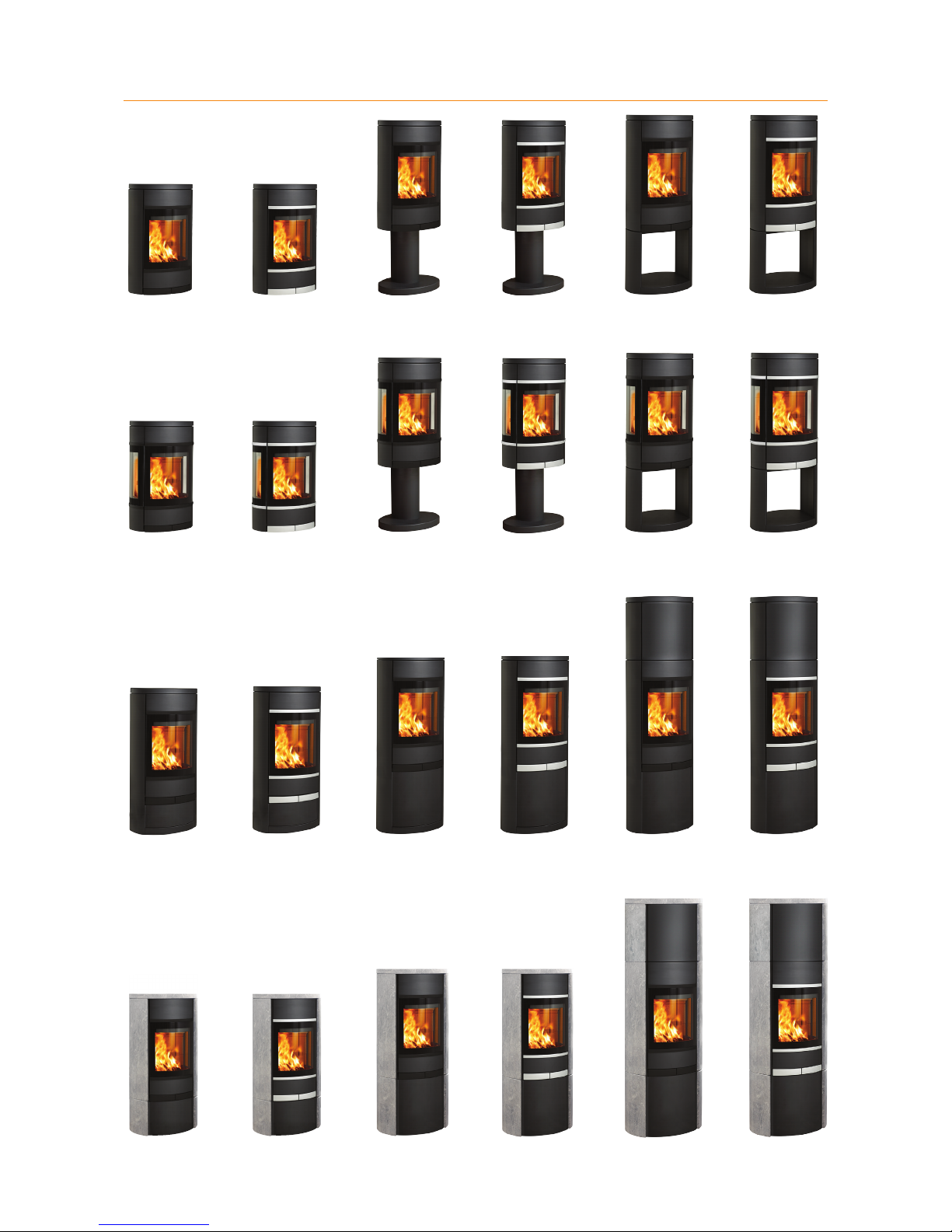
Scan 68-1
Wall hung model
Without side windows
Black mouldings
Scan 68-2
Wall hung model
Without side windows
Aluminium mouldings
Scan 68-3
Pedestal
Without side windows
Black mouldings
Scan 68-4
Pedestal
Without side windows
Aluminium mouldings
Scan 68-5
Portal
Without side windows
Black mouldings
Scan 68-6
Portal
Without side windows
Aluminium mouldings
Scan 68-7
Wall hung model
With side windows
Black mouldings
Scan 68-8
Wall hung model
With side windows
Aluminium mouldings
Scan 68-9
Pedestal
With side windows
Black mouldings
Scan 68-10
Pedestal
With side windows
Aluminium mouldings
Scan 68-11
Portal
With side windows
Black mouldings
Scan 68-12
Portal
With side windows
Aluminium mouldings
Scan 68-13 LB
Low Base
Without side windows
Black mouldings
Scan 68-14 LB
Low Base
Without side windows
Aluminium mouldings
Scan 68-13
Steel sides
Without side windows
Black mouldings
Scan 68-14
Steel sides
Without side windows
Aluminium mouldings
Scan 68-13 HT
High Top
Without side windows
Black mouldings
Scan 68-14 HT
High Top
Without side windows
Aluminium mouldings
Scan 68-15 LB
Low Base
Without side windows
Black mouldings
Scan 68-16 LB
Low Base
Without side windows
Aluminium mouldings
Scan 68-15
Soapstone
Without side windows
Black mouldings
Scan 68-16
Soapstone
Without side windows
Aluminium mouldings
Scan 68-15 HT
High Top
Soapstone
Without side windows
Black mouldings
Scan 68-16 HT
High Top
Soapstone
Without side windows
Aluminium mouldings
SCAN 68-SERIEN
Page 3
TABLE OF CONTENTS
¬
MOUNTING THE UK-SCREW 43
¬
TECHNICAL DATA 4
Installation ....................................................................................... 4
Safety ................................................................................................. 4
Technical data and dimensions ................................................. 4
Dimension ......................................................................................... 5
Type plate........................................................................................11
Product registration number ...................................................12
¬
ASSEMBLY 12
Additional accessories ...............................................................12
Loose parts.....................................................................................12
Disposal of packaging ................................................................12
Removal of packaging ................................................................13
Mounting of the burn chamber on the pedestal basel ....14
Mounting of the burn chamber on the portal basel .........15
Mounting of the door assembly ..............................................16
Mounting of Wall-hung model ..................................................17
Mounting of the wall fitting on the stove ............................18
Removal of the self-closing door spring..............................21
Mounting of external air supply on the wall fitting .........21
Fitting natural stone ...................................................................22
Mounting of high top ...................................................................23
High Top for natural stone ........................................................23
Wall mounting kit for Scan 68 with high top ......................24
Heat-storage stone .....................................................................25
Height adjustment of stove ......................................................26
Connecting piece ..........................................................................26
Existing chimney and pre-fabricated element chimney .27
Connection between stove and steel chimney ..................27
Requirements for chimney .......................................................27
Connection with 90° elbow pipe .............................................27
Load-bearing subsurface ..........................................................28
Floor plate ......................................................................................28
Positioning your wood-burning stove ...................................28
Distance to furniture ..................................................................28
Distance to flammable materials, ..........................................29
Distance to firewall .....................................................................30
¬
INSTRUCTIONS FOR USE 31
CB technology (Clean Burning) ................................................31
Primary air ......................................................................................31
Secondary air .................................................................................31
Baffle plates ..................................................................................31
Ash container .................................................................................31
The Clean Air Act 1993 and Smoke Control Areas ..........31
Refueling on to a low fire bed ..................................................32
Warning about over-firing .........................................................32
Operation with door left open .................................................32
Dampers left open .......................................................................32
Fresh air intake .............................................................................33
Closed combustion system ......................................................33
¬
INSTRUCTIONS FOR HEATING 34
Environmentally-friendly firing ..............................................34
Lighting ............................................................................................34
“Top down” lighting.......................................................................34
Continuous firing ..........................................................................35
Firing in the spring or autumn ..................................................35
The function of the chimney .....................................................35
Using your stove in various weather conditions ...............35
General notes ................................................................................35
Chimney fire ...................................................................................35
¬
HANDLING FUEL 36
Selecting wood/fuel ....................................................................36
Preparation ....................................................................................36
Storing .............................................................................................36
Moisture ..........................................................................................36
Use of the following as fuel is illegal ....................................36
Calorific value of the wood .......................................................36
¬
MAINTAINANCE 37
¬
TROUBLESHOOTING 40
¬
WARRANTY 41
¬
NOTES 42
Page 4
4
TECHNICAL DATA AND DIMENSIONS
Materials
Steel plate
Cast iron
Galvanised sheet
Vermicolite
Surface treatment Senotherm
Max. wood length ca. 33 cm
Weight Scan 68-1/2/7/8 ca. 98 kg
Weight Scan 68-3/4/9/10 ca. 105 kg
Weight Scan 68-5/6/11/12 ca. 107 kg
Weight Scan 68-13/14 ca. 110 kg
Weight Scan 68-13/14 LB ca. 100 kg
Weight Scan 68-15/16 ca. 190 kg
Weight Scan 68-15/16 LB ca. 170 kg
Connecting piece internal diameter 144 mm
Connecting piece external diameter 148 mm
Approval type Intermittent fuelling*
Intermittent operation in this context means normal use
of a wood-burning stove. In other words, you should let
the fire die down until only the embers are left before
refueling.
This stove is produced in accordance with type approval
for the product, which also covers the product’s Assembly
and Instruction Manual.
The Declaration of Performance (DoP) is available from
www.scan.dk
*
PLEASE NOTE!
You get the best use of the stove
by using a top-down lighting.
See "instruction for heating"
TECHNICAL DATA
INSTALLATION
¬ The house owner is responsible for ensuring that installation and assembly are in accordance with national and local
building regulations as well as the information provided in this Assembly and Instruction Manual.
¬ When you install any kind of fireplace or stove, you must inform the local building and housing authorities. In addition
you are obliged to have the installation inspected and approved by a local chimney sweep prior to commissioning.
¬ To ensure best-possible functionality and safety for your installation, we advise you to call a professional fitter. Your
Scan Dealer will be able to recommend a qualified fitter in your area. For information on Scan Dealers, please go to
www.scan.dk.
SAFETY
Any changes made to the product by the dealer, fitter or user could result in the product and safety functions not functioning as intended. The same applies to the fitting of accessories or extra equipment not supplied by Scan A/S. This
could also be the case if parts that are necessary for the operation and safety of the stove are dismantled or removed.
Test in compliance with EN 13240
CO Emission at 13% O
2
0,04 %
CO Emission at 13% O
2
556 mg/Nm
3
Dust @ 13% O
2
14 mg/Nm
3
Nox @ 13% O
2
85 mg/Nm
3
Efficiency 79 %
Energy efficiency index 105,6
Energy efficiency class A
Nominel output 5 kW
Chimney temperature EN 13240 265 °C
Amount of smoke 5,3 g/sek
Sub-pressure EN 13240 12 Pa
Recommended sub-pressure in
connecting piece
17 Pa
Required combustion air supply 16,2 m
3
/h
Fuel Wood
Fuel consumption 1,6 kg/h
Amount of fuel 1,4 kg
Test in compliance with EN 13240
in smoke restricted areas
Efficiency 80 %
Energy efficiency index 107
Energy efficiency class A+
Nominel output 5,5 kW
Page 5

1272
500
192
179
371
611 0*
326***
1255**
350
130*** 220***
250***
794
500
400
371
221
179
400
776**
681*
250***
794
500
400
371
776
681
250
B A
C
1272
500
611 0
326
1255
350
130 220
250
B A
C
C
5
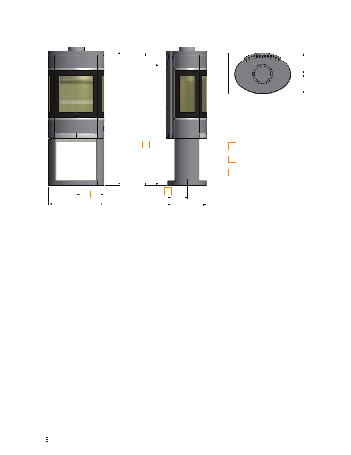
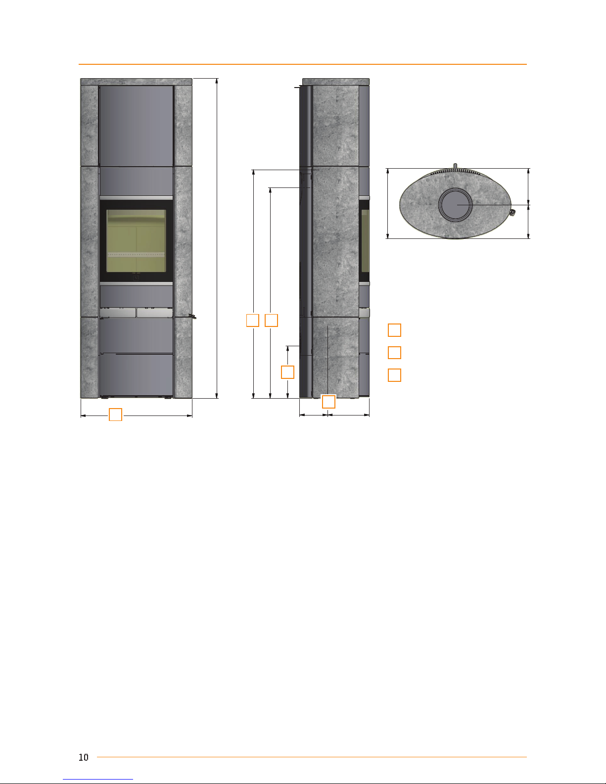
DIMENSION SKETCH SCAN 68-3, 68-4, 68-9 AND 68-10 (PEDESTAL)
DIMENSION
A
Centre rear outlet
B
Height to the beginning of the
connecting piece at top outlet
C
Centre of fresh air intake
All measurements are in millimeters
A
Centre rear outlet
B
Height to the beginning of the
connecting piece at top outlet
C
Centre of fresh air intake
All measurements are in millimeters
SCAN 68-1, 68-2, 68-7 AND 68-8 (WALL HUNG MODEL)
Page 6
1222
500
250***
371
192
179
1110*
1205**
350
175***
1110
1205
350
175
1222
500
250
1110
1205
350
175
B A
C
C
6
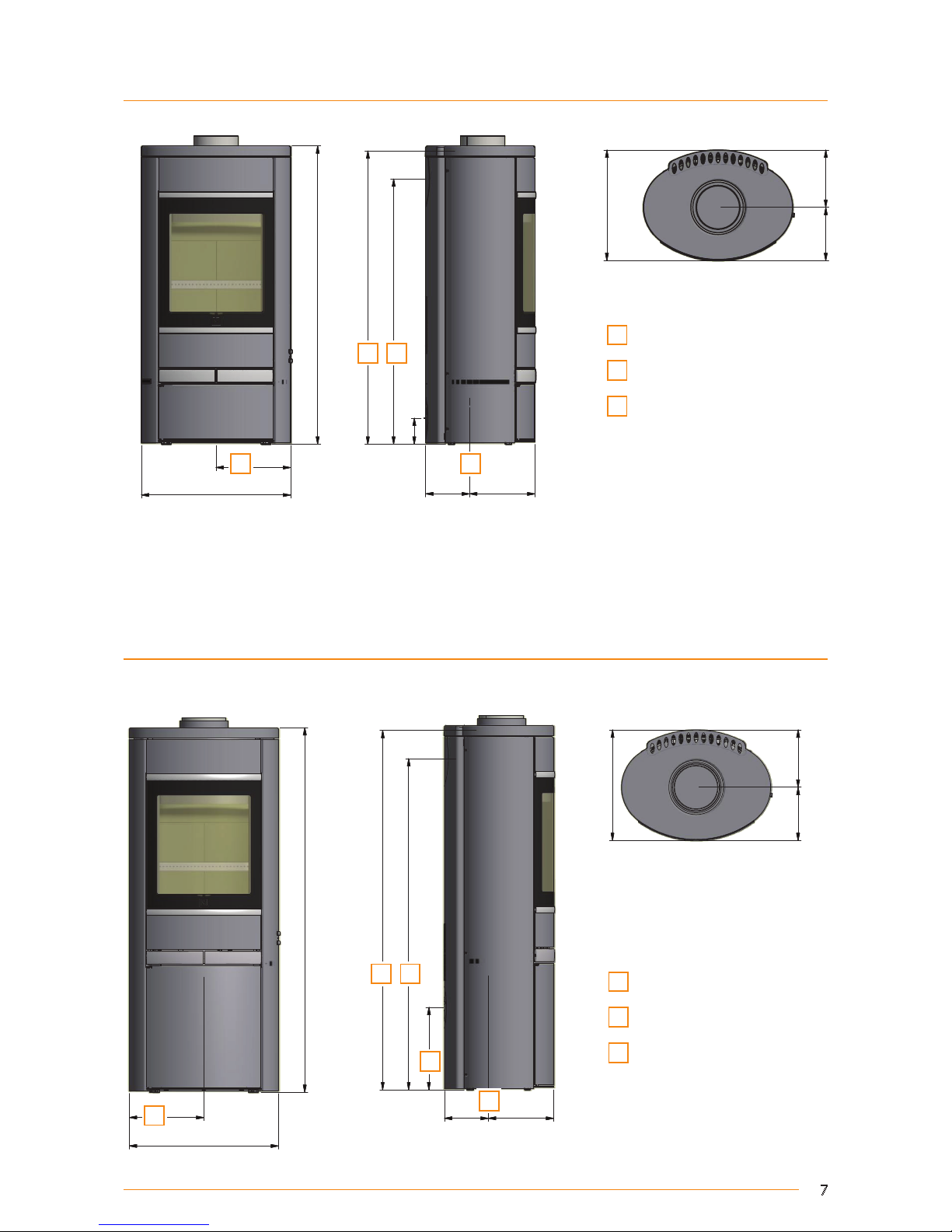
DIMENSION SKETCH SCAN 68-5, 68-6, 68-11 AND 68-12 (PORTAL)
A
Centre rear outlet
B
Height to the beginning of the
connecting piece at top outlet
C
Centre of fresh air intake
All measurements are in millimeters
Page 7
1222
500
371
192
179
1110*
1205**
219***
147***
276***
250***
1110
1205
219
147
276
1222
500
1110
1205
219
147
276
250
B A
C
C
C
500
250***
3
7
1
1
7
9
1
9
2
1
0
0
0
8
8
9
*
9
8
3
*
*
147***
219***
8
8
500
250
1
0
0
0
8
8
9
9
8
3
147
219
8
8
B A
C C
7
DIMENSION SKETCH 68-13 AND 68-14 (STEEL SIDES)
DIMENSION SKETCH SCAN 68-13 AND 68-14LB (LOW BASE)
A
Centre rear outlet
B
Height to the beginning of the
connecting piece at top outlet
C
Centre of fresh air intake
All measurements are in millimeters
A
Centre rear outlet
B
Height to the beginning of the
connecting piece at top outlet
C
Centre of fresh air intake
All measurements are in millimeters
Page 8
1650
371
276
1110*
1205**
250***
147***
179
192
366
1650
276
1110
1205
250
147
366
B A
C
C
8
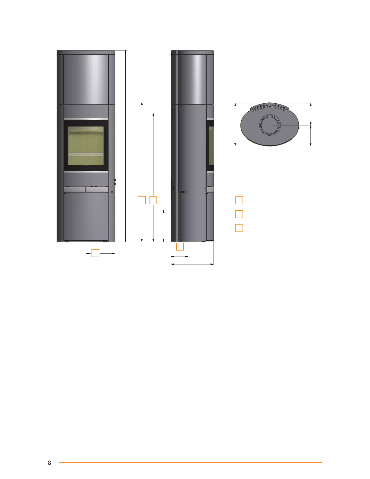
DIMENSION SKETCH SCAN 68-13 AND 68-14 HT (HIGH TOP)
A
Centre rear outlet
B
Height to the beginning of the
connecting piece at top outlet
C
Centre of fresh air intake
All measurements are in millimeters
Page 9
1
2
5
7
586
3
7
1
1
9
2
1
7
9
1
2
0
5
1
1
1
0
2
7
6
147
219
1
2
5
7
586
1
2
0
5
1
1
1
0
2
7
6
147
219
B A
C
C
500
250***
3
7
1
1
7
9
1
9
2
1
0
0
0
8
8
9
*
9
8
3
*
*
147***
219***
8
8
1
0
3
5
586
294
219
147
8
8
889
983
B A
C
C
9
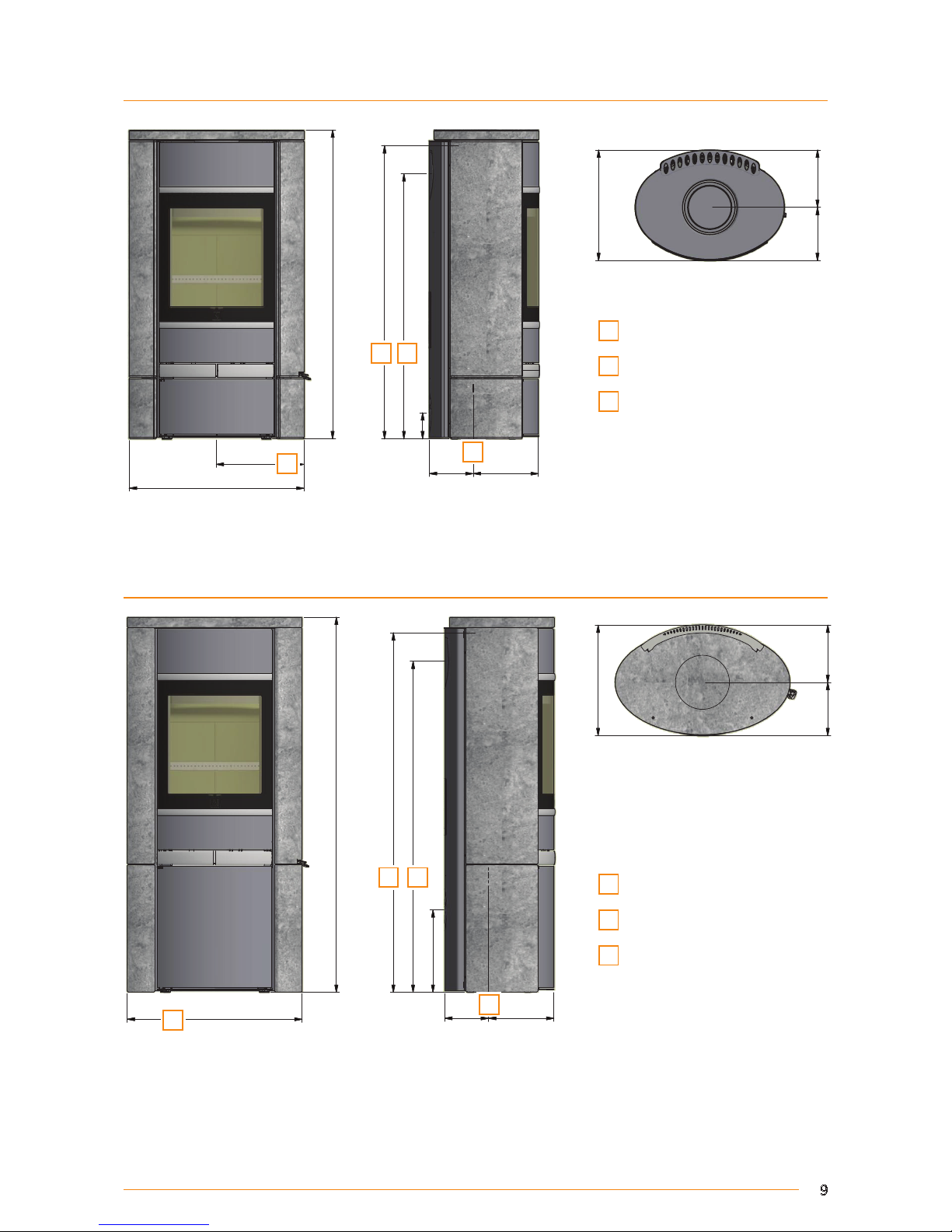
DIMENSION SKETCH SCAN 68-15 AND 68-16 (SOAPSTONE)
DIMENSION SKETCH SCAN 68-13 AND 68-14 (SOAPSTONE + LOW BASE)
A
Centre rear outlet
B
Height to the beginning of the
connecting piece at top outlet
C
Centre of fresh air intake
All measurements are in millimeters
A
Centre rear outlet
B
Height to the beginning of the
connecting piece at top outlet
C
Centre of fresh air intake
All measurements are in millimeters
Page 10
1
6
8
5
586
1
2
0
5
1
1
1
0
2
7
6
147
219
3
7
1
1
9
2
1
7
9
1
6
8
5
586
1
2
0
5
1
1
1
0
2
7
6
147
219
B A
C
C
C
10
DIMENSION SKETCH SCAN 68-15 AND 68-16 HT (SOAPSTONE + HIGH TOP)
A
Centre rear outlet
B
Height to the beginning of the
connecting piece at top outlet
C
Centre of fresh air intake
All measurements are in millimeters
Page 11
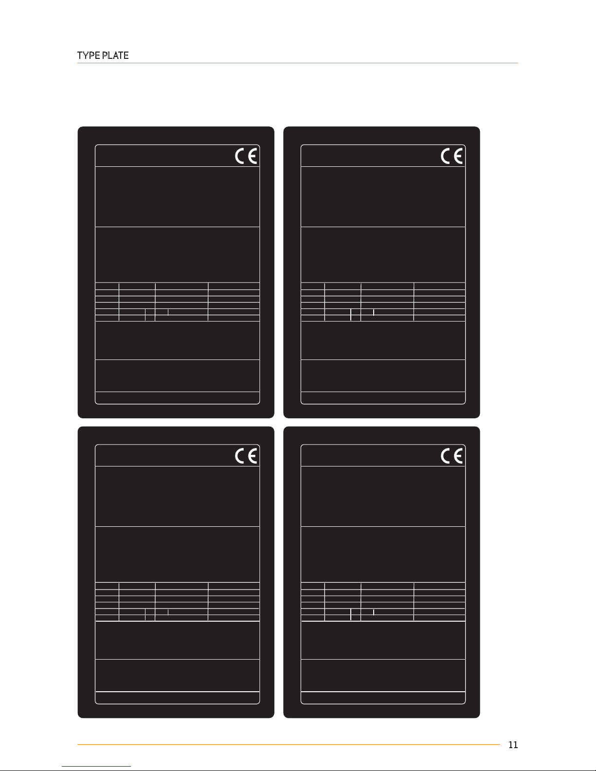
Scan 68-7 and 68-8
Wall mounted room heater fired by solid fuel
Standard:
Fuel type:
Operation type:
The appliance can be operated in a shared flue.
Country
EN 13240 DoP 90068601
Wood
Intermittent
EUR
Norway
Austria
Classification
Intermittent
15a B-VG
Certificate/Standard
EN 13240
NS 3058
ELAB-2100-AUS
Approved by
Teknologisk Institut
Teknologisk Institut
Teknologisk Institut
Dust at 13% O2: 14 mg/Nm³
Flue gas temperature: 265°C
Nominal heat output: 5,5 kW
Efficiency: 80%
Scan A/S DK 5492 Vissenbjerg
Minimum distance to combustible materials
Do not install on combustible materials
Side: 500 mm - Front: 950 mm
CO emission at 13% O2:
Follow assembly- and instructions manual.
Use only recommended fuels.
Montage- und Bedienungsanleitung beachten.
1000 04-2015
0,04% 556 mg/Nm³
Schweiz
Germany
LRV 11
Stufe 2
VKF
1. BlmSchV
Scan 68-3-4-5-6-13-14-15-16
Freestanding room heater fired by solid fuel
Standard:
Fuel type:
Operation type:
The appliance can be operated in a shared flue.
Country
EN 13240 DoP 90068602
Wood
Intermittent
EUR
Norway
Austria
Classification
Intermittent
15a B-VG
Certificate/Standard
EN 13240
NS 3058
ELAB-2100-AUS
Approved by
Teknologisk Institut
Teknologisk Institut
Teknologisk Institut
Dust at 13% O2: 14 mg/Nm³
Flue gas temperature: 265°C
Nominal heat output: 5,5 kW
Efficiency: 80%
Scan A/S DK 5492 Vissenbjerg
Minimum distance to combustible materials
Side: 400 mm - Back: 150 mm - Front: 1100 mm
CO emission at 13% O2:
Follow assembly- and instructions manual.
Use only recommended fuels.
Montage- und Bedienungsanleitung beachten.
1000 04-2015
0,04% 556 mg/Nm³
Schweiz
Germany
LRV 11
Stufe 2
VKF
1. BlmSchV
Scan 68-1 and 68-2
Wall mounted room heater fired by solid fuel
Standard:
Fuel type:
Operation type:
The appliance can be operated in a shared flue.
Country
EN 13240 DoP 90068600
Wood
Intermittent
EUR
Norway
Austria
Classification
Intermittent
15a B-VG
Certificate/Standard
EN 13240
NS 3058
ELAB-2100-AUS
Approved by
Teknologisk Institut
Teknologisk Institut
Teknologisk Institut
Dust at 13% O2: 14 mg/Nm³
Flue gas temperature: 265°C
Nominal heat output: 5,5 kW
Efficiency: 80%
Scan A/S DK 5492 Vissenbjerg
Minimum distance to combustible materials
Do not install on combustible materials
Side: 400 mm - Front: 1100 mm
CO emission at 13% O2:
Follow assembly- and instructions manual.
Use only recommended fuels.
Montage- und Bedienungsanleitung beachten.
1000 04-2015
0,04% 556 mg/Nm³
Schweiz
Germany
LRV 11
Stufe 2
VKF
1. BlmSchV
Scan 68-9-10-11-12
Freestanding room heater fired by solid fuel
Standard:
Fuel type:
Operation type:
The appliance can be operated in a shared flue.
Country
EN 13240 DoP 90068603
Wood
Intermittent
EUR
Norway
Austria
Classification
Intermittent
15a B-VG
Certificate/Standard
EN 13240
NS 3058
ELAB-2100-AUS
Approved by
Teknologisk Institut
Teknologisk Institut
Teknologisk Institut
Dust at 13% O2: 14 mg/Nm³
Flue gas temperature: 265°C
Nominal heat output: 5,5 kW
Efficiency: 80%
Scan A/S DK 5492 Vissenbjerg
Minimum distance to combustible materials
Side: 500 mm - Back: 150 mm - Front: 950 mm
CO emission at 13% O2:
Follow assembly- and instructions manual.
Use only recommended fuels.
Montage- und Bedienungsanleitung beachten.
1000 04-2015
0,04% 556 mg/Nm³
Schweiz
Germany
LRV 11
Stufe 2
VKF
1. BlmSchV
11
TYPE PLATE
All Scan wood-burning stoves are fitted with a type plate that specifies the approval standards and the distance to flammable materials.
The type plate is located at the rear of the stove.
Typeplates
Page 12
6800000
12
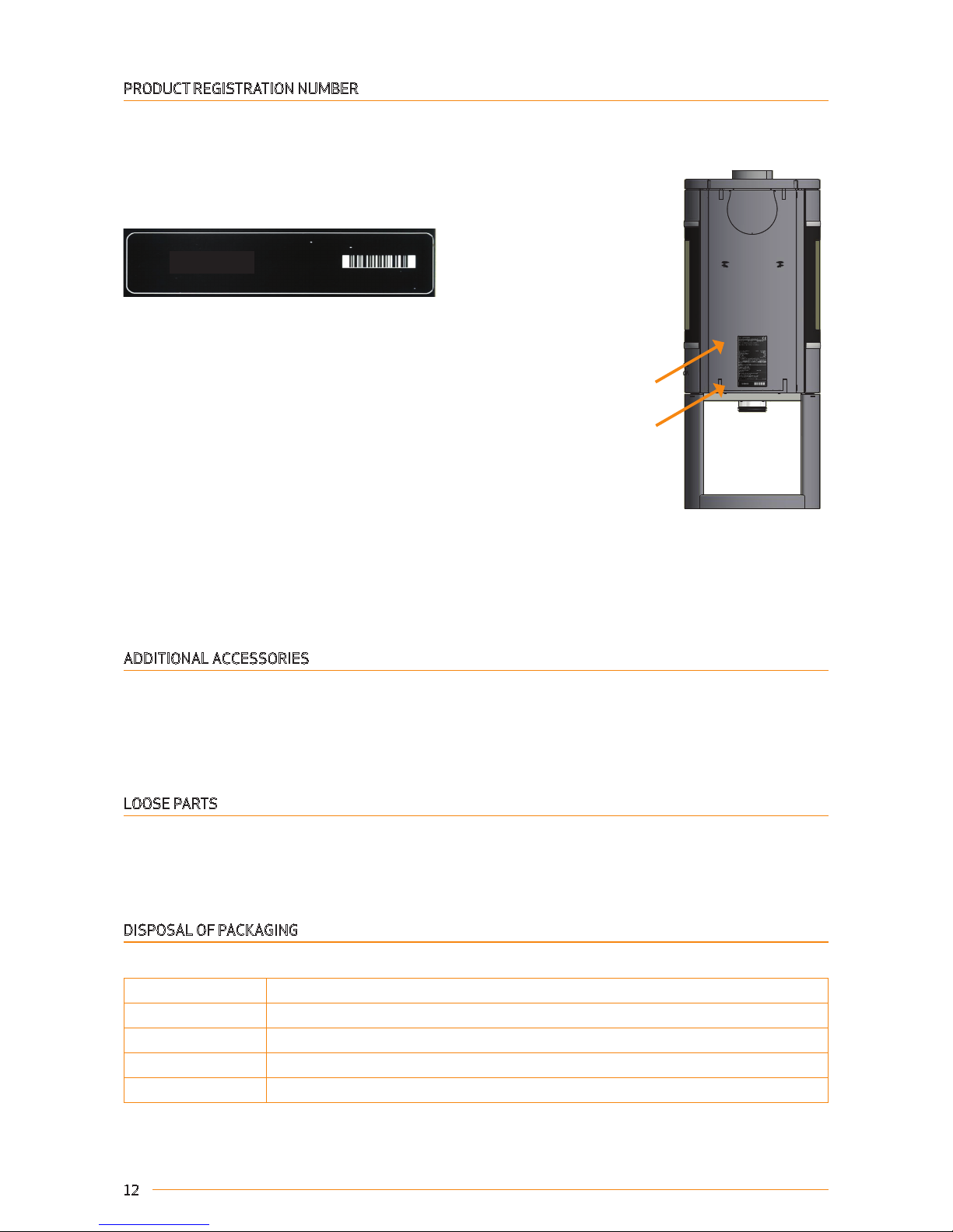
PRODUCT REGISTRATION NUMBER
All Scan wood-burning stoves are provided with a product registration number. You will always need to quote this number
when contacting your dealer or Scan A/S.
The product registration number is located at the rear of the stove.
ADDITIONAL ACCESSORIES
¬ Small shaped floor plate in glass or steel ¬ High Top (Scan 68-13/14)
¬ Large shaped floor plate in glass or steel ¬ High Top (Scan 68-15/16)
¬ Storage door for the Portal unit. ¬ Heat accumulating stones for high top
¬ Connecting piece for inside flue pipe, 6" ¬ Wall mounting kit for Scan 68 with high top
LOOSE PARTS
¬ Glove ¬ Dekor ring for top outlet
¬ Connecting piece 6" ¬ 4 Screw M5 x 10 mm
¬ Seal ¬ 1 Pass Screw M5 x 10 mm (UK) - Please see instructions
DISPOSAL OF PACKAGING
Your Scan stove may come supplied with the following packaging:
Wood packaging Wood packaging: after final use can be incinerated as a CO2 neutral product or sent for recycling
Flamingotop Send for recycling or waste disposal
Foam Send for recycling or waste disposal
Plastic bags Send for recycling or waste disposal
Stretch/plastic film Send for recycling or waste disposal
ASSEMBLY
Type plate
Product registration number
Product registration number
Page 13
B
41
2
3
5
13
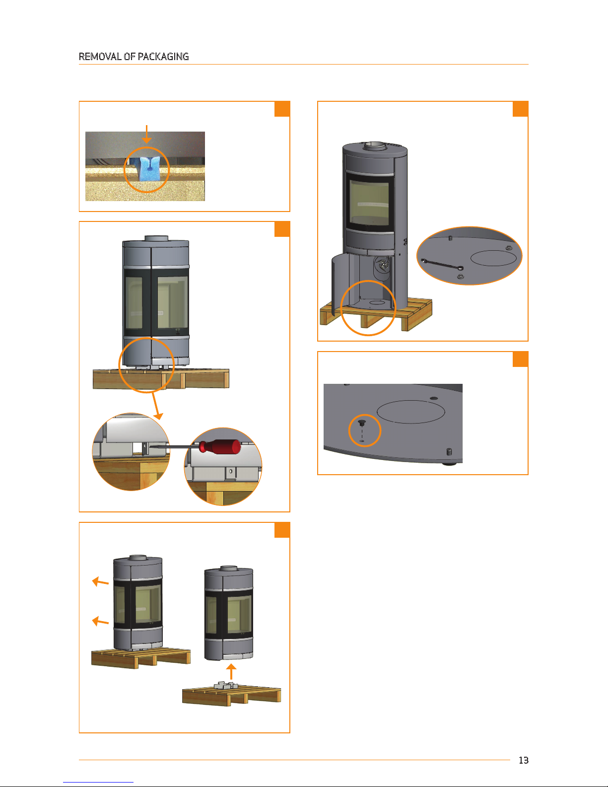
REMOVAL OF PACKAGING
Check that the stove is not damaged before starting to install it.
Pull back and lift.
Please remove protection
The plastic plugs are mounted in the transport
safety holes.
Remove the two screws in the wood compartment
and lift the stove off the pallet.
Page 14
A ( 1 : 5 )
A ( 1 : 5 )
A ( 1 : 5 )
1 2
14
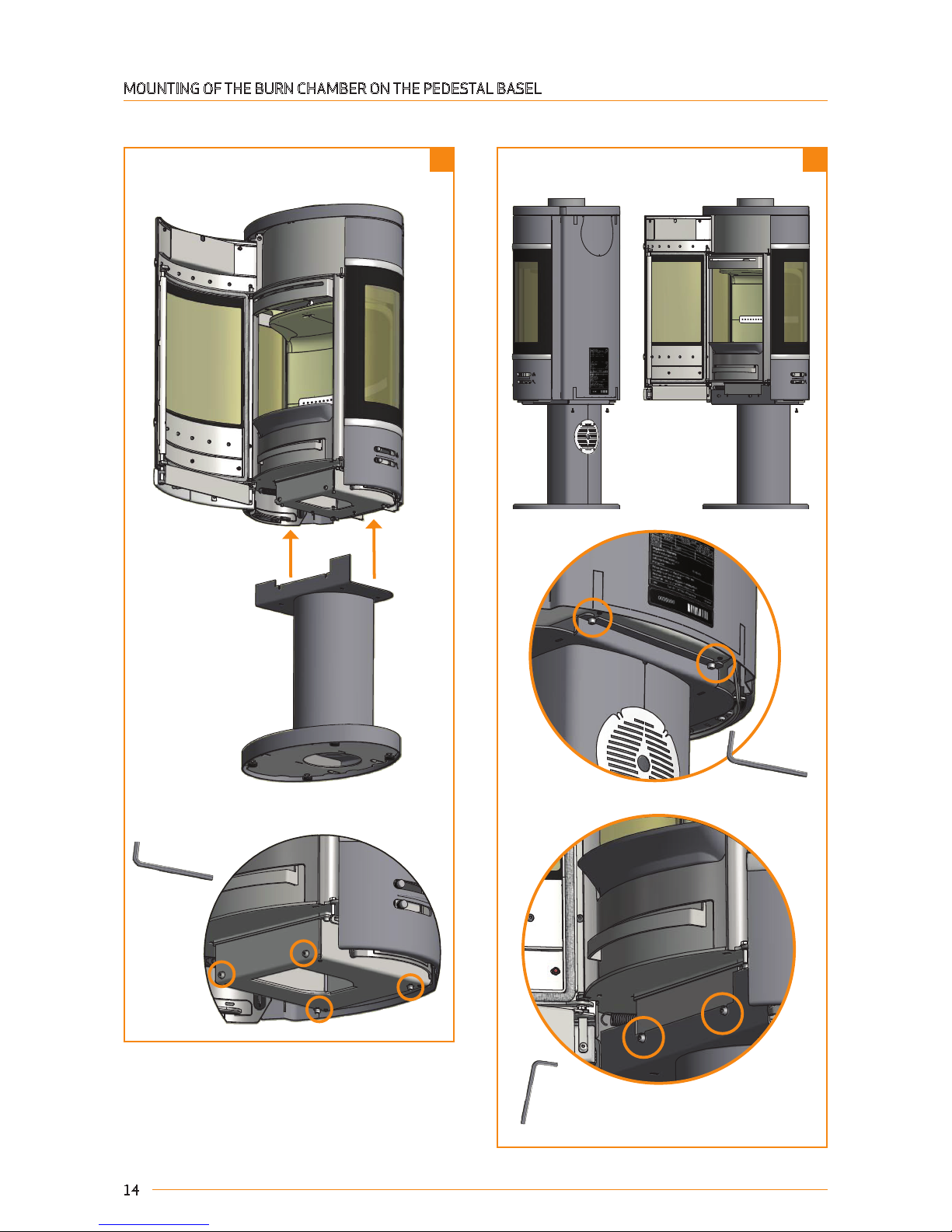
The stove is delivered with the screws mounted.
These must be removed before mounting the base.
MOUNTING OF THE BURN CHAMBER ON THE PEDESTAL BASEL
When the stove has been placed on the base,
the four screws must be remounted.
Page 15

A ( 1 : 5 )
1 2
15
The stove is delivered with the screws mounted.
These must be removed before mounting the base.
MOUNTING OF THE BURN CHAMBER ON THE PORTAL BASEL
When the stove has been placed on the base,
the four screws must be remounted.
Page 16

NAVN:
STI:
DIM.:
MATERIALE:
C:\Working Folder\Designs\Bygningsdele\Skruetrækker.ipt
Plade, st. 240
AREAL:
M3 NR.:
3
1 2
5
6 7
4
16
MOUNTING OF THE DOOR ASSEMBLY
Remove the four screws under
the stove before placing the
door assembly.
Remount the door.The 4 outer screws at the
bottom are easily tightened.
Carefully push the door
assembly in from behind.
Dismount the door.First mount the four
screws at the top.
Dismount the door.
Page 17

Scan 68-7 and 68-8
Wall mounted room heater fired by solid fuel
Standard:
Fuel type:
Operation type:
The appliance can be operated in a shared flue.
Country
EN 13240 DoP 90068601
Wood
Intermittent
EUR
Norway
Austria
Classification
Intermittent
15a B-VG
Certificate/Standard
EN 13240
NS 3058
ELAB-2100-AUS
Approved by
Teknologisk Institut
Teknologisk Institut
Teknologisk Institut
Dust at 13% O2: 14 mg/Nm³
Flue gas temperature: 265°C
Nominal heat output: 5,5 kW
Efficiency: 80%
Scan A/S DK 5492 Vissenbjerg
Minimum distance to combustible materials
Do not install on combustible materials
Side: 500 mm - Front: 950 mm
CO emission at 13% O2:
Follow assembly- and instructions manual.
Use only recommended fuels.
Montage- und Bedienungsanleitung beachten.
1000 04-2015
0,04% 556 mg/Nm³
Schweiz
Germany
LRV 11
Stufe 2
VKF
1. BlmSchV
17
Is only to be removed for external air supply
Replace with the inclosed
Type plate
Must be removed, also in the
heat shield, for wall fitting
Must be removed for wall fitting
MOUNTING OF WALL-HUNG MODEL
Installation must be planned and executed in accordance with national and local building regulations.
The stove must only be fitted to a non-flammable wall. There must be no form of flammable component in the wall. In the
case of thin walls, nor must there be any behind the wall. The load-bearing capacity of the wall must be checked under all
circumstances.
To ensure correct installation we recommend that a building expert be commissioned to plan and outline the installation
with a view to subsequent approval.
For wall installation we recommend using the wall brackets supplied.
If a chimney is installed on top of a wall-hung model, the chimney must be fully self-supporting. It must not rest on the
wood-burning stove. There must be a distance of at least 6 mm between the first section and the flange on the flue collar.
Please consult a specialist.
Scan A/S disclaims all liability for the installation of wall-hung wood-burning stoves.
Use either a drilling machine with Ø 6 mm drill or
cutting nippers to remove the illustrated plates
Page 18

C ( 1 : 2 )
C
C ( 1 : 2 )
DATO:
SIGN:
Scan A/S
DK-5492 Vissenbjerg
©
TG.NR:
EMNE:
Unbrako 4mm
27-04-2007 BC
VÆGT:
AREAL:
N/A
N/A
3
41
2
5
6
18
In order to mount the wall fitting to a chimney made of Leca-blocks you need 6 pcs. FBS
8x70/5 US Leca screws.
The test report can be required at Scan A/S.
When the two screws have been removed,
you can lift the guide plate and put the fitting
underneath.
MOUNTING OF THE WALL FITTING ON THE STOVE
Fasten the fitting with two screws.
Remount the guide plate with the two screws.
Remove the top plate.
Remove the two screws as shown below.
Mount the top plate and the decor grid.
Page 19

Min. 430 mm
511 mm
677,5 mm
169 mm
x x
NAVN:
7 8
10
9
19
Draw a vertical line on the wall
(you can use a spirit level).
Use this line for the mounting of the wall fitting.
Measure from the vertical line and drill the holes.
Use the guide blocks to hold the wall fitting while
adjusting it.
Use the line or a spirit level.
Drill the necessary holes and mount the screws.
(Continued on next page)
Mount the two guide blocks.
Page 20

430
11
12
13
14
20
Now the stove is ready to be mounted on the wall fitting.
Hook the stove on the wall fitting..
Mount screw and disc.
If you want an external air supply, it should be mounted now. (See instructions in this manual).
The two screws under the stove must be removed,
before lifting the stove up on the wall fitting.
When the stove is in position, mount the two
screws in the bottom and the loose decor grate
on the top.
If you want a rear outlet, see page 26 in this manual.
Page 21

21
If you DO NOT want an external air supply, remove
the round plate with cutting nippers in order to
ensure an air flow.
If you want external air supply from the bottom, mount
the connecting piece.
MOUNTING OF EXTERNAL AIR SUPPLY ON THE WALL FITTING
If you do not want an external air supply, it is not necessary to mount the duct tube or the connecting piece.
Please note that the gasket is
to be placed in the slot.
REMOVAL OF THE SELF-CLOSING DOOR SPRING
The stove is born with a spring that makes the door close automatically. This spring can easily be removed with a nipper.
Bottom view
Page 22

A ( 1 : 2 )
B ( 1 : 5 )
B
22
FITTING NATURAL STONE
Scan 68-15 and Scan 68-16 are supplied with loose pieces of natural stone that are fitted to the sides of the stove.
Natural stone is made from a natural material and consequently its pattern and shape may vary.
Please note that the illustration shows a High Top, which can be purchased as an accessory.
Sealing strip
Marking hole
Trim the sealing strip supplied so that it
fits in between the two marking holes.
Fix the stove to the inside of the marking holes as shown above.
Fix the stones to the
stove and the decorative grate and then
place the top plate
loosely on top.
PLEASE NOTE that the bottom damper handle
(match) should be moved to position B so there is
enough room to fit the stone at the bottom.
Page 23

A ( 1 : 5 )
A
31
1 2
2
23
Re-fit the front plate.
Fit the two bottom screws so the front
plate can be pushed in between when it
is mounted.
Re-tighten the two bottom screws
once the front plate is in place.
MOUNTING OF HIGH TOP
If you choose to connect the stove with an elbow pipe or a rear outlet, the stove must be mounted to the wall behind the
oven using a special wall mounting kit. This kit can be purchased from your local Scan dealer. For fitting, see instructions
in this manual.
IT IS VERY IMPORTANT THAT THE BASE IS LEVEL AND STABLE.
The front plate of the high top is removed as
follows:
Remove the Allen screws. Remove the front of the
high top.
HIGH TOP FOR NATURAL STONE
A sealing strip, four M5x10 screws with flange and four spacer bushes are supplied.
Remove the top plate.
Remove the 6 rubber grommets.
Spacer bush
Use the six screws that are
supplied with the High Top.
(M5 x 10).
Fit the four spacer bushes
supplied before fixing the High
Top in place.
Page 24

STYKLISTE
STKDATOBESKRIVELSETEGNPOS
114-02-11
Prop for wireb
øsning
603580281
117-05-10
Hus for wirebøsning
603580292
119-05-10
Sikringswire for Høj Top
603580303
1
2
A ( 1 : 5 )
24
WALL MOUNTING KIT FOR SCAN 68 WITH HIGH TOP
If you choose to connect the stove with an elbow pipe or a rear outlet, the stove must be mounted to the wall behind the
oven using a special wall mounting kit. This kit can be purchased from your local Scan dealer
See instructions in this manual for how to fit the high top.
Fit the wall mounting kit before connecting the stove to the chimney.
IT IS IMPORTANT THAT THE STOVE IS MOUNTED SECURELY TO THE WALL USING THE RIGHT FIXINGS FOR THE SPECIFIC
TYPE OF WALL.
Casing for wire bushing is fixed to the wall
Fasten the safety wire and the wire bushing to the
wire bushing casing using a pointed screw.
Fasten the safety wire to the high top with a
nipple screw.
Safety wire
Casing for wire bushing
Fix to the wall using the
right fixings for the
specific type of wall.
Wire bushing
Pointed screw
M4x5
Nipple screw
Ø8x12.5
Page 25

1
2
1 2 3
3
25
The heat accumulating stones
are placed in the high top and
turned in place around the
chimney
The second stone is placed
next to the first stone so that
they join each other around the
chimney
The rest of the stones are
placed in the same way
Fixing hole for fastening the safety wire in the high top
with rear outlet. (1)
Fixing hole for fastening the safety wire in the high top
with elbow pipe. (2)
HEAT-STORAGE STONE
Heat-storage stones are made from a special material with a high heating capacity. The stones are heated up during the
firing and gives off the heat again after the firing, which means that the stove stays warm for a longer time.
Firing with the vent open will give a quicker heating. Firing with the vent closed will extend the heating time of the stove.
Page 26

Ø 6 mm
26
HEIGHT ADJUSTMENT OF STOVE
The Scan 68 has four adjustment screws under the stove.
Use the adjustment screws to get the stove to stand straight and
level.
Tilt the wood-burning stove and adjust the adjustment screws.
If you are using a shaped floor plate, you should adjust the stove
upwards to allow the plate to be inserted under the front of the
stove.
CONNECTING PIECE
The stove is prepared from the factory for top
outlet.
TOP OUTLET REAR OUTLET
Page 27

27
EXISTING CHIMNEY AND PRE-FABRICATED ELEMENT CHIMNEY
If you intend to connect your stove to an existing chimney, it makes sense to contact an authorised Scan dealer, or a local
chimney sweep, for advice. These experts will also let you know if your chimney needs renovating.
¬ When connecting a pre-fabricated element chimney, follow the manufacturer’s connection instructions for the relevant
chimney type.
CONNECTION BETWEEN STOVE AND STEEL CHIMNEY
Your Scan dealer, or local chimney sweep, can advise you on choosing a make and type of steel chimney (we recommend
using JØTUL’s chimney system). This ensures that the chimney will match your wood-burning stove. As a general rule, the
length of the chimney should not be less than 4 metres, measured from the top of the stove. Specific weather or installation conditions might require a different length.
¬ Choosing the wrong length or diameter of steel chimney could impair functionality.
¬ Always observe the chimney vendor‘s instructions precisely.
REQUIREMENTS FOR CHIMNEY
The chimney must be labelled T400 and G for soot testing.
CONNECTION WITH 90° ELBOW PIPE
If you opt to connect the stove with an elbow pipe, you should use a curved elbow, as this gives a better draught.
Page 28

28
Small shaped floor plate in glass or steel. Large shaped floor plate in glass or steel
LOAD-BEARING SUBSURFACE
All items in our product range come under the category of lightweight fireplaces and stoves and do not normally require
any reinforcement of the beam structure. They can be positioned on ordinary beams/floor.
However, you should make sure that the load bearing underlay can bear the weight of the wood-burning stove and that of
the chimney.
FLOOR PLATE
If you are erecting the stove on a flammable floor, you must comply with the national and local regulations on the size of
any non-flammable subsurface required to cover the floor around the stove.
Your local Scan dealer can advise you on regulations concerning protection of flammable materials in the vicinity of your
stove.
The floor plate’s function is to protect the floor and flammable material against any sparks that may occur.
A floor plate can be made of steel or glass, but the stove can also be erected on clinker concrete, natural stone or similar
materials.
This Scan wood-burning stove has an integrated floor plate at the bottom and can thus be erected directly on flammable
material without the need for further protection underneath the stove.
POSITIONING YOUR WOOD-BURNING STOVE
There are no requirements concerning the distance to non-combustible materials, but we recommend a distance of 50 mm
in order to facilitate the cleaning of the stove, the flue pipe and the chimney, and to prevent possible damages to the wall.
DISTANCE TO FURNITURE
With side windows: 950 mm - Without side windows: 1100 mm
You should however assess whether furniture or other items might become excessively dry due to being too close to the
stove.
National and local regulations governing safety distances for wood-burning stoves must be complied with.
If the stove is to be connected to a steel chimney, the chimney requirements in terms of safety distances must be met.
Page 29

150
350
340
595
*400/**500
*100/*100
150
350
340
595
*400/**500
*150/*150
A: 400 mm
B: 500 mm
A: 150 mm
B: 150 mm
150
350
340
595
100
363
628
100
*400/**500
*150/*150
*100/**350
*100/**350
A: 100 mm
B: 350 mm
A: 100 mm
B: 350 mm
150
350
340
595
100
363
628
100
*400/**500
*100/*100
*100/**350
*100/**350
A: 100 mm
B: 350 mm
A: 100 mm
B: 350 mm
29
A: 400 mm
B: 500 mm
A: 100 mm
B: 100 mm
DISTANCE TO FLAMMABLE MATERIALS,
A = Without side windows
B = With side windows
DISTANCE TO FLAMMABLE MATERIALS, SHOWN WITH INSULATED FLUE PIPE
The distances presuppose the use of an insulated flue pipe with min. 30 insulation all the way to the stove.
Parallel rear wall installation
Parallel rear wall installation
45° Corner installation
45° Corner installation
, SHOWN WITH UN-INSULATED FLUE PIPE
Page 30

*50/**50
50
700
*50/*50
*900/**900
50
100
700
960
*50/**50
*200/**300
*900/**1100
*1000/**1000
A: 1000 mm
B: 1000 mm
A: 1100 mm
B: 1200 mm
A: 50 mm
B: 50 mm
A: 50 mm
B: 50 mm
A: 50 mm
B: 150 mm
A: 900 mm
B: 1100 mm
A: 900 mm
B: 900 mm
A: 1100 mm
B: 1200 mm
A: 200 mm
B: 300 mm
A: 50 mm
B: 150 mm
50
50
700
700
2
53
*50/**150
*1100/**1200
*1100/**1200
*50/**150
50
50
100
50
50
700
700
700
50
50
100
50
50
700
700
700
30
Flammable materialFirewall:
DISTANCE TO FIREWALL
110 mm brick, 50 mm JØTUL Firewall or other material with a corresponding insulation ability.
A = Without side windows
B = With side windows
The indicated distances are valid for insulated as well as un-insulated smoke pipes.
Page 31

31
INSTRUCTIONS FOR USE
CB TECHNOLOGY (CLEAN BURNING)
The stove is equipped with CB technology. In order to ensure optimal combustion of gases released during the combustion process, air passes through a specially developed system of channels. The heated air is conducted into the combustion chamber through the holes in the rear lining of the combustion chamber and at the baffle plates. This airflow is driven
by the combustion rate and cannot be regulated.
PRIMARY AIR
The primary air regulation mechanism is used to lighting the fire, or to boost the burning process when you put wood on.
The primary air can be used during a continuous firing with hard wood like oak and beech. If you use softer wood types like
birch and pine, the primary air can stay closed.
SECONDARY AIR
Secondary air is pre-heated and fed indirectly to the fire. At the same time, the secondary airflow cleans the glass pane
to prevent build-up of soot. If you over-restrict the secondary airflow, soot can build up on the glass pane. The secondary
airflow determines the heat output from your stove.
BAFFLE PLATES
The baffle plates are located in the upper part of the combustion chamber. The plates hold back smoke, making sure it
stays inside the combustion chamber for a longer time before escaping through the chimney. This reduces the flue gas
temperature as the gases have more time to dissipate heat to the stove. The baffle plates must be removed for sweeping;
see “Maintaining your wood-burning stove”.
NOTE THAT THE BAFFLE PLATES ARE MADE OF POROUS, CERAMIC MATERIAL, AND ARE LIABLE TO BREAK EASILY. YOU
SHOULD THEREFORE HANDLE THEM WITH CARE. THE BAFFLE PLATES ARE SUBJECT TO WEAR AND TEAR AND NOT COVERED BY THE WARRANTY.
ASH CONTAINER
¬ Open the door of the stove to access the ash container under the combustion chamber.
¬ The ash container must always be closed during operation.
¬ The ash container must not be overfilled and must therefore be emptied at regular intervals.
THE CLEAN AIR ACT 1993 AND SMOKE CONTROL AREAS
Under the Clean Air Act local authorities may declare the whole or part of the district of the authority to be a smoke control
area. It is an offence to emit smoke from a chimney of a building, from a furnace or from any fixed boiler if located in a designated smoke control area. It is also an offence to acquire an "unauthorized fuel" for use within a smoke control area unless it
is used in an "exempt" appliance ("exempted" from the controls which generally apply in the smoke control area).
The Secretary of State for Environment, Food and Rural Affairs has powers under the Act to authorize smokeless fuels or
exempt appliances for use in smoke control areas in England. In Scotland and Wales this power rests with Ministers in the
devolved administrations for those countries. Separate legislation, the Clean Air (Northern Ireland) Order 1981, applies
in Northern Ireland. Therefore it is a requirement that fuels burnt or obtained for use in smoke control areas have been
"authorized" in Regulations and that appliances used to burn solid fuel in those areas (other than "authorized" fuels) have
been exempted by an Order made and signed by the Secretary of State or Minister in the devolved administrations.
¬ Further information on the requirements of the Clean Air Act can be found here: http://smokecontrol.defra.gov.uk/
¬ Your local authority is responsible for implementing the Clean Air Act 1993 including designation and supervision of
smoke control areas and you can contact them for details of Clean Air Act requirements”
¬ The secondary air valve has been modified, so that is does not close completely but has an opening corresponding to
the position used at the lowest emission test.
¬ You can use any type of wood as fuel.
¬ This stove has been recommended as suitable for use in smoke control areas when burning wood.
Page 32

32
Adjustment of the convection air in the high top
Middle position:
Vent closed
A
Side position:
Vent open
SETTINGS
FOR NORMAL LOAD:
Primary air: 0 - 30%
Secondary air: 50 - 70%
baffle plate
CB-technique
Primary air
Secondary air
Ash drawer Handle for riddling grate
100%
0%
Adjustment of air supply
REFUELING ON TO A LOW FIRE BED
If there is insufficient burning material in the fire bed to light a new fuel charge, excessive smoke emission can occur.
Refueling must be carried out onto a sufficient quantity of glowing embers and ash that the new fuel charge will ignite in
a reasonable period. If there are too few embers in the fire bed, add suitable kindling to prevent excessive smoke.
WARNING ABOUT OVER-FIRING
If the stove is continuously fired with larger quantities of wood than recommended, or if you add too much air, this can
cause exceedingly high temperatures that can damage both the stove and the surrounding walls. We therefore recommend that you always observe the requested amount of fuel (see “Technical Data”).
OPERATION WITH DOOR LEFT OPEN
Operation with the door open can cause excess smoke. The appliance must not be operated with the appliance door left
open except as directed in the instructions.
DAMPERS LEFT OPEN
Operation with the air controls or appliance dampers open can cause excess smoke. The appliance must not be operated
with air controls, appliance dampers or door left open except as directed in the instructions.
Page 33

33
FRESH AIR INTAKE
In a well-insulated house the air used for the combustion process has to be replaced. This particularly applies to houses
with mechanical ventilation. There are different ways of making sure that air is exchanged. The most important thing is to
ensure that there is a supply of air to the room where the wood stove is located. The external wall vent must be located as
close to the wood stove as possible, and you must be able to close it when you are not using the stove.
National and local building regulations must be followed with regard to connection of a fresh air intake.
NOTE: WHEN CONNECTING THE SCAN 68 LOW BASE WITH A FRESH AIR INLET, WE RECOMMEND THAT YOU USE A SHORT, ANGLED CONNECTION PIECE BECAUSE OF THE LIMITED SPACE IN THE BASE. (FOR EXAMPLE JØTUL PRODUCT NO. 101395-F373).
CLOSED COMBUSTION SYSTEM
You should use the closed combustion system for the wood-burning stove if you live in a newly-built, airtight home. External combustion air is connected through a ventilation pipe via the wall or floor.
It must be possible to shut off the ventilation pipe with a valve, when the stove is not in use. Minimum Ø100 mm ventilation pipe, maximum length: 6 meters with a maximum of one bend.
If you want external combustion air via a wall, remove the cover plate at the rear of the stove with a pair of cutting pliers.
See the procedure in this manual.
If the external combustion air is connected at the rear, the dismounted plate must be mounted on the hole for external air
in the bottom of the stove.
NOTE: IF THE STOVE HAS A FRESH AIR CONNECTION OR CLOSED COMBUSTION, THE VENTILATION PIPE MUST BE OPEN,
WHEN THE STOVE IS IN USE.
External air supply
through the wall.
External air supply
through
the floor.
The external air supply can be connected through the pedestal or the portal by mounting the delivered connecting
piece.
PORTAL
If you want to connect an
external air supply from the
bottom of the base, remove
the blind flange and mount it
at the top of the base. Then
mount the delivered connecting piece under the base as
shown below.
PEDESTAL
Page 34

1 3
2 4
34
NOTICE: THE WOOD MUST NOT COVER THE BOTTOM ENTIRELY AND
MUST NEVER BE PLACED HIGHER THAN THE CLEAN-BURN RAIL AT THE REAR OF THE STOVE.
NOTE!
No matter how good your chimney is,
it will not perform well if you do not
use it correctly. Equally, a poor chim-
ney may well give you acceptable
results if you use it correctly.
INSTRUCTIONS FOR HEATING
ENVIRONMENTALLY-FRIENDLY FIRING
Avoid turning down your stove to the point where no flames are visible from
the wood, as this leads to poor combustion and low efficiency. The gases
released from the wood will not be burnt off due to the low temperature in the
combustion chamber. Some of the gases will condense in the stove and flue
system as soot, and this could lead to your chimney catching fire at a later
point. The residual smoke which exits the chimney will pollute the surrounding
area and cause an unpleasant smell.
LIGHTING
We recommend the use of fire lighters, or similar products, which are available from your Scan dealer. Using fire lighters
helps light the wood more quickly and keeps the combustion process clean. NEVER USE LIQUID LIGHTING FUELS!
“TOP DOWN” LIGHTING
"Top down" lighting provides an environmentally friendly lighting and helps keep the glass area optimally clean.
¬ 4 pieces of wood approx. 20-25 cm long with a weight of approx. 0.4-0.5 kg per piece.
¬ 15-20 thin pieces of firewood of about 20 cm in length, with a total weight of approx. 0.8 kg.
¬ 4 fire lighters in bag or block form
1. Place the pieces of wood, firewood and fire lighters in the combustion chamber.
2. Set the primary and secondary airflow controls to maximum for the entire lighting phase.
3. Top down lighting is a more environmentally-friendly way of lighting the fire and helps to keep the glass area as clean
as possible.
Clean-Burn rail
Page 35

35
CONTINUOUS FIRING
It is important to obtain as high a temperature as possible in the combustion chamber. This results in best possible use
of the stove and fuel, as well as achieving clean combustion. In this way you will avoid build-up of soot on the combustion
chamber lining and glass pane. During operation, you should not see any smoke; just a movement in the air that indicates
combustion is in progress.
¬ After completing the lighting phase, you should have a good layer of embers in the stove; you can then start operation
of it proper. Add two pieces of wood at a time: they should be about 0.6 to 0.8 kg in weight and about 25 cm long.
NOTE: The wood must catch fire quickly; this is why we recommend setting the primary airflow fully open. Operating the
stove at too low a temperature and with too little primary air can lead to gases igniting, which can damage the stove.
¬ When adding wood, always open the glass door carefully to prevent smoke escaping.
¬ Never add wood while the fire is burning nicely.
FIRING IN THE SPRING OR AUTUMN
In the spring/autumn transition period, where there is less need for heating, we recommend you light the stove “top down”
once, perhaps adding just two pieces of wood as above to ensure that the combustion chamber lining burns clean again.
THE FUNCTION OF THE CHIMNEY
The chimney is the wood-burning stove’s motor; its performance determines how well your stove will work. The draught
in the chimney creates negative pressure in the wood-burning stove. The negative pressure draws the smoke out of the
stove and takes in air through the combustion air damper to fuel the combustion process. Combustion air is also used for
the air wash system that keeps the window clear of soot.
The draught in the chimney is created by the difference in temperature inside and outside the chimney. The higher
temperature difference, the better draught. This is why it is important that the chimney reaches operating temperature
before you reduce the damper settings to restrict combustion in the stove (a brickwork chimney will take longer to reach
operating temperature than a steel chimney). It is very important that the operating temperature is reached as quickly
as possible on days when the draught in the chimney is poor due to unfavorable wind and weather conditions. You need to
get a few flames going as quickly as possible. Chop the wood extra thin; use an extra fire lighter etc.
¬ After longer periods without use, you must check the chimney flue for blockages.
¬ You can connect several units to the same chimney. You should however first check the relevant regulations in this
respect.
USING YOUR STOVE IN VARIOUS WEATHER CONDITIONS
The way the wind affects the chimney can have a big impact on how your stove reacts under various wind loads; you may
need to adjust the airflow to achieve good combustion. Fitting a damper in the flue pipe may also help, as it will allow you
to regulate the draught under changing wind loads. The damper must not close more than 80% of the surface.
Fog and mist can also have a big impact on chimney draught; you may need to use other settings for the combustion air to
achieve good combustion.
GENERAL NOTES
NOTE: Parts of the wood-burning stove, especially the outer surfaces, become hot during use. Due care should be exer-
cised.
¬ Never empty ashes into a flammable container. Ashes can contain glowing embers long after you finish operating the
stove. When the stove is not in use you can close the dampers to avoid a draught through the stove.
¬ If the stove has not been used for some time, you should check the flue passageways for potential blockages before
relighting.
CHIMNEY FIRE
In the event of a chimney fire, keep the stove door, the ash container, and all dampers on the stove closed. In an emergency, call the fire service.
¬ We recommend that you get a chimney sweep to check the chimney before using the stove again.
Page 36

36
HANDLING FUEL
SELECTING WOOD/FUEL
You can use any type of wood as fuel. However harder woods, such as beech or ash, are generally better for heating, as
they burn more evenly and create less ash. Other woods, such as maple, birch and spruce, are excellent alternatives.
PREPARATION
The best fuel is obtained where the tree has been felled and the wood sawn and split before May 1st. Remember to cut
the wood to match the size of the combustion chamber. We recommend a diameter of 6-10 cm. The length should be
about 6 cm shorter than that of the combustion chamber to leave enough space for air to circulate. If the diameter of the
wood is greater than the above, it should be split down its length. Wood that has been split dries faster.
STORING
You need to store the sawn and split wood in a dry place for 1-2 years before it will be dry enough to burn. Wood dries
faster if you stack it in an airy place. Before using it, it is a good idea to store the wood for a few days at room temperature. Remember that wood absorbs moisture from the air during autumn and winter.
MOISTURE
To avoid problematic impact on the environment and to ensure optimum operating economy, the wood should be perfectly dry before it can be used as fuel. If you use wood that is too damp, most of the heat it produces will be used up in
evaporating the water. The stove will accordingly not increase in temperature, nor emit heat to the room as a result. This
is obviously poor economy, and it will cause soot build-up on the glass pane, in the stove and in the chimney. Operation
using moist wood also pollutes the environment.
¬ Maximum wood moisture content should not exceed 20%. A moisture content of 15-18% will deliver best efficiency.
¬ An easy way of checking wood moisture content is to knock the ends of the two pieces of wood together. If the wood
is moist, the sound will be slightly muffled.
USE OF THE FOLLOWING AS FUEL IS ILLEGAL
NOTE: Painted, pressure impregnated, or glued wood, or sea driftwood.
NOTE: Nor should you ever burn chipboard, plastics, or treated paper. These contain substances which are hazardous to
human health, to the environment, your stove, and your chimney. In short – make sure you only use proper wood.
CALORIFIC VALUE OF THE WOOD
The various woods have different calorific values. In other words,
for certain species of wood, you will need to use a greater quantity
to achieve the same heating performance. This Instruction Manual
assumes that you will be using beech, which has a very high calorific
value and is also the easiest wood to buy. If you use oak or beech as
fuel, you need to bear in mind that these woods have a greater calorific value than, say, birch. To avoid any risk of damage to the stove, you
should therefore make sure you use less fuel in these cases.
Wood types
Kg Dry wood/m3Compared to
beech
Hornbeam 640 110%
Beech/Oak 580 100%
Ash 570 98%
Maple 540 93%
Birch 510 88%
Pine 480 83%
Fir 390 67%
Poplar 380 65%
Page 37

1
6
2a
3a 3b
4b4a
7
5a 5b
2b
1
37
Mount skamol plate 1 with the 2 screws.
(To be continued on next page)
MAINTAINANCE
SWEEPING THE CHIMNEY AND CLEANING STOVE
Follow national and local regulations for sweeping the chimney. We recommend having the stove cleaned regularly by a
chimney sweep.
Before cleaning the stove and sweeping the flue pipe and chimney, we recommend removing the baffle plates.
Make sure the stove is cold before starting maintenance or repair work.
CHECKING THE STOVE
Scan A/S recommends that you check your stove thoroughly after sweeping/cleaning. Check all visible surfaces for
cracks. Check that all joints are tight and that the gaskets are correctly seated. Worn or deformed gaskets should be
replaced.
SERVICING
Apart from having the chimney swept, your wood-burning stove does not require any regular maintenance. However, we do
recommend servicing at least once every two years. We recommend that the stove is thoroughly serviced at least once every
two years by a qualified fitter. The service should include the following:
¬ Lubricate hinges using copper grease
¬ Check the gaskets. Replace any that are broken or have gone soft
¬ Check the combustion chamber bottom and riddling grate
¬ Check heat-insulating materials
COMBUSTION CHAMBER LINING
Slight cracks can appear in the combustion chamber lining due to moisture or sudden heating/cooling. These cracks have
no influence on the output or lifetime of your stove. However, if the lining starts to crumble and fall out, you must replace
it.
The combustion chamber lining is not covered by the warranty.
FIRE BOX LINING
¬ 7 skamol plates (1-5b) ¬ 2 screws ¬ 1 baffle plate (6) ¬ 1 pin for the baffle plate (7)
Page 38

3a 3b
A ( 1 : 5 )
5a
A ( 1 : 5 )
A
5b
6
7
2 3
4
5
6
38
Mount skamol plate 4a and 4b.
When skamol plates 1-4 are inserted, it should look like this.
Make sure that the two baffles are placed identically.
Mount skamol plate 5a and 5b.
Mount the baffle plate (6) with the accompanying pin (7).
Mount skamol plate 2a and 2b. Mount skamol plate 3a and 3b.
Page 39

NAVN:
STI:
DIMENSION:
MATERIALE:
C:\Working Folder\Designs\Scan 68\90068048.idw
skamol færdig
scan 68
VÆGT:
AREAL:
N/A
39
DISPOSAL OF STOVE PARTS
Steel/cast iron Send for recycling
Glass Dispose of as ceramic waste
Combustion chamber lining Vermiculite and chamotte are not recyclable. Dispose of as waste
Baffle plate Vermiculite is not recyclable. Dispose of as waste
Gaskets Dispose of as waste
SEALS
All wood-burning stoves have seals made of ceramic material fitted to the stove, the door and/or the glass. These seals
are subject to wear and tear and must be replaced when necessary.
Seals are not covered by the warranty.
PAINTED SURFACES
Clean your wood-burning stove by wiping it down with a dry, lint-free cloth.
If the paint finish gets damaged, you can purchase repair paint in spray form from your Scan dealer. As slight differences in color shade are possible, we recommend you spray a larger area to achieve a natural blend. For best results, apply
repair spray when the stove is warm enough for you to just keep your hand on it, but no hotter.
NOTE: BE SURE TO CLEAN AIR AFTER APPLYING SPRAY PAINT.
CLEANING THE GLASS
Our wood-burning stoves are designed to prevent serious soot build-up on the glass. The best way to achieve this is to
make sure you have a good supply of combustion air. It is also very important that the wood is dry and the chimney correctly dimensioned.
Even if you operate the stove in accordance with our instructions, a slight film of soot may still accumulate on the glass. You
can easily remove this film by wiping the glass down with a dry cloth and then with a cloth dampened with glass cleaner.
¬ The glass cleaner is not to get into contact with the gaskets, as this can discolor the glass permanently.
REMOVAL OF THE BAFFLE PLATES
Use the pin in the upper baffle plate to lift the side plate up and out, before removing the baffle plate.
Page 40

40
TROUBLESHOOTING
SMOKE ESCAPING
¬ Damp wood ¬ Chimney not drawing properly
¬ Chimney is not properly dimensioned for the stove ¬ Check if the smoke gas pipe/chimney are blocked
¬ Is the chimney the right height for its surroundings? ¬ Vacuum in room
¬ At rear outlet, check that the flue pipe does not obstruct the chimney draught
¬ The door is opened before the embers have burned down sufficiently
WOOD BURNING TOO QUICKLY
¬ The air valves are set incorrectly ¬ The baffle plates is incorrectly mounted or missing
¬ Inferior firewood (waste wood, pallets etc.) ¬ Chimney too large
SOOT BUILD-UP ON GLASS
¬ Incorrect secondary airflow setting ¬ Excessive primary air
¬ Damp wood ¬ Wood pieces too large on lighting
¬ Inferior firewood (waste wood, pallets etc.) ¬ Chimney not drawing sufficiently
¬ Vacuum in room
WHITE SHADOW ON THE INSIDE OF THE GLASS
¬ Over-firing (See "Instructions for heating") ¬ Too much primary air
¬ Vacuum in the room
EXCESSIVE SOOT BUILD-UP IN CHIMNEY
¬ Poor burning (more air required) ¬ Damp wood
THE SURFACE OF THE STOVE IS TURNING GREY
¬ Overheating (see instructions for heating)
POOR HEATING PERFORMANCE OF STOVE
¬ Damp wood ¬ Not enough wood
¬ Inferior wood quality with low fuel value ¬ Baffle plates are not fitted correctly
SMELL AND SOUND OF THE STOVE
¬ The lacquer on the stove hardens when you use the stove for the first time; this can cause an odour. Open a window or a
door for ventilation, and make sure the stove is heated up sufficiently to avoid odours later.
¬ When heating up and cooling down, the stove may make some clicking noises. These are due to the huge temperature
differences to which the material is exposed and do not indicate any product defects.
Page 41

41
WARRANTY
All wood-fired Scan products are made of high-quality materials and subject to strict quality controls before leaving the
factory. We give a warranty of 5 years on manufacturing errors or defects.
You must quote your stove‘s product registration number when you contact us or your authorized Scan dealer with a
warranty claim.
The warranty covers all parts which in the opinion of Scan A/S require repair or replacement due to manufacturing or
construction error
The warranty applies to the original purchaser of the product only, and is not transferable (except on prior sale).
The warranty covers only damage caused by manufacturing or construction errors.
THE FOLLOWING PARTS ARE NOT COVERED BY THE WARRANTY
¬ Wear and tear parts, such as the combustion chamber liners, baffle plates, riddling grate, glass, and seals (except for
defects which were present on delivery).
¬ Defects caused by external chemical and physical influences during transportation, storage and assembly, or at a later
time.
¬ Soot build-up caused by poor chimney draught, damp wood, or improper use.
¬ Costs of additional heating in connection with a repair.
¬ Transport costs.
¬ Costs for setting up, removing the wood stove.
THIS WARRANTY IS VOID
¬ In case of incorrect installation (the installer is responsible for observing and complying with legal requirements and
local bylaws, along with this Instructions manual for the wood-burning stove and accessories).
¬ In case of improper use, and/or use of prohibited fuels, non-original spares (see this instructions manual).
¬ If the product registration number of the stove has been removed or damaged.
¬ In case of repairs that do not comply with our instructions or instructions by an authorized Scan dealer.
¬ In case of any manipulation of the original state of this Scan product or its accessories.
¬ This warranty is only valid in the country to which this Scan product was originally supplied.
Always use original replacement parts, or parts recommended by the manufacturer.
Page 42

42
NOTES
Page 43

43
MOUNTING THE UK-SCREW
This screw (M5 x 10) must be placed as shown in the pictures, to prevent secondary air control can be closed completely.
NOTE: After mounting the UK screw the type plate must be changed with the one delivered with this manual.
Open both, secondary and primar air control to mount
the screw.
37
A ( 1 : 2 )
UK
After mounting the UK screw
MOUNTING THE UK SCREW
37
A ( 0,40 : 1 )
A ( 1 : 2 )
SCA N A / S - D K -5 4 92 VI S SE N BJ E RG
Congratulations on your new Scan wood-burning stove
You have purchased a product by one of Europe’s leading manufacturer’s of wood-burning stoves, and we are sure that you will have years of pleasure
with your purchase. To make the best possible use of your stove, it is important that you follow our advice and instructions.
Please read this Assembly- and instructions manual before you start to assemble your stove.
Product registration number
Please indicate the product registration number at any enquiry
Scan 68 Series
AS SE M B LY- A ND I NS T R UC T I ON S MA N U AL
Scan 68-9-10-11-12UK
Freestanding room heater fired by solid fuel
Standard:
Fuel type:
Operation type:
The appliance can be operated in a shared flue.
Country
EN 13240 DoP 90068607
Wood
Intermittent
UK
Classification
Intermittent
Certificate/Standard
EN 13240
300-ELAB-2100-EN-U
Approved by
Teknologisk Institut
Teknologisk Institut
Dust at 13% O2: 12 mg/Nm³
Flue gas temperature: 248°C
Nominal heat output: 5 kW
Efficiency: 79%
Scan A/S DK 5492 Vissenbjerg
Minimum distance to combustible materials
Side: 500 mm - Back: 150 mm - Front: 950 mm
CO emission at 13% O2:
Follow assembly- and instructions manual.
Use only recommended fuels.
1000 10-2014
0,06% 785 mg/Nm³
Important!
This screw (M5 x 10) must be placed as shown in the pictures,
to prevent secondary air control can be closed completely.
Please note!
The typeplate have to be changed with the one, which is
deliveret with the manual.
UK
After mounting the UK screw
MOUNTING THE UK SCREW
37
A ( 1 : 2 )
After mounting the UK Screw
37
Page 44

01.01.2018
SCAN A/S | Glasvænget 3-9 | DK-5492 Vissenbjerg | www.scan.dk
Edition:
UK 90068500
Product registration number
Quote this number at all enquiries
 Loading...