

Page 1
SCAN A/S - DK-5492 VISSENBJERG
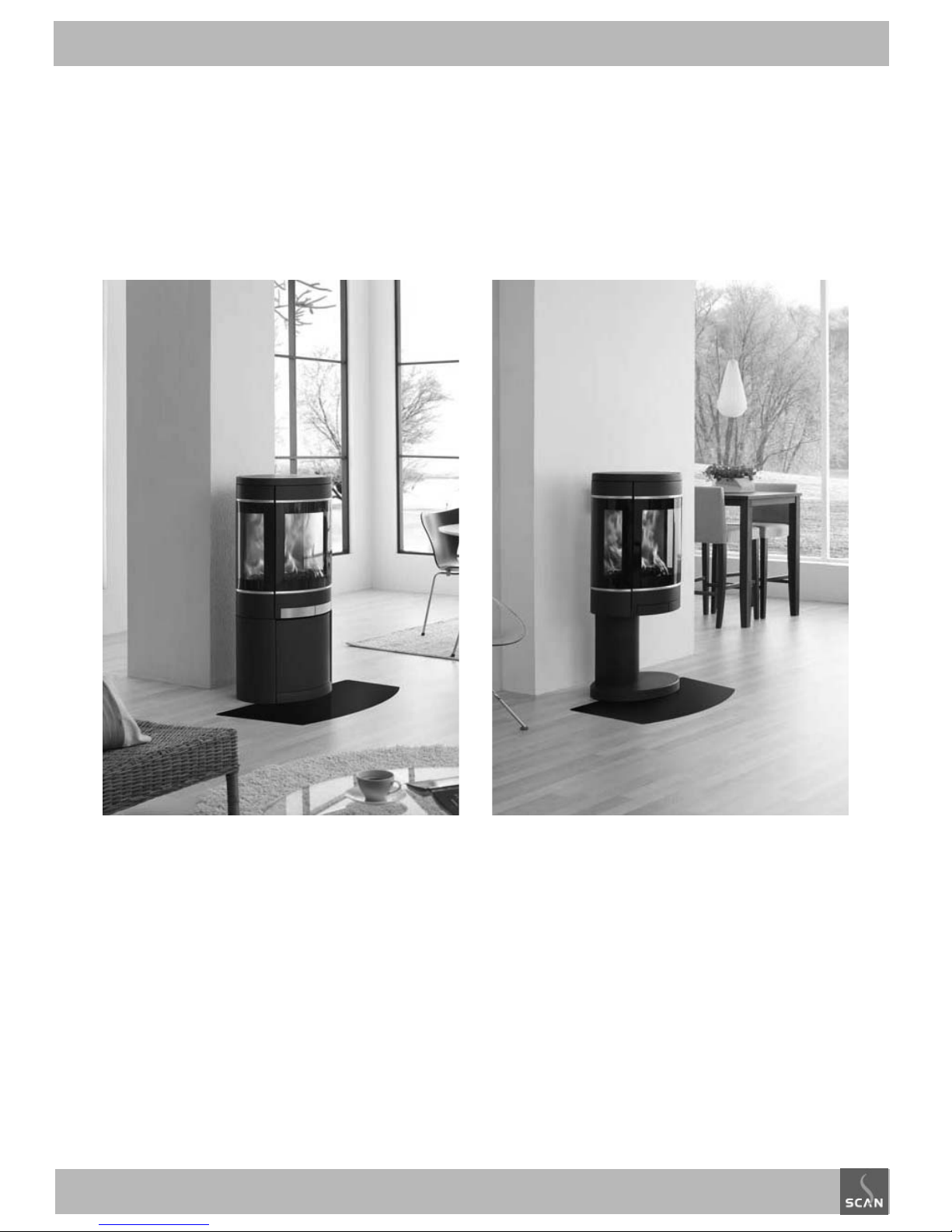
Scan 58 - series
ASSEMBLY- AND INSTRUCTIONS MANUAL
Congratulations on your new Scan wood-burning stove
You have purchased a product by one of Europe’s leading manufacturer’s of wood-burning stoves, and we are sure that you will have years of plea-
sure with your purchase. To make the best possible use of your stove, it is important that you follow our advice and instructions.
Please read this Assembly- and instructions manual before you start to assemble your stove.
Page 2

2
CONTENTS
Table of contents
Technical data .............................................................................................. 3
Installation
Safety
Technical data and dimensions
Dimension sketch for Scan 58 - series
Type plate
Assembly ...................................................................................................... 10
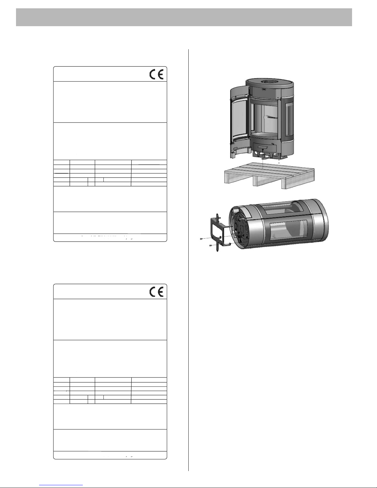
Transport brackets
Service box
Additional accessories
Positioning your wood-burning stove
Positioning near to non-flammable materials
Distance to furniture
Diatance to fl ammable walls
Product registration number
Adjusting screws
Load bearing foundation
Floor plate
Existing chimney and pre-fabricated element chimney
Connection between stove and steel chimney
Requirements for chimney
Connection with 90° elbow pipe
Fitting the stove onto the plinth
Fresh air intake
Closed combustion system
Connecting piece top outlet
Preparing the stove for rear outlet
Wall-hung model
Fitting the Scan 58 wall-hung model
Scan 58-9 and Scan 58-10
Scan 58-9 and Scan 58-10 with high top
Accessories .................................................................................................. 20
Mounting of high top for Scan 58-7 and Scan 58-8
Wall mounting kit for Scan 58 with high top
Heat accumulating stones for high top
Fitting the soapstone top
Fitting a storage door
Instruction for use ................................................................................... 26
CB technique
Primary air
Secondary air
Baffl e plates
Ash drawer
Handle for riddling grate
Instructions for heating ......................................................................... 27
Lighting
Handling fuel
Maintenance .............................................................................................. 29
Troubleshooting ........................................................................................ 31
Page 3
TECHNICAL DATA
3
Installation
The house owner is responsible for ensuring that all necessary national and local safety measures are observed during installation and
fitting and also responsible for observing the fitting and operating
instructions detailed in this manual.
When you install any kind of fireplace or stove, you must inform the
local authorities. You are also responsible for calling in a chimney
sweep to inspect and authorize the installation.
To ensure best-possible functionality and safety for your installation,
we advise you to call a professional fitter. Our Scan Dealer will be able
to recommend a qualified fitter in your area. For information on Scan
Dealers, please go to www.scan.dk.
Safety
Any changes made to the product by the dealer, installer or user
could result in the product and safety functions not functioning
as intended. The same applies to the fitting of accessories or extra
equipment not supplied by Scan A/S. This could also be the case if
parts that are necessary for the operation and safety of the stove are
dismantled or removed.
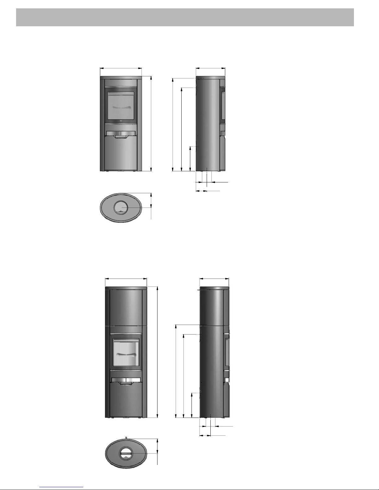
Technical data and dimensions
Materials: steel plate, cast iron, galvanised sheet, skamol
Surface treatment: Senotherm
Max. wood length: 33 cm
Weight Scan 58: ca. 100 kg
Weight Scan 58-9 and Scan 58-10: ca. 160 kg
Weight Scan 58-7 and Scan 58-8 with high top: ca. 120 kg
Weight Scan 58-9 and Scan 58-10 with high top: ca. 200 kg
Weight heat-accumulating stones: ca. 86,5 kg
Connecting piece internal diameter: 135 mm
Connecting piece external diameter: 148 mm
Approval type: Intermittent fuelling
Test in compliance with EN 13240
Basic data for the Scan 58 - series
CO Emission at 13% O2: 0,11% 1338 mg/Nm
3
Dust @ 13% O2: 44 mg/Nm
3
Nox @ 13% O2: 119 mg/Nm3
Nominel output: 5,5 kW
Amount of smoke: 6 g/sek
Sub-pressure EN 13240: 12 Pa
Recommended sub-pressure in connecting piece: 18-20 Pa
Required combustion air supply: 16,5 Nm3/h
Fuel: Wood
Fuel consumption: 1,8 kg/h
Amount of fuel: 1,4 kg
Scan 58 excl. high top
Efficiency: 76%
Chimney temperature EN 13240: 271 °C
Temperature in connecting piece: 350 °C
Scan 58 incl. high top
Efficiency: 80%
Chimney temperature EN 13240: 228 °C
Temperature in connecting piece: 300 °C
Intermittent fuelling means normal use of a woodstove. In other
words, you should let the fire die down until only the embers are left,
before refuelling.
The Scan 58-series was build in compliance with the homologized
product type specified in the Assembly- and Instructions Manual
provided with the product.
The EC declaration of conformity is available from www.scan.dk
Page 4
TECHNICAL DATA
1
1
3
8
1
7
5
9
9
8
*
175***
1
1
1
2
*
*
350500
108Ø
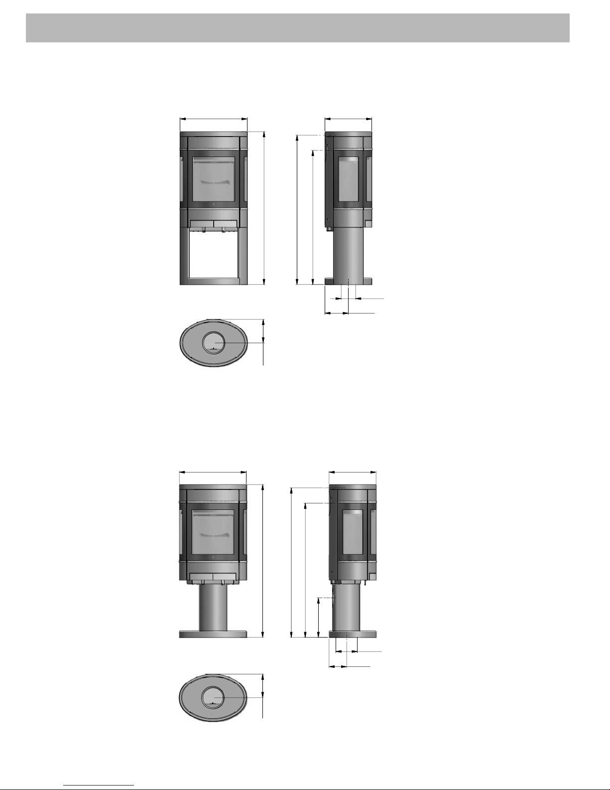
Dimension sketch Scan 58 with "see through" plinth
* Centre rear outlet
** Height to the beginning
of the connecting piece
at top outlet
*** Centre of fresh air in take bottom
**** Centre of fresh air intake
rear
* Height to the begin ning of the connecting
piece at top outlet
** Centre of fresh air in take bottom
*** Centre of fresh air in take rear
Dimension sketch Scan 58 with pedestal plinth
1
1
3
8
500
1
7
5
350
1
1
1
2
*
*
2
9
4
*
*
*
*
131***
160Ø
9
9
8
*
4
Page 5
TECHNICAL DATA
5
500 350
403
7
6
4
6
2
4
*
5
7
2
*
7
3
6
*
*
6
8
4
*
*
4
3
0
*
*
*
*
2
2
8
184***
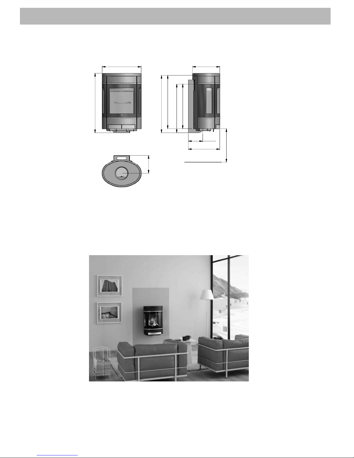
Dimension sketch Scan 58 Wall-hung model
* Centre rear outlet
** Height to the beginning
of the flue pipe at top
outlet
*** Centre of fresh air in take bottom
**** Minimum clearance
above flammable mate
rial
Page 6
500 350
1
5
7
2
2
9
6
*
*
*
131***
114Ø
1
1
1
4
*
*
1
7
5
1
0
0
0
*
TECHNICAL DATA
6
500 350
1
1
4
0
1
1
1
4
*
*
2
9
6
*
*
*
*
1
0
0
0
*
1
7
5
114Ø
131***
Dimension sketch Scan 58-7 and Scan 58-8
* Centre rear outlet
** Height to the beginning
of the connecting piece
at top outlet
*** Centre of fresh air in take bottom
**** Centre of fresh air intake
rear
* Height to the begin ning of the connecting
piece at top outlet
** Centre of fresh air in take bottom
*** Centre of fresh air in take rear
Dimension sketch Scan 58-7 and Scan 58-8 with high top
Page 7
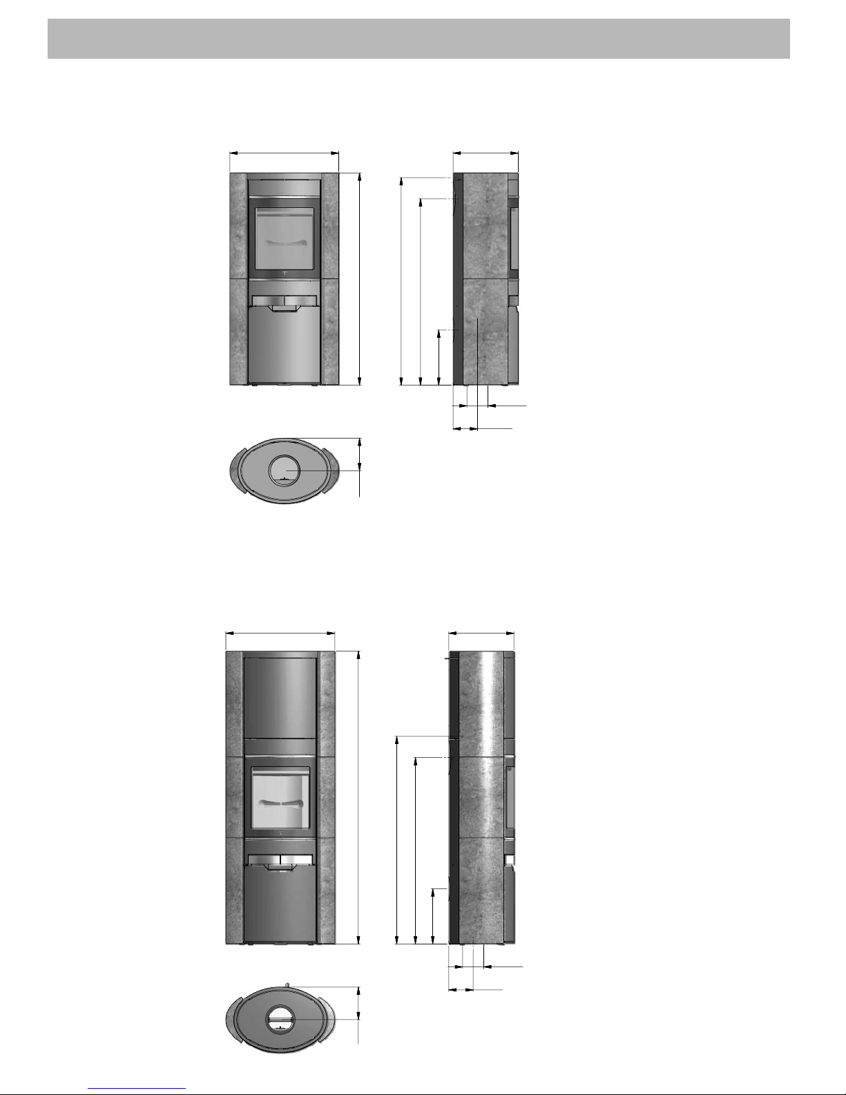
TECHNICAL DATA
7
350
1
7
5
1
1
1
4
*
2
9
6
*
*
*
114Ø
131**
1
5
7
2
1
0
0
0
586
* Height to the begin ning of the connecting
piece at top outlet
** Centre of fresh air in take bottom
*** Centre of fresh air in take rear
Dimension sketch Scan 58-9 and Scan 58-10 with high top
1
1
4
0
586 350
2
9
6
*
*
*
*
1
0
0
0
*
114Ø
131***
1
7
5
1
1
1
4
*
*
Dimension sketch Scan 58-9 and Scan 58-10
* Centre rear outlet
** Height to the beginning
of the connecting piece
at top outlet
*** Centre of fresh air in take bottom
**** Centre of fresh air intake
rear
Page 8
TECHNICAL DATA
8
Scan 58-3 & Scan 58-6 (with full lateral glass panes)
Scan 58-3 + Scan 58-
6
Freestanding room heater fired by solid fue
l
Standar
d:
Fuel type:
Operation type:
The appliance can be operated in a shared flue.
C
ountry
E
N 13240 EC no. 90
358602
Wood
Intermittent
EU
R
Norway
y
Classification
Intermittent
Klasse
2
C
ertificate/Standard
EN 13
240
SINTEF 110-029
8
Approved
by
pp y
RWE Power A
G
S
INTEF - NBL
Dust CO emission at 13% O2: 44 mg/Nm³
Flue gas temperature: 350°C
Nominal heat output: 5,5
kW
Efficiency: 76%
Scan A/S DK 5492 Vissenbjerg
M
inimum distance to combustible materials
:
Sid
e: 600 mm - Back: 250 mm - Front: 1000 mm
C
O emission at 13% O2:
Follow assem
bly
- and instructions manua
l.
Use only recommended fuels
.
Montage- und Bedienungsanleitung beachten
.
Verwenden Sie nur empfohlene Brennstoffe
.
1000 05-2009
S
can
A/S DK
5492 Vissenbjer
g
0,11% 1338 mg/Nm
³
Schwei
z
Germany
y
LRV 1
1
BStV 1
VKF N 18900
F
SPS-Wa 1769-E
N
RWE Power A
G
RWE Power A
G
Type plates
All Scan wood-burning stoves are fitted with a type plate, that specifies the approval standards and the distance to flammable materials.
The type plate on the Scan 58-7, Scan 58-8, Scan 58-9 and Scan 58-10 is located in the magazine under the combustion chamber.
Scan 58-1 & Scan 58-4 (without lateral glass panes)
Scan 58-1 + Scan 58-4
Freestanding room heater fired by solid fuel
Standar
d:
Fuel type:
Operation type
:
The appliance can be operated in a shared flue
.
Countr
y
E
N 13240 EC no. 90
358600
Woo
d
Intermitten
t
E
UR
Norway
y
Classificatio
n
Intermitten
t
Klasse 2
Certificate/Standar
d
EN
1324
0
SINTEF 110-02
98
App
roved
by
pp y
RWE Power A
G
S
INTEF - NBL
Dust CO emission at 13% O2: 44 mg/Nm
³
Flue gas temperature: 350°C
Nominal heat output: 5,5
kW
Efficiency: 76%
Scan A/S DK 5492 Vissenbjerg
M
inimum distance to combustible materials
:
Sid
e: 350 mm - Back: 250 mm - Front: 1000 m
m
CO emission at 13% O2
:
Follow assem
bly
- and instructions manua
l.
Use only recommended fuels
.
Montage- und Bedienungsanleitung beachten.
Verwenden Sie nur empfohlene Brennstoffe.
1000 05-2009
S
can
A/S DK
5492 Vissenbjer
g
0
,11% 1338 mg/Nm³
Schwei
z
Germany
y
LRV 11
BStV 1
VKF N 18900
FSPS-Wa 1769-E
N
RWE Power A
G
RWE Power A
G
Scan 58-2 & Scan 58-5 (with half lateral glass panes)
Scan 58-2 + Scan 58-
5
Freestanding room heater fired by solid fuel
Standar
d:
Fuel type:
Operation type
:
The appliance can be operated in a shared flue
.
Countr
y
E
N 13240 EC no. 90
358601
W
ood
Intermitten
t
E
UR
Norway
y
Classificatio
n
Intermitten
t
Klasse 2
Certificate/Standar
d
EN 1324
0
SINTEF 110-029
8
App
roved
by
pp y
RWE Power A
G
S
INTEF - NBL
Dust CO emission at 13% O2: 44 mg/Nm
³
Flue gas temperature: 350°C
Nominal heat output: 5,5
kW
Efficiency: 76%
Scan A/S DK 5492 Vissenbjerg
M
inimum distance to com
bustible materials:
Sid
e: 600 mm - Back: 250 mm - Front: 1000 m
m
CO emission at 13% O2
:
Follow assem
bly
- and instructions manua
l.
Use only recommended fuels
.
Montage- und Bedienungsanleitung beachten.
Verwenden Sie nur empfohlene Brennstoffe.
1000 05-2009
S
can
A/S DK
5492 Vissenbjer
g
0
,11% 1338 mg/Nm³
Schwei
z
Germany
y
LRV 11
BStV 1
VKF N 18900
FSPS-Wa 1769-E
N
RWE Power A
G
RWE Power A
G
Scan 58-1 Wall & Scan 58-4 Wall (without lateral glass panes)
Scan 58-1 Wall + Scan 58-4 Wa
ll
Wall mounted room heater fired by solid fue
l
Standar
d:
Fuel type:
Operation type:
The appliance can be operated in a shared flue.
C
ountr
y
E
N 13240 EC no. 90
358611
Wood
Intermittent
E
UR
Norway
y
Classification
Intermittent
Klasse
2
C
ertificate/Standard
EN 13240
SINTEF 110-029
8
Approved
by
pp y
RWE Power A
G
S
INTEF - NBL
Dust CO emission at 13% O2: 44 mg/Nm³
Flue gas temperature: 350°C
Nominal heat output: 5,5
kW
Efficiency: 76%
Scan A/S DK 5492 Vissenbjerg
M
inimum distance to com
bustible materials:
Sid
e: 350 mm - Front: 1000 m
m
C
O emission at 13% O2:
Follow assem
bly
- and instructions manua
l.
Use only recommended fuels
.
Montage- und Bedienungsanleitung beachten
.
Verwenden Sie nur empfohlene Brennstoffe
.
1000 05-2009
S
can
A/S DK
5492 Vissenbjer
g
0,11% 1338 mg/Nm
³
Schwei
z
Germany
y
LRV 1
1
BStV 1
VKF N 18900
F
SPS-Wa 1769-E
N
RWE Power A
G
RWE Power A
G
Page 9
TECHNICAL DATA
9
Scan 58-2 Wall & Scan 58-5 Wall (with half lateral glass panes)
Scan 58-2 Wall + Scan 58-5 Wa
ll
Wall mounted room heater fired by solid fuel
Standar
d:
Fuel type
:
Operation type
:
The appliance can be operated in a shared flue
.
Countr
y
E
N 13240 EC no. 90
358612
Woo
d
Intermitten
t
E
UR
Norway
y
C
lassificatio
n
Intermitten
t
Klasse 2
C
ertificate/Standar
d
EN
1324
0
SINTEF 110-02
98
App
roved
by
pp y
RWE Power A
G
S
INTEF - NBL
Dust CO emission at 13% O2: 44 mg/Nm
³
Flue gas temperature: 350°
C
Nominal heat output: 5,5
kW
Efficiency: 76%
Scan A/S DK 5492 Vissenbjerg
M
inimum distance to combustible materials
:
Side:
600
mm - Front: 1
000 mm
C
O emission at 13% O2
:
Follow assem
bly
- and instructions manua
l.
Use only recommended fuels
.
Montage- und Bedienungsanleitung beachten.
Verwenden Sie nur empfohlene Brennstoffe.
1000 05-2009
S
can
A/S DK
5492 Vissenbjer
g
0,11% 1338 mg/Nm
³
Sch
wei
z
Germany
y
LRV 11
BStV 1
VKF N 18900
FSPS-Wa 1769-E
N
RWE Power A
G
RWE Power A
G
Scan 58-3 Wall & Scan 58-6 Wall (with full lateral glass panes)
Scan 58-3 Wall + Scan 58-6 Wa
ll
Wall mounted room heater fired by solid fuel
Standard:
Fuel type
:
Operation type
:
The appliance can be operated in a shared flue
.
Countr
y
E
N 13240 EC no. 90
358613
Woo
d
Intermitten
t
E
UR
Norway
y
C
lassificatio
n
Intermitten
t
Klasse 2
C
ertificate/Standar
d
EN 1324
0
SINTEF 110-029
8
App
roved
by
pp y
RWE Power A
G
S
INTEF - NBL
Dust CO emission at 13% O2: 44 mg/Nm
³
Flue gas temperature: 350°
C
Nominal heat output: 5,5
kW
Efficiency: 76%
Scan A/S DK 5492 Vissenbjerg
M
inimum distance to combustible materials
:
Side:
600
mm - Front: 1
000 mm
C
O emission at 13% O2
:
Follow assem
bly
- and instructions manua
l.
Use only recommended fuels
.
Montage- und Bedienungsanleitung beachten.
Verwenden Sie nur empfohlene Brennstoffe.
1000 10-2009
S
can
A/S DK
5492 Vissenbjer
g
0,11% 1338 mg/Nm
³
Sch
wei
z
Germany
y
LRV 11
BStV 1
VKF N 18900
FSPS-Wa 1769-E
N
RWE Power A
G
RWE Power A
G
Scan 58-7 & Scan 58-8
Scan 58-7 + Scan 58-8
Freestanding room heater fired by solid fue
l
Standar
d:
Fuel type:
Operation type:
The appliance can be operated in a shared flue.
C
ountr
y
E
N 13240 EC no. 9035860
9
Wood
Intermittent
EU
R
Norway
y
Classification
Intermittent
Klasse
2
C
ertificate/Standard
EN 13
240
SINTEF 110-02
98
Approved
by
pp y
RWE Power A
G
S
INTEF - NBL
Dust CO emission at 13% O2: 44 mg/Nm³
Flue gas temperature: 350°C
Nominal heat output: 5,5
kW
Efficiency:76
%
Scan A/S DK 5492 Vissenbjerg
M
inimum distance to combustible materials
:
Sid
e: 350 mm - Back: 250 mm - Front: 1000 mm
C
O emission at 13% O2:
Follow assem
bly
- and instructions manua
l.
Use only recommended fuels
.
Montage- und Bedienungsanleitung beachten
.
Verwenden Sie nur empfohlene Brennstoffe
.
1000 05-2009
S
can
A/S DK
5492 Vissenbjer
g
0,11% 1338 mg/Nm
³
Schwei
z
Germany
y
LRV 1
1
BStV 1
VKF N 18900
FSPS-Wa 1769-E
N
RWE Power A
G
RWE Power A
G
Scan 58-7 & Scan 58-8 with high top
S
can 58-7 + Scan 58-8 with high to
p
Freestanding room heater fired by solid fue
l
Standard:
Fuel type
:
Operation type:
The appliance can be operated in a shared flue.
y
C
ountr
y
EN 13240 EC no. 90
358
619
Woo
d
Intermitten
t
E
UR
Norway
y
Austri
aClass
ificati
on
Intermitten
t
K
lasse 2
Certificate/Standar
d
EN
13240
SINTEF 110-0298
15
a B-VG
Approved
by
pp y
RWE Power A
G
S
INTEF - NB
L
RWE Power A
G
Dust at 13% O2: 44 mg/Nm
³
Flue gas temperature: 300
°C
Nominal heat output: 5,5
kW
Efficiency: 80%
Angaben für Österreic
h
W
ärmeleistungsbereich: 3,0 - 6,7 kW
Brennstoffwärmeleistung: 8,4 k
W
Zulässige Brennstoffe: Scheitholz
Prüfbericht
:
FSPS-Wa 1769-A
Scan A/S DK 5492 Vissenbjerg
Minimum distance to com
bustible materials:
Side: 350 mm - Back: 250 mm - Front: 1000 m
m
C
O emission at 13% O2
:
Follow assembly- and instructions manua
l.
Use only recommended fuels.
Montage- und Bedienungsanleitung beachten
.
V
erwenden Sie nur empfohlene Brennstoffe
.
1000 06-2010
Scan A/S DK
549
2 Vissenbjer
g
0
,11% 1338 mg/Nm
³
Schweiz
G
erman
y
y
LRV 11
BStV 1
VKF N 18900
FSPS-Wa 1769-E
N
RWE Power A
G
RWE Power A
G
Page 10
ASSEMBLY
10
Additional accessories
• Large shaped floor plate in glass or steel.
• Small shaped floor plate in steel
• Soap stone top for rear outlet
• Soap stone top for top outlet
• Soap stone top for stove with soap stone sides
• Soap stone top with hole for stove with soap stone sides
• Glass top plate for rear outlet
• Glass top plate for top outlet
• Storage door
• High top (Scan 58-7 and Scan 58-8)
• Wall mounting kit for Scan 58 with high top
Transport brackets
For Scan 58 with pedestal and see-through base / Scan 58 wall model,
remove the transport brackets as shown below.
Service box
The service box contains the following:
• Fitting for connecting piece
• Seal
• Safety fitting
• Plastic plugs for transport safety hole at the bottom of
the stove (not used for this Scan model)
• Various tools
• Glove
• Fire starters for first lighting
Scan 58-9 & Scan 58-10
Scan 58-9 + Scan 58-1
0
Freestanding room heater fired by solid fue
l
Standar
d:
Fuel type
:
Operation type
:
The appliance can be operated in a shared flue.
y
C
ountr
y
E
N 13240 EC no. 90
358617
Wood
Intermitten
t
EUR
Norway
y
Class
ificati
on
Intermittent
K
lasse 2
C
ertificate/Standar
d
EN 13
240
SINTEF 110-029
8
Approved
by
pp y
RWE Power A
G
S
INTEF - NBL
Dust at 13% O2: 44 mg/Nm
³
Flue gas temperature: 350
°C
Nominal heat output: 5,5
kW
Efficiency: 76%
Scan A/S DK 5492 Vissenbjerg
Minimum distance to com
bustible materials:
Side: 350 mm - Back: 250 mm - Front: 1000 m
m
CO emission at 13% O2
:
Follow assembly- and instructions manua
l.
Use only recommended fuels
.
Montage- und Bedienungsanleitung beachten.
V
erwenden Sie nur empfohlene Brennstoffe
.
1000 06-2010
Scan A/S DK
549
2 Vissenbjer
g
0,11% 1338 mg/Nm
³
Schweiz
G
erman
y
y
LRV 1
1
BStV 1
VKF N 18900
FSPS-Wa 1769-EN
RWE Power A
G
RWE Power A
G
Scan 58-9 & Scan 58-10 with high top
Scan 58-9 + Scan 58-10 with high to
p
Freestanding room heater fired by solid fue
l
Standard:
Fuel type
:
Operation type
:
The appliance can be operated in a shared flue.
y
C
ountr
y
E
N 13240 EC no. 90
358620
Wood
Intermitten
t
EUR
Norway
y
Austri
a
Class
ificati
on
Intermittent
K
lasse 2
C
ertificate/Standar
d
EN
13240
SINTEF 110-02
98
15 a B-V
G
Approved
by
pp y
RWE Power A
G
S
INTEF - NBL
RWE Power A
G
Dust at 13% O2: 44 mg/Nm³
Flue gas temperature: 300°C
Nominal heat output: 5,5
kW
Efficiency: 80
%
Ang
aben für Österreic
h
Wärmeleistungsbereich: 3,0 - 6,7
kW
Brennstoffwärmeleistung: 8,4 k
W
Zulässige Brennstoffe: Scheithol
z
Prüfbericht:
F
SPS-Wa 1769-A
Scan A/S DK 5492 Vissenbjerg
Minimum distance to com
bustible materials:
Side: 350 mm - Back: 250 mm - Front: 1000 m
m
CO emission at 13% O2
:
Follow assem
bly
- and instructions manua
l.
Use only recommended fuels
.
Montage- und Bedienungsanleitung beachten.
V
erwenden Sie nur empfohlene Brennstoffe
.
1000 06-2010
Scan A/S DK
549
2 Vissenbjer
g
0,11% 1338 mg/Nm
³
Schweiz
G
erman
y
y
LRV 1
1
BStV 1
VKF N 18900
FSPS-Wa 1769-EN
RWE Power A
G
RWE Power A
G
Page 11
ASSEMBLY
11
Distance to flammable walls
2
5
0
600
45° Corner installation
Parallel rear wall installation
Positioning your wood-burning stove
The wood-burning stove must be set up so that the stove itself, the flue pipe, and the chimney can all be cleaned.
Position near to non-flammable walls
When positioning near a non-flammable wall, we recommend you keep a minimum distance of 50 mm between the rear of the product and the
wall for cleaning purposes.
Distance to furniture: 1000 mm
But please check to avoid furniture or other furnishings being dried out due to being too close to the stove.
2
5
0
600
2
5
0
350
Scan 58-3 & Scan 58-6 (with full lateral glass panes)
Parallel rear wall installation
Scan 58-2 & Scan 58-5 (with half lateral glass panes)
45° Corner installation
Scan 58-1 & Scan 58-4 (without lateral glass panes)
Scan 58-7, Scan 58-8, Scan 58-9, Scan 58-10 og Scan 58 with high top
Parallel rear wall installation
45° Corner installation
4
0
0
400
70
1
2
5
0
250
48
6
2
0
0
200
4
1
5
Page 12

12 ASSEMBLY
600
350
Scan 58-2 Wall & Scan 58-5 Wall (with half lateral glass panes)
Scan 58-3 Wall & Scan 58-6 Wall (with full lateral glass panes)
Scan 58-1 Wall & Scan 58-4 Wall (without lateral glass panes)
Non-flammable wall
Flammable wall
Non-flammable wall
Flammable wall
Product registration number
Adjusting screws
Adjusting screws
The Scan 58 has four adjusting screws under the plinth of the woodburning stove. Use the adjusting screws to get the stove to stand
vertically.
Tilt the plinth and adjust the screws before fitting the stove in place.
On the Scan 58-7, Scan 58-8, Scan 58-9 and Scan 58-10 you can also
choose to adjust the adjustment screws in the magazine under the
combustion chamber.
If you are using a shaped floor plate, you should adjust the stove
upwards to allow the plate to be inserted under the front of the stove.
Adjusting screws
Product registration number
Open the door and read the product registration number. Make a
note of the number below. This number must be kept safe, in case
you need to contact us.
Page 13

ASSEMBLY
13
Load bearing underlay
All of the products in our portfolio are classified as light-duty fireplaces; in most cases, there is no need to reinforce the floor, so that you
can typically use the normal floor.
However, you should make sure that the load bearing underlay can
bear the weight of the wood-burning stove and that of the chimney.
Floor plate
If you are setting up the stove on a flammable floor, observe national
and local regulations on the size of the non-flammable underlay that
covers the floor around the stove.
Your local Scan dealer can advise you on regulations concerning
flammable materials in the vicinity of your stove.
The idea behind the floor plate is that it protects the floor and flammable material against sparks.
The floor plate can be made of steel or glass, and the stove can be set
up on brick, natural stone or similar materials.
This Scan wood-burning stove has an integrated floor plate, and
can thus be set up on any flammable material without a protective
underlay.
If you have chosen the Scan 58 wall-hung model, the floor plate must
extend right back to the hanging wall.
Small shaped floor plate for the Scan 58
Large shaped floor plate for the Scan 58
Existing chimney and pre-fabricated element
chimney
If you intend to connect your stove to an existing chimney, it makes
sense to contact an authorised Scan dealer, or a local chimney sweep
for advice. These experts will also let you know if your flue needs
renovating.
When connecting a pre-fabricated element chimney, follow the
manufacturer’s connection instructions for the relevant chimney
type.
Connection between stove and steel chimney
Your Scan dealer, or local chimney sweep, can advise you on choosing
a make and type of steel chimney. This ensures that the chimney
will match your wood-burning stove. As a general rule, the length of
the flue should not be less than 3,5 m measured from the top of the
wood-burning stove.
Choosing the wrong length or diameter of steel chimney could
impair functionality.
Always observe the chimney vendor‘s instructions precisely.
Requirements for chimney
The chimney must be labelled T400 and G for soot testing.
Connection with 90° elbow pipe
If you intend to use an elbow pipe with the Scan 58, we recommend
the use of a curved elbow pipe to improve the draft.
If you are connecting your stove using a sharp elbow bend, the cleanout door should be in the vertical section, such that the horizontal
part can be cleaned through it.
Scan 58 with high top can be fi tted with an elbow pipe provided that
the stove is fi xed to the wall using a special wall mounting kit. This
kit can be purchased from your local Scan dealer.
Page 14

14 ASSEMBLY
4 x allen screws M6x70
A
A
Fitting the stove onto the plinth
There are two plinths for the Scan 58. You can see how to fit these
below. Use the key supplied with the service pack to make the attachment secure.
A
Scan 58 with pedestal plinth
If you have decided to connect external combustion air via the pedestal plinth, mount the connection piece supplied before fitting the
plinth to the stove.
Scan 58 with "see through" plinth
Fresh air intake
In a well-insulated house, the air used up by the burning process
has to be replaced. This particularly applies to houses with mechanical ventilation. There are different ways of making sure that an air
exchange takes place. The most important thing is to ensure that
there is a supply of air to the room where the wood stove is located.
The external wall vent must be located as close to the wood stove as
possible, and you must be able to close it when you are not using the
wood stove.
National and local building regulations must be followed with
regard to the connection of fresh-air intake.
Closed combustion system
If you have decided to use the stove’s closed combustion system, connect the external combustion air using a ventilation pipe passing
through the wall or floor.
It must not be possible to shut off the ventilation pipe with a valve
• Minimum Ø100 mm ventilation pipe, maximum length: 6 m
with a maximum of one bend
The Scan 58 with pedestal plinth
External combustion air can be connected via the pedestal or plinth
base by fitting the connection piece supplied to the pedestal plinth
and connecting outdoor air.
External combustion air via wall
External combustion air via floor
Page 15

ASSEMBLY
15
Connecting piece top outlet
Your wood-burning stove has been prepared for a top outlet by the
manufacturer. Remove the cover plate from the top plate, and fit the
connecting piece, the enclosed seal, and the fittings from the service
package. At the same time, fix the safety fitting crosswise to prevent
damage to the baffle plate when sweeping the chimney.
Connecting
piece
Safety
fitting
B
B
Bracket
Seal for
connecting
piece
Screws for
adjusting
the height
of the top
plate
Screws for adjusting the height
of the frame for
the top plate
The Scan 58 with "see through" plinth
External combustion air can be connected underneath the combustion chamber using the connection piece supplied and connecting
outdoor air.
If you decide on connecting external combustion air through the
bottom of the plinth, unscrew the blanking plate and fit it under the
combustion chamber. Then fit the connection piece supplied under
the plinth as shown below before connecting outdoor air.
Scan 58-7 and Scan 58-8
External combustion air can be connected in the magazine under the
combustion chamber by fitting the connection piece and fresh air
box supplied. Outdoor air can then be connected through the bottom
or rear of the stove.
Scan 58 Wall-hung model
Page 16

16 ASSEMBLY
Preparing the stove for rear outlet
Remove the top plate and the frame for the top plate. The Allen
screws and discs are to be reused, when the stove is assembled again.
To attach the flue pipe, remove the cover plate on the rear plate
and heat shield as follows:
Drill out the four holes in the cover plates with a Ø8 bit and
remove the plates.
4 allen screws M6x10
C
C
Loosen the cast iron cooking plate from the inside and remove.
This is to be used later as a seal and cover at the top of the smoke
outlet.
Fit the separate connecting piece in place from the outside and fix in
place using the bracket and seal supplied in the service pack. Fit the
frame for the top plate.
C
Connecting
piece
Seal for con-
necting piece
Use pliers to cut the anchor points on the heat shield and
remove the shield.
Anchor points
4 discs Ø 6.5 / Ø16 x 1.1
Page 17

ASSEMBLY 17
D
D
Fit the cast iron cooking plate in the smoke outlet. Place the top plate
on the stove.
Bracket
Allen screw
Wall-hung model
Installation must be planned and executed in accordance with natio-
nal and local building regulations.
The stove must only be fitted to a non-flammable wall. There must
be no form of flammable component in the wall. In the case of thin
walls, nor must there be any behind the wall. The load-bearing capa-
city of the wall must be checked under all circumstances.
To ensure correct installation we recommend that a building expert
be commissioned to plan and outline the installation with a view to
subsequent approval.
For wall installation we recommend using the wall brackets supplied.
If a chimney is installed on top of a wall-hung model, the chimney
must be fully self-supporting. It must not rest on the wood-burning
stove. There must be a distance of at least 6 mm between the first
section and the flange on the flue collar (see below). Please consult
a specialist.
Scan A/S disclaims all liability for the installation of wall-hung
wood-burning stoves.
Fitting the Scan 58 wall-hung model
Remove the screws in the rear casing of the stove.
Remove the type plate from the stove and replace it with the type
plate corresponding to the wall model in question. The type plate for
the wall model is packed together with the wall fitting.
First section
Flange on
the connecting
piece
Screws for
adjusting
the height
of the top
plate
Screws for adjusting the height
of the frame for
the top plate
Page 18

ASSEMBLY
18
Fit the wall brackets to the wall. Fit the washers and screws for the rear casing (E). Fasten these only once fitting of the stove is complete.
Hang the stove on the wall bracket. The pegs in the wall bracket must ‘catch’ in the holes at the bottom of the stove (F). Fit and tighten the screws
for the wall bracket and stove (G).
Fitting of the stove is now complete. Tighten the screws and washers in the rear casing (E).
2 x allen screws M5x30
2 x washers
6 allen screws M6x70
E
E
G
G
F
Nose on wall
bracket
F
0
2040668
6
1
0
6
1
3
2
1
5
2
1
7
2
0
33
67
100
268
301
335
368
9
8
,
5
Page 19

ASSEMBLY
19
8 distance bushings for soap stone
8 screws 6 x 30 mm for soap stone
Each soap stone is to be mounted with distance bushings and screws
(pos. H). These are delivered together with the stove. Use a Torx
screwdriver for tightening the screws. You are not to use any electrical tools, as this might tighten the screws too much, resulting in the
soap stones breaking.
Mount the soap stone sides on the stove.
H
H
Scan 58-9 and Scan 58-10
Scan 58-9 and Scan 58-10 are delivered with loose soap stone plates
for mounting on the sides of the stove.
Soap stone is a natural material, wherefore there might be differences in structure and form.
The delivered gasket should be cut in pieces of 1 meter and sticked
onto the sides of the stove, on the outer side of the markings as
shown below.
Gasket
Marking
Page 20

ACCESSORIES
20
12 distance bushings for soap stone
12 screws 6 x 30 mm for soap stone
The high top and the chimney are mounted as described in the section ”Mounting of high top for Scan 58-7 and Scan 58-8 on page 21”.
I
I
Scan 58-9 and Scan 58-10 with high top
4 gaskets each 35 cm
In order to prepare the stove for mounting of soap stones, we refer
to the section ”Scan 58-9 and Scan 58-10”, page 19. However, the soap
stones must be mounted according to the size as shown below (the
smaller stone in the middle).
The delivered gasket should be cut in pieces of 35 cm and sticked onto
the high top of the stove, on the outer side of the markings as shown
below.
Each soap stone must be mounted with distance bushings and
screws (pos. I). These are delivered with the soap stone and the high
top.
Page 21

ACCESSORIES
21
4 x allen screws M6x10
4 discs Ø 6.5 / Ø16 x 1.1
L
Remove the top plate and the frame for the top plate. The Allen
screws and discs (pos. L) are to be reused when the high top is fastened on the stove.
When remounting the frame for the top plate, it should be turned
180°, so that the heat shield turns towards the front of the door of
the stove.
L
Heat shield
Mounting of high top for Scan 58-7 and Scan 58-8
2 x allen screws M5x25
K
K
J
J
Loosen the screws in the bottom
of the high top.
If you choose to connect the stove with an elbow pipe or a rear outlet, the stove must be mounted to the wall behind the oven using a
special wall mounting kit. This kit can be purchased from your local
Scan dealer. For fitting, see page 24.
It is very important that the base is level and stable.
The type plate delivered with the high top is to replace the type plate
placed on the stove. Remove the existing type plate from the stove
and replace it with the new one. The type plate is to be found in the
compartment under the burn chamber.
Mounting of the high top:
The front plate of the high top is removed as follows:
Loosen the screws (pos. J). Remove the Allen screws (pos. K). Remove
the front of the high top.
Page 22

ACCESSORIES
22
Place the top plate and the frame for the top plate on the stove without fastening them. Mount the chimney.
L
For mounting of the flue collar, see page 15: “Connecting piece top
outlet”.
Mount the high top, adjust the height and tighten it.
Screws
for height
adjustment
of the high
top
Page 23

ACCESSORIES
23
4 x allen screws M6510
4 discs Ø 6.5 / Ø16 x 1.1
Fasten the frame for the top plate (the heat shield must turn towards
the door) with the screws and discs (pos. M) delivered with the high
top.
Remount the front plate for the high top and tighten it.
Tighten the
screws in the bottom of the front
plate.
Screws for
adjusting
the height
of the top
plate
Screws for
adjusting the
height of the
frame for the
top plate
M
M
Heat shield
Page 24

ACCESSORIES
24
Wall mounting kit for Scan 58 with high top
If you choose to connect the stove with an elbow pipe or a rear outlet, the stove must be mounted to the wall behind the oven using a
special wall mounting kit. This kit can be purchased from your local
Scan dealer
See page 21 for how to fit the high top.
Fit the wall mounting kit before connecting the stove to the chimney.
It is important that the stove is mounted securely to the wall
using the right fixings for the specific type of wall.
Safety wire
Casing for wire bushing
Fix to the wall using the
right fixings for the specific type of wall.
Wire bushing
Pointed screw M4x5
Nipple screw Ø8x12.5
Scan 58 high top with elbow pipe
N:
Casing for wire bushing is fixed to the wall
Fasten the safety wire and the wire bushing to the wire bushing
casing using a pointed screw.
N
N
Page 25

ACCESSORIES
25
O
O
O:
Fasten the safety wire to the high top with a nipple screw.
See page 23 for how to fit the top plate and front plate for the high top.
Page 26

ACCESSORIES
26
Fixing hole for fastening
the safety wire in the
high top.
Scan 58 high top with rear outlet
If you have chosen to connect a Scan 58 high top with a rear outlet, there are two more fixing holes in the high top for fastening the safety wire.
Fixing hole for fastening
the safety wire in the
high top.
Page 27

ACCESSORIES
27
Heat accumulating stones for high top
The heat accumulating stones for Scan 58 with high top are made of a special material with a high heating capacity. The stones are heated up
during the firing and gives off the heat again after the firing, which means that the stove stays warm for a longer time.
The vent for adjustment of the convection air is placed at the back of the high top, see page 30 for adjustment of the vent. Firing with the vent
open will give a quicker heating. Firing with the vent closed will extend the heating time of the stove.
The heat accumulating stones are placed in the high top and turned in place around the chimney (1). The second stone is placed next to the first
stone so that they join each other around the chimney (2). The rest of the stones are placed in the same way (3).
Mount the front for the high top, see page 23.
123
Page 28

ACCESSORIES
28
N
N
N
Soap stone top for stove with soap stone sides (Scan 58-9 and Scan
58-10) with and without high top.
Fitting the soapstone top
You can buy a soapstone top for the Scan 58 as an accessory. Remove
the top plate. Refit the four Allen screws and place the soapstone top
in position.
4 x Allen screws M6x10
Removing the top plate
Fitting the soapstone top
Page 29

ACCESSORIES
29
O
P
OP
Fit the brackets and hook the door on (top left corner first).
Put the bottom plate in position.
Fit the rear plate via slots in the stove and holes in the bottom plate.
Slot in the stove Holes in the bottom plate
Fitting a storage door
You can buy a storage door for the Scan 58 with "see through" plinth
as an accessory. Fit this as shown below.
5 x Allen screws M4x10
Magnet for door
Page 30

INSTRUCTION FOR USE
30
100% - 0%0% - 100%
Middle position:
Vent closed
Adjustment of the convection air
in the high top
Side position:
Vent open
Baffle plates
The baffle plates are located in the upper part of the combustion
chamber. The plates hold back smoke, making sure it stays inside
the combustion chamber for a longer time before escaping through
the chimney. This reduces the smoke gas temperature as the gases
have more time to dissipate heat to the wood-burning stove. The
baffle plates must be removed for sweeping; see „Maintaining your
wood-burning stove“. Note that the baffle plates are made of porous,
ceramic material, and can break. Exercise care when working. The
baffle plates are subject to wear and tear, and are not covered by the
warranty.
Ash drawer
Open the glass door to access the ash pan which is located below the
combustion chamber.
Keep the ash pan closed at all times when the wood stove is lit.
The ash drawer must not be overfilled and must therefore be emptied at regular intervals.
Handle for riddling grate
Your wood stove is fitted with a riddling grate which empties the
ash from the combustion chamber into the ash pan when activated.
The riddling grate must be in semi-open position while the wood
stove is lit.
CB Technology (Clean Burning)
Your wood-burning stove is fitted with CB technology. To ensure
optimum burning of the gases released by the burning process, air
is guided by a specially developed system. Pre-heated air is led into
the combustion chamber through the small holes below the baffle
plates. The airflow is driven by the combustion speed, and cannot
be regulated.
Primary air
The primary air regulation mechanism is used for lighting the fire, or
to boost the burning process when you put wood on. The primary air
vent can be 0-30% open if you use hard wood fuel such as oak and
beech. You can close the primary air vent if you use soft wood such
as birch or pine for fuel.
Settings for normal load: 0 - 30%
Secondary air
Secondary air is pre-heated and fed indirectly to the fire. At the same
time, the secondary airflow cleans the glass pane to avoid soot buildup. If you over-restrict the secondary airflow, soot can build up on the
glass pane. The secondary airflow determines the heat output from
your wood stove.
Settings for normal load:. 50 - 70%
Pin to hold the baffle plate
Baffle plate
CB Technology
Primary air
Secondary air
Handle for riddling
grate
Ash pan
Adjustment of air supply
Page 31

INSTRUCTIONS FOR HEATING
31
Environmentally-Friendly Heating
Avoid restricting your wood-burning stove to an extent where no
flames are visible during the degasifying period, as this leads to particularly inefficient heating. The gases released by the wood do not
burn due to the low temperature in the combustion chamber. Part
of the gas condenses in the wood-burning stove and flue system as
soot, and this could lead to your chimney catching fire. The smoke
that exits the chimney is bad for the environment and has an unpleasant smell.
Lighting
We recommend the use of fire starters, or similar products, which are
available from your Scan dealer. Using fire starters helps to light the
wood quicker, and keeps the burning process clean.
Never use liquid lighting fuels!
„Top down“ lighting
2-3 pieces of wood approx. 25 cm long with a weight of approx. 0.4 –
0.6 kg per piece.
1 piece of wood approx. 20 cm long with a weight of about 0.5 kg.
8 - 16 thin sticks of about 20 cm with a total weight of approx. 400 g.
3 fire starters.
Position the large logs in the centre of the combustion chamber 1-2
cm apart as shown. Put half the kindling sticks across the logs in
a criss-cross fashion. Place the smallest log on top of the sticks as
shown and arrange the last sticks in front of the log. Position the
firestarters between the sticks and light.
Set the primary and secondary airflow controls to maximum for
about 20 - 30 minutes. When the larger pieces of wood have caught
fire properly, you can set the primary and secondary airflow to the
desired level.
"Top down" lighting gives a more environmentally friendly start to
your fire and helps to keep the glass areas as clean as possible.
Continuous firing
It is important to reach as high a temperature as possible in the
combustion chamber. This makes the most efficient use of the wood
stove and fuel, and ensures a clean burning process. At the same
time, this avoids soot build-up on the combustion chamber walls and
glass. While the stove is lit, you should not see any smoke, but just air
movement that indicates the burning process.
After completing the lighting phase, you should have a good layer of
embers in the wood stove; you can then start stoking up the stove.
Lay 2-3 pieces of wood, of about 0.4 - 0.6 kg weight with a length of
about 25 cm onto the fire.
Note! The wood must catch fire quickly; this is why we recommend
setting the primary airflow to full power. Running the stove at too
low a temperature and with too little primary air can lead to deflagration of the gases, and thus cause damage to the stove.
When stoking up with wood, always open the glass door carefully
to avoid smoke escaping. Stoke up with wood while the fire is still
burning nicely.
Using your stove in the spring or autumn
Occasional lighting of the stove using the „top down“ lighting method (see above) is recommended in changeable weather such as in
spring/autumn when your heating requirements are not as great.
Why you need a chimney
The chimney is the wood-burning stove‘s motor; it‘s performance
decides how well your stove will work. The draft in the chimney
creates a vacuum in the wood-burning stove. The vacuum draws the
smoke out of the stove, and takes in air through the combustion air
baffle to fuel the burning process. Combustion air is also used for the
airwash system that keeps the window clear of soot.
The draft in the chimney is caused by the difference in temperatures
inside and outside the chimney. The higher the temperature difference is, the better the draft in the chimney will be. It is thus important
for the chimney to reach operating temperature before you adjust
the damper to restrict combustion in the stove (a brickwork chimney
will take longer to reach operating temperature than a steel chimney). It is very important to reach operating temperature as quickly
as possible on days on which the draft in the chimney is poor due to
unfavorable wind and weather conditions. Make sure the fuel ignites
as quickly as possible (with visible flames). Chop the wood into particularly small pieces; use an extra fire lighter etc.
After longer periods of disuse, check the chimney flue for blockage.
You can connect several units to the same chimney. But make sure
check with your chimney sweep to observe local regulations.
No matter how good your chimney is, it will not perform well if you
do not use it correctly. On the other hand a poor chimney, may give
you acceptable results if you use it correctly.
Using your stove in various weather conditions
Wind blowing on the chimney can have a great effect on how your
stove reacts in various wind conditions; you may need to adjust the
airflow to achieve good burning results. Fitting a damper in the
flue pipe may also help as it will give you the ability to regulate the
draught in changing wind conditions.
Fog can also have a great influence on how well a chimney draws;
you may again need to adjust the airflow settings to achieve good
burning results.
Stove with glass panes on three sides
The Scan 58 with side panes has a “glass-cleaning channel” that conducts secondary air downwards across all three glass panes of the
combustion chamber. This airflow acts as a curtain of air providing
some protection against the glass panes getting dirty. It is however
unavoidable that such a large area of glass will get dirty. This is not
due to any defect with the stove.
Page 32

INSTRUCTIONS FOR HEATING
32
For security reasons it is not allowed to store flammable materials
under the combustion chamber of the Scan 58.
General Notes
Your wood stove is not designed for continual heating for periods of
over 24 hours.
Please note! Parts of the wood-burning stove, especially the outer
surfaces, become hot during use. Please exercise due care.
Never empty ashes into a flammable container. Ashes can contain
glowing embers long after you finish using your wood stove.
While the stove is not in use you can close the valves to avoid draught
through the stove.
After longer breaks you should check the smoke outlet paths for
blockages before lighting.
Chimney fires
In case of a chimney fire, keep the stove door, the ash drawer, and
all the valves on the stove closed. In case of emergency, call the fire
service.
Handling fuels
Selecting Wood/Fuel
You can use any type of wood as firewood, however, harder types,
such as beech, ash, are generally better for heating as they burn more
evenly and create less ash. Other wood types like maple, birch and
spruce are excellent alternatives.
Handling
Firewood is best if you fell the tree, and saw and split the wood,
before May 1st. Remember to cut the logs to match the size of your
wood-burning stove‘s combustion chamber. We recommend a diameter of 6-10 cm. The length should be about 6 cm shorter than that
of the combustion chamber to leave enough space for air to circulate.
Firewood with a greater diameter needs splitting. Split wood dries
faster.
Storing
You need to store the sawn and split firewood in a dry place for 1-2
years before burning. Wood dries faster if you stack it in an airy place.
Before use, store the firewood for a few days at room temperature.
Note that wood absorbs moisture during the autumn and winter
seasons.
Moisture
To avoid environmental issues, and for optimum burning, wood
has to be perfectly dry to be suitable for use as firewood. The max.
residual moisture in the wood should not exceed 20%. A moisture
content of 15-18% yields best results. As an easy way of checking if
wood is dry, just knock two pieces of wood together. If the wood is
moist, the sound will be dull.
If you use damp wood, most of the heat it produces will be used to
evaporate the water. The temperature in the wood stove does not
rise, and the room is not sufficiently heated. Of course, this is not
economical, and it will cause soot build up on the glass pane, in the
stove, and in the chimney. Burning moist wood also causes pollution.
Understanding units for measuring wood
Various units of measurement are used for wood. Before you buy wood,
it makes sense to familiarise yourself with the terms. There are various
brochures, in public libraries for example, that cover this topic.
Use of the following as fuel is illegal
Painted, pressure impregnated, or glued wood, driftwood from the
sea. Never burn chipboard, plastics, or chemically treated paper.
These materials are dangerous to humans, to the environment, your
wood stove, and your chimney. To keep a long story short – make sure
you burn only quality firewood.
Firewood fuel value
The fuel value is different for different types of wood. In other words,
you need to use more wood of certain types to achieve the same heating performance. This Instruction Manual assumes that you will be
using beech, which has a very high fuel value, and is also a wood that
is easy to procure. If you use oak or beech wood fuel, note that these
wood types have a greater fuel value than, say, birch. Make sure you
use less fuel to avoid damage to the wood-burning stove.
Wood types Kg Dry wood/m3 Compared to
beech
Hornbeam 640 110%
Beech/Oak 580 100%
Ash 570 98%
Maple 540 93%
Birch 510 88%
Pine 480 83%
Fir 390 67%
Poplar 380 65%
Page 33

MAINTENANCE
33
1. Lift up the baffle plate, and remove the pin that holds the baffle
plate in place.
2. Lower the baffle plate.
3. Turn the baffle plate sideways inside the stove.
Maintaining your wood-burning stove
Apart from regular chimney sweeping, your wood-burning stove does
not require any regular maintenance.
Coated surfaces
Clean your wood-burning stove by dusting with a dry, lint-free cloth.
If the topcoat is damaged, you can purchase a repair spray from your
authorised Scan dealer. As slight differences in colour are possible,
spray a larger area to achieve a natural transition for best results.
For best results, apply repair spray when the wood-burning stove is
hand-hot.
Cleaning the glass
Our wood-burning stoves are designed to prevent serious soot build
up on the glass. The best way to achieve this is to make sure you have
a sufficient combustion air supply. It is also important to use dry
wood, and have a correctly dimensioned chimney.
Even if you follow all of our instructions, a slight film of soot can build
up on the glass. You can easily remove this build up by cleaning with
a dry cloth and glass cleaner. Your authorised Scan dealer stocks a
special glass cleaner for this purpose.
Combustion chamber lining
Slight cracks can appear in the combustion chamber lining due to
moisture, or to the heating/cooling process. These cracks have no
influence on the heating performance or lifetime of your stove.
However, if the lining starts to crumble, you must replace it. The combustion chamber lining is not covered by the warranty.
See page 30 for how to fit the combustion chamber sides in stoves
with steel panels.
Seals
All wood-burning stoves have seals made of ceramic material fitted to
the stove, the doors, and/or the glass. These seals are subject to wear
and tear, and must be replaced when necessary.
Chimney sweeping and cleaning your
wood-burning stove
Follow national and local chimney sweeping regulations. We
recommend having the wood-burning stove cleaned regularly by the
chimney sweep.
Before starting to clean your wood-burning stove, and sweep the flue
pipe, we recommend first removing the baffle plates.
Use only original replacement parts for maintenance and repairs of
your stove.
Note! Make sure the stove is cold before starting maintenance or
repair work.
Removing the baffle plates
Be very careful when removing the baffle plates from the stove.
Lift up the lower baffle plate, remove the pin, and remove the baffle
plate.
Lift up the upper baffle plate, pull it back, and take it out.
Checking the stove
Scan A/S recommends that you check your stove thoroughly after
sweeping/cleaning. Check all visible surfaces for cracks. Check that
all joints are tight and that the seals sit correctly. Worn or deformed
seals should be replaced.
Page 34

MAINTENANCE
34
4. Remove the baffle plate.
Fitting the combustion chamber sides in stoves with steel panels
1. Remove the lower baffle plate.
2. Fit the combustion chamber sides.
The wide edge should be facing out towards the door when you fit the combustion chamber sides.
Page 35

TROUBLESHOOTING
35
Smoke escaping
• Damp wood
• Chimney not drawing properly
• Chimney is not properly dimensioned for the stove
• Check if the smoke gas pipe/chimney are blocked
• Is the chimney the right height for its surroundings?
• At rear outlet, check that the flue pipe does not obstruct the
chimney draught
• Vacuum in room
• The door is opened before the embers have burned down
sufficiently
Wood burning too quickly
• The air valves are set incorrectly
• The baffle plates is incorrectly mounted or missing
• Inferior firewood (waste wood, pallets etc.)
• Chimney too large
Soot build-up on glass
• Incorrect secondary airflow setting
• Excessive primary air
• Damp wood
• Wood pieces too large on lighting
• Inferior firewood (waste wood, pallets etc.)
• Chimney not drawing sufficiently
• Vacuum in room
Excessive soot build-up in chimney
• Poor burning (more air required)
• Damp wood
The surface of the stove is turning grey
• Overheating (see instructions for heating)
Poor heating performance of stove
• Damp wood
• Not enough wood
• Inferior wood quality with low fuel value
• Baffle plates are not fitted correctly
Odour coming from stove
• The lacquer on the stove hardens when you use the stove for the
first time; this can cause an odour. Open a window or a door for
ventilation, and make sure the stove is heated up sufficiently to
avoid odours later.
• When heating up and cooling down, the stove may make some
clicking noises. These are due to the huge temperature differences to which the material is exposed and do not indicate any
product defects.
Warranty
All wood-fired Scan products are made of high-quality materials and
subject to strict quality controls before leaving the factory. We give a
warranty of 5 years on manufacturing errors or defects.
You must quote your stove‘s product registration number when you
contact us or your authorised Scan dealer with a warranty claim.
The warranty covers all parts which in the opinion of Scan A/S require
repair or replacement due to manufacturing or construction error
The warranty applies to the original purchaser of the product only,
and is not transferable (except on prior sale).
The warranty covers only damage caused by manufacturing or construction errors.
The following parts are not covered by the warranty
• Wear and tear parts, such as the combustion chamber liners,
baffle plates, riddling grate, glass, tiles, and seals (except for
defects which were present on delivery).
• Defects caused by external chemical and physical influences
during transportation, storage and assembly, or at a later time.
• Soot build-up caused by poor chimney draught, damp wood, or
improper use.
• Costs of additional heating in connection with a repair.
• Transport costs.
• Costs for setting up, removing the wood stove.
This warranty is void
• In case of incorrect installation (the installer is responsible for
observing and complying with legal requirements and local
bylaws, along with this Assembly- and Instructionsmanual for
the wood-burning stove and accessories).
• In case of improper use, and/or use of prohibited fuels, nonoriginal spares (see this Assembly- and instructions manual).
• If the product registration number of the stove has been removed or damaged.
• In case of repairs that do not comply with our instructions or
instructions by an authorised Scan dealer.
• In case of any manipulation of the original state of this Scan
product or its accessories.
• This warranty is only valid in the country to which this Scan
product was originally supplied.
Always use original replacement parts, or parts recommended by the
manufacturer.
Page 36

Scan A/S - DK-5492 Vissenbjerg
Version:
GB 90358500-5
24.03.2011
 Loading...