

1008/1008-S
ASSEMBLY AND INSTRUCTIONS MANUAL SCAN 1008
UK
SCAN
NEW
UK - ASSEMBLY AND INSTRUCTIONS MANUAL
SCAN
1008/1008-S
1008/1008-S
2
SCAN 1008 NEW
CONGRATULATIONS
ON YOUR NEW SCAN
BUILT-IN STOVE
NEW
You have purchased a product by one of Europe’s leading manufacturers of
wood-burning stoves, and we are sure that you will have years of pleasure from your
purchase. To make the best possible use of your built-in stove, it is important that
you follow our advice and instructions.
Read through this Assembly and Instructions Manual carefully before you start to
assemble your stove.
UK
SCAN

3
CONTENTS
¬¬
MOUNTING THE UK - BLOCKING AND SCREW 43
¬¬
TECHNICAL DATA 4
Installation 4
Safety 4
Technical data and dimensions 5
Dimensional drawing for Scan 1008 6
Dimensional drawing for Scan 1008-S 7
Type plate 8
Product registration number 8
¬¬
ASSEMBLY 9
Tools for the mounting of the built-in stove 9
Loose parts 9
Additional accessories 9
Disposal of packaging 9
Fresh air intake 10
Closed combustion system 10
Load-bearing foundation 10
Convection air 10
Existing chimney and pre-fabricated element chimney 10
Connection between built-in stove and steel chimney 10
Requirements for chimney 11
Internal installation in non-flammable material 11
Distance to furniture 11
Safety distance 11
Building into flammable material with fire wall 12
Using the lifting fittings 15
Remove packaging 15
Fitting the flue connection piece 17
Door (Self-closing) 19
Height adjustment of the built-in stove 20
Floor plate 20
Fastening to the rear wall 21
Dismounting of the frame 22
Building around the frame 24
Mounting of convection grate 31
¬¬
INSTRUCTIONS FOR USE 33
CB-technology (Clean Burn) 33
Baffle plate 33
Ash container 33
Primary air 33
Secondary air 33
Adjustment of primary- and secondary air 34
¬¬
INSTRUCTIONS FOR HEATING 35
Environmentally friendly operation 35
Lighting 35
”Top down” lighting 35
Continuous operation 36
Warning about over-firing 36
Firing in the spring or autumn 37
The function of the chimney 37
Using the stove in various weather conditions 37
General notes 37
Chimney fire 37
¬¬
HANDLING OF THE FUEL 38
Selecting wood/fuel 38
Preparation 38
Storing 38
Moisture 38
Use of the following as fuel is illegal 38
Calorific value of the wood 38
¬¬
MAINTENANCE 39
Sweeping the chimney and cleaning the stove 39
Checking the stove 39
Servicing 39
Combustion chamber lining 39
Gaskets 39
Painted surfaces 39
Cleaning the glass 40
Removing the baffle plate and the baffle unit 40
Disposal of stove parts 40
¬¬
TROUBLESHOOTING 41
¬¬
WARRANTY 42
4
TECHNICAL DATA
INSTALLATION
¬ The house owner is responsible for ensuring that installation and assembly are in accordance with national and local
building regulations as well as the information provided in this Assembly and Instructions Manual.
¬ When you install any kind of fireplace or stove, you must inform the local building and housing authorities. In addition
you are obliged to have the installation inspected and approved by a local chimney sweep prior to commissioning.
¬ To ensure best-possible functionality and safety for your installation, we advise you to call a professional fitter. Your Scan
dealer will be able to recommend a qualified fitter in your area. For information on Scan Dealers, please go to www.scan.dk.
SAFETY
Any changes made to the product by the dealer, fitter or user could result in the product and safety functions not functioning as
intended. The same applies to the fitting of accessories or extra equipment not supplied by Scan A/S. This could also be the case
if parts that are necessary for the operation and safety of the stove are dismantled or removed.
YOU ACHIEVE AN OPTIMAL
BENEFIT OF THE STOVE BY
FOLLOWING THE ADVICE
GIVEN UNDER:
"INSTRUCTIONS FOR HEATING"
PLEASE NOTE!

5
* The stove can take logs up to 30 cm (horizontally placed).
** Intermittent operation in this context means normal use of
a wood-burning stove. In other words, you should let the fire
die down until only the embers are left before refuelling.
Scan 1008/1008-S is produced in accordance with type
approval for the product, which also covers the product’s
Assembly and Instruction Manual.
The Declaration of Performance (DoP) is available from www.
scan.dk
Tested in accordance with EN 13229
CO Emission at 13% O
2
0,06 %
CO Emission at 13% O
2
800 mg/Nm
3
Dust @ 13% O
2
<6 mg/Nm
3
Nox @ 13% O
2
81 mg/Nm
3
Efficiency 84 %
Energy efficiency index 112,8
Energy efficiency class A+
Nominal output 6 kW
Chimney temperature EN 13229 195 °C
Temperature in flue conn. piece 233 °C
Amount of smoke 6,3 g/sec
Negative pressure EN 13229 12 Pa
Recommended negative pressure
in flue connecting piece
17-20 Pa
Required combustion air supply 19 m
3
/h
Fuel Wood
Fuel consumption 1,9 kg/h
Amount of fuel required to light 1,5 kg
Amount of fuel, max. 2,25 kg
Materials
Steel plate,
Cast iron
Galvanised sheet
Vermiculite
Surface treatment Senotherm
Max. log length 25 cm*
Weight Scan 1008 ca. 82 kg
Weight Scan 1008-S ca. 138 kg
Flue conn. piece internal diameter 144 mm
Flue conn. piece external diameter 148 mm
Approval type Intermittent**
TECHNICAL DATA AND DIMENSIONS
EN test was carried out on the installation with an un-insulated
elbow pipe shown on page 13.
2
0
8
1
5
6
6
5
4
2
4
208
2
0
8
158
14
5
1
5
7
2
0
8
1
5
6
6
5
4
2
4
2
0
8
1
5
6
6
5
4
2
4
208
2
0
8
158
6
8
3
3
0
9
-
3
1
9
2
3
8
-
2
4
8
9
2
8
-
9
3
8
14
5
1
5
7
1
0
9
6
-
1
1
0
6
AB
C
D
C
D
6
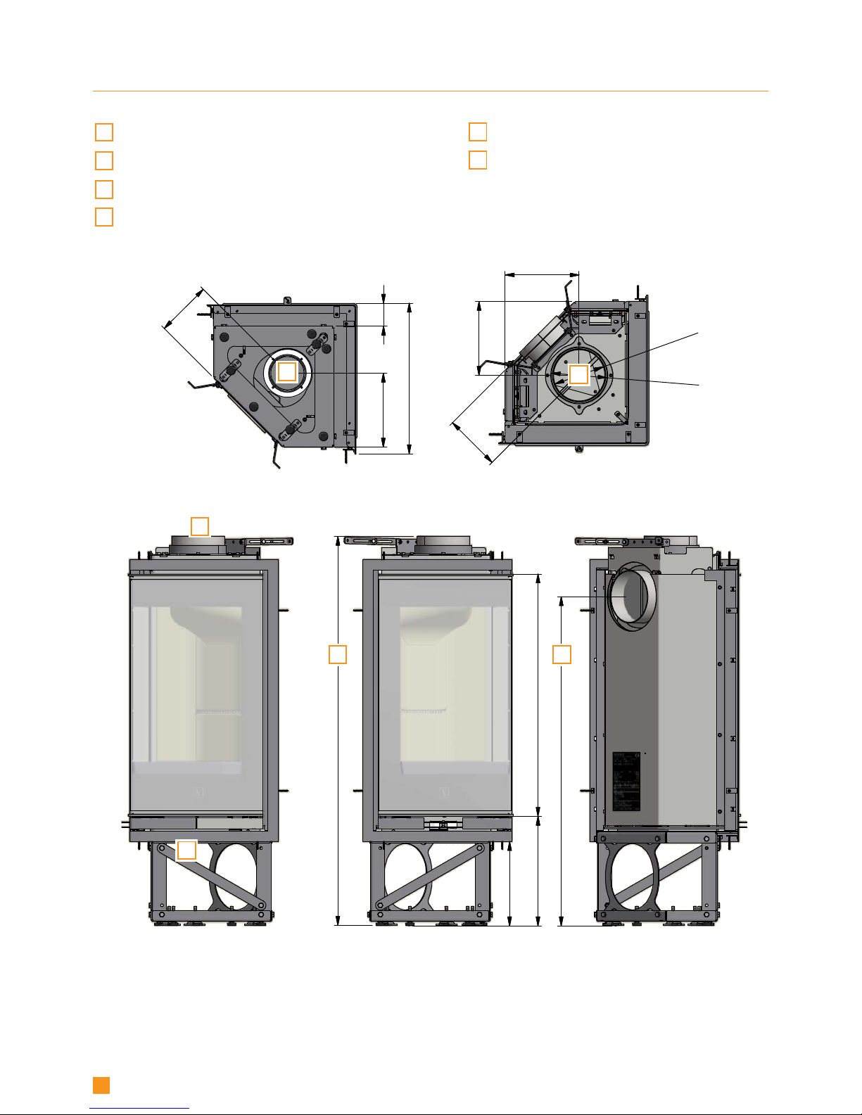
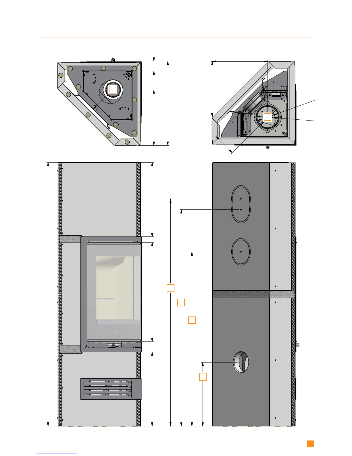
DIMENSIONAL DRAWING FOR SCAN 1008
A
Centre rear outlet
B
Height to the beginning of flue
connecting piece at top outlet
C
Centre of fresh air intake
D
Connecting piece for flue pipe (int. and ext. measure)
E
Centre to 90° curved elbow pipe 320 x320 mm
F
Centre to 2 x 45° elbow pipe 245x245 mm
All measures are in mm.
6
8
3
1
8
1
7
,
5
5
1
2
5
1
2
4
4
0
,
5
1
2
0
1
,
5
1
4
9
2
1
5
6
7
3
8
3
5
8
0
,
5
6
8
1
9
2
1
5
8
1
4
5
1
5
7
3
8
3
5
8
0
,
5
6
8
1
9
2
383
3
8
3
D
C
C
A
E
F
7
DIMENSIONAL DRAWING FOR SCAN 1008-S
8000000
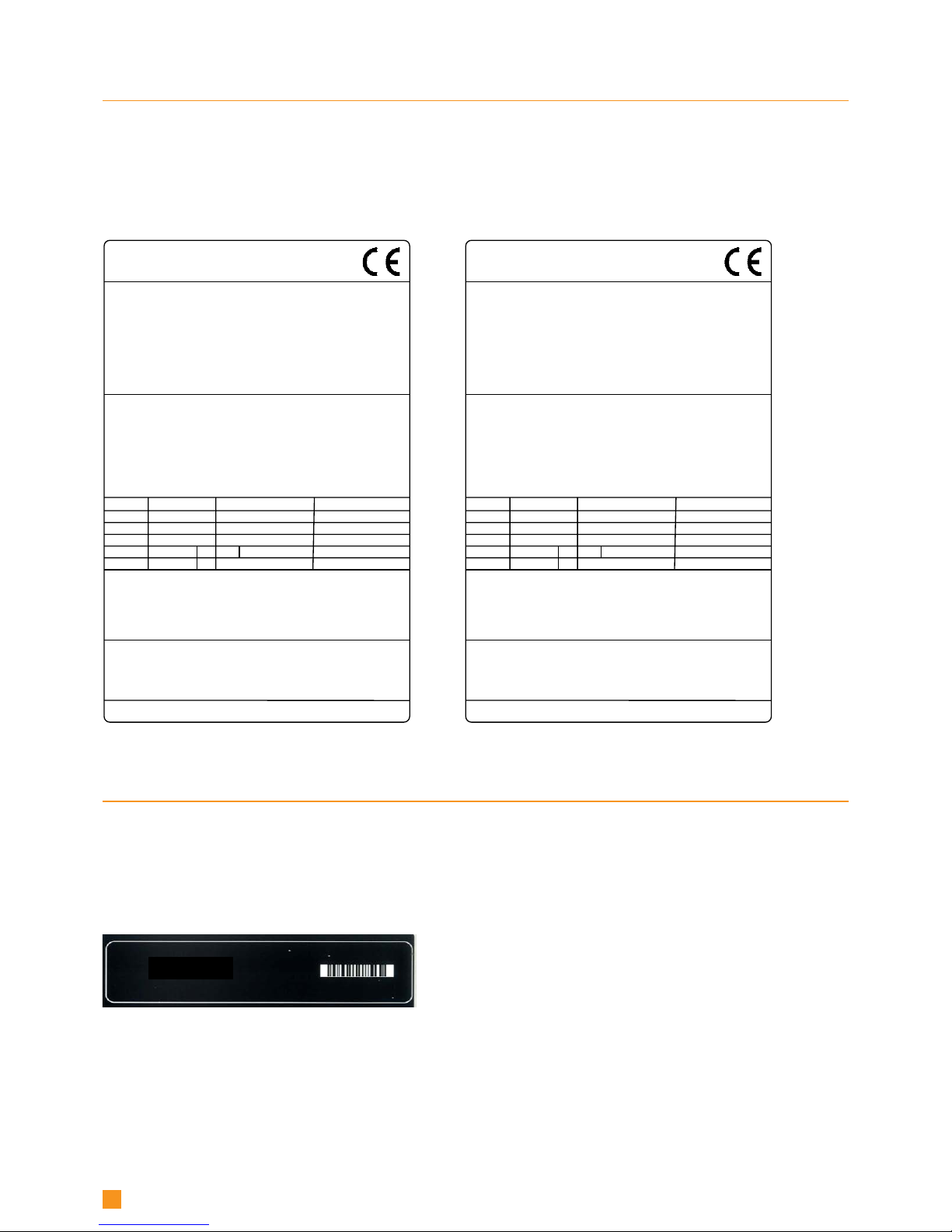
Scan 1008
Insert appliance fired by solid fuel
Standard:
Fuel type:
Operation type:
The appliance can be operated in a shared flue.
Country
EN 13229 DoP 90580601
Wood
Intermittent
EUR
Norway
Austria
Classification
Intermittent
Klasse 2
15a B-VG
Certificate/Standard
EN 13229
Approved by
Teknologisk Institut
Teknologisk Institut
Teknologisk Institut
Dust at 13% O2: 6 mg/Nm³
Flue gas temperature: 195°C
Nominal heat output: 6 kW
Efficiency: 84%
Scan A/S DK 5492 Vissenbjerg
Minimum distance to heat insulation:
Side: 25 mm - Back: 25 mm - Front: 800 mm
Minimum insulation:
CO emission at 13% O2:
See assembly- and instructions manual
Follow assembly- and instructions manual.
Use only recommended fuels.
Montage- und Bedienungsanleitung beachten.
Verwenden Sie nur empfohlene Brennstoffe.
1000 05-2018
0,06% 800 mg/Nm³
Germany Stufe 2 Teknologisk Institut
Scan 1008-S
Freestanding room heater fired by solid fuel
Standard:
Fuel type:
Operation type:
Reaction to fire: A1
Country
EN 13240 DoP 90580602
Wood
Intermittent
EUR
Norway
Austria
Classification
Intermittent
15a B-VG
Certificate/Standard
EN13240:2001
NS 3058
ELAB-2100-AUS
Approved by
Teknologisk Institut
Teknologisk Institut
Teknologisk Institut
Dust at 13% O2: 6 mg/Nm³
Flue gas temperature: 195°C
Nominal heat output: 6 kW
Efficiency: 84%
Scan A/S DK 5492 Vissenbjerg
Minimum distance to combustible materials
Side: 0 mm - Back: 0 mm - Front: 800 mm
Follow assembly- and instructions manual.
CO emission at 13% O2:
Follow assembly- and instructions manual.
Use only recommended fuels.
The appliance can be operated in a shared flue.
Montage- und Bedienungsanleitung beachten.
Verwenden Sie nur empfohlene Brennstoffe.
1000 05-2018
0,06% 800 mg/Nm³
Schweiz
Germany
LRV 11
Stufe 2
VKF
1. BlmSchV
8
PRODUCT REGISTRATION NUMBER
All Scan built-in stoves are provided with a product registration number. Please make a note of this number at the rear page of
this manual; you will always need to quote it when contacting your dealer or Scan A/S.
The product registration number is placed loose in the fireplace.
TYPE PLATE
All Scan built-in stoves are fitted with a type plate that specifies the approval standards and the distance to flammable materials.
The type plate is placed loose in the fireplace.
Type plate Scan 1008
Product registration number
Type plate Scan 1008-S

9
ASSEMBLY
TOOLS FOR THE MOUNTING OF THE BUILT-IN STOVE
¬ Spirit level ¬ 2.5 + 3 + 4 mm Allen key
¬ Cutting nippers ¬ 2 pcs. 10 mm spanners (or adjustable spanners)
¬ 8 mm box spanner
Extra tools for Scan 1008-S:
¬ Cordless electric drill ¬ Compass saw
¬ Tape measure/foot rule ¬ Large pair of scissors
¬ Caulking gun ¬ Torx slotted bits
¬ Pozidrive
LOOSE PARTS
The following loose parts are located in the built-in stove's combustion chamber:
¬ Oven mitt ¬ Two flue connection pieces (int. and ext. flue pipe)
¬ Gasket for flue connecting piece ¬ Screws for fastening the flue connection piece
¬ Ash container ¬ 8 fittings and screws for the surround
¬ Type plate and product registration number ¬ UK-blocking and screw
Extra parts for Scan 1008-S:
¬ Top plate
¬ Convection grate (complete)
¬ Surround kit consisting of:
Glue cartridge Calcium Silicate Surround
Joint tape 50 torx-slotted screws 6.0 x 90 (T30)
5 corner strips Felt knobs
ADDITIONAL ACCESSORIES
¬ Floor plates (see page 20)
¬ Cover plate for corner installation Scan 1008-S (See page 30)
¬ Convection grates (See page 31)
DISPOSAL OF PACKAGING
Your Scan built-in stove may come supplied with the following packaging:
Wood packaging
The wood packaging can be reused and after final use can be incinerated as a CO2 neutral
product or sent for recycling.
Polystyrene top Send for recycling or waste disposal.
Foam Send for recycling or waste disposal.
Plastic bags Send for recycling or waste disposal.
Stretch/plastic film Send for recycling or waste disposal.

10
FRESH AIR INTAKE
In a well-insulated house the air used for the combustion process has to be replaced. This particularly applies to houses with
mechanical ventilation. There are different ways of making sure that air is exchanged. The most important thing is to ensure that
there is a supply of air to the room where the wood stove is located. The external wall vent must be located as close to the wood
stove as possible, and you must be able to close it when you are not using the stove.
National and local building regulations must be followed with regard to connection of a fresh air intake.
CLOSED COMBUSTION SYSTEM
You should use the closed combustion system for the wood-burning stove if you live in a newly-built, airtight home.
External combustion air is connected through a ventilation pipe via the wall or floor.
It must be possible to shut off the ventilation pipe with a valve, when the stove is not in use. Minimum
Ø 100 mm ventilation pipe,
maximum length: 6 metres with a maximum of one bend. We recommend smooth steel pipes.
NOTE: if the stove has a fresh air connexion or closed combustion, the ventilation pipe must be open, when the stove
is in use!
LOAD-BEARING FOUNDATION
All items in our product range come under the category of lightweight fireplaces and stoves and do not normally require any reinforcement of the beam structure. They can be positioned on ordinary beams/floor.
You should of course make sure that the foundation on which the stove is positioned can indeed support the weight of the stove
and, where applicable, a steel chimney, if you have opted for this solution.
CONVECTION AIR
Scan 1008: The covering must contain holes for convection air.
Convection means that there is an air circulation ensuring that the heat is equally distributed in the room. It is important that the
demands concerning convection areas are observed. Scan 1008-S complies with these demands.
¬ Min. area for ingoing convection air: 300 cm
2
¬ Min. area for outgoing convection air: 500 cm
2
If there is not enough convection air, the covering may be damaged.
Convection air grids for Scan 1008 are available as an accessory.
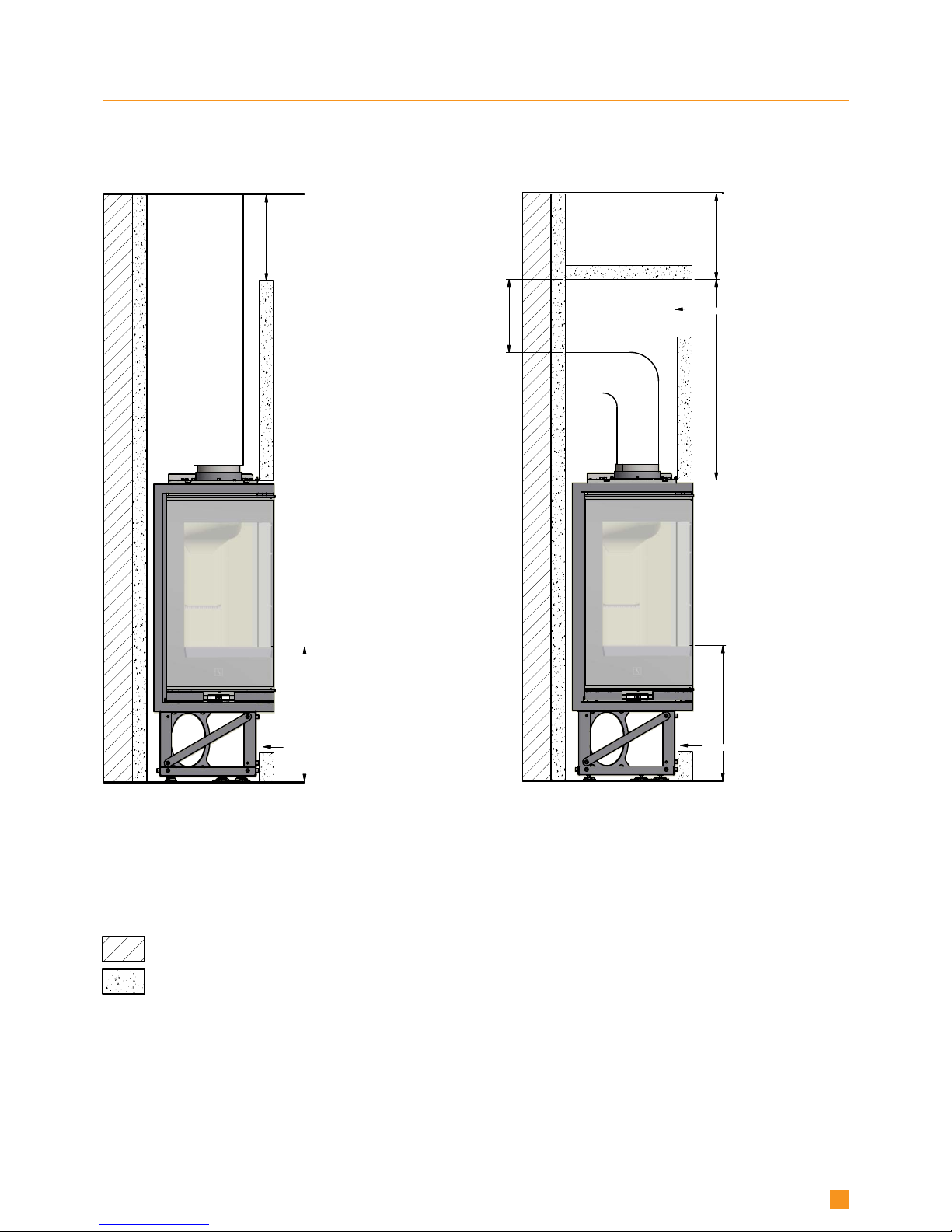
EXISTING CHIMNEY AND PRE-FABRICATED ELEMENT CHIMNEY
If you intend to connect your stove to an existing chimney, it makes sense to contact an authorised Scan dealer, or a local chimney sweep, for advice. These experts will also let you know if your chimney needs renovating.
¬ When connecting a pre-fabricated element chimney, follow the manufacturer’s connection instructions for the
relevant chimney type.
CONNECTION BETWEEN BUILT-IN STOVE AND STEEL CHIMNEY
Your Scan dealer, or local chimney sweep, can advise you on choosing a make and type of steel chimney. This ensures that the
chimney will match your wood-burning stove.

11
REQUIREMENTS FOR CHIMNEY
The chimney must have a minimum internal diameter of 148 mm and have a T400 designation, with G for the soot fire test.
If you opt to connect the built-in stove with an elbow pipe, you should use a curved elbow, as this gives a better draught.
If you connect the stove with a sharp elbow pipe, the cleansing lid must be placed in the vertical part so that the
horizontal part can be cleaned through here.
As a general rule, the length of the chimney should not be less than 4 metres, measured from the top of the stove. Specific
weather or installation conditions might require a different length.
The requirements to the chimney and the flue pipe in terms of safety distances must be met.
¬ Choosing the wrong length or diameter of steel chimney could impair functionality.
¬ Always comply exactly with the instructions provided by the steel chimney supplier.
INTERNAL INSTALLATION IN NON-FLAMMABLE MATERIAL
Scan 1008: There are no demands concerning the distance to non-flammable materials, but we recommend a distance of 25 mm
in order to facilitate the cleaning of the stove, the flue pipes and the chimney and to prevent possible damages to the wall.
DISTANCE TO FURNITURE
Distance to furniture: min. 800 mm.
You should however assess whether furniture or other items might become excessively dry due to being too close to the stove.
The stove is NOT to be built into flammable materials without the use of a fire wall!
SAFETY DISTANCE
European, national and local regulations concerning safety distances for wood-burning stoves and flue pipes must be complied
with.
2
5
m
m
Møbleringsafstand: 800 mm.
Brandbart materiale
Brandmur
2
5
m
m
250 mm
450 mm
5
8
0
m
m
2
5
m
m
2
5
mm
1
0
3
0
m
m
25 mm
2
5
m
m
3
5
0
m
m
2
0
0
m
m
*
*
*
*
12
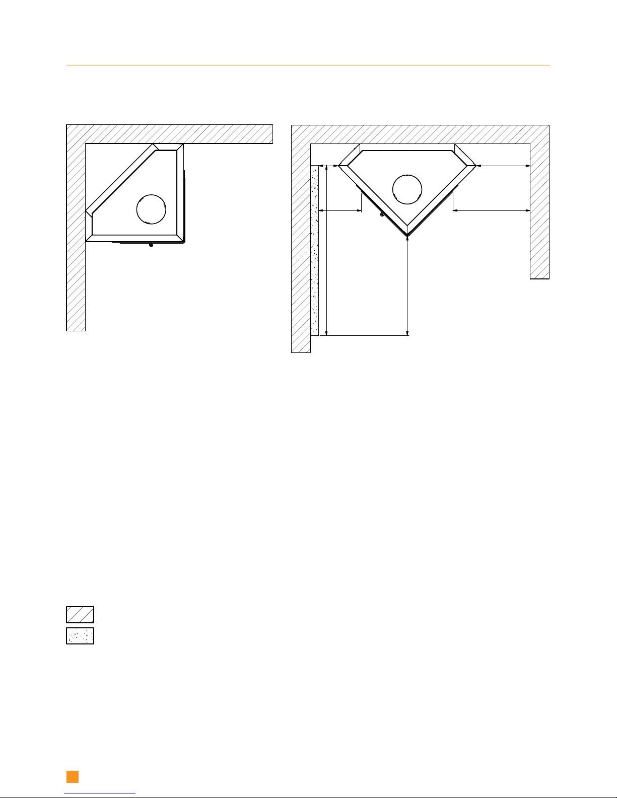
BUILDING INTO FLAMMABLE MATERIAL WITH FIRE WALL
Flammable material
Fire wall, e.g. 50 mm Jøtul Firewall, 110 mm brick
or other material with corresponding fireproof and
insulating abilities
All distances are in mm.
All distances are minimum distances
Distance to furniture: 800 mm. from glass
* Distance to glass
45° corner installation Parallel installation
- SCAN 1008
2
5
m
m
Møbleringsafstand: 800 mm.
Brandbart materiale
Brandmur
Loft
Møbleringsafstand: 800 mm.
Brandbart materiale
Brandmur
M
i
n
.
3
0
0
m
m
M
i
n
3
5
0
m
m
Min. 300 cm² konvektion
Loft
Møbleringsafstand: 800 mm.
Brandbart materiale
Brandmur
Min. 300 cm² konvektion
Min. 500 cm² konvektion
7
0
0
m
m
3
5
0
m
m
M
i
n
.
3
0
0
m
m
3
8
0
m
m
**
**
13
BUILDING INTO FLAMMABLE MATERIAL WITH FIRE WALL
Flammable material
Fire wall, e.g. 50 mm Jøtul Firewall, 110 mm brick
or other material with corresponding fireproof and
insulating abilities
All distances are in mm.
All distances are minimum distances
Distance to furniture: 800 mm. from glass
** Distance to flammable floor
Installation with an insulated, vertical flue pipe
Installation with an un-insulated elbow pipe
convection
convection
convection
The distance to fire wall (brick) depends on the use of an
insulated flue pipe with min. 30 mm insulation all the way
down to the insert
- SCAN 1008
2
5
m
m
Møbleringsafstand: 800 mm.
Brandbart materiale
Brandmur
250 mm 450 mm
5
8
0
m
m
9
9
2
m
m
114 mm
313 mm
*
*
*
14
BUILDING INTO FLAMMABLE MATERIAL WITH FIRE WALL
Flammable material
Fire wall, e.g. 50 mm Jøtul Firewall, 110 mm brick
or other material with corresponding fireproof and
insulating abilities
All distances are in mm.
All distances are minimum distances
Distance to furniture: 800 mm. from glass
* Distance to glass
45° corner installation Parallel installation
- SCAN 1008-S
1
2
15
REMOVE PACKAGING
Before installing the stove, check that it has no damages.
NOTE: Do not touch the glass
Remove the 4 screws from the
lifting bracket
Then remove the screws connecting the lifting bracket with the
built-in stove. Remove the lifting
bracket and the wood frame
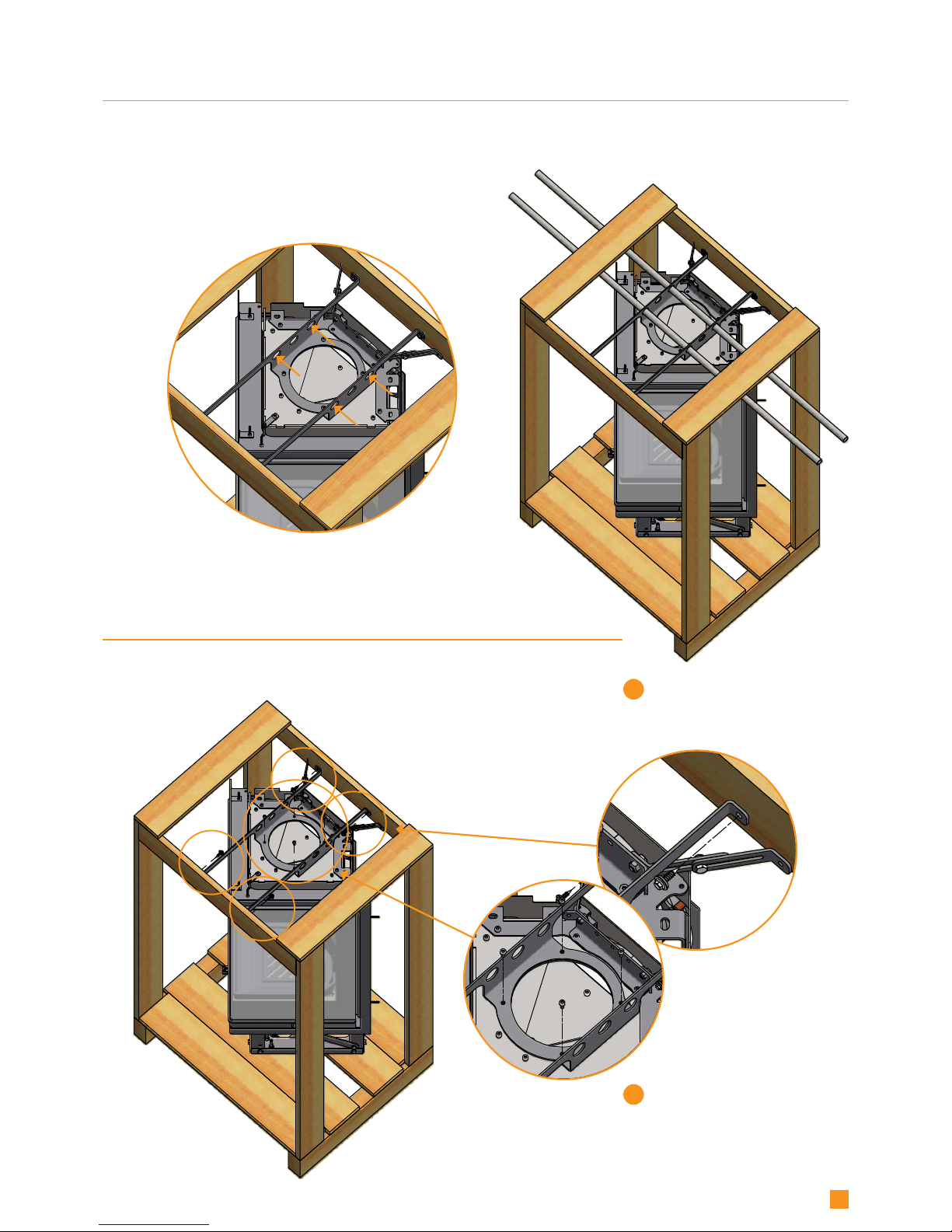
USING THE LIFTING FITTINGS
When moving the insert before it is removed from the pallet, you must use the lifting fittings in order to avoid twisting the glass.
Install two steel tubes with a diameter of max. 25 mm thrugh the holes in order to lift the stove.
PLEASE NOTE: If the insert is to be moved, after it has been removed
from the pallet, the door must be opened or dismounted!

3
Scan 1008
Scan 1008-S
16
REMOVE PACKAGING
NOTE: The stove must be taken off the pallet by removing the screws. Do not knock off the pallet, as this can damage the stove.
The built-in stove is mounted
on the pallet with 6 screws
(Scan 1008)/4 screws (Scan
1008-S). Please remove these.
NOTE: it is important that the
door is not opened after
removing the screws, as the
stove may easily tilt!

A ( 1 : 5 )
A
A ( 1 : 5 )
4x
A ( 1 : 5 )
A
17
Connection piece
for external flue
pipe
Connection piece for
internal flue pipe
FITTING THE FLUE CONNECTION PIECE
The gasket for the flue connection piece, flue connection piece and screws can be found in the stove’s combustion chamber.
Gasket
IN THE TOP OUTLET
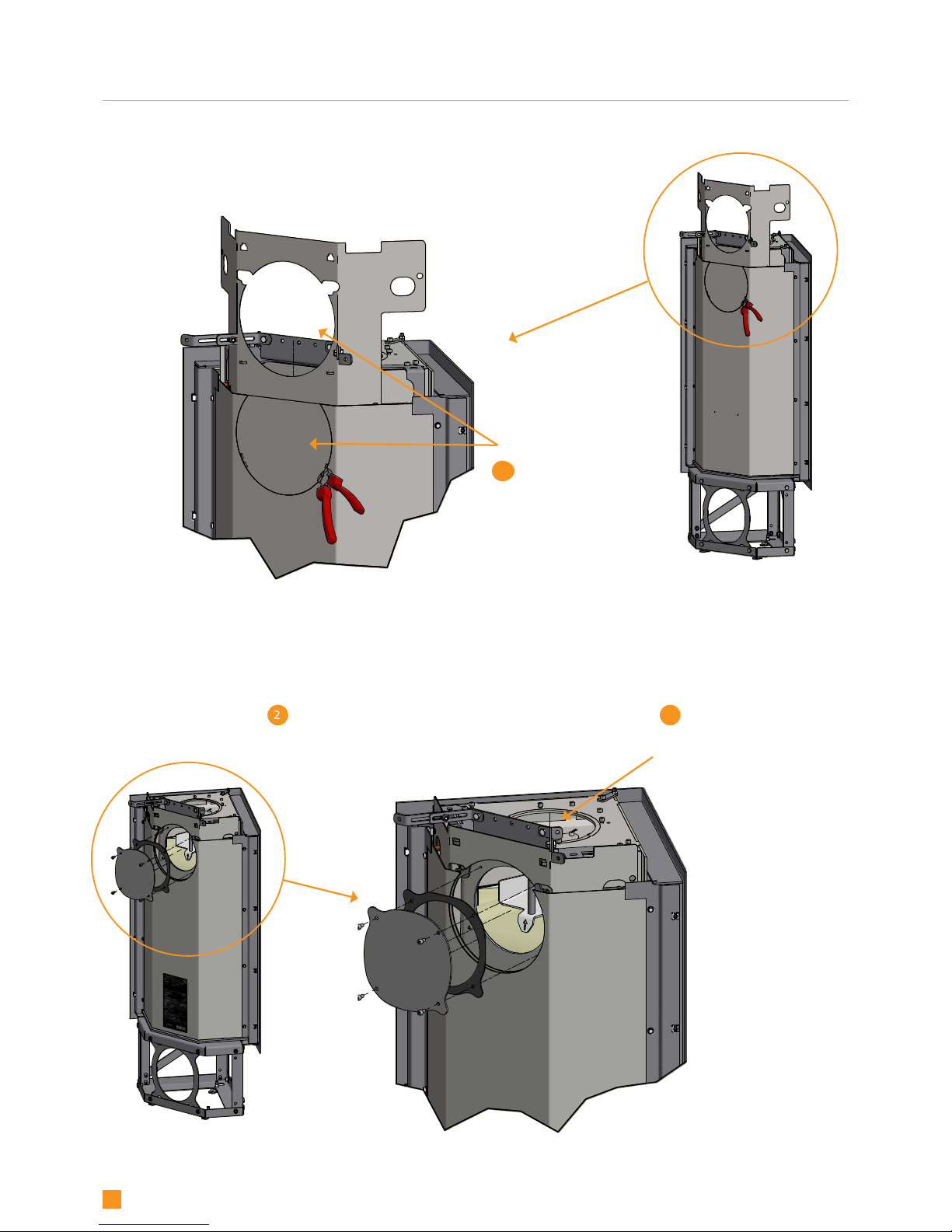
B
2 3
B
1
18
FITTING THE FLUE CONNECTION PIECE IN THE REAR OUTLET
The gasket for the flue connection piece, flue connection piece and screws can be found in the stove’s combustion chamber.
Using cutting pliers, cut
off the cover plate from
the rear plate and the heat
shield at its securing points.
Remove the gasket
and the cover from the
stove’s rear outlet.
Fit the gasket and the cover in the
stove’s top outlet and tighten it.
Reposition the top module.

A ( 1 : 5 )
4x
4
D ( 1 : 5 )
E
Bagklap fjernes ved at løfte op og "vippe" øverste kant ud
19
Connection piece for
external flue pipe.
Tighten the flue connection piece
with the delivered screws.
FITTING THE FLUE CONNECTION PIECE IN THE REAR OUTLET
Gasket
DOOR (SELF-CLOSING)
The door is delivered without self-closing function.
NB: If you want a self-closing door, the spring can be tightened by turning the long screw (inside the spring) clockwise
using a Allen key (5 mm) and at the same time tightening the pointed screw at the bottom with a Allen key (2.5 mm).
Long screw
Pointed screw

2
1
D ( 1 : 5 )
E
Bagklap fjernes ved at løfte op og "vippe" øverste kant ud
E
3
20
FLOOR PLATE
If you are placing the stove on a flammable floor, you must comply with the national and local regulations on the size of any
non-flammable subsurface required to cover the floor around the stove.
Your local Scan dealer can advise you on regulations concerning protection of flammable materials in the vicinity of your stove.
The floor plate’s function is to protect the floor and flammable material against any sparks that may occur.
NOTE: The stove must be levelled, before the stove is moved into place.
Large shaped floor plate in clear or
smoke-coloured glass
Small floor plate in clear or
smoke-coloured glass
HEIGHT ADJUSTMENT OF THE BUILT-IN STOVE
Scan 1008 is delivered on a small rack. If you want to install the stove in a higher position, the rack can be blocked up on a solid
foundation of non-flammable material.
We recommend to fasten the
fittings with the two screws to the
floor.
The stove is equipped with eight
adjustment screws, of which three
are used to ensure that the stove
is level.
Fasten the five remaining
screws until they meet resistance in order to ensure that
the built-in stove is stable.
(ACCESSORY)

G
G
G
21
FASTENING TO THE REAR WALL
The built-in stove has two adjustable fittings for the fastening of the stove to the rear wall.
Fastening corner Parallel fastening

1
2
D ( 1 : 5 )
22
DISMOUNTING OF THE FRAME
The built-in stove is delivered with the frame mounted on the stove. The frame can stay on, while making the surround, but if you
want to dismount it, it is done in the following way.
First dismount the door:
Unscrew the pointed
screw using an Allen key
(2.5 mm). Loosen and
remove the long screw
with the spring
The door can now be removed

3
4
A ( 1 : 5 )
A ( 1 : 5 )
A ( 1 : 4 )
5
23
DISMOUNTING OF THE FRAME
Remove the screws holding
the frame
Remove the screw on the
frame
The frame can now be removed

4
0
m
m
1
2
0
m
m
4
0
m
m
1
2
0
m
m
24
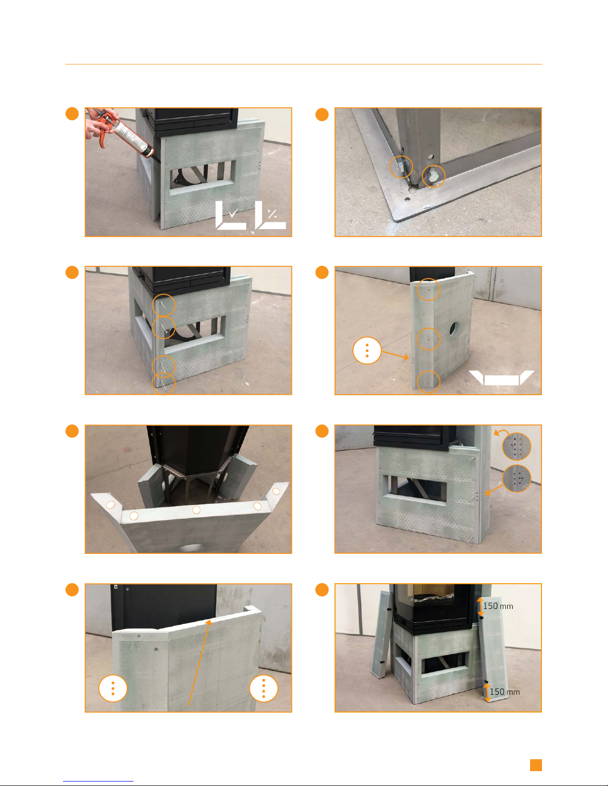
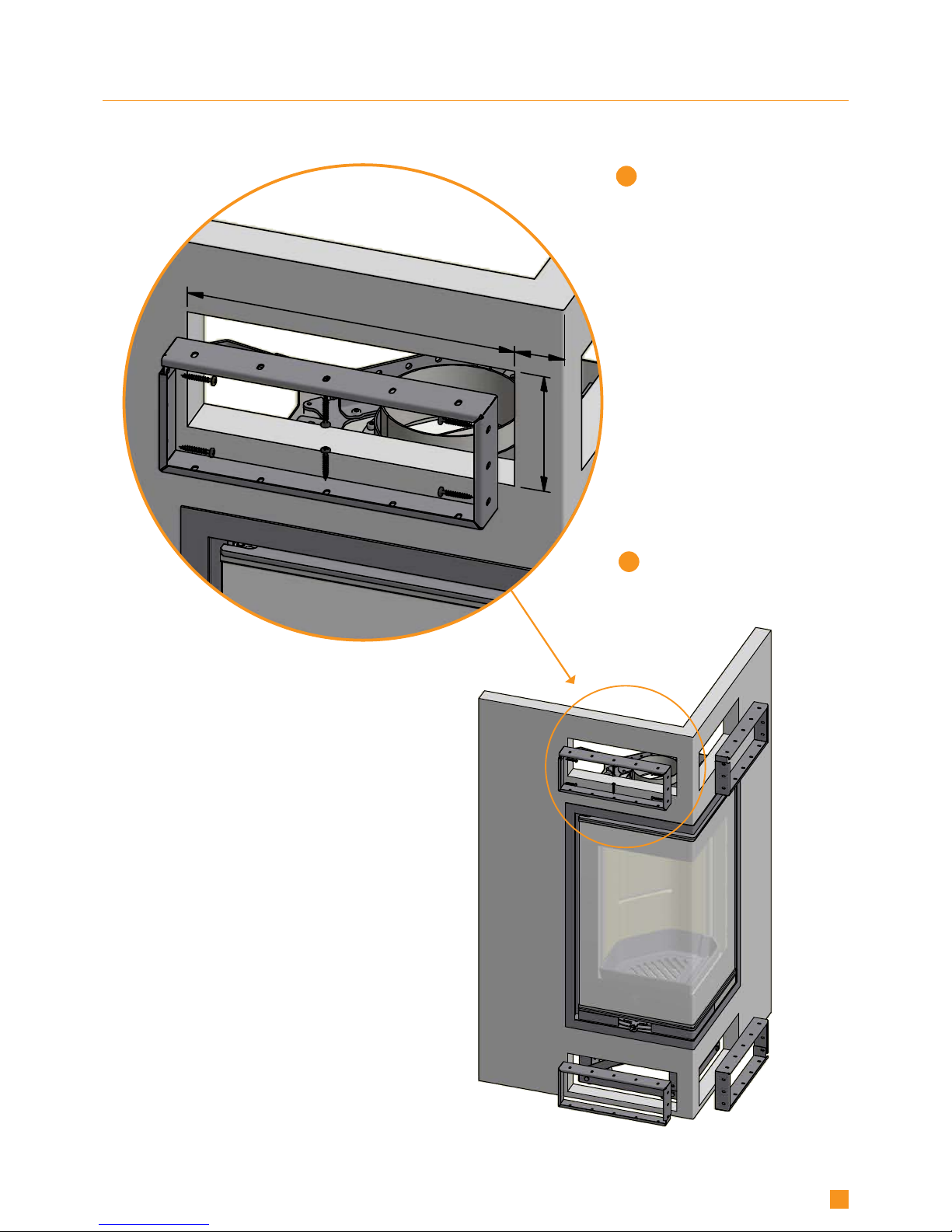
BUILDING AROUND THE FRAME
The built-in stove is delivered with 8 distance fittings with screws in order to ensure a distance between the rear of the trim to
the surround.
As a natural consequence of the thermal expansion properties of steel, the stove and the trim will expand and “raise”, when the
stove is in use. In order to prevent the trim from scraping against the surround and leave visible scratches, it is important to
mount these fittings as shown. The fittings allow a distance of 2 mm before a possible layer of filler and paint.
ATTENTION! This illustration is only
to show the position of the fittings
(only Scan 1008).
For positioning of the fittings on
Scan 1008-S, see page 26-27.
Normally the surround will consist
of more elements that are built up
around the insert with these fittings
mounted in advance.
PLEASE NOTE!
The fittings must fit tightly
against the surround!

DATO:
SIGN:
Krog Iversen & Co A/S
DK-5492 Vissenbjerg
©
TG.NR:EMNE:
90580060
23-02-2018
ken
VÆGT:
N/A
52
5
2
52
5
2
DATO:
SIGN:
Krog Iversen & Co A/S
TG.NR:EMNE:
90580060
Scan 1008 - indbygning i ramme
23-02-2018
ken
VÆGT:
AREAL:
N/A
N/A
52
5
2
52
5
2
50
50
25
BUILDING AROUND THE FRAME
PLEASE NOTE: The frame is adjusted from the factory so that you can max. use 50 mm material around the frame.
7
6
4
50 mm
350 mm
2
3
5
D
4
0
m
m
1
2
0
m
m
1
26
BUILDING AROUND THE FRAME
PLEASE NOTE! The insert must be level, before the surround is mounted!
The stove can be mounted at a distance from the wall and then be pushed into its final position afterwards.
Mount the two fittings on the front pieces
with the short screws
The hole patterns must turn against the rear side of
the stove when pulling the front pieces in place
Carefully tilt the stove a little bit and mount 8 felt knobs
at the bottom of the base. Avoid touching the glass!
Pull the front pieces behind the frame from the sides
On the material of the surround there is a hole pattern.
Make sure to follow the pattern as shown subsequently
- SCAN 1008-S
PLEASE NOTE!
Check that the bottom is even
before the mounting!
FOLLOW THE
MOUNTING INSTRUCTIONS
CAREFULLY!
PLEASE NOTE! The fittings must fit tightly
against the surround!
8
9
9
150 mm
150 mm
13
12
15
11
14
10
27
Mount the side pieces with two fittings.
NOTE: These do not have a hole pattern
Then mount the whole rear piece with the front
using glue and three screws in each side
Turn the bottom of the rear piece upwards
and mount five felt knobs
Push the front pieces together and glue them
so that the bevels fit together
Important! When mounting the surround plates, the
rear side must fit closely against the head of the bolt
Put together the three rear pieces with glue
and three screws in each side
It is important that the groove turns upwards,
when the rear piece is mounted!
BUILDING AROUND THE FRAME- SCAN 1008-S
Screw the front plates together with four screws

20
22 23
19
21
17
16
18
28
Glue the side pieces to the rear piece
and fasten with two screws
Distance from wall to rear edge of fitting: ca 105 mm
Mount the fitting for the whole rear piece
BUILDING AROUND THE FRAME
If needed, make a hole for the flue pipe on the upper
rear piece. Use a compass saw
Hole for rear
outlet
Hole for 90°
curved elbow pipe
320x320 mm
Hole for 2 x 45°
elbow pipe
245x245 mm
- SCAN 1008-S
Turn
upwards!
Mount the side pieces on the bottom pieces
It is important that the fittings are placed correctly!
Glue the side pieces to the rear piece
and fasten with two screws
Side piece
Bottom piece
Glue the three upper rear pieces together with the side pieces and fasten with three screws
26 27
25
28
24
50 mm
350 mm
30
B
B
29
31
29
Moun tthe two upper front pieces with two fittings
BUILDING AROUND THE FRAME
It is important that the fittings are placed correctly
and moounted as shown!
Glue together the two upper front pieces and fasten with
three screws before mounting them in the frame at the top
The fitting is used for stabilizing the stove
for the whole surround
It is important that the distance fitting fits tightly
against the rear side of the frame!
- SCAN 1008-S
It is important that the surround does not "rest"
on the frame!
Glue the upper front piece to the whole rear piece and
fasten with three screws at each side
Mount self-adhesive joint tape in the filling trace.
Then cut the corner strips in appropiate lengths
with a large pair of scissors
34
3
8
3
5
8
0
,
5
6
8
1
9
2
383
3
8
3
33
32
30
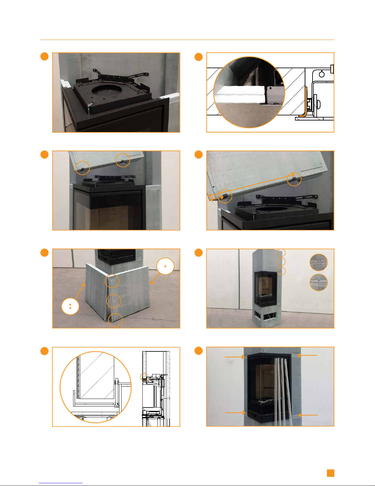
Place the top plate, and if needed the cover plate for
corner installation (can be bought separately)
Top plate
Cover plate
(Accessory)
BUILDING AROUND THE FRAME- SCAN 1008-S
We recommend to dismount the frame. Alternatively it
is important to cover the frame before filling.
We recommend to fill twice, before the surround is
ready to be painted and the convection grates are
mounted.
Follow the instructions on next page
"Mounting of convection grate"
The corner strips can be mounted on all edges
using glue or filler
3
5
7
1
3
5
,
5
5
2
,
5
1
2
3
5
7
1
3
5
,
5
5
2
,
5
31
Cut a hole in the wall according to
the indicated measures
(Only Scan 1008)
Fasten the metal frames
with the six screws
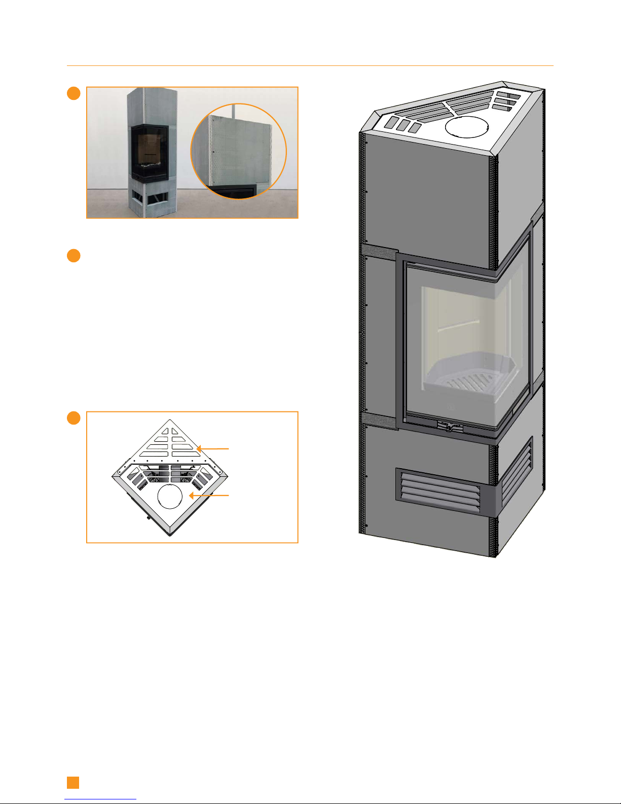
MOUNTING OF CONVECTION GRATE
Scan 1008-S is delivered with cut-out holes in the surround and a convection grate in black.
(If you want a white convection grate, this can be bought separately).
(ACCESSORY SCAN 1008)

3
5
7
1
3
5
,
5
5
2
,
5
3
32
MOUNTING OF CONVECTION GRATE (ACCESSORY SCAN 1008)
Put the four magnets on each corner
of the metal frames. Then mount the
convection grates.
NOTE! It is important that the magnets are flush with the outer fire wall
plate.

33
INSTRUCTIONS FOR USE
CB-TECHNOLOGY (CLEAN BURN)
The stove is equipped with CB technology. In order to ensure optimal combustion of gases released during the combustion
process, air passes through a specially developed system of channels. The heated air is conducted into the combustion chamber
through the holes in the rear lining of the combustion chamber and at the baffle plates. This airflow is controlled by the rate of
combustion and cannot therefore be regulated.
NOTE: The wood must never be placed higher than the tertiary holes at the rear of the burn chamber (This does not apply at a
cold start).
BAFFLE PLATE
The baffle plate is located in the upper part of the combustion chamber. The plate holds back smoke, making sure it stays inside
the combustion chamber for a longer time before escaping through the chimney. This reduces the flue gas temperature as the
gases have more time to dissipate heat to the stove.
The baffle plate must be removed for sweeping; see “Maintenance”. Note that the baffle plate is made of porous, ceramic material, and is liable to break easily. You should therefore handle it with care.
The baffle plate is subject to wear and tear and not covered by the warranty.
ASH CONTAINER
¬ Open the door of the stove to access the ash container under the combustion chamber.
¬ The ash container must always be closed during operation.
¬ The ash container must not be become too full and must therefore be emptied at regular intervals.
¬ Never empty ashes into a flammable container. Ashes can contain glowing embers long after you finish operating
the stove.
PRIMARY AIR
The primary air regulation mechanism is used to light the fire or to boost the burning process, when you put
wood on. The primary air can be used during a continious firing with hard wood like oak and beech. If you use
softer wood types like birch and pine, the primary air can stay closed.
SECONDARY AIR
Secondary air is pre-heated and fed indirectly to the fire. At the same time, the secondary air
flow cleans the glass pane to prevent build-up of soot. If you over-restrict the secondary airflow,
soot can build up on the glass pane. The secondary air flow determines the heat output from
your wood stove.
Tertiary holes

1
2
3 4
5
34
ADJUSTMENT OF PRIMARY- AND SECONDARY AIR
The primary air (1) is controlled by the lower damper (shown with a match and a small flame).
The secondary air (2) is controlled by the upper damper (shown with a big flame).
When firing a cold stove, pull both dampers to the right. The primary air damper will meet a stop (3).
Lift up the handle for the primary air damper and then pull it all the way to the right (4).
See our video about correct firing and adjustment of primary- and secondary air on www.scan.dk or scan the QR-code on next
page.
ADJUSTMENT OF PRIMARY- AND SECONDARY AIR/WARM STOVE
When the stove is warm, adjust the primary- and secondary air dampers to 20/80 (5).
As long as the stove is warm, the primary air is only to be adjusted within the area before the stop (3).
Primary air: 0-20% at soft wood
Secondary air: 70-80%
Damper for
primary air
Damper for
secondary air
When firing a cold stove, lift
the damper up over the stop
and all the way to the right.
When the stove is warm, you can
adjust the primary- and secondary
air to:
20% primary air
80% secondary air
Pull the primary air damper
to the right, until you reach
a stop.
Dampers for
primary- and
secondary air.
/COLD STOVE
NOTE: See page 43 "Mounting the UK - blocking and screw"

35
INSTRUCTIONS FOR HEATING
ENVIRONMENTALLY FRIENDLY OPERATION
Avoid turning down your wood-burning stove to the point where no flames are
visible from the wood, as this leads to poor combustion and low efficiency. The
gases released from the wood will not be burnt off due to the low temperature
in the combustion chamber. Some of the gases will condense in the stove and
flue system as soot, and this could lead to your chimney catching fire at a later
point. The residual smoke which exits the chimney will pollute the surrounding
area and cause an unpleasant smell.
LIGHTING
We recommend the use of fire lighters, or similar products, which are available from your Scan dealer.
Using fire lighters helps light the wood more quickly and keeps the combustion process clean.
See our video about correct firing on www.scan.dk or scan the QR-code.
NOTE: Never use liquid lighting fuels!
”TOP DOWN” LIGHTING
"Top down" lighting is a more environmentally friendly way of lighting the fire and helps to keep the glass area as clean as possible.
Do as follows for a correct ”top down” lighting:
¬ 4 pieces of wood approx. 19-20 cm long with a weight of approx. 0.4-0.5 kg per piece
¬ 12-20 thin pieces of firewood of about 19 cm in length, with a total weight of approx. 1 kg
¬ 3-4 fire lighters
1
Place the pieces of wood, firewood and fire lighters in the combustion chamber as shown below
2
Set the primary and secondary air controls to maximum for 20-30 minutes (See "Instructions for use")
3
When the large pieces of wood have caught fire, you can adjust the primary- and secondary air to the desired level
NOTE: The wood must never be placed higher than the tertiary holes at the rear of the burn chamber (This does not apply at a
cold start).
NOTE!
No matter how good your chimney is,
it will not perform well, if you do
not use it correctly. Equally, a poor
chimney may well give you acceptable
results, if you use it correctly
Scan the QR-code
and see our video
about correct firing.
Fire lighters
Tertiary holes
Pieces of
firewood
Wood

36
VERTICAL LIGHTING
A vertical lighting also ensures an environmentally friendly lighting and helps to keep the glass optimally clean.
For a vertical lighting, you need the following:
¬ 4 pieces of wood approx. 19-25 cm with a weight of approx. 0.4-0.5 kg per piece
¬ 8-10 thin pieces of firewood with a total weight of approx. 300-400 g
¬ 3-4 fire lighters
1
Place the pieces of wood, firewood and fire lighters in the combustion chamber as shown below
2
Set the primary and secondary air controls to maximum for 20-30 minutes (See "Instructions for use")
3
When the large pieces of wood have caught fire, you can adjust the primary- and secondary air to the desired level
CONTINUOUS OPERATION
It is important to obtain as high a temperature as possible in the combustion chamber. This results in best possible use of the
stove and fuel, as well as achieving clean combustion. In this way you will avoid build-up of soot on the combustion chamber
lining and glass pane. During operation, you should not see any smoke; just a movement in the air that indicates combustion is in
progress.
¬ After completing the lighting phase, you should have a good layer of embers in the stove; you can then start operation of it
properly.
¬ Add two pieces of wood at a time: they should be about 0.4 to 0.6 kg in weight and about 20 cm long.
NOTE: The wood must catch fire quickly. This is why we recommend setting the primary air flow fully open.
NOTE: Operating the stove at too low a temperature and with too little primary air can lead to gases igniting, which can damage
the stove.
¬ When adding wood, always open the glass door carefully to prevent smoke escaping.
¬ Never add wood, while the fire is burning nicely.
WARNING ABOUT OVER-FIRING
If the stove is continiously fired with larger amounts of wood than recommended and/or receives too much air, this can cause a
heavy heat development liable to damage both stove and the surrounding walls. We therefore recommend that you always observe the max. recommended amount of fuel (See under ”Technical Data”).
Fire lighters
Pieces of
firewood
Wood

37
FIRING IN THE SPRING OR AUTUMN
In the spring/autumn transition period, where there is less need for heating, we recommend you light the stove “top down” once,
perhaps adding just two pieces of wood to ensure that the combustion chamber lining burns clean again.
THE FUNCTION OF THE CHIMNEY
The chimney is the wood-burning stove’s motor; its performance determines how well your stove will work. The draught in the
chimney creates negative pressure in the wood-burning stove. The negative pressure draws the smoke out of the stove and takes
in air through the combustion air damper to fuel the combustion process. Combustion air is also used for the airwash system
that keeps the glass clear of soot.
The draught in the chimney is created by the difference in temperature inside and outside the chimney. The higher the difference in temperature, the better the draught. This is why it is important that the chimney reaches operating temperature before
you reduce the damper settings to restrict combustion in the stove (a brickwork chimney will take longer to reach operating
temperature than a steel chimney). It is very important that the operating temperature is reached as quickly as possible on days
when the draught in the chimney is poor due to unfavourable wind and weather conditions.
You need to get a few flames going as quickly as possible. Chop the wood extra thin; use an extra fire lighter etc.
¬ After longer periods without use, you must check the chimney flue for blockages.
¬ You can connect several units to the same chimney. You should however first check the relevant regulations in this respect.
USING THE STOVE IN VARIOUS WEATHER CONDITIONS
The way the wind affects the chimney can have a big impact on how your stove reacts under various wind loads; you may need to
adjust the airflow to achieve good combustion. Fitting a damper in the flue pipe may also help, as it will allow you to regulate the
draught under changing wind loads.
Fog and mist can also have a big impact on chimney draught; you may need to use other settings for the combustion air to
achieve good combustion.
GENERAL NOTES
PLEASE NOTE! Parts of the wood-burning stove, especially the outer surfaces, become hot during use. Due care should be exercised.
¬ Never empty ashes into a flammable container. Ashes can contain glowing embers long after you finish operating the stove.
¬ When the stove is not in use you can close the dampers to avoid a draught through the stove.
¬ If the stove has not been used for some time, you should check the flue passageways for potential blockages before relighting.
NOTE: Never place flammable material in the radiation zone of the stove!
CHIMNEY FIRE
In the event of a chimney fire, keep the stove door, ash drawer, and all dampers on the stove closed. In an emergency, call the fire
service.
¬ We recommend that you get a chimney sweep to check the chimney before using the stove again.

38
The various woods have different calorific values. In other words,
for certain species of wood, you will need to use a greater quantity
to achieve the same heating performance. This Instuction Manual
assumes that you will be using beach, which has a very high calorific value and is also the easiest wood to get hold on. If you use oak
or beech as fuel, you need to bear in mind that these wood types
have a greater calorific value than for example birch. To avoid any
risk of damage to the stove, you should therefore make sure to use
less fuel in these cases.
CALORIFIC VALUE OF THE WOOD
Wood types kg Drywood/m3Compared to beech
Hornbeam 640 110%
Beech/Oak 580 100%
Ash 570 98%
Maple 540 93%
Birch 510 88%
Pine 480 83%
Fir 390 67%
Poplar 380 65%
HANDLING OF THE FUEL
SELECTING WOOD/FUEL
You can use any type of wood as fuel. However harder woods, such as beech or ash, are generally better for heating, as they burn
more evenly and create less ash. Other woods, such as maple, birch and spruce, are excellent alternatives.
PREPARATION
The best fuel is obtained where the tree has been felled and the wood sawn and split before May 1st. Remember to cut the wood
to match the size of the combustion chamber. We recommend a diameter of 6-10 cm. The length should be about 6 cm shorter
than that of the combustion chamber to leave enough space for air to circulate. If the diameter of the wood is greater than the
above, it should be split down its length. Wood that has been split dries faster.
STORING
You need to store the sawn and split wood in a dry place for 1-2 years before it will be dry enough to burn. Wood dries faster if
you stack it in an airy place. Before using it, it is a good idea to store the wood for a few days at room temperature. Remember
that wood absorbs moisture from the air during autumn and winter.
MOISTURE
To avoid problematic impact on the environment and to ensure optimum operating economy, the wood should be perfectly dry
before it can be used as fuel. If you use wood that is too damp, most of the heat it produces will be used up in evaporating the
water. The stove will accordingly not increase in temperature, nor emit heat to the room as a result. This is obviously poor economy, and it will cause soot build-up on the glass pane, in the stove and in the chimney. Operation using moist wood also pollutes
the environment.
¬ Maximum wood moisture content should not exceed 20%. A moisture content of 15-18% will deliver best efficiency.
¬ An easy way of checking wood moisture content is to knock the ends of the two pieces of wood together. If the wood is moist,
the sound will be slightly muffled.
USE OF THE FOLLOWING AS FUEL IS ILLEGAL
NOTE: It is absolutely prohibited to fire with painted, pressure impregnated or glued wood, or sea driftwood. Nor should you
ever burn chipboard, plastics, or treated paper. These contain substances that are hazardous to human health, to the environment, your stove, and your chimney. In short - make sure you only use proper wood.

39
MAINTENANCE
SWEEPING THE CHIMNEY AND CLEANING THE STOVE
Follow national and local regulations for sweeping the chimney. We recommend having the stove cleaned regularly by a chimney
sweep.
Before cleaning the stove and sweeping the chimney, the baffle plate must be removed (See "Removing the baffle plate").
NOTE: All service and reparation must be done, when the stove is cold.
CHECKING THE STOVE
Scan A/S recommends that you check your stove thoroughly after sweeping/cleaning. Check all visible surfaces for cracks.
Check that all joints are tight and that the gaskets are correctly seated. Worn or deformed gaskets should be replaced.
SERVICING
We recommend that the stove is thoroughly serviced at least every two years by a qualified fitter. Remember only to use original
spare parts.
The service should include the following:
¬ Lubricate hinges using copper grease
¬ Check the gaskets. Replace any that are broken or have turned hart
¬ Check the combustion chamber lining and the grate
¬ Check heat-insulating materials
COMBUSTION CHAMBER LINING
Slight cracks can appear in the combustion chamber lining due to moisture
or sudden heating/cooling. These cracks have no influence on the output or
lifetime of your stove. However, if the lining starts to crumble and fall out,
you must replace it.
The combustion chamber lining is not covered by the warranty.
GASKETS
All wood-burning stoves have seals made of ceramic material fitted to the stove, the door and/or the glass. These seals are
subject to wear and tear and must be replaced when necessary.
Gaskets are not covered by the warranty.
PAINTED SURFACES
Clean your wood-burning stove by wiping it down with a dry, lint-free cloth.
If the paint finish gets damaged, you can purchase repair paint in spray form from your Scan dealer. As slight differences in
colour shade are possible, we recommend you spray a larger area to achieve a natural blend. For best results, apply repair spray
when the stove is warm enough for you to just keep your hand on it, but no hotter.
NOTE: Make sure to air the room thoroughly after applying spray paint.
Combustion chamber lining

1
2
40
CLEANING THE GLASS
Our wood-burning stoves are designed to prevent serious soot build-up on the glass. The best way to achieve this is to make sure
you have a good supply of combustion air. It is also very important that the wood is dry and the chimney correctly dimensioned.
Even if you operate the stove in accordance with our instructions, a slight film of soot may still accumulate on the glass.
You can
easily remove this film by wiping the glass down with a dry cloth and then with a cloth dampened with glass cleaner.
¬ Please note that the glass cleaner is not to get into contact with the gaskets, as this can discolour the glass permanently.
¬ The glass cleaner must not come into contact with the painted surfaces, as these can be damaged.
REMOVING THE BAFFLE PLATE AND THE BAFFLE UNIT
Be very careful when removing the baffle plate from the stove.
After the baffle plate has been removed, the baffle unit can be dismounted.
Lift up the baffle unit a little and tip it slightly backwards until it is free of the hole (1). Then slowly pull out the unit, until it is
free of the rear rails (2).
DISPOSAL OF STOVE PARTS
Steel/cast iron Send for recycling
Glass Dispose of as ceramic waste
Combustion chamber lining Vermiculite and chamotte are not recyclable. Dispose of as waste.
Baffle plate Vermiculite is not recyclable. Dispose of as waste.
Gaskets Dispose of as waste
Baffle plate
Baffle unit

41
TROUBLESHOOTING
SMOKE ESCAPING
¬ Damp wood ¬ Chimney not drawing properly
¬ Chimney is not properly dimensioned for the built-in stove ¬ Check if the smoke gas pipe/chimney are blocked
¬ Is the chimney the right height for its surroundings? ¬ Vacuum in the room
¬ At rear outlet, check that the flue pipe does not ¬ The door is opened before the embers have burned down
obstruct the chimney draught sufficiently
WOOD BURNING TOO QUICKLY
¬ The air valves are set incorrectly ¬ The baffle plate is incorrectly mounted or missing
¬ Inferior firewood (wast wood, pallets etc.) ¬ Too much chimney draught
SOOT BUILD-UP ON GLASS
¬ Incorrect secondary airflow setting ¬ Excessive primary air
¬ Damp wood ¬ Wood pieces too large for lighting
¬ Inferior firewood (waste wood, pallets etc.) ¬ Chimney not drawing sufficiently
¬ Vacuum in the room
EXCESSIVE SOOT BUID-UP IN CHIMNEY
¬ Poor burning (more air is required) ¬ Damp wood
THE SURFACE OF THE BUILT-IN STOVE IS TURNING GREY
¬ Over-firing (See "Instructions for heating")
POOR HEATING PERFORMANCE OF BUILT-IN STOVE
¬ Damp wood ¬ Not enough wood
¬ Inferior wood quality with low calorific value ¬ The baffle plates are not fitted correctly
SMELL AND SOUND OF THE BUILT-IN STOVE
¬ The lacquer on the built-in stove hardens, when you use the built-in stove for the first time; this can cause an odour. Open a
window or a door for ventilation and make sure that the built-in stove is heated up sufficiently to avoid odours later.
¬ When heating up and cooling down, the built-in stove may make some clicking noises. These are due to the huge temperature
differences to which the material is exposed and do not indicate any product defects.
WHITE SHADOW ON THE INSIDE OF THE GLASS
¬ Over-firing (See "Instructions for heating") ¬ Too much primary air

42
WARRANTY
All wood-fired Scan products are made of high-quality materials and subject to strict quality controls before leaving the factory.
We give a warranty of 5 years on manufacturing errors or defects.
You must quote your stove‘s product registration number when you contact us or your authorised Scan dealer with a warranty
claim.
The warranty covers all parts which in the opinion of Scan A/S require repair or replacement due to manufacturing or construction error
The warranty applies to the original purchaser of the product only, and is not transferable (except on prior sale).
The warranty covers only damage caused by manufacturing or construction errors.
THE FOLLOWING PARTS ARE NOT COVERED BY THE WARRANTY
¬ Wear and tear parts, such as the combustion chamber liners, baffle plates, riddling grate, glass, and seals (except for defects
which were present on delivery).
¬ Defects caused by external chemical and physical influences during transportation, storage and assembly, or at a later time.
¬ Soot build-up caused by poor chimney draught, damp wood, or improper use.
¬ Costs of additional heating in connection with a repair.
¬ Transport costs.
¬ Costs for setting up or removing the wood stove.
THIS WARRANTY IS VOID
¬ In case of incorrect installation (the installer is responsible for observing and complying with legal requirements and local
bylaws, along with this Assembly- and Instructionsmanual for the wood-burning stove and accessories).
¬ In case of improper use, and/or use of prohibited fuels, non-original spares (see this Assembly- and instructions manual).
¬ If the product registration number of the stove has been removed or damaged.
¬ In case of repairs that do not comply with our instructions or instructions by an authorised Scan dealer.
¬ In case of any manipulation of the original state of this Scan product or its accessories.
¬ This warranty is only valid in the country to which this Scan product was originally supplied.
43
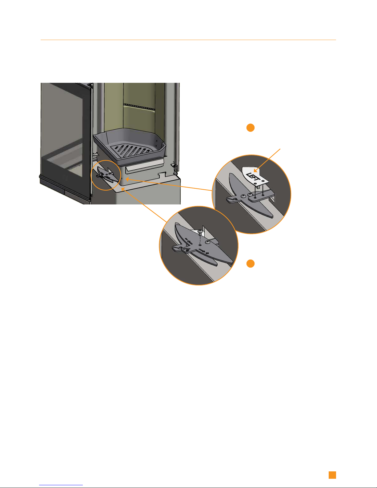
MOUNTING THE UK - BLOCKING AND SCREW
Scan 1008 and 1008-S have been recommented as suitable for use in smoke control areas when burning wood logs and when fitted
with a mechanical stop to prevent that the secondary air valve cannot be closed lower than 868 mm2 .
NOTE: In order to a achieve this, the blocking piece and screw (M5 x 8) must be placed as shown in the pictures, to prevent that the
secondary air valve can be closed completely.
1
2
Remove the secondary air damper
and place the UK-blocking piece
Remount the secondary air
damper on top and replace the
front screw with the longer
UK-screw

14.08.2018
SCAN A/S | Glasvænget 3-9 | DK-5492 Vissenbjerg | www.scan.dk
Edition:
UK 90080500
Product registration number
Quote this number at all enquiries
 Loading...