

1002,1001,1001 BB,1001 WC,1002 WC,1002 BB,1001 BS,1002 BS,1003 Series,1003 WC,1003 BS,1004 Series,1004 BB,1004 WC,1004 BS,1003 BB
SCAN 1002,1001,1001 BB,1001 WC,1002 WC,1002 BB,1001 BS,1002 BS,1003 Series,1003 WC,1003 BS,1004 Series,1004 BB,1004 WC,1004 BS,1003 BB Assembly And Instruction Manual
1001/1002
UK
SCAN
ASSEMBLY AND INSTRUCTION MANUAL SCAN 1001/1002
UK - ASSEMBLY AND INSTRUCTIONS MANUAL
SCAN
1001/1002

SCAN 1001 WC SCAN 1001 BSSCAN 1001 BB
SCAN 1002 WC SCAN 1002 BSSCAN 1002 BB
1001/1002
2
You have purchased a product by one of Europe’s leading manufacturers of
wood-burning stoves, and we are sure that you will have years of pleasure from your
purchase. To make the best possible use of your stove, it is important that you
follow our advice and instructions.
Read through this Assembly and Instruction Manual carefully before you start to
assemble your stove.
UK
SCAN
CONGRATULATIONS
ON YOUR NEW SCAN
BUILT-IN STOVE

3
CONTENTS
¬¬ TECHNICAL DATA 4
Installation 4
Safety 4
The Clean Air Act 1993 and Smoke Control Areas 4
Technical data and dimensions 5
Dimension sketch Scan 1001 6
Dimension sketch Scan 1002 7
Type plate 8
Product registrationumber 8
¬¬ ASSEMBLY 9
Tools needed for mounting of the insert 9
Loose parts 9
Additional accessories 9
Disposal of packaging 9
Load-bearing foundation 9
Floor plate 10
Convection air 10
Existing chimney and pre-fabricated element chimney 10
Connection between built-in stove and steel chimney 10
Requirements for chimney 10
Internal installation in non-flammable material 10
Trims and doors 11
Gasket 11
Distance to furniture 11
Safety distance 11
Building into flammable material with fire wall 12
Operating the door 15
Remove packaging 15
Fitting the flue connection piece 17
Fresh air intake 17
Closed combustion system 17
Mounting of external air supply 18
Fitting without the convection connection pieces 20
Fitting the convection connection pieces 20
Fitting the cassette 21
Mount the insert in the cassette 24
Mounting of the trim 25
Indicator for regulation of air supply 26
Mounting of convection grate 27
Mounting of combustion chamber 28
¬¬ INSTRUCTIONS FOR USE 30
CB-technology (Clean Burning) 30
Baffle plate 30
Primary air 30
Secondary air 30
¬¬ INSTRUCTIONS FOR HEATING 31
Environmentally friendly operation 31
Lighting 31
Using the stove in various weather conditions 31
Continuous operation 32
Warning about over-firing 32
Firing in the spring or autumn 32
The function of the chimney 32
General notes 32
Chimney fire 32
¬¬ HANDLING OF THE FUEL 33
Selecting wood/fuel 33
Preparation 33
Storing 33
Moisture 33
Use of the following as fuel is illegal 33
Calorific value of the wood 33
¬¬ MAINTENANCE 34
Sweeping the chimney and cleaning the stove 34
Checking the stove 34
Servicing 34
Combustion chamber lining 34
Gaskets 34
Painted surfaces 34
Cleaning the glass 35
Removing the baffle plate and the baffle unit 35
Disposal of stove parts 35
¬¬ TROUBLESHOOTING 36
¬¬ WARRANTY 37
Smoke Control Area air supply requirements 38

4
YOU GET THE BEST USE OF
THE STOVE BY USING
A TOP-DOWN
LIGHTING METHOD
SEE
"INSTRUCTIONS FOR HEATING"
PLEASE NOTE!
TECHNICAL DATA
INSTALLATION
¬ The house owner is responsible for ensuring that installation and assembly are in accordance with national and local
building regulations as well as the information provided in this Assembly and Instructions Manual.
¬ When you install any kind of fireplace or stove, you must inform the local building and housing authorities. In addition
you are obliged to have the installation inspected and approved by a local chimney sweep prior to commissioning.
¬ To ensure best-possible functionality and safety for your installation, we advise you to call a professional fitter. Your Scan
dealer will be able to recommend a qualified fitter in your area. For information on Scan Dealers, please go to www.scan.dk.
SAFETY
Any changes made to the product by the dealer, fitter or user could result in the product and safety functions not functioning as
intended. The same applies to the fitting of accessories or extra equipment not supplied by Scan A/S. This could also be the case
if parts that are necessary for the operation and safety of the stove are dismantled or removed.
THE CLEAN AIR ACT 1993 AND SMOKE CONTROL AREAS
Under the Clean Air Act local authorities may declare the whole or part of the district of the authority to be a smoke control area.
It is an offence to emit smoke from a chimney of a building, from a furnace or from any fixed boiler if located in a designated smoke
control area. It is also an offence to acquire an "unauthorized fuel" for use within a smoke control area unless it is used in an "exempt" appliance ("exempted" from the controls which generally apply in the smoke control area).
The Secretary of State for Environment, Food and Rural Affairs has powers under the Act to authorize smokeless fuels or exempt appliances for use in smoke control areas in England. In Scotland and Wales this power rests with Ministers in the devolved
administrations for those countries. Separate legislation, the Clean Air (Northern Ireland) Order 1981, applies in Northern
Ireland. Therefore it is a requirement that fuels burnt or obtained for use in smoke control areas have been "authorized" in Regulations and that appliances used to burn solid fuel in those areas (other than "authorized" fuels) have been exempted by an Order
made and signed by the Secretary of State or Minister in the devolved administrations.
¬ Further information on the requirements of the Clean Air Act can be found here: www.smokecontrol.defra.gov.uk
¬ Your local authority is responsible for implementing the Clean Air Act 1993 including designation and supervision of smoke
control areas and you can contact them for details of Clean Air Act requirements”
¬ The secondary air valve has been modified, so that is does not close completely but has an opening corresponding to the posi-
tion used at the lowest emission test.
¬ You can use any type of wood as fuel.
¬ This stove has been recommended as suitable for use in smoke control areas when burning wood.

5
TECHNICAL DATA AND DIMENSIONS
Scan 1001 – Test in compliance with EN 13229
CO Emission at 13% O
2
0,07 %
CO Emission at 13% O
2
879 mg/Nm
3
Dust @ 13% O
2
12 mg/Nm
3
Nox @ 13% O
2
42 mg/Nm
3
Efficiency 82 %
Energy efficiency index 109,9
Energy efficiency class A+
Nominel output 7 kW
Chimney temperature EN 13229 220 °C
Temperature in flue conn. piece 264 °C
Amount of smoke 7,4 g/sek
Sub-pressure EN 13229 12 Pa
Recommended sub-pressure in
connecting piece
16-18 Pa
Required combustion air supply 19,8 m
3
/h
Fuel Wood
Fuel consumption 2,2 kg/h
Amount of fuel required to light 1,7 kg
Amount of fuel, max. 3 kg
Materials
Steel plate
galvanised sheet
Vermiculite
Chamotte
Robax glass
Surface treatment Senotherm
Max. wood length Scan 1001 50 cm
Max. wood length Scan 1002 65 cm
Weight Scan 1001 ca. 107 kg
Weight Scan 1002 ca. 124 kg
Connecting piece internal diameter 144 mm
Connecting piece external diameter 148 mm
Approval type
Intermittent
fuelling*
Scan 1002 – Test in compliance with EN 13229
CO Emission at 13% O
2
0,07 %
CO Emission at 13% O
2
864 mg/Nm
3
Dust @ 13% O
2
9 mg/Nm
3
Nox @ 13% O
2
91 mg/Nm
3
Efficiency 82 %
Energy efficiency index 109,9
Energy efficiency class A+
Nominel output 8 kW
Chimney temperature EN 13229 208 °C
Temperature in flue conn. piece 250 °C
Amount of smoke 7,9 g/sek
Sub-pressure EN 13229 12 Pa
Recommended sub-pressure in con- 16-18 Pa
Required combustion air supply 22 m
3
/h
Fuel Wood
Fuel consumption 2,3 kg/h
Amount of fuel required to light 1,9 kg
Amount of fuel, max. 4 kg
* Intermittent operation in this context means normal use of a
wood-burning stove. In other words, you should let the fire die
down until only the embers are left before refuelling.
Scan 1001-1002 is produced in accordance with type approval for the product, which also covers the product’s Assembly
and Instruction Manual.
The Declaration of Performance (DoP) is available from www.
scan.dk
688
6
2
3
1
0
5
325
5
6
6
438
107
9
2
650
125
1
3
0
M
i
n
5
9
0
Min
6
7
0
M
i
n
4
5
0
4
8
9
5
6
3
5
7
0
D
A
B
C
6
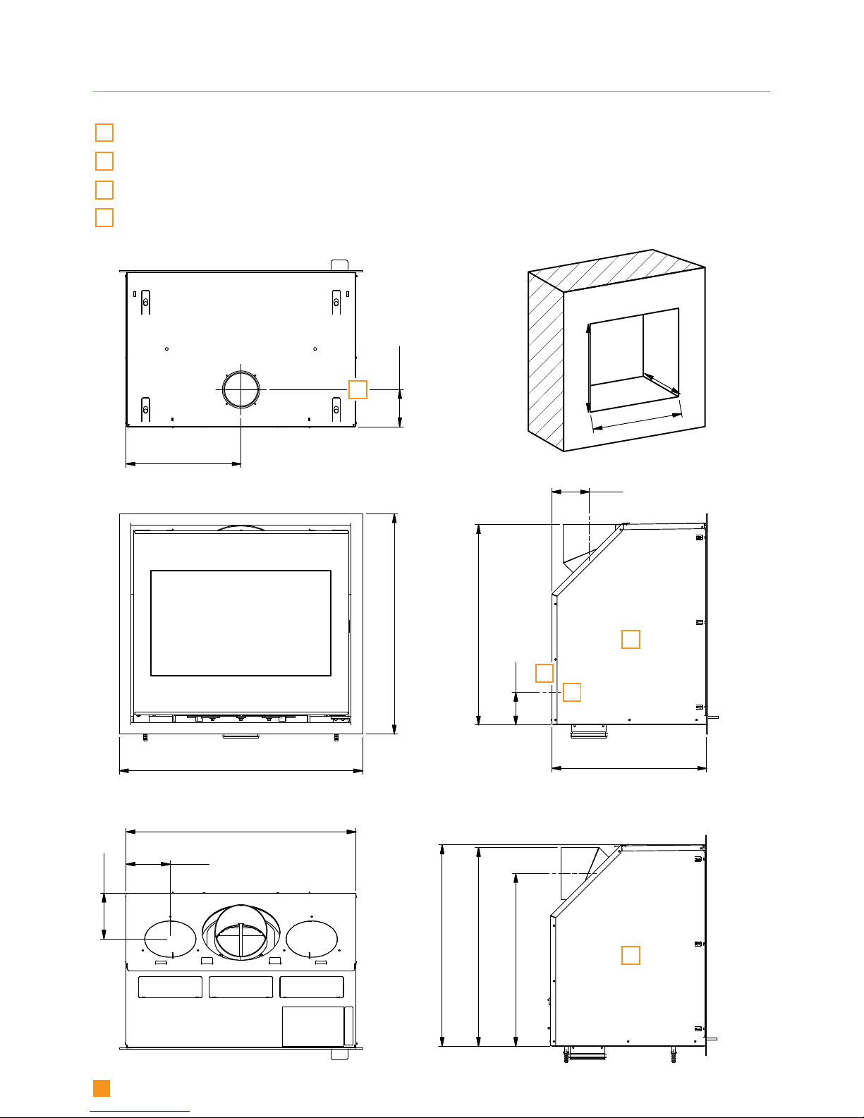
DIMENSION SKETCH SCAN 1001
A
Top outlet
B
Rear outlet
C
Centre external air supply, rear side
D
Centre of external air supply, bottom
All measures are in mm
C

400
1
0
5
838
6
2
3
438
800
200
1
3
0
5
7
0
9
2
4
8
9
5
6
3
M
i
n
5
9
0
M
i
n
4
5
0
M
i
n
8
2
0
5
6
6
D
A
B
C
7
DIMENSION SKETCH SCAN 1002
A
Top outlet
B
Rear outlet
C
Centre external air supply, rear side
D
Centre of external air supply, bottom
All measures are in mm
100100000 100200000
Scan 1001
Insert fired by solid fuel
Standard:
Fuel type:
Operation type:
The appliance can be operated in a shared flue.
Country
EN 13229 EC no. 91001600
Wood
Intermittent
EUR
Norway
Classification
Intermittent
Klasse 2
Certificate/Standard
EN 13229
300-ELAB-1588-NS
Approved by
Teknologisk Institut
Teknologisk Institut
Dust at 13% O2: 12 mg/Nm³
Flue gas temperature: 220°C
Nominal heat output: 7 kW
Efficiency: 82%
Scan A/S DK 5492 Vissenbjerg
Minimum distance to heat insulation:
Side: 25 mm - Back: 100 mm - Top: 800 mm - Bottom: 400 mm
Minimum insulation:
CO emission at 13% O2:
See assembly- and instructions manual
Follow assembly- and instructions manual.
Use only recommended fuels.
Montage- und Bedienungsanleitung beachten.
Verwenden Sie nur empfohlene Brennstoffe.
1000 11-2012
0,07% 879 mg/Nm³
Schweiz
Germany
LRV 11
BStV 1
VKF
300-ELAB-1588-EN
Teknologisk Institut
Teknologisk Institut
Scan 1002
Insert fired by solid fuel
Standard:
Fuel type:
Operation type:
The appliance can be operated in a shared flue.
Country
EN 13229 EC no. 91002600
Wood
Intermittent
EUR
Norway
Classification
Intermittent
Klasse 2
Certificate/Standard
EN 13229
300-ELAB-1664-NS
Approved by
Teknologisk Institut
Teknologisk Institut
Dust at 13% O2: 9 mg/Nm³
Flue gas temperature: 208°C
Nominal heat output: 8 kW
Efficiency: 82%
Scan A/S DK 5492 Vissenbjerg
Minimum distance to heat insulation:
Side: 25 mm - Back: 100 mm - Top: 800 mm - Bottom: 450 mm
Minimum insulation:
CO emission at 13% O2:
See assembly- and instructions manual
Follow assembly- and instructions manual.
Use only recommended fuels.
Montage- und Bedienungsanleitung beachten.
Verwenden Sie nur empfohlene Brennstoffe.
1000 11-2012
0,07% 864 mg/Nm³
Schweiz
Germany
LRV 11
BStV 1
VKF
300-ELAB-1624-EN
Teknologisk Institut
Teknologisk Institut
A
8
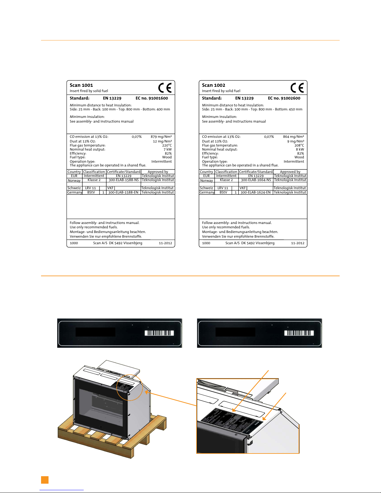
Type plate Scan 1001 Type plate Scan 1002
Product registration number Scan 1001 Product registration number Scan 1002
Product registration number
Type plates
PRODUCT REGISTRATIONUMBER
All Scan built-in stoves are provided with a product registration number. Please make a note of this number at the rear page of
this manual; you will always need to quote it when contacting your dealer or Scan A/S.
TYPE PLATE
All Scan built-in stoves are fitted with a type plate that specifies the approval standards and the distance to flammable materials.
9
ASSEMBLY
TOOLS NEEDED FOR MOUNTING OF THE INSERT
¬ Spirit level ¬ Cutting nippers
¬ Cross tip screwdriver ¬ Flat head screwdriver
¬ Ø10 wall drill ¬ Open-end spanner
LOOSE PARTS
The trim is delivered on the wood pallet together with the insert.
In the insert’s combustion chamber you will find the following loose parts
¬ Baffle plates ¬ Burn chamber plates (side and rear)
¬ Bricks for the bottom of the burn chamber ¬ Log guard
¬ Glove
¬ Bag containing loose parts:
4 x self-tapping screws 4.2 x 6.5 mm 8 x 3 mm black self-adhesive gasket (2 m)
(for fastening the sleeve Ø100 mm) (Ø100 mm sleeve, connecting piece and cassette)
4 x rawlplugs10 x 50 mm (for fastening the cassette) 4 x torx screws M6 x 50 (for fastening the cassette)
4 x discs Ø6.5 / Ø16 x 1.1 (for fastening the cassette) 2 pins for the lower smoke deflector plate
Indicator for the regulation of the air supply Ø100 mm sleeve with flange
Torx key 5 mm Screw M5x6 (United Kingdom)
ADDITIONAL ACCESSORIES
¬ Convection adaptors Ø149 mm (see page 20)
¬ Convection grates (See page 26)
DISPOSAL OF PACKAGING
Your Scan built-in stove may come supplied with the following packaging:
Wood packaging
The wood packaging can be reused and after final use can be incinerated as a CO2 neutral
product or sent for recycling.
Polystyrene top Send for recycling or waste disposal.
Foam Send for recycling or waste disposal.
Plastic bags Send for recycling or waste disposal.
Stretch/plastic film Send for recycling or waste disposal.
LOAD-BEARING FOUNDATION
All items in our product range come under the category of lightweight fireplaces and stoves and do not normally require any
reinforcement of the beam structure. They can be positioned on ordinary beams/floor.
You should of course make sure that the foundation on which the stove is positioned can indeed support the weight of the stove
and, where applicable, a steel chimney, if you have opted for this solution.

10
FLOOR PLATE
If you are placing the stove on a flammable floor, you must comply with the national and local regulations on the size of any
non-flammable subsurface required to cover the floor around the stove.
Your local Scan dealer can advise you on regulations concerning protection of flammable materials in the vicinity of your stove.
The floor plate’s function is to protect the floor and flammable material against any sparks that may occur.
CONVECTION AIR
The covering must contain holes for convection air. Convection means that there is an air circulation ensuring that the heat is
equally distributed in the room. It is important that the demands concerning convection areas are observed.
¬ Min. area for ingoing convection air: 350 cm
2
¬ Min. area for outgoing convection air: 500 cm
2
If there is not enough convection air, the covering may be damaged.
Convection air grids are available as an accessory.
EXISTING CHIMNEY AND PRE-FABRICATED ELEMENT CHIMNEY
If you intend to connect your stove to an existing chimney, it makes sense to contact an authorised Scan dealer, or a local chimney sweep, for advice. These experts will also let you know if your chimney needs renovating.
¬ When connecting a pre-fabricated element chimney, follow the manufacturer’s connection instructions for the
relevant chimney type.
CONNECTION BETWEEN BUILT-IN STOVE AND STEEL CHIMNEY
Your Scan dealer, or local chimney sweep, can advise you on choosing a make and type of steel chimney. This ensures that the
chimney will match your wood-burning stove.
REQUIREMENTS FOR CHIMNEY
The chimney must have a diameter of min. 148 mm and be labelled T400 and G for soot testing. The length must be min. 4,5
metres.
If you opt to connect the bulit-in stove with an elbow pipe, you should use a curved elbow, as this gives a better draught.
If you connect the stove with a sharp elbow pipe, the cleansing lid must be placed in the vertical part so that the
horizontal part can be cleaned through here.
The requirements to the chimney and the flue pipe in terms of safety distances must be met.
¬ Choosing the wrong length or diameter of steel chimney could impair functionality.
¬ Always comply exactly with the instructions provided by the steel chimney supplier.
INTERNAL INSTALLATION IN NON-FLAMMABLE MATERIAL
When building or fitting into structures that do not contain flammable materials, a minimum distance of 10 mm must be maintained between the brickwork and the convection hood. This is to prevent cracks in the brickwork caused by the expansion of the
metal while the stove is heating.

11
TRIMS AND DOORS
Trims and doors are fitted when the surfaces of the surround have been treated.
GASKET
Gasket 0,75 m is mounted on the inside of the cassette as shown.
DISTANCE TO FURNITURE
Distance to furniture from glass: Scan 1001: 1300 mm. / Scan 1002: 1400 mm.
You should however assess whether furniture or other items might become excessively dry due to being too close to the stove.
The stove is NOT to be built into flammable materials without the use of a fire wall!
SAFETY DISTANCE
European, national and local regulations concerning safety distances for wood-burning stoves must be complied with.
Gasket

4
0
0
6
0
0
8
5
0
4
2
0
1
0
0
25 25
450
250
1
3
0
0
8
0
0
Min. 350 cm
2
Min. 500 cm
2
* *
*
450
Scan 1001: 1300 / Scan 1002: 1400*
12
BUILDING INTO FLAMMABLE MATERIAL WITH FIRE WALL
Cavities are not to be
filled out with
insulation material!
Installation with an un-insulated elbow pipe
Lower
convection
opening
Upper
convection
opening
These cover plates must be
removed when installing into
flammable material protected
by insulation
Flammable materials
Floor plate
Distance to furniture from glass
Floor
Ceiling
Flammable material
Fire wall, e.g. 50 mm Jøtul Firewall, 110 mm brick
or other material with corresponding fireproof and
insulating abilities
All distances are in mm.
All distances are minimum distances
* Applies for all installations
Chimney
 Loading...