

Scan 1002
ASSEMBLY- AND INSTRUCTIONS MANUAL
SCAN A/S - DK-5492 VISSENBJERG
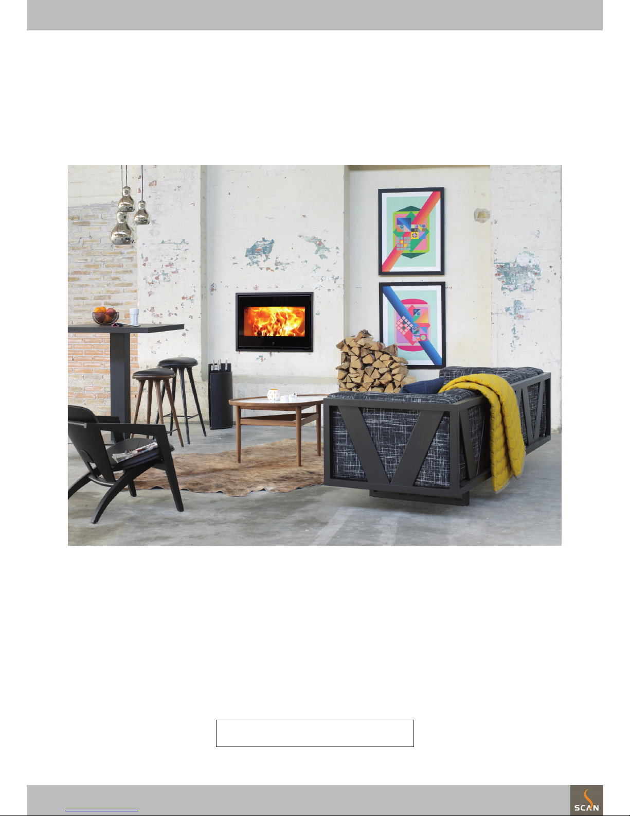
Congratulations on your new Scan built-in stove
You have purchased a product by one of Europe’s leading manufacturer’s of wood-burning stoves, and we are sure that you will have years of pleasure
with your purchase.
To make the best possible use of your built- in stove, it is important that you follow our advice and instructions.
Please read this Assembly- and instructions manual before you start to assemble your built-in stove.
Product registration number
Please indicate the product registration number at any enquiry
GB

CONTENTS
2
Table of contents
Technical data ............................................................................................................. 3
Scan 1002 versions
Installation
Safety
Technical data and dimensions
Dimension sketch1
Product registration number
Type plate
Assembly ...................................................................................................................... 6
Operating the door
Loose parts
Additional accessories
Remove packaging
Load bearing foundation
Floor plate
Installation in flammable material protected by insulation
Internal installation in non-flammable material
Distance to furniture
Trim and door
Gasket
Existing chimney and pre-fabricated element chimney
Connection between stove and steel chimney
Requirements for chimney
Installation in flammable material protected by insulation
Defra’s air supply requirements
Connecting piece
Fitting the cassette
Mount the insert in the cassette
Combudtion chamber
Indicator for control of air supply
Mounting of the trim
Fresh air intake
Closed combustion system
Accessories .............................................................................................................. 22
Fitting the convection adaptors
Instruction for use ................................................................................................. 23
CB technique
Baffle plates
Primary air
Secondary air
Instructions for heating ....................................................................................... 24
Lighting
Handling fuel
Maintenance ............................................................................................................. 26
Troubleshooting ...................................................................................................... 28
Installation
The house owner is responsible for ensuring that all necessary national and local safety measures are observed during installation and
fitting and also responsible for observing the fitting and operating
instructions detailed in this manual.
When you install any kind of fireplace or stove, you must inform the
local authorities. You are also responsible for calling in a chimney
sweep to inspect and authorize the installation.
To ensure best-possible functionality and safety for your installation, we advise you to call a professional fitter. Our Scan Dealer will
be able to recommend a qualified fitter in your area. For information
on Scan Dealers, please go to scan.dk.
Technical data and dimensions
Materials: .............................. Steel plate, galvanised sheet, Vermiculite,
Chamotte, Robax glass
Surface treatment: .......................................................................... Senotherm
Max. wood length: ..................................................................................... 65 cm
Weight Scan 1002: ............................................................................ ca. 124 kg
Connecting piece internal diameter: .............................................. 144 mm
Connecting piece external diameter: ............................... ............. 148 mm
Approval type: ................................................................ Intermittent fuelling
Intermittent fuelling means normal use of a woodstove. In other
words, you should let the fire die down until only the embers are left,
before refuelling.
The Scan 1002 was build in compliance with the homologized product
type specified in the Assembly- and Instructions Manual provided
with the product.
The DoP declaration of conformity is available from scan.dk
Test in compliance with EN 13229
Scan 1002 is available in the following versions:
Scan 1002 BB
(black glass decor, black trim, and black glass handle)
Scan 1002 WC
(white glass decor, matt chrome trim, and clear glass handle)
Scan 1002 BS
(black steel door, black trim and black glass handle)
TECHNICAL DATA
3
Safety
Any changes made to the product by the dealer, installer or user
could result in the product and safety functions not functioning as
intended. The same applies to the fitting of accessories or extra
equipment not supplied by Scan A/S. This could also be the case if
parts that are necessary for the operation and safety of the stove
are dismantled or removed.
Scan 1002 Technical data Unit
CO Emission at 13% O
2
0,07 %
CO Emission at 13% O
2
864 mg/Nm
3
Dust @ 13% O
2
9 mg/Nm
3
Nox @ 13% O
2
91 mg/Nm
3
Efficiency 82 %
Nominel output 8 kW
Chimney temperature EN 13229 208 °C
Amount of smoke 7,9 g/sek
Sub-pressure EN 13229 12 Pa
Recommended sub-pressure in connecting piece 16 - 18 Pa
Required combustion air supply 22 Nm3/h
Fuel Wood
Fuel consumption 2,3 kg/h
Amount of fuel 1,9 kg
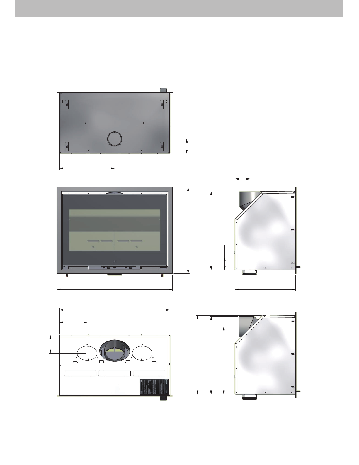
Dimension sketch
Connecting piece - top outlet
Connecting piece - rear outlet
* Centre external air supply, rear side
** Centre of external air supply, bottom
TECHNICAL DATA
4
400
105**
838
623
566
438
800
200
130
107
570
92*
489
563

A
product registration
number
A
Type plates
Type plates
All Scan wood-burning stoves are fitted with a type plate, that specifies the approval standards and the distance to flammable materials.
Scan 1002
Insert fired by solid fuel
Standard:
Fuel type:
Operation type:
The appliance can be operated in a shared flue.
Country
EN 13229 EC no. 91002600
Wood
Intermittent
EUR
Norway
Classification
Intermittent
Klasse 2
Certificate/Standard
EN 13229
300-ELAB-1664-NS
Approved by
Teknologisk Institut
Teknologisk Institut
Dust at 13% O2: 9 mg/Nm³
Flue gas temperature: 208°C
Nominal heat output: 8 kW
Efficiency: 82%
Scan A/S DK 5492 Vissenbjerg
Minimum distance to heat insulation:
Side: 25 mm - Back: 100 mm - Top: 800 mm - Bottom: 450 mm
Minimum insulation:
CO emission at 13% O2:
See assembly- and instructions manual
Follow assembly- and instructions manual.
Use only recommended fuels.
Montage- und Bedienungsanleitung beachten.
Verwenden Sie nur empfohlene Brennstoffe.
1000 11-2012
0,07% 864 mg/Nm³
Schweiz
Germany
LRV 11
BStV 1
VKF
300-ELAB-1624-EN
Teknologisk Institut
Teknologisk Institut
100200000
Product registration number
All wood-burning stoves are provided with a product registration
number.
Please make a note of this number at the front page. You will always
have to state the number if you contact your dealer or Scan A/S.
TECHNICAL DATA
5
Additional accessories
• Convection adaptors Ø149 mm (accessory), see page 21
Loose parts
The trim is delivered on the wood pallet together with the insert.
In the insert’s combustion chamber you will find the following loose
parts:
• Glove
• Baffle plates
• Burn chamber plates (side and rear)
• Bricks for the bottom of the burn chamber
• Log guard
• Seal
• Bag containing loose parts:
• 4 x self-tapping screws 4.2 x 6.5 mm
(for fastening the sleeve Ø100 mm)
• 8 x 3 mm black self-adhesive gasket (2 m)
(Ø100 mm sleeve, connecting piece and cassette)
• 4 x rawlplugs10 x 50 mm (for fastening the cassette)
• 4 x torx screws M6 x 50 (for fastening the cassette)
• 4 x discs Ø6.5 / Ø16 x 1.1 (for fastening the cassette)
• 2 pins for the lower smoke deflector plate
• Indicator for the regulation of the air supply
• Ø100 mm sleeve with flange
• Torx key 5 mm
• Screw M5x6 (United Kingdom)
ASSEMBLY
6
Operating the door
Push down the handle and the door will open.
The door should be banged shut, as on a car. Grip the handle (hold in a
horizontal position) and bang the door shut.
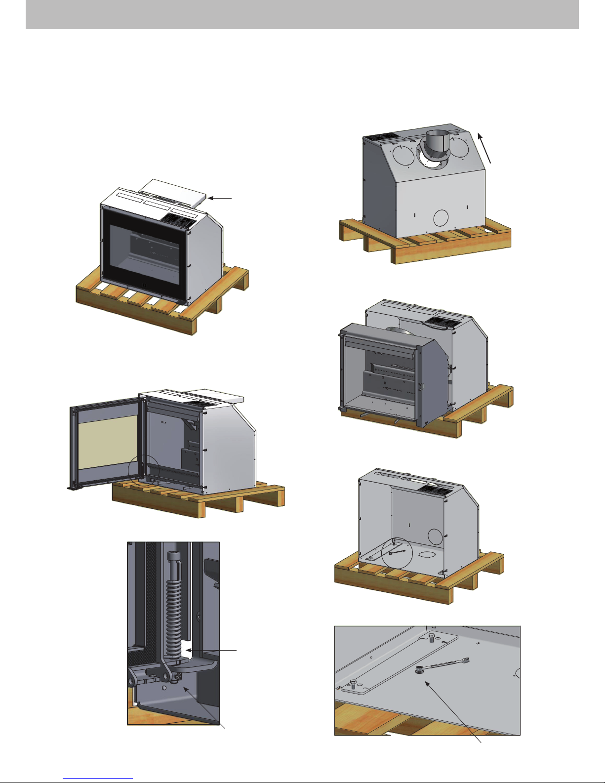
Dismount the connecting piece.
Loosen (not dismount) the flange nuts holding the connecting piece
inside the stove. Push the connecting piece in the direction of the
arrow and remove it.
Remove the two screws securing the cassette to the pallet.
Screws to be removed
C
Pull the insert out of the cassette.
ASSEMBLY
7
C
Remove packaging
Check that the stove is not damaged before installing it.
Scan 1002 is delivered secured to the pallet. It is recommended that
you remove the door and take all loose parts out of the combustion
chamber before unscrewing the stove from the pallet; this will facilitate the mounting of the insert.
Dismount the combustion air box. This box is only needed, if the insert
is to be connected with external air supply, see page 19.
B
To remove the door:
Loosen the pointed screw, remove the screw and the spring and lift
off the door
Combustion air box
B
Pointed screw
Screw and
spring
ASSEMBLY8
Existing chimney and pre-fabricated element
chimney
If you intend to connect your stove to an existing chimney, it makes
sense to contact an authorised Scan dealer, or a local chimney sweep
for advice. These experts will also let you know if your flue needs
renovating.
When connecting a pre-fabricated element chimney, follow the
manufacturer’s connection instructions for the relevant chimney
type.
Connection between stove and steel chimney
Your Scan dealer, or local chimney sweep, can advise you on choosing
a make and type of steel chimney. This ensures that the chimney
will match your wood-burning stove. As a general rule, the length of
the flue should not be less than 4,5 m measured from the top of the
wood-burning stove.
Some weather or installation conditions might require another
length.
Choosing the wrong length or diameter of steel chimney could impair
functionality.
Always observe the chimney vendor‘s instructions precisely.
Requirements for chimney
The chimney must be labelled T400 and G for soot testing.
If the chimney is installed as an extension of the stove and has a
length of at least 4.5 metres, a 6" chimney can be used.
If the insert is connected with an elbow pipe or other bends on the
chimney, we recommend a 7” chimney.
If you connect the stove with an elbow pipe, you should use a curved
elbow, as this gives a better draught.
If you are connecting your stove using a sharp elbow bend, the cleanout door should be in the vertical section, such that the horizontal
part can be cleaned through it.
National and local regulations for chimney ducts in flammable materials must be respected too.
Before installing the stove
Load bearing underlay
You must ensure that the underlay on which the stove is to be installed is a supporting underlay that is strong enough to support the
weight of the stove and, if necessary, the chimney and a surround. If
you are unsure about the strength of the base, contact a specialist
before the installation.
Floor plate
If you are setting up the stove on a flammable floor, observe national
and local regulations on the size of the non-flammable underlay that
covers the floor around the stove.
Your local Scan dealer can advise you on regulations concerning flammable materials in the vicinity of your stove.
The idea behind the floor plate is that it protects the floor and flammable material against sparks.
The floor plate can be made of steel or glass, and the stove can be set
up on brick, natural stone or similar materials.
nstallation in flammable material protected by
insulation
All installations where there is no existing fireplace opening must be
ventilated.
Structure/surround to ceiling:
Holes must be made in the structure/surround for convection air.
Convection means that air circulation occurs, so that the heat is
distributed more evenly around the room.
You must ensure that the requirements for convection areas are met.
Area for convection air in: 350 cm2
Area for convection air out: 500 cm2
If insufficient convection is created, the structure/surround may be
damaged.
Open the cassette in the top plate (see page 11).
Place an air baffle made from non-flammable material (such as Jøtul
Firewall) in direct connection with the upper convection opening. It
is recommended that you tilt the plate at an angle of 20–30° (see
page 10).
Open structure/surround:
Ved indmuring/montering i en konstruktion/omramning som er åben i
toppen, kan konvektionshuller udelades. Dog skal man være opmærksom på at der ikke må lægges en topplade på konstruktionen, se side
11.
Open the cassette in the top plate (see page 11).
Internal installation in non-flammable material
When building or fitting into structures that do not contain flammable materials, a minimum distance of 10 mm must be maintained
between the brickwork and the convection hood. This is to prevent
cracks in the brickwork caused by the expansion of the metal while
the stove is heating.
Distance to furniture: 1400 mm
But please check to avoid furniture or other furnishings being dried
out due to being too close to the stove.
Trims and doors
Trims and doors are fitted when the surfaces of the surround have
been treated.
Trim, see page 19.
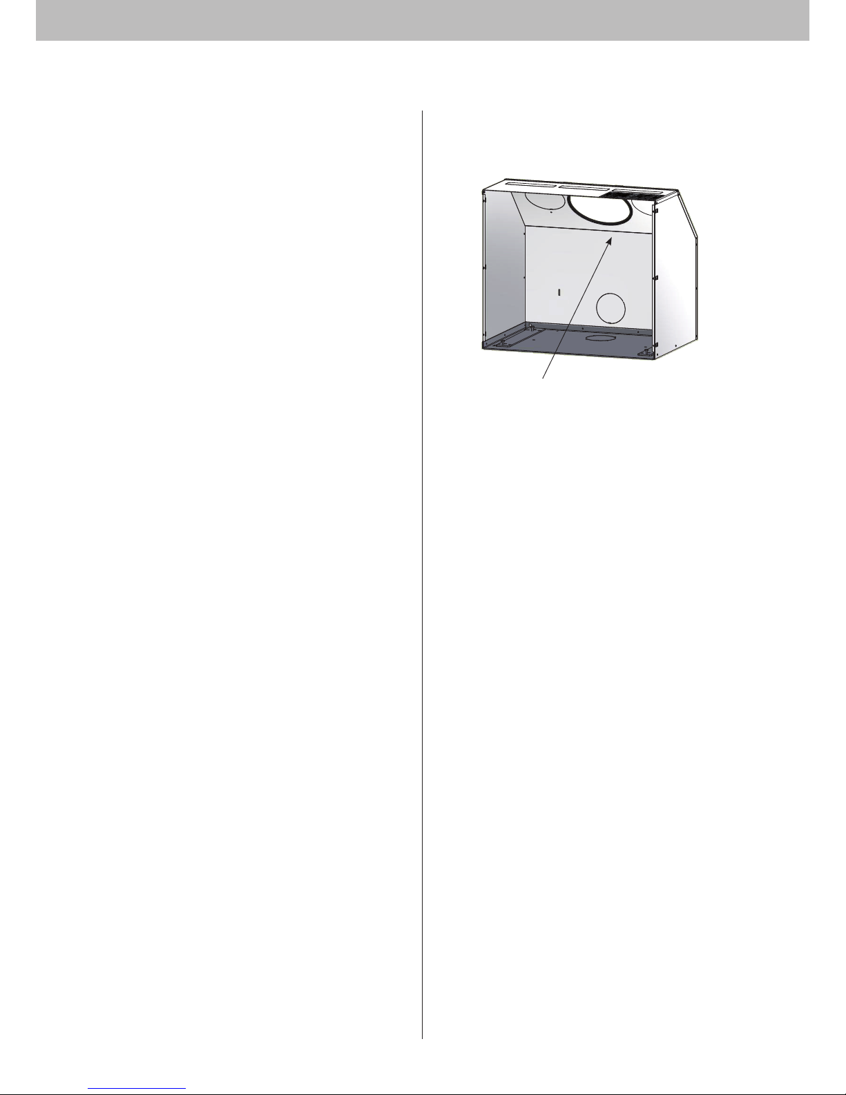
Gasket
Gasket
Gasket 0,75 m is mounted on the inside of the cassette as shown.
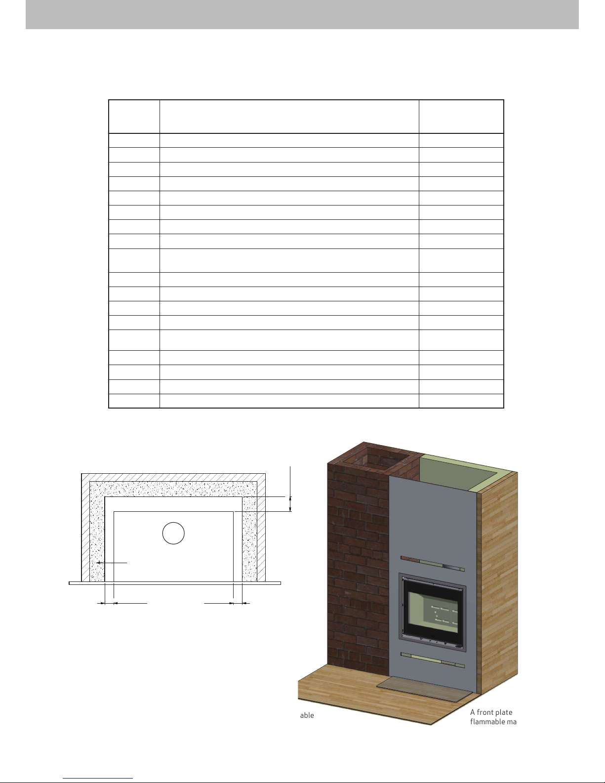
Flammable materials
If the floor contains flammable
materials the height above the floor
must be at least 450 mm.
A front plate of nonflammable material.
ASSEMBLY 9
Scan 1002
Minimum mea-
surements
1A Building height over flammable floor 450 mm
1B Free height over horizontal flue pipe to insulation material, 600 mm
1C Free height over insert to insulation material, 800 mm
1D Distance to flammable side wall in front of insert 500 mm
1E Distance to non-flammable (side wall) in front of insert 250 mm
1F Distance to insulation material, side 25 mm
1G Distance to insulation material, rear 100 mm
Distance to furniture 1400 mm
Distance from convection opening above stove to insulation
material
400 mm
Convection air
1H Lower convection opening 350 cm
2
1I Upper convection opening 500 cm
2
Insulation material
Porous concrete 100 mm
Rockwool Brandbatts with smooth heat-resistant surface 50 mm
Jøtul Fire Wall JGFW-5 50 mm
Data to use when building in the insert, see fig. 1
Bræ
ndbart materiale
Bræ
ndbart
materiale
Brændbart materiale
Isolationsmateriale
Insulation material
Scan 1002
1F 1F
1G
Flammable mate-
rials
Flammable materials
Flammable materials

ASSEMBLY10
1D - 1E
1B
1G
1F
1A
1C
Insulationmaterial
Flammablematerials
1H
1I
These cover
plates must
be removed
when installing
into flammable material
protected by
insulation.
Installation in flammable material protected by insulation
Figur 1.
Konvektions-
åbning
Konvektions-
åbning
Min. 400
1C
Cavities are
not to be filled
out with insulation material!
Insulation
material
Flammable
materials
Air baffle
Structure/surround to ceiling:
Upper convec-
tion opening
Lower convec-
tion opening

ASSEMBLY 11
OBS! If you have bought convection adaptors for the insert, go to
page 21 Then continue with the mounting as described below.
If the stove is to be connected with an external air supply, see page
19.
To dismount the cover plates for the convection air, use a slotted
screwdriver as illustrated below. Tilt the screwdriver downwards and
loosen the cover plate.
Cassette without cover plates in the top plate.
Min. 500
Min. 1400
Flammable materialsFlammable materials
convection opening
Flammable materials
Insulation material
Open structure/surround:

ASSEMBLY12
Smoke Control Area air supply requirements
The M5x6 screw is fitted to ensure that the stove's secondary air
control is fixed to 33% open in its minimum position to minimise
smoke emission in Smoke Control Areas. It is an offence to burn
wood in an appliance within a smoke control area that has not been
modified in this way.
Screw M5x6
Refuelling on to a low fire bed
If there is insufficient burning material in the firebed to light a new
fuel charge, excessive smoke emission can occur. Refuelling must
be carried out onto a sufficient quantity of glowing embers and ash
that the new fuel charge will ignite in a reasonable period. If there
are too few embers in the fire bed, add suitable kindling to prevent
excessive smoke
Fuel overloading
The maximum amount of fuel specified in this manual should not be
exceeded, overloading can cause excess smoke.
Operation with door left open
Operation with the door open can cause excess smoke. The appliance must not be operated with the appliance door left open except
as directed in the instructions.
Dampers left open
Operation with the air controls or appliance dampers open can
cause excess smoke. The appliance must not be operated with air
controls, appliance dampers or door left open except as directed in
the instructions.
The Clean Air Act 1993 and Smoke Control Areas
Under the Clean Air Act local authorities may declare the whole or
part of the district of the authority to be a smoke control area. It
is an offence to emit smoke from a chimney of a building, from a
furnace or from any fixed boiler if located in a designated smoke
control area. It is also an offence to acquire an "unauthorised fuel"
for use within a smoke control area unless it is used in an "exempt"
appliance ("exempted" from the controls which generally apply in the
smoke control area).
In England appliances are exempted by publication on a list by the
Secretary of State in accordance with changes made to sections 20
and 21 of the Clean Air Act 1993 by section 15 of the Deregulation
Act 2015. Similarly in Scotland appliances are exempted by publication on a list by Scottish Ministers under section 50 of the
Regulatory Reform (Scotland) Act 2014.
In Wales and Northern Ireland these are authorised by regulations
made by Welsh Ministers and by the Department of the Environment
respectively.
Further information on the requirements of the Clean Air Act can be
found here: https://www.gov.uk/smoke-control-area-rules
Your local authority is responsible for implementing the Clean Air
Act 1993 including designation and supervision of smoke control
areas and you can contact them for details of Clean Air Act requirements”
The Scan 1002 BB//WC/BS have been recommended as suitable for
use in smoke control areas when burning wood logs with a modification to the air valve so that it will not close beyond the 33% open
position. See page 25 for useable wood types.
Important!
Iinstalling of the screw for secondary air
control with open position.

ASSEMBLY 13
The adjustment points
in the four corners of
the cassette must be
flush with the front of
the surround.
E
E
D
D
Place the cassette in the hole/surround.
Fitting the cassetteConnecting piece
The insert is prepared for a top flue outlet from the factory, but the
connection piece can be turned around for a rear outlet.
Mount the connecting piece on the insert, after it has been placed in
the cassette.
4 x flange nuts M6
Mount the gasket 3 x 8 mm at the edge of the flange of the connecting
piece. Fasten the connecting piece with the flanged nuts.
Gasket

ASSEMBLY14
To secure the cassette, pre-drill the 4 holes with a 10 mm drill bit.
F
F
To ensure that the cassette is level, you can adjust the adjustment
screws with an open-end spanner.
G
G

ASSEMBLY 15
The top plate of the cassette can be dismounted, after the cassette
has been fastened. This can help facilitating the mounting of the
insert.
Top plate
of the cassette
Dismount two screws in the cassette.
I
I
4 x Rawl plugs 10 x 50
4 x Washers Ø 8 / Ø 16 x 1.1
4 x Torx screws 6 x 50
Mount the rawl plugs, screws and discs. Make sure that the cassette
is level before fastening it. In order to fasten the insert, you can use
the delivered torx key that you will find in the bag in the combustion
chamber.
H
H

ASSEMBLY16
Remove the top plate of the cassette.
Mount the insert in the cassette.
The stove’s pivot pins must fit snugly in the holes in the cassette so
that the stove is secured tightly.
Grip holes for pivot
pins.
Pivot pins on the insert
Insert seen from the side.
Bottom of the cassette.
K
J
J
K

ASSEMBLY 17
Place the upper baffle plate in the top of the stove. It is important
that the plate is placed correctly, see below.
Combustion chamber
Upper baffle plate
In order for the insert to be mounted correctly, it must ”fall down” into
the grip holes of the cassette, so that the insert stands on the bottom
of the cassette.
The bottom of
the cassette
supports the
insert.
L
L
M
M

ASSEMBLY18
Place the bottom stones with the inclined edge turning to the rear
and downwards.
Place the log guard against the front of the insert.
The rear burn chamber plates must be mounted so that the holes of
the plates are placed precisely over the tertiary holes of the insert.
Mount the lower baffle plate. The baffle plate must be supported by
the rear plates. Mount the pins and put the plate in place.
Note that the baffle plates are made of porous, ceramic material, and can break. Exercise care when working.
Mount the rear plates. The side plates keep the rear plates in place,
so that these do not fall over.
Mount the left burn chamber plate.
Mount the right burn chamber plate.

ASSEMBLY 19
Indicator for regulation of air supply
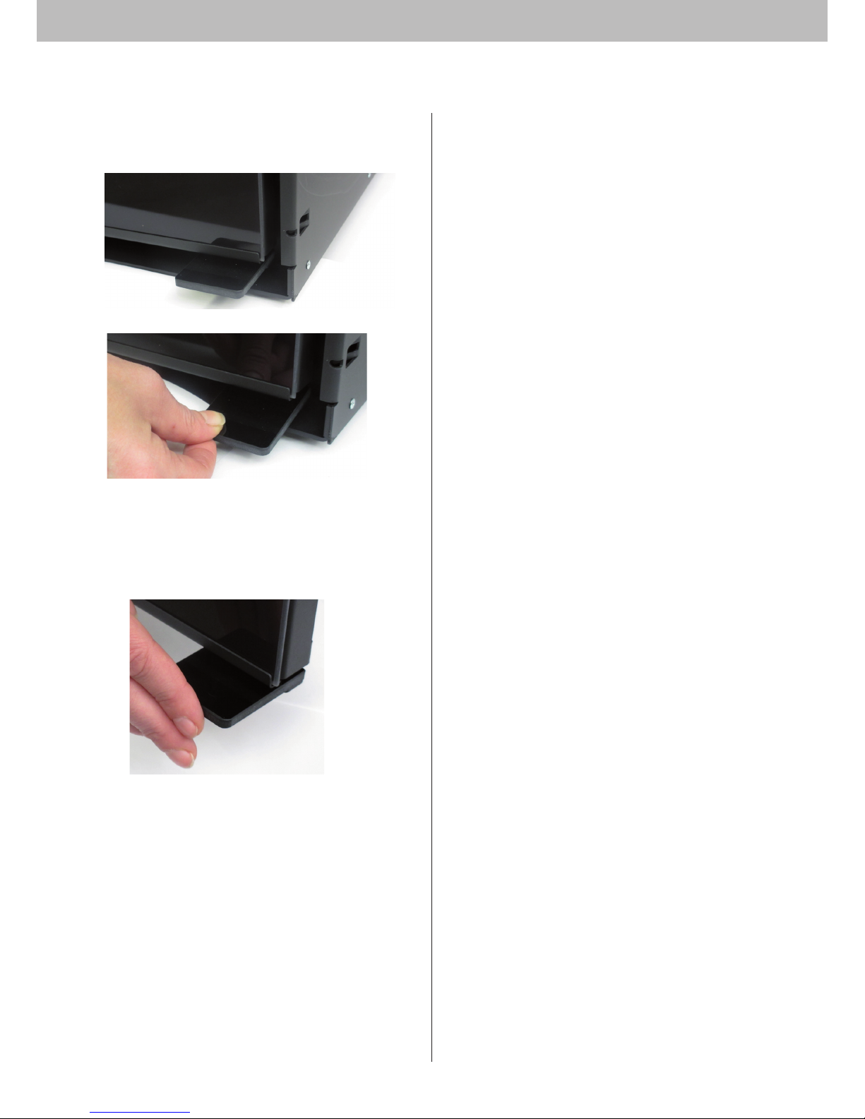
The indicator for regulation of air supply is delivered separately. The indicator can be mounted on the trim as shown below.
Fold the indicator on the middle and remove carefully the foil.
Remove carefully the tape.
1
2
3
4
5
6
7
Place the centre of the indicator on the centre of the trim.
Repeat on the other side.
Stroke a finger over the stickers to ensure that they are fixed
correctly.
387

ASSEMBLY20
Mounting of the trim
We recommend that you do not mount the trim, until the insert has
been approved by the chimney sweep, as he may demand to see the
type plate which is situated on the top plate of the cassette (to dismount the top plate, see page 14).
Mount the guide pins of the trim into the locking devices of the cassette.
Mounting of external air supply
To dismount the cover plates for the Ø100 mm sleeve, use an ordinary
screwdriver as shown below. Tilt the screwdriver and loosen the cover
plates.
External combustion
air on the bottom of
the cassette
External air
supply on the
rear of the cassette
Fresh air intake
In a well-insulated house, the air used up by the burning process has
to be replaced. This particularly applies to houses with mechanical
ventilation. There are different ways of making sure that an air
exchange takes place. The most important thing is to ensure that
there is a supply of air to the room where the wood stove is located.
The external wall vent must be located as close to the wood stove as
possible, and you must be able to close it when you are not using the
wood stove.
National and local building regulations must be followed with regard
to the connection of fresh-air intake.
Closed combustion system
You should use the closed combustion system for the wood-burning
stove if you live in a newly-built, airtight home. Outside air for combustion is connected through a ventilation pipe via the wall or floor.
It must be possible to shut off the ventilation pipe with a valve, when
the stove is not in use.
• Minimum Ø100 mm ventilation pipe, maximum length: 6 m with
a maximum of 3 bends.
Mounting of external air supply on the rear of the cassette
Mount the Ø100 sleeve.
Hitch the combustion air box on the rear plate of the cassette. This
box must always be mounted when connecting the insert with external air supply
4 x self-tapping screws 4.2 x 6.5 mm
Combustion
air box
C
Guide pins
Locking devices

ASSEMBLY
21
Mounting of the external air supply through the bottom of the cassette
Hitch the combustion air box on the rear plate of the cassette. This
box must always be mounted when connecting the insert with external air supply
Mount the Ø100 sleeve.
Combustion
air box
4 x self-tapping screws 4.2 x 6.5 mm
Mount 0.5 m gasket round the flange of the sleeve Ø 100 mm.
N
N
Turn the insert over and remove the cover plate at the bottom.
Mount the insert in the cassette (see page 14).
Cover plate
Ø100 sleeve

ACCESSORIES22
Fitting the convection connection pieces
Convection connection pieces Ø149 mm
To dismount the cover plates for the convection adaptors, use an
ordinary screwdriver as shown below. Tilt the screwdriver and loosen
the cover plates.
Fastening points
6 x Allen screws M4x10
6 x Flange nuts M4
See page 12 for how to fit and tighten the cassette.
When the cassette has been tightened, fit the convection connection
pieces. Fit these and tighten them through the hole for the flue connection piece.
Cassette without cover plates
O
O
P
P

INSTRUCTION FOR USE
23
CB-technique (Clean Burning)
The wood-burning stove is equipped with CB technology. In order
to ensure an optimal combustion of released gases under the incineration process, air will pass through a specially developed canal
system. The heated air is led into the combustion chamber through
the small holes at the rear of the burn chamber. This airflow is driven
by the combustion rate and thus cannot be regulated.
Baffle plates
The baffle plates are located in the upper part of the combustion
chamber. The plates hold back smoke, making sure it stays inside
the combustion chamber for a longer time before escaping through
the chimney. This reduces the smoke gas temperature as the gases
have more time to dissipate heat to the wood-burning stove. The
baffle plates must be removed for sweeping; see „Maintaining your
wood-burning stove“. Note that the baffle plates are made of porous,
ceramic material, and can break. Exercise care when working. The
baffle plates are subject to wear and tear, and are not covered by
the warranty.
0% - 100%
Adjustment of air supply,
primary and secondary damper
Primary air
The primary air regulation mechanism is used for lighting the fire, or
to boost the burning process when you put wood on. The primary air
vent can be 0 - 50% open if you use hard wood fuel such as oak and
beech. You can close the primary air vent if you use soft wood such
as birch or pine for fuel.
Settings for normal load: 0 - 50%
Secondary air
Secondary air is pre-heated and fed indirectly to the fire. At the
same time, the secondary airflow cleans the glass pane to avoid soot
build-up. If you over-restrict the secondary airflow, soot can build up
on the glass pane. The secondary airflow determines the heat output
from your wood stove.
Settings for normal load: 40 - 70%
Primary airCB-technique
0% - 100%
Primary air Secondary air

INSTRUCTIONS FOR HEATING24
Environmentally-Friendly Heating
Avoid restricting your wood-burning stove to an extent where no
flames are visible during the degasifying period, as this leads to
particularly inefficient heating. The gases released by the wood do
not burn due to the low temperature in the combustion chamber. Part
of the gas condenses in the wood-burning stove and flue system as
soot, and this could lead to your chimney catching fire. The smoke
that exits the chimney is bad for the environment and has an unpleasant smell.
Lighting
We recommend the use of fire starters, or similar products, which are
available from your Scan dealer. Using fire starters helps to light the
wood quicker, and keeps the burning process clean.
Never use liquid lighting fuels!e!
"Top down"
4 pieces of wood approx. 25 cm long with a weight of approx. 0.6 –
0.8 kg per piece (images 1 - 2)
20 - 30 thin sticks of about 20 cm with a total weight of approx. 1,0
- 1,2 kg (image 3 - 4)
4 fire starters
Place logs, sticks and fire starters in the combustion chamber.
The primary and secondary air valves must be completely open
during the entire lighting phase.
"Top down" lighting gives a more environmentally friendly start to
your fire and helps to keep the glass area as clean as possible.
1.
2.
3.
4.
Place the fire starter between the upper sticks.
Continuous firing
It is important to reach as high a temperature as possible in the
combustion chamber. This makes the most efficient use of the wood
stove and fuel, and ensures a clean burning process. At the same
time, this avoids soot build-up on the combustion chamber walls and
glass. While the stove is lit, you should not see any smoke, but just air
movement that indicates the burning process.
After completing the lighting phase, you should have a good layer of
embers in the wood stove; you can then start stoking up the stove.
Lay 2 pieces of wood, of about 1,2 kg weight with a length of about
25 - 50 cm onto the fire.
To achieve an optimal combustion, you should only fill in wood up to
the upper holes in the rear plates.
Note! The wood must catch fire quickly; this is why we recommend
setting the primary airflow to full power. Running the stove at too low
a temperature and with too little primary air can lead to deflagration
of the gases, and thus cause damage to the stove.
When stoking up with wood, always open the glass door carefully to
avoid smoke escaping. Never stoke up with wood while the fire is still
burning nicely.
Using your stove in the spring or autumn
In the transition period (spring/autumn), where there is less need for
heating, we recommend to make a single „top down“ lighting, perhaps
with one stoke up to ensure that the combustion chamber lining
burns clean again.

INSTRUCTIONS FOR HEATING
25
Why you need a chimney
The chimney is the wood-burning stove‘s motor; it‘s performance
decides how well your stove will work. The draft in the chimney
creates a vacuum in the wood-burning stove. The vacuum draws the
smoke out of the stove, and takes in air through the combustion air
baffle to fuel the burning process. Combustion air is also used for the
airwash system that keeps the window clear of soot.
The draft in the chimney is caused by the difference in temperatures
inside and outside the chimney. The higher the temperature difference is, the better the draft in the chimney will be. It is thus important
for the chimney to reach operating temperature before you adjust
the damper to restrict combustion in the stove (a brickwork chimney
will take longer to reach operating temperature than a steel chimney). It is very important to reach operating temperature as quickly
as possible on days on which the draft in the chimney is poor due to
unfavorable wind and weather conditions. Make sure the fuel ignites
as quickly as possible (with visible flames). Chop the wood into particularly small pieces; use an extra fire lighter etc.
After longer periods of disuse, check the chimney flue for blockage.
You can connect several units to the same chimney. But make sure
check with your chimney sweep to observe local regulations.
No matter how good your chimney is, it will not perform well if you do
not use it correctly. On the other hand a poor chimney, may give you
acceptable results if you use it correctly.
Using your stove in various weather conditions
Wind blowing on the chimney can have a great effect on how your
stove reacts in various wind conditions; you may need to adjust
the airflow to achieve good burning results. Fitting a damper in the
flue pipe may also help as it will give you the ability to regulate the
draught in changing wind conditions.
Fog can also have a great influence on how well a chimney draws;
you may again need to adjust the airflow settings to achieve good
burning results.
General Notes
Please note! Parts of the wood-burning stove, especially the outer
surfaces, become hot during use. Please exercise due care.
Never empty ashes into a flammable container. Ashes can contain
glowing embers long after you finish using your wood stove.
While the stove is not in use you can close the valves to avoid draught
through the stove.
After longer breaks you should check the smoke outlet paths for
blockages before lighting.
Chimney fires
In case of a chimney fire, keep the stove door, the ash container, and
the valves on the stove closed. In case of emergency, call the fire
service.
It is recommended that you get a chimney sweep to check the chimney before using the stove again.
Handling fuels
Selecting Wood/Fuel
You can use any type of clean, dry, unpainted, and untreated wood
as firewood, however, harder types, such as beech, ash, are generally
better for heating as they burn more evenly and create less ash.
Other wood types like maple, birch and spruce are excellent alternatives. Painted and treated wood must not be used. Max. log length
650 mm.
Use of the following as fuel is illegal
Painted, pressure impregnated, or glued wood, driftwood from the
sea. Never burn chipboard, plastics, or chemically treated paper.
These materials are dangerous to humans, to the environment, your
wood stove, and your chimney. To keep a long story short – make sure
you burn only quality firewood.
Handling
Firewood is best if you fell the tree, and saw and split the wood,
before May 1st. Remember to cut the logs to match the size of your
wood-burning stove‘s combustion chamber. We recommend a diameter of 6-10 cm. The length should be about 6 cm shorter than that
of the combustion chamber to leave enough space for air to circulate.
Firewood with a greater diameter needs splitting. Split wood dries
faster.
Storing
You need to store the sawn and split firewood in a dry place for 1-2
years before burning. Wood dries faster if you stack it in an airy place.
Before use, store the firewood for a few days at room temperature.
Note that wood absorbs moisture during the autumn and winter
seasons.
Moisture
To avoid environmental issues, and for optimum burning, wood has to
be perfectly dry to be suitable for use as firewood. The max. residual
moisture in the wood should not exceed 20%. A moisture content of
15-18% yields best results. As an easy way of checking if wood is
dry, just knock two pieces of wood together. If the wood is moist, the
sound will be dull.
If you use damp wood, most of the heat it produces will be used to
evaporate the water. The temperature in the wood stove does not
rise, and the room is not sufficiently heated. Of course, this is not
economical, and it will cause soot build up on the glass pane, in the
stove, and in the chimney. Burning moist wood also causes pollution.
Understanding units for measuring wood
Various units of measurement are used for wood. Before you buy wood,
it makes sense to familiarise yourself with the terms. There are various
brochures, in public libraries for example, that cover this topic.
Firewood fuel value
The fuel value is different for different types of wood. In other words,
you need to use more wood of certain types to achieve the same heating performance. This Instruction Manual assumes that you will be
using beech, which has a very high fuel value, and is also a wood that
is easy to procure. If you use oak or beech wood fuel, note that these
wood types have a greater fuel value than, say, birch. Make sure you
use less fuel to avoid damage to the wood-burning stove.
Wood types Kg Dry wood/m3 Compared to
beech
Hornbeam 640 110%
Beech/Oak 580 100%
Ash 570 98%
Maple 540 93%
Birch 510 88%
Pine 480 83%
Fir 390 67%
Poplar 380 65%

MAINTENANCE26
Maintaining your wood-burning stove
Apart from regular chimney sweeping, your wood-burning stove does
not require any regular maintenance. However, we recommend servicing at least once every two years
Use only original replacement parts for maintenance and repairs of
your stove.
Note! Make sure the wood-burning stove is cold before starting
maintenance or repair work.
Coated surfaces
Clean your wood-burning stove by dusting with a dry, lint-free cloth.
If the topcoat is damaged, you can purchase a repair spray from your
authorised Scan dealer. As slight differences in colour are possible,
spray a larger area to achieve a natural transition for best results.
For best results, apply repair spray when the wood-burning stove is
hand-hot.
Cleaning the glass
Our wood-burning stoves are designed to prevent serious soot build
up on the glass. The best way to achieve this is to make sure you have
a sufficient combustion air supply. It is also important to use dry
wood, and have a correctly dimensioned chimney.
Even if you follow all of our instructions, a slight film of soot can build
up on the glass. You can easily remove this build up by cleaning with a
dry cloth and glass cleaner. Please note that the glass cleaner is not
to get into contact with the gaskets, as this can discolour the glass
permanently.
Combustion chamber lining
Slight cracks can appear in the combustion chamber lining due to
moisture, or to the heating/cooling process. These cracks have no
influence on the heating performance or lifetime of your stove.
However, if the lining starts to crumble, you must replace it. The combustion chamber lining is not covered by the warranty.
Gaskets
All wood-burning stoves have gaskets made of ceramic material fitted
to the stove, the doors, and/or the glass. These gaskets are subject to
wear and tear, and must be replaced when necessary.
Chimney sweeping and cleaning your
wood-burning stove
Follow national and local chimney sweeping regulations. We
recommend having the wood-burning stove cleaned regularly by the
chimney sweep.
Before starting to clean your wood-burning stove, and sweep the flue
pipe, we recommend first removing the baffle plates.
Checking the stove
Scan A/S recommends that you check your stove thoroughly after
sweeping/cleaning. Check all visible surfaces for cracks. Check that
all joints are tight and that the seals sit correctly. Worn or deformed
seals should be replaced.
Servicing
We recommend that the stove should have a comprehensive servicing
at least once every two years. Servicing should include the following:
• Lubricate hinges using copper grease
• Check gaskets. Replace any that are broken or weak.
• Check combustion chamber door and riddling grate
• Check combustion chamber lining and baffle plates.
The stove must be serviced by a qualified fitter. Use only orignal
spare parts.

MAINTENANCE 27
Service
Baffle plates and combustion chamber lining
Be very careful when removing the baffle plates from the stove.
Lift the burn chamber side plates free from the bottom stones and take them out. Please note that the sides support the rear plates and that
these may fall over, when the sides are taken out.
Take out the rear plates.
Baffle plate
in steel
Baffle plate
in vermiculite
A
Upper baffle
plate
Lower baffle
plate

TROUBLESHOOTING28
Scan A/S - DK-5492 Vissenbjerg
Version::
GB 91002500
16.11.2016
Smoke escaping
• Damp wood
• Chimney not drawing properly
• Chimney is not properly dimensioned for the stove
• Check if the smoke gas pipe/chimney are blocked
• Is the chimney the right height for its surroundings?
• At rear outlet, check that the flue pipe does not obstruct the
chimney draught
• Vacuum in room
• The door is opened before the embers have burned down
sufficiently
Wood burning too quickly
• The air valves are set incorrectly
• The baffle plates is incorrectly mounted or missing
• Inferior firewood (waste wood, pallets etc.)
• Chimney too large
Soot build-up on glass
• Incorrect secondary airflow setting
• Excessive primary air
• Damp wood
• Wood pieces too large on lighting
• Inferior firewood (waste wood, pallets etc.)
• Chimney not drawing sufficiently
• Vacuum in room
Excessive soot build-up in chimney
• Poor burning (more air required)
• Damp wood
The surface of the stove is turning grey
• Overheating (see instructions for heating)
Poor heating performance of stove
• Damp wood
• Not enough wood
• Inferior wood quality with low fuel value
• Baffle plates are not fitted correctly
Odour coming from stove
• The lacquer on the stove hardens when you use the stove for the
first time; this can cause an odour. Open a window or a door for
ventilation, and make sure the stove is heated up sufficiently to
avoid odours later.
• When heating up and cooling down, the stove may make some
clicking noises. These are due to the huge temperature differences to which the material is exposed and do not indicate any
product defects.
Warranty
All wood-fired Scan products are made of high-quality materials and
subject to strict quality controls before leaving the factory. We give a
warranty of 5 years on manufacturing errors or defects.
You must quote your stove‘s product registration number when you
contact us or your authorised Scan dealer with a warranty claim.
The warranty covers all parts which in the opinion of Scan A/S require
repair or replacement due to manufacturing or construction error
The warranty applies to the original purchaser of the product only,
and is not transferable (except on prior sale).
The warranty covers only damage caused by manufacturing or construction errors.
The following parts are not covered by the warranty
• Wear and tear parts, such as the combustion chamber liners,
baffle plates, riddling grate, glass, tiles, and seals (except for
defects which were present on delivery).
• Defects caused by external chemical and physical influences
during transportation, storage and assembly, or at a later time.
• Soot build-up caused by poor chimney draught, damp wood, or
improper use.
• Costs of additional heating in connection with a repair.
• Transport costs.
• Costs for setting up, removing the wood stove.
This warranty is void
• In case of incorrect installation (the installer is responsible
for observing and complying with legal requirements and local
bylaws, along with this Assembly- and Instructionsmanual for
the wood-burning stove and accessories).
• In case of improper use, and/or use of prohibited fuels, nonoriginal spares (see this Assembly- and instructions manual).
• If the product registration number of the stove has been removed or damaged.
• In case of repairs that do not comply with our instructions or
instructions by an authorised Scan dealer.
• In case of any manipulation of the original state of this Scan
product or its accessories.
• This warranty is only valid in the country to which this Scan product was originally supplied.
Always use original replacement parts, or parts recommended by the
manufacturer.
 Loading...