


ADVANCE-GRP
16-32-63A
IT
Installazione, uso e manutenzione
EN
Installation, use and maintenance
FR
Installation, utilisation et entretien
ES
Instalación, uso y mantenimiento
PL
Instalacja, użytkowanie i konserwacja
RO
Instalare, utilizare și întreținere
BG
Инсталация, употреба и поддръжка
CZ
Instalace, použití a údržba
SK
Inštalácia, použitie a údržba
InfoTECH
ITALY WORLDWIDE
ScameOnLine
www.scame.com
infotech@scame.com
II 2D
MP36510 ZP90767-7

ADVANCE-GRP
ITALIANO 3
IT
ENGLISH 10
EN
FRANÇAIS 17
FR
ESPAÑOL 24
ES
POLSKI 31
PL
ROMÂNĂ 38
RO
БЪЛГАРСКИ 45
BG
ČESKÝ 52
CZ
SLOVENSKÝ 59
SK
MP36510 ZP90767-72

ADVANCE-GRP
ITALIANO
INDICE
1. Norme di sicurezza 4
2. Conformità agli standard 5
3. Dati tecnici 5
4. Installazione 5
5. Uso, manutenzione e riparazione 8
Le seguenti frasi di avvertimento sono poste sull’involucro del prodotto con etichetta aggiuntiva, dello stesso materiale, oppure
in targa:
Non aprire la custodia sotto tensione.
AVVERTIMENTO: tenere avvitata la ghiera del tappo presa quando la presa interbloccata non e’ usata e avvitare la
relativa ghiera spina quando questa è inserita.
AVVERTIMENTO: dopo la messa fuori tensione, attendere 15 minuti prima dell’apertura della custodia.
Per la versione da 63A:
AVVERTIMENTO: L’ingresso cavi puo’ raggiungere una temperatura di 85°C.
BE
F
A
D
C
GHH
LLI
N
MM
(mm)
IT
2P+
-
3P+
-
3P+N+
2/3P+
3P+N+
2P+
-
3P+
-
3P+N+
16A
16A
-
-
-
63A
63A
-
16A
32A
32A
63A
260
260
260
260
260
380
A
B
C
D
130
360
130
365
130
390
130
390
130
170
400
550
280
282
282
285
286
420
E
170
175
182
189
185
225
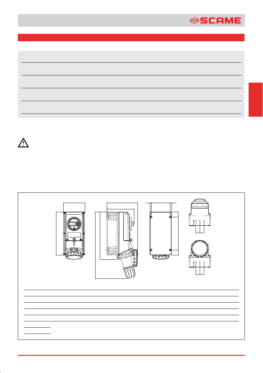
Disegno tecnico della presa interbloccata
MP36510 ZP90767-73
164
164
164
164
164
203
N
MM
F
G
H
I
L
M
114,5
114,5
114,5
114,5
114,5
150
7,75
7,75
7,75
7,75
7,75
8,3
198
198
198
198
198
310
31
31
31
31
31
35
25
25
25
25
25
32,5
N
33,5
33,5
33,5
33,5
33,5
40
ADVANCE-GRP
Via Costa Erta 15 Parre BG ITALY
IMQ 11 ATEX 010
Ta .: -25°C to +60°C IP66
II 2D
Ex tb IIIC T90°C Db
503.6387-F
2022
0051
AND WAIT AT LEAST 15 MINUTES AFTER HAVING DISCONNECTED POWER
WARNING THE CABLE ENTRY POINT CAN BE EXCEED 85°C
DO NOT OPEN WHEN ENERGIZED ENCLOSURE
3P+N+ 63A - 6h
346-415V~ 50/60Hz
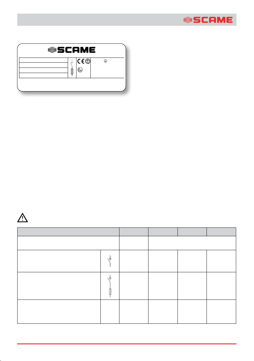
Un esempio dell’etichetta usata per la presa interbloccata certificata è qui riprodotta:
Esempio dell’etichetta adesiva.
QUESTO DOCUMENTO DEVE ESSERE LETTO ATTENTAMENTE PRIMA DELL’INSTALLAZIONE
Destinatari: elettricisti esperti o personale opportunamente addestrato.
1. NORME DI SICUREZZA
Le prese interbloccate della serie ADVANCE-GRP sono utilizzate per installazioni fisse in ambienti a potenziale rischio di esplosione
per la presenza di polveri combustibili classificati come Zona 21.
Queste istruzioni di installazione, uso e manutenzione devono essere conservate in luogo sicuro per permettere una consultazione
futura. Durante il funzionamento o durante le operazioni di manutenzione dell’apparato non lasciate questo manuale o altri oggetti
all’interno della custodia.
Utilizzare le prese interbloccate della serie ADVANCE-GRP solo per il loro uso approvato e mantenerle in condizioni di assoluta
integrità e pulizia. Le prese interbloccate sono state progettate per resistere ad un urto di 7J, e per essere utilizzate in normali
condizioni di vibrazione. Non sono state progettate per l’uso in ambienti soggetti a condizioni estreme di vibrazione. Il materiale
della custodia è poliestere rinforzato con fibra di vetro.
Nel caso di una installazione del prodotto non corretta, non sarà possibile garantire il modo di protezione.
Utilizzare solo parti di ricambio originali fornite da SCAME.
Nessuna modifica/lavorazione è permessa sulla presa interbloccata se non espressamente indicata in questo manuale.
NON APRIRE LA CUSTODIA IN TENSIONE SE IN PRESENZA DI ATMOSFERA ESPLOSIVA.
Rispettare sempre le norme antinfortunistiche nazionali e le istruzioni di sicurezza contenute in questo manuale ogniqualvolta
lavori sulla presa interbloccata.
Corrente nominale 16A 32A 63A
Dispositivo di comando e/o
di protezione incorporato
Interruttore di manovra sezionatore SCAME
serie Command
Fusibili 16-32A:
10:3 38 gG 63A : CH 22 X 58 63A gG
Codice
503.16...
503.32...
503.63...
503.16…F
503.32…F
503.63…F
Morsetti di alimentazione -
Coppia di serraggio (Nm)
0,8 0,8 3,6
0,8 0,8 3,6
503.16….
Terminale di terra
Dati tecnici, capacità di connessione dei morsetti e coppie di serraggio.
MP36510 ZP90767-74
-
503.32….
503.63….
1,2 1,2 3,5

ADVANCE-GRP
2. CONFORMITÀ AGLI STANDARD
Le prese interbloccate della serie ADVANCE-GRP sono destinati all’uso in, Zona 21
• EN IEC 60079-0:2018,
• EN 60079-31:2014.
3. DATI TECNICI
3.1 MODO DI PROTEZIONE EX
: II 2D Ex tb IIIC T90°C Db
Ta -25°C a +60°C
Year xxxx: anno di costruzione.
Prodotto adatto per impiego in atmosfera esplosiva.
II: Prodotto di gruppo II, installabile in impianti di superficie.
2D: Prodotto di categoria 2 per ambienti con presenza di polvere combustibile (D) idoneo ad essere installato in zona 21.
Ex tb: Prodotto con modalità di protezione “tb” secondo la norma EN 60079-31 e destinato a luoghi atmosfere potenzialmente
esplosive per la presenza di polveri combustibili.
esplosive per la presenza di polveri combustibili.
IIIC: Prodotto per gruppo di polveri IIIC, idoneo all’installazione in zone con presenza di polveri conduttrici
T90°C: Valore della temperatura massima superficiale.
Ta -25°C to +60°C: Intervallo di temperatura ambiente consentito presente nel luogo di installazione.
Db: Livello di protezione dell’apparecchiatura (EPL)
3.2 CERTIFICATO DI ESAME CE DEL TIPO
IMQ 11 ATEX 010
3.3 GRADO DI PROTEZIONE DELLA PRESA INTERBLOCCATA
IP66
3.4 MORSETTI DI ALIMENTAZIONE, CONDUTTORI COLLEGABILI, COPPIE DI SERRAGGIO E CORRENTI PRELEVABILI
Presa Cavo solido Flessibili
16A 4mm² 4mm²
32A 10mm² 10mm²
63A 25mm² 25mm²
Sezione morsetti.
Corrente
nominale
16A - - 16A 32A - - 25A 63A 55A 50A 45A 85°C (*)
Correnti prelevabili e temperatura cavo.
(*) Prevedere un cavo di alimentazione adeguato alla massima temperatura d’ingresso.
Ta 40°C Ta 50°C Ta 60°C
Corrente massima
Temperatura Cavi
IT
4. INSTALLAZIONE
L’installazione deve essere eseguita da personale esperto e adeguatamente addestrato in accordo con le leggi applicabili.
Devono essere seguite le norme impiantistiche per ambienti classificati contro il rischio di esplosione per presenza di polveri
combustibili (ad esempio: EN 60079-14, oppure altre norme/standard nazionali).
Osservare le norme di comportamento generalmente accettate nell’ambito dell’installazione di materiale elettrico, le regole antiinfortunistiche nazionali e le istruzioni di sicurezza contenute in questo manuale ogni volta che si opera sull’unità. Non aprire la
custodia sotto tensione oppure verificare che l’atmosfera non sia pericolosa. Prima di aprire il coperchio della presa interbloccata
attendere 15 minuti dalla messa fuori tensione.
MP36510 ZP90767-75

ADVANCE-GRP
4.1 ISTRUZIONI D’USO SICURO
Il grado di protezione IP della presa interbloccata deve essere mantenuto attraverso l’uso di adeguati pressacavi, guarnizioni e
il completo rispetto delle norme di installazione e delle relative istruzioni. Quando altri componenti certificati vengono assemblati
alla presa interbloccata, l’utilizzatore deve tenere in considerazione ogni eventuale limitazione indicata sui rispettivi certificati.
L’attrezzatura per forare la presa interbloccata deve essere idonea al materiale (poliestere rinforzato con fibra di vetro) e devono
essere usate le velocità adeguate a non danneggiare le pareti. Le forature devono ricadere all’interno dell’area forabile definita
per ciascuna parete (vedi Fig.3) e devono essere eseguiti a regola d’arte, prive di sbavature. Le pareti predisposte per la foratura
hanno spessore 5,7mm. Le forature non sono idonee ad essere filettate.
Le forature per le entrate dei cavi devono essere realizzate in conformità al presente manuale.
Conservare la presa interbloccata in magazzino all’interno del suo imballo originale, in modo da proteggerlo da ingresso di polvere
o umidità: la presa interbloccata deve essere tolta dall’imballo solo prima dell’installazione.
La presa interbloccata deve essere installata integra e priva di qualsiasi danno.
Le prese interbloccate devono essere installate in modo tale che la polvere non penetri nella presa con o senza spina inserita. Per
ridurre al minimo tale rischio, nal caso in cui il coperchio presa sia stato accidentalmente dimenticato aperto, la presa deve essere
montata e posizionata ad un angolo non superione ai 45° rispetto alla verticale, con l’apertura rivolta verso il basso.
Istruzioni da seguire per l’installazione corretta della presa interbloccata:
1) Leggere le istruzioni di installazione, uso e manutenzione relative alla presa interbloccata.
2) Utilizzando le dimensioni di fissaggio riportate in Figura 1, marcare le posizioni dei fori di fissaggio sulla parete di installazione.
3) Eseguire i fori di fissaggio sulla parete d’installazione e filettare i fori (se richiesto).
4) Togliere la presa interbloccata dall’imballo verificando che non abbia subito danni durante il trasporto.
5) Verificare che il coperchio e la base siano puliti e privi di difetti.
6) Togliere la piastra con fissati tutti gli elementi interni dalla base della presa interbloccata.
7) Portare la base della presa interbloccata nella posizione di montaggio sulla parete di installazione, utilizzando ogni assistenza
necessaria al fine di prevenire infortuni.
8) Fissare l’apparato ripetendo le seguenti operazioni per ogni foro di fissaggio:
a) Infilare la vite di fissaggio nel foro di fissaggio
b) Serrare il bullone (se il foro è passante) oppure avvitare completamente la vite di fissaggio.
9) Verificare che il fissaggio sia sicuro.
10) Procedere al montaggio dei pressacavi (se non pre-montati) seguendo le istruzioni del costruttore.
11) Inserire la piastra con fissati tutti gli elementi interni nella base della presa interbloccata.
12) Infilare i cavi nell’apparato avendo cura di fissare le armature dei cavi (se presenti).
13) Procedere al cablaggio secondo lo schema elettrico in dotazione dell’installatore.
Prima di chiudere la presa interbloccata:
14) Verificare che tutti i materiali estranei siano stati rimossi dall’interno della presa interbloccata: non lasciate queste istruzioni
all’interno.
15) Verificare che le guarnizioni siano integre ed installate correttamente.
16) Chiudere il coperchio serrando opportunamente le viti al fine di garantire il grado IP. La coppia di serraggio delle viti è 1,2 Nm.
17) Conservate in luogo sicuro queste istruzioni per una consultazione futura.
4.2 ACCESSORI DISPONIBILI
Gli accessori in dotazione devono essere montati prima dell’installazione dell’apparato, da personale esperto, seguendo le modalità
riportate nei relativi fogli istruzione.
A) Kit microswitch per il controllo presenza spina (Art. 579.0100 per 16-32-63A)
B) Contatto ausiliario (1 contatto NO + 1 contatto NC) (Fam. art. 590.PL00400X).
Solo accessori originali ed approvati da SCAME devono essere utilizzati.
4.3 CABLAGGIO DEI TERMINALI
I cablaggi devono essere eseguiti a regola d’arte.
Usare solo attrezzatura di dimensione corretta per eseguire il cablaggio.
MP36510 ZP90767-76

ADVANCE-GRP
B
A
E
C
A
Ciascun morsetto può ospitare un solo filo conduttore, a meno che più fili conduttori non siano stati preventivamente uniti in
modo idoneo. I cavi elettrici devono avere un isolamento adeguato alla tensione. I morsetti non utilizzati devono essere serrati
completamente.
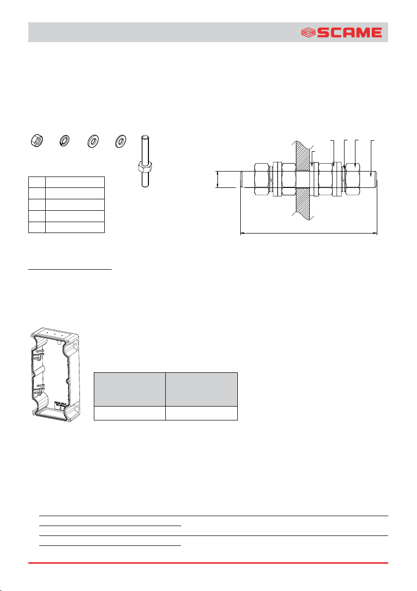
4.4 COLLEGAMENTO A TERRA
Le prese interbloccate devono essere collegate ai circuiti di protezione/terra in accordo con le regole di installazione dell’impianto.
Il morsetto di terra interno dovrà essere collegato ad un circuito equipotenziale di protezione o messa a terra prima di procedere
con l’alimentazione dell’apparato.
X2 X5 X1A1X3X
B CD
A Dado esagonale
B Grower
A
E
D
C Rondella
D Rondella in teflon
E Perno di terra
B
Perno di terra Art. 644.E650 - 644.E651 - 644.E1075 - 644.E1076
4.5 COMPONENTI
Utilizzare solo parti di ricambio originali.
I componenti da incorporare nell’apparato o le parti di ricambio originali devono essere installati da persone adeguatamente
addestrate.
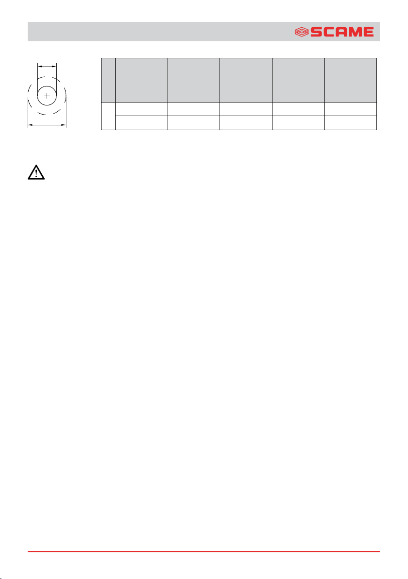
4.6 AREE FORABILI
Le aree indicate devono essere forate rispettando le distanze minime, diametri e numero di fori massimo indicate nella tabella.
IT
16A/32A
WxD
(mm2)
63A
WxD
(mm2)
80x45 (A=A) 110x55 (A=A)
A
Dimensioni aree forabili.
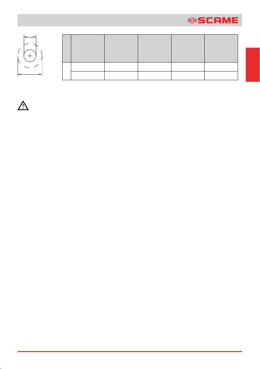
4.7 PRESSACAVI
Utilizzare solo pressacavi ATEX idonei alle sostanze, temperature e zona di installazione (marcati II 2D Ex tb IIIC con grado di
protezione minimo IP66). Assicurarsi che i pressacavi selezionati siano adatti ai cavi, così da impedire allentamenti e garantire
una tenuta permanente contro l’ingresso di umidità e polvere.
Le entrate di cavo non utilizzate se aperte, devono essere chiuse con tappi certificati ATEX idonei alle sostanze, temperature e
zona di installazione (marcati II II 2D Ex tb IIIC con grado di protezione minimo IP66).
• Per l’installazione dei pressacavi (oggetto di certificazione ATEX separata), seguire le relative istruzioni del costruttore in
particolare coppia di serraggio e presenza guarnizioni.
• L’ingresso cavi nella versione da 63A DEVE essere effettuato tramite la relativa muffola provvista di un’unica entrata cavi tipo
M50x1,5 (Kit muffola e pressacavo art. 579.EX0201)
MP36510 ZP90767-77
ADVANCE-GRP
CLEARANCE
a
GLAND
Dimensione
nominale
pressacavo
M
Dimensione
nominale
pressacavo
PG
Dimensione
foro
(GLAND)
a (mm)
Distanza
minima
(CLEARANCE)
b (mm)
Area A
n°
M32 33 50 2
b
16/32A
Pg29 37,5 50 2
Distanza minima e dimensione pressacavo.
5. USO, MANUTENZIONE E RIPARAZIONE
Ispezione e manutenzione di queste prese interbloccate devono essere eseguite da personale adeguatamente addestrato
in accordo con la regola dell’arte secondo le norme impiantistiche e di manutenzione per ambienti classificati contro il
rischio di esplosione per presenza di polveri combustibili (ad esempio: EN 60079-14, oppure altre norme/standard nazionali).
Durante la manutenzione periodica verificare sempre i componenti da cui dipende il grado di protezione ( M6/M10 - Earth-Stud
Otpional) ed in modo particolare le guarnizioni. La riparazione può essere eseguita solo da SCAME.
5.1 SPINE DA UTILIZZARE
Utilizzare solo spine certificate ATEX serie OPTIMA-EX che sono idonee per essere impiegate in Zona 21 con grado di protezione IP66.
5.2 LUCCHETTO DA UTILIZZARE
Per una corretta lucchettabilità della manopola in posizione “0” oppure “1”, utilizzare lucchetti con Ø arco 6,3mm.
5.3 COPERCHIO PRESE
Nel caso di spina disinserita si deve mantenere il coperchio della presa interbloccata completamente avvitato.
5.4 DISPOSITIVI DI PROTEZIONE INCORPORATI
Nelle versioni con basi portafusibili, l’apertura frontale per le operazioni di controllo, manutenzione e sostituzione fusibile deve
essere effettuata con impianto sezionato. In caso di sostituzione dei fusibili, utilizzare fusibili di tipo:
- 16A/32A: tipo CH: 10,3x38mm gG
- 63A: tipo 22x58mm gG.
5.5 MANUTENZIONE PERIODICA
L’attività di manutenzione periodica è necessaria a garantire il corretto funzionamento ed il mantenimento del grado protezione
della presa interbloccata.
1) Verificare le condizioni di integrità della guarnizione ogni volta che la custodia viene aperta.
2) Verificare che le viti di chiusura siano tutte in posizione e ben serrate ogni volta che la custodia viene chiusa.
3) Verificare che le viti/bulloni di fissaggio a parete siano ben serrate e prive di corrosione ogni anno.
4) Verificare la tenuta dei pressacavi ogni anno.
5) Verificare eventuali danni alla custodia ogni anno.
6) Verificare che i morsetti a vite siano serrati come indicato dal costruttore.
7) In ambienti con presenza di polvere combustibile è necessario pulire periodicamente la superficie della parete superiore della
custodia, in modo da evitare che lo spessore di polvere depositata superi i 5 mm.
5.6 AGGRESSIONE CHIMICA
Le prese interbloccate della serie ADVANCE-GRP sono costruite usando:
- Poliestere rinforzato fibra di vetro per base e coperchio involucro principale;
- Lega termoplastica (PC-XILOXANE) per coperchio e ghiera presa;
- Gomma termoplastica per guarnizione base-coperchio e mostrina, guarnizione manopola (gomma vulcanizzata) e vetrino Led
(silicone);
- Gomma termoplastica (16-32A); Siliconica (63A) per guarnizione coperchio presa.
È necessario considerare attentamente l’ambiente in cui installare le prese interbloccate e determinare la sostenibilità di questi
materiali all’eventuale presenza di agenti chimici o atmosfere corrosive.
5.7 SMALTIMENTO
Lo smaltimento del prodotto deve essere fatto in base alle regole nazionali di smaltimento e riciclaggio dei rifiuti industriali.
MP36510 ZP90767-78

ADVANCE-GRP
DICHIARAZIONE DI CONFORMITÀ UE
Noi: SCAME PARRE S.p.A.
Via Costa Erta, 15 – 24020 Parre (BG) ITALY
Dichiariamo che i seguenti prodotti :
Presa interbloccata Tipo ADVANCE-GRP Codice 503.EXxxxx oppure 503.EXxxxx-F
(Il codice prodotto specifico e il numero di serie sono indicati in targa e sull’imballo.)
ai quali la presente dichiarazione si riferisce sono conformi a:
Direttiva ATEX 2014/34/UE
Direttiva LVD 2014/35/UE
La conformità è stata verificata sulla base delle seguenti norme:
EN IEC 60079-0:2018
EN 60079-31:2014
EN 60309-1:1999 +A1:2007 +A2:2012
EN 60309-2:1999 +A1:2007 +A2:2012
EN 60309-4:2007 +A1:2012
Marcatura Direttiva ATEX:
0051
II 2D
Modo di protezione ATEX: (*)
Ex tb IIIC T90°C Db
IP66
Tamb : -25°C a +60°C
IT
(*) I dati specifici relativi a: temperatura superficiale massima e temperatura ambiente sono indicato
sul piatto.
I modelli appartenenti a questa famiglia di prodotti sono oggetto del certificato IMQ 11ATEX0010 (in
conformità all’Allegato III della Direttiva ATEX) e alla notifica del sistema di qualità IMQ 08 ATEX 013 Q (in
conformità all’Allegato VII della Direttiva ATEX).
AInformazioni aggiuntive :
La valutazione EMC del produttore stabilisce che l’apparato in questione è intrinsecamente benigno in termini
di compatibilità elettromagnetica (sia per i requisiti di emissione che di immunità) quindi ai sensi dell’art 2(2d)
della 2014/30/UE, la direttiva EMC non trova applicazione.
Parre, 04/02/2022 SCAME PARRE S.p.A.
Direttore Marketing & Sviluppo prodotto
Ing. Giampietro Camilli
VIA COSTA ERTA, 15 - 24020 PARRE (BG) ITALY - TEL. +39 035 705000 - FAX +39 035 703122 -
CAP. SOC: € 5000000 INT. VERS. - REG. SOC. TRIB. BG N. 7421 - C.C.I.A.A. 136163 / C.C.P. 12614244 - COD. FISC. / PARTITA IVA/VAT/TVA 00137900163
MP36510 ZP90767-79
SCAME PARRE S.p.A.
www.scame.com - scame@scame.com

ADVANCE-GRP
ENGLISH
CONTENTS
1. Safety information 11
2. Compliance with standards 12
3. Technical data 12
4. Installation 12
5. Use, maintenance and repairs 15
The following warning phrases are affixed to the product shell by means of an additional label, made of the same material, or
data plate:
Do not open the energized enclosure.
CAUTION: keep the socket cover ring nut screwed in when the interlocked socket is not used and screw in the
relevant plug ring nut when the plug is inserted.
CAUTION: after cutting out the power supply, wait 15 minutes before opening the enclosure.
For the 63A version:
CAUTION: Cable entry may reach a temperature of 85°C.
BE
F
2P+
-
3P+
-
3P+N+
2/3P+
3P+N+
2P+
-
3P+
-
3P+N+
16A
16A
-
-
-
63A
63A
-
16A
32A
32A
63A
A
A
B
260
130
260
130
260
130
260
130
260
130
380
170
360
365
390
390
400
550
D
C
C
D
E
280
170
282
175
282
182
285
189
286
185
420
225
Technical drawing of the interlocked socket.
MP36510 ZP90767-710
164
164
164
164
164
203
GHH
LLI
N
MM
N
MM
F
G
H
I
114,5
114,5
114,5
114,5
114,5
150
7,75
7,75
7,75
7,75
7,75
8,3
198
198
198
198
198
310
L
31
25
31
25
31
25
31
25
31
25
35
32,5
(mm)
M
N
33,5
33,5
33,5
33,5
33,5
40

ADVANCE-GRP
Via Costa Erta 15 Parre BG ITALY
IMQ 11 ATEX 010
Ta .: -25°C to +60°C IP66
II 2D
Ex tb IIIC T90°C Db
503.6387-F
2022
0051
AND WAIT AT LEAST 15 MINUTES AFTER HAVING DISCONNECTED POWER
WARNING THE CABLE ENTRY POINT CAN BE EXCEED 85°C
DO NOT OPEN WHEN ENERGIZED ENCLOSURE
3P+N+ 63A - 6h
346-415V~ 50/60Hz
An example of the label used for the certified interlocked socket is shown below:
Details of the adhesive label or steel plate.
READ THIS DOCUMENT CAREFULLY PRIOR TO THE INSTALLATION
Recipients: expert electricians or duly trained personnel.
1. SAFETY INFORMATION
The interlocked sockets of the ADVANCE-GRP Series are used for fixed installations in environments with a potential risk of
explosion due to the presence of combustible dust classified as Zone 21.
These installation, use and maintenance instructions must be kept in a safe place for future reference. During operation or
maintenance jobs on the device, do not leave this manual or other objects inside the enclosure.
Use the ADVANCE-GRP Series interlocked sockets for their approved use only, and keep them fully intact and perfectly clean. The
interlocked sockets have been designed to withstand shocks of 7J, and to be used under normal vibration conditions.
They have not been designed for use in environments subject to extreme vibrations. The enclosure is made of fibreglassreinforced polyester.
The type of protection cannot be guaranteed if the product is not installed correctly.
Use only original spare parts supplied by SCAME.
No modification/work is allowed on the interlocked socket unless specifically indicated in this manual.
DO NOT OPEN THE ENERGIZED ENCLOSURE IN PRESENCE OF AN EXPLOSIVE ATMOSPHERE.
Always observe with national accident-prevention rules and with the safety instructions contained in this manual whenever
you work on the interlocked socket.
Nominal current 16A 32A 63A
Built-in control and/or protection device Code
Power supply terminals -
Tightening torque (Nm)
EN
SCAME Command Series
switch-disconnector
Fuses 16-32A:
10:3 38 gG - 63A : CH 22 X 58 63A gG
Earth terminal
Technical data, connection capacities of the terminals and tightening torques.
MP36510 ZP90767-711
-
503.16...
503.32...
503.63...
503.16…F
503.32…F
503.63…F
503.16….
503.32….
503.63….
0,8 0,8 3,6
0,8 0,8 3,6
1,2 1,2 3,5

ADVANCE-GRP
2. COMPLIANCE WITH STANDARDS
The interlocked sockets of the ADVANCE-GRP Series are intended for use in Zone 21
• EN IEC 60079-0:2018,
• EN 60079-31:2014.
3. TECHNICAL DATA
3.1 TYPE OF EX PROTECTION
: II 2D Ex tb IIIC T90°C Db
Ta -25°C to +60°C
Year xxxx: year of manufacture.
: Product suited for use in explosive atmosphere.
II: Product classified as belonging to group II, installable in above-ground systems.
2D: Product classified as belonging to category 2 for environments featuring the presence of combustible dust (D) suited for
installation in Zone 21.
Ex tb: Product with “tb” protection mode in accordance with the EN 60079-31 standard and intended for places with potentially
explosive atmospheres due to the presence of combustible dusts.
IIIC: Equipment classified as group IIIC, product suited to be used in presence of conductive dust.
T90°C: Maximum surface temperature value.
Ta -25°C to +60°C: Permitted ambient temperature range present at the installation site.
Db: Equipment Protection Level (EPL).
3.2 EC TYPE TEST CERTIFICATE
IMQ 11 ATEX 010
3.3 DEGREE OF PROTECTION OF THE INTERLOCKED SOCKET
IP66
3.4 POWER SUPPLY TERMINALS, CONNECTING CONDUCTORS, TIGHTENING TORQUES AND DRAWABLE CURRENTS
Socket Solid Wire Strand-Wire
16A 4mm² 4mm²
32A 10mm² 10mm²
63A 25mm² 25mm²
Terminal section.
Rated
current
16A - - 16A 32A - - 25A 63A 55A 50A 45A 85°C (*)
Drawable currents and cable temperature
(*) Provide a power supply cable suited for the maximum entry temperature.
Ta 40°C Ta 50°C Ta 60°C
Maximum current
Cable temperature
4. INSTALLATION
The installation must be carried out by suitably trained and skilled personnel in compliance with applicable laws. Plant-
engineering standards for environments classified against the risk of explosion due to the presence of combustible dust
must be observed (for example: EN 60079-14, or other national regulations/standards).
Comply with generally accepted rules of behaviour for installation of electrical materials, with national accident-prevention rules
and with the safety instructions contained in this manual whenever you work on the unit. Do not open the energized enclosure or
make sure the atmosphere is not dangerous. Before you open the cover of the interlocked socket, wait 15 minutes after cutting
out the power supply.
MP36510 ZP90767-712

ADVANCE-GRP
4.1 INSTRUCTIONS FOR SAFE USE
The IP degree of protection of the interlocked socket must be maintained by using suitable cable glands and gaskets and by
fully complying with the installation rules and the relevant instructions. When other certified components are assembled in the
interlocked socket, the user must take into account any limitation indicated on the respective certificates.
The equipment used to drill the interlocked socket must be suited for the material (fibreglass-reinforced polyester) and used at
appropriate speeds in order to avoid damaging the walls. The holes must be drilled within the drillable area defined for each wall
(see Fig. 3), and they must be carried out up to standards, without any burrs. The walls preset for drilling are 5.7 mm thick. The
drilled holes are not suited for threading.
The holes for cable entry must be drilled in compliance with this manual.
Store the interlocked socket in a warehouse inside its original packaging in order to protect it from dust or humidity. Remove the
interlocked socket from its package right before its installation.
The interlocked socket must be installed intact and damage-free.
The interlocked sockets must be installed so that dust does not penetrate the socket with or without the plug inserted. To minimize
this risk, in case the socket cover is accidentally left open, the socket must be assembled and positioned at a maximum angle of
45° with respect to the vertical, with the opening facing downward.
Instructions for proper installation of the interlocked socket:
1) Read the installation use and maintenance instructions for the interlocked socket.
2) Using the fixing dimensions shown in Figure 1 , mark the positions of the fixing holes on the installation wall.
3) Drill the fixing holes on the installation wall and thread the holes (if required).
4) Remove the interlocked socket from its package, making sure that it has not been damaged during shipping.
5) Check that the cover and the base are clean and defect-free.
6) Remove the plate with all the internal elements fixed to it from the base of the interlocked socket.
7) Place the base of the interlocked socket in the assembly position on the installation wall, using any assistance necessary in
order to prevent accidents.
8) Secure the device by repeating the following operations for each fixing hole:
a) Insert the clamping screw into the fixing hole.
b) Tighten the bolt (in case of a through-hole) or tighten the clamping screw completely.
9) Make sure the fixing is secure.
10) Proceed with the assembly of the cable glands (if not preassembled) following the manufacturer’s instructions.
11) Insert the plate with all the internal elements fixed to it into the base of the interlocked socket.
12) Insert the cables in the device, being careful to secure the cable armours (if applicable).
13) Proceed with the wiring according to the wiring diagram issued to the installer.
Before you close the interlocked socket:
14) Check that all foreign materials have been removed from inside the interlocked socket: do not leave these instructions inside.
15) Check that the gaskets are intact and properly installed.
16) Close the cover by duly tightening the screws in order to guarantee the IP degree of protection. The tightening torque of the
screws is 1.2 Nm.
17) Keep these instructions in a safe place for future reference.
4.2 AVAILABLE ACCESSORIES
The accessories supplied with the interlocked socket must be assembled prior to the installation of the device, by skilled personnel,
following the methods indicated in the relevant instruction sheets.
A) Kit with microswitch for plug presence check (Art. 579.0100 for 16-32-63A)
B) Auxiliary contact (1 NO contact + 1 NC contact ) (Fam. art. 590.PL00400X).
Use original, SCAME-approved accessories only.
4.3 TERMINALS WIRINGS
The wiring must be carried out according to the highest standards.
Use only equipment with proper size for the wiring.
EN
MP36510 ZP90767-713
ADVANCE-GRP
B
A
E
C
A
Each terminal can host a single conductor, unless several conductors have been previously joint in a suitable manner. The electrical
cables must have insulation suited to the voltage. Unused terminals must be completely tightened.
4.4 EARTH CONNECTION
The interlocked sockets must be connected to the protection/earthing circuits incompliance with the system installation rules.
The internal earthing terminal will have to be connected to an equipotential protection ( M6/M10 - Earth-Stud Otpional) or earthing
circuit before powering the device.
X2 X5 X1A1X3X
B CD
A Hex Nut
B Grower
A
E
D
C Washer
D Teflon Washer
E Earth pin
B
Earth stud Art. 644.E650 - 644.E651 - 644.E1075 - 644.E1076
4.5 COMPONENTS
Use original spare parts only.
The components to be incorporated in the device or the original spare parts must be installed by suitably trained personnel.
4.6 DRILLABLE AREAS
The areas indicated must be drilled in compliance with the minimum distances, diameters and maximum number of holes indicated
in Table.
16A/32A
WxD
(mm2)
63A
WxD
(mm2)
80x45 (A=A) 110x55 (A=A)
A
Dimensions of drillable areas.
4.7 CABLE GLANDS
Use only ATEX cable glands suitable for the substances, temperatures and installation zone (marked II 2D Ex tb IIIC with minimum
degree of protection IP66). Make sure that the selected cable glands are suited for the cables, so as to prevent any loosening and
guarantee a permanent seal against humidity and dust.
Unused cable entries, if open, must be closed with ATEX-certified plugs suited for the substances, temperatures and installation
zone (marked II 2D Ex tb IIIC with minimum degree of protection IP66).
• For installation of the cable glands (subject to separate ATEX certification), follow the manufacturer’s instructions, specifically
the tightening torque and the presence of gaskets.
• Cable entry in the 63A version MUST be carried out through the relevant muffle equipped with single cable entry type M50x1.5
(Kit with muffle and cable gland art. 579.EX0201)
MP36510 ZP90767-714
ADVANCE-GRP
CLEARANCE
a
GLAND
b
Cable gland
nominal size
M
Cable gland
nominal size
PG
Hole size
(GLAND)
a (mm)
M32 33 50 2
16/32A
Pg29 37,5 50 2
Minimum
distance
(CLEARANCE)
b (mm)
Area A
n°
Cable gland dimension and minimum distance.
5. USE, MAINTENANCE AND REPAIRS
The inspection and maintenance of these interlocked sockets must be carried out by duly trained personnel in accordance
with the highest standards and according to plant-engineering and maintenance rules for environments classified against
the risk of explosion due to the presence of combustible dust (for example: EN 60079-14 or other national regulations/standards).
When carrying out routine maintenance, always check the components responsible for the degree of protection, in particular the
gaskets. Repairs can only be carried out by SCAME.
5.1 PLUGS TO BE USED
Use only ATEX-certified OPTIMA-EX Series plugs suited for installation in Zone 21 with IP66 degree of protection.
5.2 LOCK TO BE USED
For proper locking of the handle in position “0” or “1”, use locks with arc Ø of 6.3 mm.
5.3 SOCKET COVER
If the plug is not inserted, the cover of the interlocked socket must remain fully screwed in.
5.4 BUILT-IN PROTECTION DEVICES
In the versions with fuse holder bases, the front opening for control, maintenance and replacement of the fuse must be done with
the system disconnected. If the fuses need to be changed, use the following types of fuses:
- 16A/32A: type CH: 10.3x38mm gG
- 63A: type 22x58mm gG.
5.5 ROUTINE MAINTENANCE
Routine maintenance is necessary in order to guarantee proper operation and preservation of the degree of protection of the
interlocked socket.
1) Check that the gasket is intact every time the enclosure is opened.
2) Check that the closing screws are all in place and well-tightened every time the enclosure is closed.
3) Make sure that the screws/bolts used to fasten the enclosure to the wall are well-tightened and corrosion-free on a yearly basis.
4) Check the seal of the cable glands on a yearly basis.
5) Check for any damage to the enclosure on a yearly basis.
6) Make sure the screw terminals are tightened as indicated by the manufacturer.
7) In environments with the presence of combustible dust, the surface of the upper wall of the enclosure must be cleaned
periodically, so as to prevent the thickness of the deposited dust from exceeding 5 mm.
5.6 CHEMICAL ATTACK
The interlocked sockets of the ADVANCE-GRP Series are made using:
- Fibreglass-reinforced polyester for the base and for the main enclosure cover;
- Thermoplastic alloy (PC-XILOXANE) for socket cover and ring nut;
- Thermoplastic rubber for base-cover gasket and plate, knob gasket (vulcanized rubber) and LED glass (silicone);
- Thermoplastic rubber (16-32A); Silicone rubber (63A) for socket cover gasket.
The environment where the interlocked sockets will be installed must be considered carefully in order to ascertain the compatibility
of these materials with the presence of chemical agents or corrosive atmospheres.
5.7 DISPOSAL
The product must be disposed of in compliance with national rules on the disposal and recycling of industrial waste.
EN
MP36510 ZP90767-715
ADVANCE-GRP
DECLARATION OF CONFORMITY EU
The company: SCAME PARRE S.p.A.
Via Costa Erta, 15 – 24020 Parre (BG) ITALY
Hereby declares that the following products:
Interlocked socket type ADVANCE-GRP Code 503.EXxxxx or 503.EXxxxx-F
(The specific product code and the serial number are indicated in the plate and on the packing.)
to which this declaration refers to, comply with:
ATEX DIRECTIVE 2014/34/EU
LVD DIRECTIVE 2014/35/EU
Compliance was verified on the basis of the following standards:
EN IEC 60079-0:2018
EN 60079-31:2014
EN 60309-1:1999 +A1:2007 +A2:2012
EN 60309-2:1999 +A1:2007 +A2:2012
EN 60309-4:2007 +A1:2012
ATEX Directive Marking:
0051
(*) The specific data pertaining to: maximum surface temperature and ambient temperature are
indicated on the plate.
The models belonging to this product family are covered by the IMQ 11ATEX0010 certificate (in compliance
with Annex III of the ATEX Directive) and the quality system notification IMQ 08 ATEX 013 Q (in compliance
with Annex VII of the ATEX Directive).
Additional information :
The manufacturer EMC assessment establishes that the apparatus concerned is inherently benign in terms
of electromagnetic compatibility (both for emission and immunity requirements) therefore according to Article
2(2d) of the 2014/30/UE, the EMC directive shall not apply.
Parre, 04/02/2022 SCAME PARRE S.p.A.
Direttore Marketing & Sviluppo prodotto
Ing. Giampietro Camilli
VIA COSTA ERTA, 15 - 24020 PARRE (BG) ITALY - TEL. +39 035 705000 - FAX +39 035 703122 -
CAP. SOC: € 5000000 INT. VERS. - REG. SOC. TRIB. BG N. 7421 - C.C.I.A.A. 136163 / C.C.P. 12614244 - COD. FISC. / PARTITA IVA/VAT/TVA 00137900163
MP36510 ZP90767-716
II 2D
SCAME PARRE S.p.A.
ATEX protection mode: (*)
Ex tb IIIC T90°C Db
IP66
Tamb. : -25°C to +60°C
www.scame.com - scame@scame.com
ADVANCE-GRP
FRANÇAIS
SOMMAIRE
1. Normes de sécurité 18
2. Conformité aux normes 19
3. Données techniques 19
4. Installation 19
5. Utilisation, entretien et réparation 22
Les phrases d’avertissement suivantes sont placées sur l’enveloppe du produit avec une étiquette supplémentaire, en même
matériau, ou une plaque.
Ne pas ouvrir le boîtier sous tension.
AVERTISSEMENT : maintenir la douille du bouchon de la prise vissée lorsque la prise
interverrouillée n’est pas utilisée et visser la douille de la fiche quand celle-ci est enfilée.
AVERTISSEMENT : après la mise hors tension, attendre 15 minutes avant d'ouvrir le boîtier.
Pour la version de 63A :
AVERTISSEMENT : l’entrée peut atteindre dune température de 85°C.
BE
F
A
D
C
GHH
LLI
N
MM
N
MM
(mm)
FR
2P+
-
3P+
-
3P+N+
2/3P+
3P+N+
2P+
-
3P+
-
3P+N+
16A
16A
-
-
-
63A
63A
-
16A
32A
32A
63A
260
260
260
260
260
380
A
B
C
D
130
130
130
130
130
170
360
365
390
390
400
550
280
282
282
285
286
420
E
170
175
182
189
185
225
Schéma technique de la prise interverrouillée.
MP36510 ZP90767-717
164
164
164
164
164
203
F
G
H
I
L
M
114,5
114,5
114,5
114,5
114,5
150
7,75
7,75
7,75
7,75
7,75
8,3
198
198
198
198
198
310
31
31
31
31
31
35
25
25
25
25
25
32,5
N
33,5
33,5
33,5
33,5
33,5
40

ADVANCE-GRP
Via Costa Erta 15 Parre BG ITALY
IMQ 11 ATEX 010
Ta .: -25°C to +60°C IP66
II 2D
Ex tb IIIC T90°C Db
503.6387-F
2022
0051
AND WAIT AT LEAST 15 MINUTES AFTER HAVING DISCONNECTED POWER
WARNING THE CABLE ENTRY POINT CAN BE EXCEED 85°C
DO NOT OPEN WHEN ENERGIZED ENCLOSURE
3P+N+ 63A - 6h
346-415V~ 50/60Hz
Un exemple d’étiquette utilisée pour la prise interverrouillée certifiée est reproduit ci-dessous:
Détails de l’étiquette adhésive ou de la plaque en acier.
LIRE CE DOCUMENT AVEC ATTENTION AVANT DE PROCÉDER À L’INSTALLATION
Destinataires: électriciens qualifiés ou personnel spécialisé.
1. NORMES DE SÉCURITÉ
Les prises interverrouillées de la série ADVANCE-GRP sont utilisées pour les installations dans des endroits présentant un risque
potentiel d’explosion en raison de la présence de poussières combustibles classés comme Zone 21.
Ces instructions d’installation, d’utilisation et entretien doivent être rangées en lieu sûr afin de pouvoir être consultées par la
suite. Pendant le fonctionnement ou pendant les opérations d’entretien de l’appareil, ne laissez ni ce manuel ni tout autre objet
à l’intérieur du carter.
N’utilisez les prises interverrouillées de la série ADVANCE-GRP que pour leur usage approuvé et conservez-les parfaitement
propres et intactes. Les prises interverrouillées ont été conçues pour résister à des chocs de 7J et pour être utilisées dans des
conditions normales de vibration. Elles n’ont pas été conçues pour être utilisées dans des environnements soumis à de très fortes
vibrations. Le matériau du boîtier est le polyester renforcé de fibre de verre.
Si le produit est mal installé, il est impossible d’en garantir la protection.
N’utilisez que des pièces détachées originales fournies par SCAME.
Aucun changement/usinage n’est autorisé sur la prise interverrouillée à moins d’une indication expresse de ce manuel.
NE PAS OUVRIR LE BOÎTIER SOUS TENSION SI L’ATMOSPHÈRE EST EXPLOSIVE
Respectez toujours les règles nationales de prévention des accidents et les consignes de sécurité contenues dans ce
manuel chaque fois que vous travaillez sur la prise verrouillée.
Courant nominal 16A 32A 63A
Dispositif de commande et/ou
de protection intégré
Interrupteur de manoeuvre disjoncteur SCAME
Série Command
Fusibles 16-32A:
10:3 38 gG - 63A : CH 22 X 58 63A gG
Código
503.16...
503.32...
503.63...
503.16…F
503.32…F
503.63…F
Bornes d’alimentation Couple de serrage (Nm)
0,8 0,8 3,6
0,8 0,8 3,6
503.16….
Borne de terre
Informations techniques, capacité de connexion des bornes et couples de serrage.
MP36510 ZP90767-718
-
503.32….
503.63….
1,2 1,2 3,5

ADVANCE-GRP
2. CONFORMITÉ AUX NORMES
Les prises interverrouillées de la série ADVANCE-GRP sont destinées à l’usage en Zone 21
• EN IEC 60079-0:2018,
• EN 60079-31:2014.
3. DONNÉES TECHNIQUES
3.1 MODE DE PROTECTION EX
: II 2D Ex tb IIIC T90°C Db
Ta -25°C pour +60°C
Year xxxx: année de construction
: Produit utilisable en atmosphère explosive
II: Produit du groupe II, installable dans des installations de surface.
2D: Produit de catégorie 2 pour les environnements en présence de poussières combustibles (D) utilisable si installé en zone 21.
Ex tb: Produit avec mode de protection « tb » conforme à la norme EN 60079-31 et destiné aux lieux potentiellement atmosphères
explosives dues à la présence de poussières combustibles.
IIIC: Appareil de groupe IIIC, produit adapté à l’utilisation en présence de poussières conductrices.
T90°C: valeur maximum de la température superficielle.
Ta -25°C to +60°C: Plage de température ambiante autorisée présente sur le site d'installation.
Db: Niveau de protection de l’appareil (EPL)
3.2 CERTIFICAT D’EXAMEN CE DU TYPE
IMQ 11 ATEX 010
3.3 DEGRÉ DE PROTECTION DE LA PRISE INTERVERROUILLÉE
IP66
3.4 BORNES D’ALIMENTATION, CONDUCTEURS CONNECTABLES, COUPLES DE SERRAGE ET COURANTS PRÉLEVABLES
Prise Cable solide Flexibles
16A 4mm² 4mm²
32A 10mm² 10mm²
63A 25mm² 25mm²
Section bornes.
FR
Courant
nominal
16A - - 16A 32A - - 25A 63A 55A 50A 45A 85°C (*)
Courants prélevables et température du câble.
(*) Prévoyez un câble d’alimentation adapté à la température maximum d’entrée.
4. INSTALLATION
L’installation doit être exécutée par du personnel spécialement formé conformément aux lois applicables. Dit personnel
devra respecter les normes sur les installations dans des environnements classés contre le risque d’explosion due à la
présence de poussières combustible (par exemple : EN 60079-14, ou d’autres normes/standards nationaux).
Respectez les règles de comportement généralement admises pour installer le matériel électrique, les règlements nationaux
de prévention des accidents et les instructions de sécurité contenues dans ce manuel chaque fois que vous opérez sur l’unité.
N’ouvrez pas le boîtier sous tension, à moins de vérifier si l’atmosphère est sans danger. Avant d’ouvrir le couvercle de la prise
interverrouillée, attendez 15 minutes à compter de la mise sous tension.
MP36510 ZP90767-719
Ta 40°C Ta 50°C Ta 60°C
Courant maximal
Température Câbles

ADVANCE-GRP
4.1 INSTRUCTIONS D’UTILISATION SÛRE
Le degré de protection IP de la prise interverrouillée doit être conservé à l’aide de presse-étoupes et de joints appropriées et en
respectant scrupuleusement les normes d’installation et les instructions. Lorsque d’autres composants certifiés sont montés sur
la prise interverrouillée, l’utilisateur doit tenir compte des éventuelles limites indiquées sur les certificats respectifs.
Pour percer la prise interverrouillée utilisées un équipement adapté au matériau (polyester renforcé de fibre de verre) et des
vitesses qui n’endommagent pas les murs. Les trous doivent se trouver dans une surface perçable définie sur chaque mur (cf.
Fig.3) et être percés dans les règles de l’art, sans bavure. Les murs préparés pour être percé mesurent 5,7 mm d’épaisseur.
Les trous ne peuvent pas être filetés. Les trous des entrées de câbles doivent être percés conformément à ce manuel.
Rangez la prise interverrouillée dans l’entrepôt à l’intérieur de son emballage d’origine, de façon à éviter que de la poussière ou
de l’humidité n’y pénètrent : ne retirez la prise interverrouillée de l’emballage qu’avant de procéder à l’installation.
La prise interverrouillée doit être installée parfaitement intacte et sans aucun signe de dommage.
Les prises interverrouillées doivent être installées de façon à ce que la poussière ne pénètre pas dans la prise que la fiche soit ou
non enfilée. Pour réduire le plus possible de risque, au cas où le couvercle de la prise resterait ouvert par inadvertance, montez la
prise et placez-la avec un angle de plus de 45° par rapport à la verticale, avec l’ouverture orientée vers le bas.
Instructions à suivre pour installer correctement la prise interverrouillée:
1) Lisez les instructions d’installation, d’utilisation et d’entretien de la prise interverrouillée.
2) En suivant les dimensions de fixation indiquées sur la figure 1, marquez les positions des orifices de fixation sur le mur d’installation.
3) Percez les trous de fixation sur le mur d’installation et filetez les trous (si cela est nécessaire).
4) Retirez la prise interverrouillée de l’emballage en vérifiant si elle n’a pas été endommagée durant le transport.
5) Vérifiez si le couvercle et la base sont propres et dépourvus de défauts.
6) Retirez la plaque sur laquelle sont fixés tous les éléments internes de la base de la prise interverrouillée.
7) Portez la base de la prise interverrouillée dans la position de montage sur le mur d’installation en recourant à l’aide nécessaire
afin d’éviter les accidents,
8) Fixez l’appareil en répétant les opérations suivantes pour chaque trou de fixation:
a) Enfilez la vis de fixation dans l’orifice de fixation
b) Serrez le boulon (si le trou est passant) ou vissez complètement la vis de fixation.
9) Vérifiez si la fixation est sûre.
10) Procédez au montage des presse-étoupes (s’ils ne sont pas pré-montés) en suivant les instructions du constructeur.
11) Enfilez la plaque sur laquelle sont fixés tous les éléments internes de la base de la prise interverrouillée.
12) Enfilez les câbles dans l’appareil en ayant soin de fixer les armures des câbles (s’il y en a).
13) Procédez au câblage conformément au schéma électrique fourni au monteur.
Avant d’ouvrir la prise interverrouillée :
14) Vérifiez si tous les corps étrangers ont été retirés de l’intérieur de la prise interverrouillée. ne laissez pas ces instructions à l’intérieur.
15) Vérifiez si les joints sont en bon état et montés correctement.
16) Fermez le couvercle en serrant soigneusement les vis afin de garantir le degré de protection IP. Le couple de serrage des vis
est de 1,2 Nm.
17) Rangez ces instructions en lieu sûr pour être en mesure de les consulter par la suite.
4.2 ACCESSOIRES DISPONIBLES
Les accessoires fournis doivent être montés avant l’installation de l’appareil, par du personnel expérimenté, en suivant les
modalités indiquées dans les fiches d’instruction.
A) Kit micro interrupteur pour le contrôle de la présence de la fiche (Art. 579.0100 pour 16-32-63A)
B) Contact auxiliaire (1 contact NO + 1 contact NF) (Fam. art. 590.PL00400X).
N’utilisez que des accessoires d’origine et approuvés par SCAME.
4.3 CÂBLAGE DES BORNES
Les câblages doivent être réalisés selon les règles de l’art.
N’utilisez que des outils de dimension appropriée pour réaliser le câblage.
Claque borne ne peut accueillir qu’un seul conducteur, à moins que plusieurs fils conducteurs n’aient été réunis de façon
MP36510 ZP90767-720

ADVANCE-GRP
B
A
E
C
A
adéquate auparavant. Les câbles électriques doivent avoir une isolation appropriée à la tension. Les bornes non utilisées doivent
être serrées complètement.
4.4 CONNEXION À LA TERRE
Les prises interverrouillées doivent être branchées sur les circuits de protection/terre conformément aux règles de montage de
l’installation.
La borne de terre interne devra être branchée sur un circuit équipotentiel de protection ( M6/M10 - Earth-Stud Otpional) ou de
mise à la terre avant de mettre l’appareil sous tension.
X2 X5 X1A1X3X
B CD
A Écrou hexagonal
B Grower
A
E
D
C Rondelle
D Teflon rondelle
E Broche de terre
B
Goujon de terre Art. 644.E650 - 644.E651 - 644.E1075 - 644.E1076
4.5 COMPOSANTS
N’utilisez que des pièces détachées d’origine.
Les composants à intégrer dans l’appareil ou les pièces détachées d’origine doivent être installés par du personnel dûment formé.
4.6 AIRS PERÇABLES
Les aires indiquées doivent être percées en respectant les distances minimum, les diamètres et le nombre maximum de trous,
indiqués sur le Tableau.
16A/32A
WxD
(mm2)
63A
WxD
(mm2)
80x45 (A=A) 110x55 (A=A)
A
Dimensions des aires perçables
4.7 PRESSE-ÉTOUPES
N’utilisez que des presse-étoupes ATEX adaptés aux substances, température set zone d’installation (estampillés II 2D Ex tb IIIC
avec degré de protection minimum IP66). Vérifiez si les presse-étoupes choisis sont adaptés aux câbles, afin d’empêcher tout
desserrage et de garantir une étanchéité permanente contre l’entrée de l’humidité et de la poussière.
Les entrées de câble non utilisées et ouvertes doivent être ferme par des bouchons certifiés ATEX adaptés aux substances,
température set zone d’installation (estampillés II 2D Ex tb IIIC avec degré de protection minimum IP66).
• Pour installer des presse-étoupes (soumis à une certification ATEX séparée=, suivez les instructions du fabricant en particulier
le couple de serrage et la présence des joints.
• L’entrée des câbles sur la version de 6A DOIT être réalisée avec le manchon fourni d’une seule entrée de câbles type M50x1,5
(Kit manchon et presse-étoupe art. 579.EX0201).
FR
MP36510 ZP90767-721

ADVANCE-GRP
CLEARANCE
a
GLAND
b
Dimension
nominale
presse-câble
M
M32 33 50 2
16/32A
Dimension
nominale
presse-câble
PG
Dimension
orifice
(GLAND)
a (mm)
Distance
minimale
(CLEARANCE)
b (mm)
Pg29 37,5 50 2
Area A
n°
Distance minimum et dimension presse-étoupe
5. UTILISATION, ENTRETIEN ET RÉPARATION
L’inspection et l’entretien de ces prises interverrouillées doivent être accomplis par du personnel dûment formé
conformément aux règles de l’art et aux normes sur l’installation et l’entretien dans les environnements classés contre le
risque d’explosion à cause de la présence de poussières combustibles (par exemple : EN 60079-14 ou d’autres normes/standards
nationaux). A l’occasion des opérations d’entretien périodique vérifiez toujours les composants dont dépend le degré de protection
et en particulier les joints. La réparation ne peut être accomplie que par SCAME.
5.1 FICHES À UTILISER
N’utilisez que des fiches certifiées ATEX série OPTIMA-EX adaptées à l’utilisation en zone 21 avec un degré de protection IP66.
5.2 VERROU À UTILISER
Pour verrouiller correctement la poignée en position O ou 1, utilisez des verrous ayant un Ø arc 6,3mm.
5.3 COUVERCLE DES PRISES
Si la fiche est débranchée, maintenez le couvercle de la prise interverrouillée complètement vissé.
5.4 DISPOSITIFS DE PROTECTION INTÉGRÉS
Sur les versions munies de bases porte-fusibles, l’ouverture sur le devant pour les opérations de contrôle, l’entretien et le
remplacement des fusibles doit être accomplie avec l’installation hors tension.
En cas de remplacement des fusibles, utilisez de fusibles de type :
- 16A/32A: type CH: 10,3x38mm gG
- 63A: type 22x58mm gG.
5.5 ENTRETIEN PÉRIODIQUE
L’entretien périodique est nécessaire pour garantir le bon fonctionnement et le maintien du degré de protection de la prise
interverrouillée.
1) Vérifiez le bon état du joint chaque fois que vous ouvrez le boîtier.
2) Vérifiez si les vis de fermeture sont toutes en place et bien serrées chaque que vous fermez le boîtier.
3) Vérifiez tous les ans si les vis/boulons de fixation au mur sont bien serrés et dépourvus de traces de corrosion.
4) Vérifiez tous les ans l’étanchéité des presse-étoupes.
5) Vérifiez tous les ans si le boîtier est endommagé.
6) Vérifiez si les bornes à vis sont serrées de la façon indiquée par le fabricant.
7) Dans les lieux contenant des poussières combustibles, nettoyez périodiquement la surface de paroi supérieure du boîtier pour
éviter que l’épaisseur de poussière déposée ne dépasse 5 mm.
5.6 AGRESSION CHIMIQUE
Les prises interverrouillées de la série ADVANCE-GRP sont construites à partir de :
- Polyester renforcé de fibre de verre pour la base et le couvercle de l’enveloppe principale :
- Alliage thermoplastique (PC XILOXANE) pour le couvercle et la fouille de la prise ;
- Caoutchouc thermoplastique pour le joint de la base du couvercle et la barrette, le joint de la poignée (caoutchouc galvanisé)
et vitre Led (silicone) ;
- Caoutchouc thermoplastique (16 32A) ; siliconique (63A) pour le joint du couvercle de la prise.
Il est indispensable d’étudier avec attention les caractéristiques de l’environnement où installer les prises interverrouillées et de
vérifier la compatibilité de ces matériaux avec l’éventuelle présence d’agents chimiques ou d’atmosphères corrosives.
5.7 ELIMINATION
Le produit doit être éliminé conformément aux règlements nationaux sur l’élimination et le recyclage des déchets industriels.
MP36510 ZP90767-722

ADVANCE-GRP
DECLARATION DE CONFORMITE UE
Nous : SCAME PARRE S.p.A.
Via Costa Erta, 15 – 24020 Parre (BG) ITALY
déclarons que les produits suivants :
Prise avec dispositif de verrouillage type ADVANCE-GRP Code 503.EXxxxx ou 503.EXxxxx-F
(le code produit spécifique et le numéro de série sont indiqués sur la plaque et sur l’emballage)
auxquels se réfère cette déclaration sont conformes à la :
Directive ATEX 2014/34/UE
Directive LVD 2014/35/EU
La conformité a été vérifiée en se fondant sur les normes suivantes :
EN IEC 60079-0:2018
EN 60079-31:2014
EN 60309-1:1999 +A1:2007 +A2:2012
EN 60309-2:1999 +A1:2007 +A2:2012
EN 60309-4:2007 +A1:2012
Estampillage Directive ATEX :
0051
(*) Les données spécifiques concernant : la température de surface maximale et la température
ambiante sont indiqué sur la plaque.
Les modèles appartenant à cette famille de produits sont couverts pour le certificat IMQ 11ATEX0010
(conformément à l’Annexe III de la Directive ATEX) et par la notification du système de qualité IMQ 08 ATEX
013 Q (conformément à l’Annexe VII de la Directive ATEX).
Informations Complémentaires :
L’évaluation CEM du fabricant établit que l’appareil concerné est intrinsèquement bénin en termes de
compatibilité électromagnétique (à la fois pour les exigences d’émission et d’immunité) donc conformément
à l’article 2(2d) du 2014/30/UE, la directive CEM ne s’applique pas.
Parre, 04/02/2022 SCAME PARRE S.p.A.
Direttore Marketing & Sviluppo prodotto
Ing. Giampietro Camilli
II 2D
Mode de protection ATEX: (*)
Ex tb IIIC T90°C Db
IP66
Température de service: -25°C à +60°C
FR
VIA COSTA ERTA, 15 - 24020 PARRE (BG) ITALY - TEL. +39 035 705000 - FAX +39 035 703122 -
CAP. SOC: € 5000000 INT. VERS. - REG. SOC. TRIB. BG N. 7421 - C.C.I.A.A. 136163 / C.C.P. 12614244 - COD. FISC. / PARTITA IVA/VAT/TVA 00137900163
MP36510 ZP90767-723
SCAME PARRE S.p.A.
www.scame.com - scame@scame.com

ADVANCE-GRP
ESPAÑOL
ÍNDICE
1. Normas de seguridad 25
2. Conformidad con los estándares 26
3. Datos técnicos 26
4. Instalación 26
5. Uso, mantenimiento y reparación 29
Las siguientes frases de advertencia están ubicadas en la envolvente del producto con una etiqueta adicional, del mismo material,
o mediante una placa:
No abrir la envolvente cuando está bajo tensión:
ADVERTENCIA: mantener enroscado el anillo del tapón de la toma cuando no se usa la toma con enclavamiento y
enroscar el anillo de la clavija cuando está enchufada.
ADVERTENCIA: una vez fuera de tensión, esperar 15 minutos antes de abrir la envolvente.
Para la versión de 63A:
ADVERTENCIA: la zona de entrada de los cables puede alcanzar una temperatura a de 85°C.
BE
F
2P+
-
3P+
-
3P+N+
2/3P+
3P+N+
2P+
-
3P+
-
3P+N+
16A
16A
-
-
-
63A
63A
-
16A
32A
32A
63A
A
A
B
260
130
260
130
260
130
260
130
260
130
380
170
360
365
390
390
400
550
D
C
C
D
E
280
170
282
175
282
182
285
189
286
185
420
225
Diseño técnico de la toma con enclavamiento
MP36510 ZP90767-724
164
164
164
164
164
203
GHH
LLI
N
MM
N
MM
F
G
H
I
114,5
114,5
114,5
114,5
114,5
150
7,75
7,75
7,75
7,75
7,75
8,3
198
198
198
198
198
310
L
31
25
31
25
31
25
31
25
31
25
35
32,5
(mm)
M
N
33,5
33,5
33,5
33,5
33,5
40

ADVANCE-GRP
Via Costa Erta 15 Parre BG ITALY
IMQ 11 ATEX 010
Ta .: -25°C to +60°C IP66
II 2D
Ex tb IIIC T90°C Db
503.6387-F
2022
0051
AND WAIT AT LEAST 15 MINUTES AFTER HAVING DISCONNECTED POWER
WARNING THE CABLE ENTRY POINT CAN BE EXCEED 85°C
DO NOT OPEN WHEN ENERGIZED ENCLOSURE
3P+N+ 63A - 6h
346-415V~ 50/60Hz
A continuación se reproduce un ejemplo de la etiqueta utilizada para la toma con enclavamiento certificada:
Detalles de la etiqueta adhesiva o de la placa de acero.
LEER ATENTAMENTE ESTE DOCUMENTO ANTES DE PROCEDER CON LA INSTALACIÓN
Destinatarios: electricistas expertos o personal adecuadamente capacitado.
1. NORMAS DE SEGURIDAD
Las tomas con enclavamiento de la serie ADVANCE-GRP se emplean para instalaciones en ambientes con potencial riesgo de
explosión debido a la presencia de polvo combustible clasificado como Zona 21.
Estas instrucciones de instalación, uso y mantenimiento, deben conservarse en un lugar seguro para futuras consultas.
Durante el funcionamiento o durante las operaciones de mantenimiento del aparato no dejar este manual u otros objetos dentro
de la envolvente.
Utilizar las tomas con enclavamiento de la serie ADVANCE-GRP sólo para su uso aprobado y mantenerlas en muy buen estado
y perfectamente limpias. Las tomas con enclavamiento fueron diseñadas para resistir un impacto de 7J y para ser utilizadas
en condiciones de vibración normales. No fueron diseñadas para utilizarse en ambientes sujetos a condiciones de vibraciones
extremas. La envolvente es de poliéster reforzado con fibra de vidrio.
En caso de una instalación incorrecta del producto no será posible garantizar el tipo de protección.
Utilizar solo repuestos originales suministrados por SCAME. Se prohíbe cualquier modificación/alteración en la toma con
enclavamiento que no esté expresamente indicado en el presente manual.
NO ABRIR LA ENVOLVENTE CON TENSIÓN EN PRESENCIA DE ATMÓSFERA EXPLOSIVA
Respete siempre las normas nacionales de prevención de accidentes y las instrucciones de seguridad contenidas en este
manual siempre que usted trabaja en el zócalo interbloqueado.
Corriente nominal 16A 32A 63A
Dispositivo de mando e/o
de protección incorporado
Interruptor de maniobra seccionador SCAME
serie Command
Fusibles 16-32A:
10:3 38 gG - 63A : CH 22 X 58 63A gG
Código
503.16...
503.32...
503.63...
503.16…F
503.32…F
503.63…F
Bornes de alimentación –
Pares de apriete (Nm)
0,8 0,8 3,6
0,8 0,8 3,6
ES
Borne de tierra
Datos técnicos, capacidad de conexión de los bornes y pares de apriete.
MP36510 ZP90767-725
-
503.16….
503.32….
503.63….
1,2 1,2 3,5

ADVANCE-GRP
2. CONFORMIDAD CON LOS ESTÁNDARES
Las tomas con enclavamiento de la serie ADVANCE-GRP están destinadas al uso en Zona 21
• EN IEC 60079-0:2018,
• EN 60079-31:2014.
3. DATOS TÉCNICOS
3.1. MODO DE PROTECCIÓN EX
: II 2D Ex tb IIIC T90°C Db
Ta -25°C para +60°C
Year xxxx: año de fabricación.
: Producto apto para uso en atmósfera explosiva.
II: Producto de grupo II, para instalaciones de superficie.
2D: Producto de categoría 2 para ambientes con presencia de polvo combustible (D) adecuado para ser instalado en zona 21.
Ex tb: Producto con modo de protección “tb” según la norma EN 60079-31 y destinado a lugares con potencial atmósferas
explosivas por la presencia de polvos combustibles.
IIIC: Equipamiento de grupo IIIC, producto idóneo para utilizar en presencia de polvo conductivo
T90°C: Valor de la temperatura máxima superficial.
Ta -25°C to +60°C: Rango de temperatura ambiente permitido presente en el lugar de instalación.
Db: Nivel de protección del equipamiento (EPL).
3.2 CERTIFICADO DE EXAMEN CE DEL TIPO
IMQ 11 ATEX 010
3.3 GRADO DE PROTECCIÓN DE LA TOMA CON ENCLAVAMIENTO
IP66
3.4 BORNES DE ALIMENTACIÓN, CONDUCTORES QUE SE PUEDEN CONECTAR, PARES DE APRIETE Y CORRIENTES QUE
PUEDE SUMINISTRAR
Toma Cable solido Flexibles
16A 4mm² 4mm²
32A 10mm² 10mm²
63A 25mm² 25mm²
Sección bornes.
Corriente
nominal
16A - - 16A 32A - - 25A 63A 55A 50A 45A 85°C (*)
Corrientes que se pueden suministrar y temperatura del cable.
(*) Prever un cable de alimentación apropiado para la máxima temperatura de entrada.
4. INSTALACIÓN
La instalación debe ser realizada por personal experto y adecuadamente capacitado de acuerdo con las leyes vigentes.
Deben observarse las normas de instalación para ambientes clasificados contra riesgo de explosión por presencia de polvos
combustibles (por ejemplo: EN 60079-14, u otras normas/estándares nacionales).
Observar las normas de comportamiento generalmente aceptadas en el ámbito de la instalación del material eléctrico, las reglas
nacionales de prevención de accidentes y las instrucciones de seguridad contenidas en este manual toda vez que se trabaje en
la unidad. No abrir la envolvente bajo tensión o bien, controlar que la atmósfera no sea peligrosa.
Antes de abrir la tapa de la toma con enclavamiento, esperar 15 minutos desde que se le ha quitado la tensión.
MP36510 ZP90767-726
Ta 40°C Ta 50°C Ta 60°C
Corriente máxima
Temperatura
Cables

ADVANCE-GRP
4.1 INSTRUCCIONES DE USO SEGURO
El grado de protección IP de la toma con enclavamiento debe mantenerse mediante el uso de prensacables y juntas respetando todas
las normas/instrucciones de instalación y mantenimiento. Cuando en la toma con enclavamiento se ensamblan otros componentes
certificados, el usuario debe tener presente todas las eventuales limitaciones indicadas en los respectivos certificados.
La herramienta para perforar la toma con enclavamiento debe ser adecuada al material (poliéster reforzado con fibra de vidrio) y se
deben utilizar las velocidades adecuadas para no dañar las paredes del componente. Los orificios se deben realizar dentro del área
de perforación establecida para cada pared (ver Fig. 3) y se deben realizar correctamente, sin rebabas. Las paredes preparadas
para la perforación tienen 5,7 mm de espesor. Las perforaciones no son adecuadas para ser roscadas.
Los orificios para la entrada de los cables deben ser realizados en conformidad con el presente manual.
Conservar la toma con enclavamiento en un almacén, dentro de su embalaje original, para protegerla del polvo y de la humedad.
Quitar el embalaje de la toma con enclavamiento sólo antes de la instalación.
La toma con enclavamiento debe estar en buen estado, sin daños.
Las tomas con enclavamiento deben ser instaladas de manera que el polvo no penetre en la toma con o sin la clavija insertada.
Para reducir al mínimo tal riesgo, en caso de que la tapa de la toma haya sido accidentalmente dejada abierta, ésta debe montarse
y colocarse en un ángulo no superior a los 45° en relación a la vertical, con la abertura hacia abajo.
Instrucciones para la correcta instalación de la toma con enclavamiento:
1) Leer las instrucciones de instalación, uso y mantenimiento de la toma con enclavamiento.
2) Utilizando las dimensiones de fijación indicadas en la Figura 1, marcar las posiciones de los orificios de fijación en la pared
de instalación.
3) Realizar los orificios de fijación en la pared y roscarlos (si es necesario).
4) Quitar la toma con enclavamiento del embalaje, controlando que no haya sido dañada durante el transporte.
5) Controlar que la tapa y la base se encuentren limpias y en buenas condiciones.
6) Quitar la placa, junto con todos los elementos a ella fijados, de la base de la toma con enclavamiento.
7) Colocar la base de la toma con enclavamiento en la posición de montaje en la pared donde va a ser instalada, empleando toda
la asistencia necesaria para prevenir accidentes.
8) Fijar el aparato repitiendo las siguientes operaciones para cada orificio de fijación:
a) Introducir el tornillo de fijación en los orificios de fijación
b) Apretar el perno (si el orificio es pasante) o bien enroscar completamente el tornillo de fijación.
9) Controlar que la fijación sea segura.
10) Montar los prensacables (si no están pre-montados) siguiendo las instrucciones del fabricante.
11) Colocar la placa, con todos los elementos internos fijados, en la base de la toma con enclavamiento.
12) Introducir los cables en el aparato y fijar las armaduras de los cables (si están presentes).
13) Realizar el cableado según el esquema eléctrico suministrado en dotación.
Antes de cerrar la toma con enclavamiento:
14) Controlar que todos los materiales extraños hayan sido retirados de la toma con enclavamiento: no dejar estas instrucciones en el interior.
15) Controlar que las juntas estén en buen estado y correctamente instaladas.
16) Cerrar la tapa apretando correctamente los tornillos, para garantizar el grado de protección IP. El par de apriete de los tornillos es de 1,2 Nm.
17) Conservar las presentes instrucciones en un lugar seguro para futuras consultas.
4.2 ACCESORIOS DISPONIBLES
Los accesorios suministrados en dotación deben ser montados por personal experto antes de instalar el aparato, siguiendo las
modalidades indicadas en las correspondientes instrucciones.
A) Kit microswitch para el control de la presencia de la clavija (Art. 579.0100 para 16-32-63A)
B) Contacto auxiliar (1 contacto NO + 1 contacto NC) (Fam. art. 590.PL00400X).
Se deben utilizar solamente accesorios originales y aprobados por SCAME.
4.3 CABLEADO DE TERMINALES
Los cableados deben ser realizados con tecnología actualizada.
Usar sólo herramientas con las medidas apropiadas para realizar el cableado.
ES
MP36510 ZP90767-727

ADVANCE-GRP
B
A
E
C
A
Cada borne solamente puede albergar un cable conductor excepto que más de un cable conductor haya sido previamente unido
de manera apropiada. Los cables eléctricos deben tener un aislamiento adecuado de la tensión. Todos los bornes no utilizados
deben estar completamente apretados.
4.4 CONEXIÓN A TIERRA
Las tomas con enclavamiento deben conectarse a los circuitos de protección/tierra respetando las reglas de instalación.
El borne de tierra interno deberá conectarse a un circuito equipotencial de protección ( M6/M10 - Earth-Stud Otpional) o puesta
a tierra antes de suministrar la alimentación al aparato.
X2 X5 X1A1X3X
B CD
A Tuerca hexagonal
B Grower
A
E
D
C arandela
D Teflon arandela
E Pasador de tierra
B
Borne de tierra Art. 644.E650 - 644.E651 - 644.E1075 - 644.E1076
4.5 COMPONENTES
Utilizar sólo piezas de recambio originales.
Los componentes a incorporar en el aparato o los repuestos deben ser instalados por personas adecuadamente capacitadas.
4.6 ÁREAS DE PERFORACIÓN
Las áreas indicadas deben ser perforadas respetando las distancias mínimas, diámetros y número de orificios indicados.
16A/32A
WxD
(mm2)
63A
WxD
(mm2)
80x45 (A=A) 110x55 (A=A)
A
Dimensiones de las áreas de perforación.
4.7 PRENSACABLES
Utilizar solamente prensacables ATEX aptos para las sustancias, temperaturas y zona de instalación (marcados II 2D Ex tb IIIC con
grado de protección mínima IP66). Asegurarse de que los prensacables seleccionados sean aptos para los cables en modo de
impedir que se aflojen y así garantizar una estanqueidad permanente contra la entrada de humedad y polvo.
Las entradas de cable no utilizadas que estén abiertas deben cerrarse con tapones con certificación ATEX, aptos para las
sustancias, temperaturas y zona de instalación (marcados II 2D Ex tb IIIC con grado de protección mínima IP66).
• Para la instalación de los prensacables (objeto de certificación ATEX separada), seguir las instrucciones del fabricante,
especialmente para el par de apriete y para las juntas.
• La entrada de los cables en la versión de 63A DEBE ser realizada mediante la envolvente de protección provista de una única
entrada para cables tipo M50x1,5 (Kit envolvente y prensacable art. 579.EX0201).
MP36510 ZP90767-728

ADVANCE-GRP
CLEARANCE
a
GLAND
Dimension
nominale
presse-câble
M
Dimension
nominale
presse-câble
PG
Dimension
orifice
(GLAND)
a (mm)
Distance
minimale
(CLEARANCE)
b (mm)
Area A
n°
M32 33 50 2
b
16/32A
Pg29 37,5 50 2
Distancia mínimay dimensión prensacable.
5. USO, MANTENIMIENTO Y REPARACIÓN
Estas tomas con enclavamiento deben ser inspeccionadas y mantenidas en buen estado por personal adecuadamente
capacitado según tecnología actualizada y observando estrictamente las normas de la instalación y mantenimiento para
ambientes clasificados como contra riesgo de explosión por presencia de polvos combustibles (por ejemplo: EN 60079-14, u otras
normas/estándares nacionales). Durante el mantenimiento periódico controlar siempre los componentes de los cuales depende
el grado de protección y especialmente las juntas. La reparación sólo debe ser realizada por SCAME.
5.1 CLAVIJAS QUE SE DEBEN UTILIZAR
Utilizar sólo clavijas certificadas ATEX serie OPTIMA-EX aptas para ser empleadas en zona 21 con grado de protección IP66.
5.2 CANDADO QUE SE DEBE UTILIZAR
Para cerrar con candado correctamente la maneta en posición “0” o “1”, utilizar candados de Ø arco 6,3mm.
5.3 TAPA DE LAS TOMAS
En caso de que se desconecte una clavija, se debe mantener atornillada la tapa de la toma co enclavamiento.
5.4 DISPOSITIVOS DE PROTECCIÓN INCORPORADOS
En las versiones con bases de portafusiles, la apertura frontal para realizar las operaciones de control, mantenimiento y sustitución
del fusible debe ser realizada con la instalación desconectada. En caso de sustitución de los fusibles, utilizar fusibles de tipo:
- 16A/32A: tipo CH: 10,3x38mm gG
- 63A : tipo 22x58mm gG.
5.5 MANTENIMIENTO PERIÓDICO
El mantenimiento periódico es necesario para garantizar que la toma con enclavamiento funcione correctamente y para mantener
del grado de protección de la misma.
1) Controlar el estado de la junta cada vez que se abra la empuñadura.
2) Verificar que los tornillos de cierre se encuentren todos en posición y perfectamente apretados cada vez que se cierra la
envolvente.
3) Comprobar que los tornillos/pernos de fijación en la pared estén correctamente apretados y libres se de corrosión cada año.
4) Comprobar la retención de los prensacables cada año.
5) Comprobar eventuales daños en la envolvente cada año.
6) Comprobar que los bornes de tornillo estén apretados tal como lo indica el fabricante.
7) En ambientes con presencia de polvo combustible se debe limpiar periódicamente la superficie de la pared superior de la
envolvente, para evitar que el espesor del polvo depositado supere los 5 mm.
5.6 AGRESIÓN QUÍMICA
Las tomas con enclavamiento de la serie ADVANCE-GRP están fabricadas con:
- Poliéster reforzado con fibra de vidrio para la base y la tapa principal de la envolvente;
- Aleación termoplástica (PC-XILOXANE) para la tapa y el anillo de la toma;
- Goma termoplástica para junta base-tapa y escudete, junta de la maneta (goma vulcanizada) y cristal Led (silicona);
- Goma termoplástica (16-32A); Siliconada (63A) para junta de la tapa de la toma.
Se debe evaluar atentamente el ambiente donde se instalan las tomas con enclavamiento y determinar la reacción de estos
materiales ante la posible presencia de agentes químicos o de atmósferas corrosivas.
5.7 ELIMINACIÓN
La eliminación del producto debe realizarse según las reglas nacionales de eliminación y reciclado de residuos industriales.
ES
MP36510 ZP90767-729

ADVANCE-GRP
DECLARACIÓN DE CONFORMIDAD UE
La empresa : SCAME PARRE S.p.A.
Via Costa Erta, 15 – 24020 Parre (BG) ITALY
Declara que los siguientes productos:
Toma con enclavamiento tipo ADVANCE-GRP Codice 503.EXxxxx oppure 503.EXxxxx-F
(El código de producto específico y el número de serie se indican en la placa y en el embalaje)
objeto de la presente declaración , son conformes a:
Directiva ATEX 2014/34/UE
Directiva LVD 2014/35/EU
La conformidad ha sido verificada en función de las siguientes normas:
EN IEC 60079-0:2018
EN 60079-31:2014
EN 60309-1:1999 +A1:2007 +A2:2012
EN 60309-2:1999 +A1:2007 +A2:2012
EN 60309-4:2007 +A1:2012
Marcado Directiva ATEX:
0051
(*) Los datos específicos relativos a: temperatura superficial máxima y temperatura ambiente son
indicado en la placa.
Los modelos de esta familia de productos están sujetos al certificado IMQ 11ATEX0010 (conforme al
Anexo III de la Directiva ATEX) y la notificación del sistema de calidad IMQ 08 ATEX 013 Q (conforme al
Anexo VII de la Directiva ATEX).
Información adicional :
La evaluación de EMC del fabricante establece que el aparato en cuestión es intrínsecamente benigno en
términos de compatibilidad electromagnética (tanto para los requisitos de emisión como de inmunidad), por
lo tanto, de acuerdo con el Artículo 2(2d) de la 2014/30/UE, la directiva EMC no se aplicará..
Parre, 04/02/2022 SCAME PARRE S.p.A.
Direttore Marketing & Sviluppo prodotto
Ing. Giampietro Camilli
VIA COSTA ERTA, 15 - 24020 PARRE (BG) ITALY - TEL. +39 035 705000 - FAX +39 035 703122 -
CAP. SOC: € 5000000 INT. VERS. - REG. SOC. TRIB. BG N. 7421 - C.C.I.A.A. 136163 / C.C.P. 12614244 - COD. FISC. / PARTITA IVA/VAT/TVA 00137900163
MP36510 ZP90767-730
II 2D
SCAME PARRE S.p.A.
Modo de protección ATEX: (*)
Ex tb IIIC T90°C Db
IP66
Temp. de trabajo: -25°C a +60°C
www.scame.com - scame@scame.com

ADVANCE-GRP
POLSKI
SPIS TREŚCI
1. Normy bezpieczeństwa 32
2. Zgodność ze standardami 33
3. Dane techniczne 33
4. Instalacja 33
5. Użytkowanie, konserwacja i naprawa 36
Poniżej podane ostrzeżenia znajdują się również na dodatkowej nalepce umieszczonej na obudowie produktu, na materiale lub
na tabliczce:
Nie otwierać obudowy, kiedy urządzenie jest pod napięciem.
OSTRZEŻENIE: kiedy zestaw instalacyjny z gniazdem nie jest używany, należy pozostawić dokręcony gwintowany pierścień
osłonki gniazda z urządzeniem blokującym i dokręcić odpowiedni gwintowany pierścień wtyczki po jej wprowadzeniu.
OSTRZEŻENIE: po odłączeniu napięcia, należy odczekać 15 minut zanim otworzy się obudowę.
Dla wersji 63A:
OSTRZEŻENIE: WEJŚCIE KABLOWE MOŻE OSIĄGAĆ TEMPERATURĘ RÓWNĄ 85°C.
PL
BE
F
2P+
-
3P+
-
3P+N+
2/3P+
3P+N+
2P+
-
3P+
-
3P+N+
16A
16A
-
-
-
63A
63A
-
16A
32A
32A
63A
A
A
B
260
130
260
130
260
130
260
130
260
130
380
170
360
365
390
390
400
550
D
C
C
D
E
280
170
282
175
282
182
285
189
286
185
420
225
Rysunek Techniczny Zestawu Instalacyjnego z Gniazdem – Wymiary.
MP36510 ZP90767-731
164
164
164
164
164
203
GHH
LLI
N
MM
N
MM
F
G
H
I
L
114,5
114,5
114,5
114,5
114,5
150
7,75
7,75
7,75
7,75
7,75
8,3
198
198
198
198
198
310
M
31
25
31
25
31
25
31
25
31
25
35
32,5
(mm)
N
33,5
33,5
33,5
33,5
33,5
40

ADVANCE-GRP
Via Costa Erta 15 Parre BG ITALY
IMQ 11 ATEX 010
Ta .: -25°C to +60°C IP66
II 2D
Ex tb IIIC T90°C Db
503.6387-F
2022
0051
AND WAIT AT LEAST 15 MINUTES AFTER HAVING DISCONNECTED POWER
WARNING THE CABLE ENTRY POINT CAN BE EXCEED 85°C
DO NOT OPEN WHEN ENERGIZED ENCLOSURE
3P+N+ 63A - 6h
346-415V~ 50/60Hz
Poniżej przykładowa tabliczka stosowana na certyfikowanym zestawie instalacyjnym z gniazdem:
Przykład przyklejanej tabliczki.
PRZED WYKONANIEM INSTALACJI NALEŻY UWAŻNIE PRZECZYTAĆ NINIEJSZY DOKUMENT
Odbiorcy: doświadczeni elektrycy lub odpowiednio wyszkolony personel.
1. NORMY BEZPIECZEŃSTWA
Zestawy instalacyjne z gniazdem serii ADVANCE-GRP przeznaczone są do instalacji stałych w środowiskach potencjalnie
zagrożonych wybuchem w związku z obecnością palnych pyłów, sklasyfikowanych jako Strefa 21.
Niniejsze instrukcje instalacji, użytkowania i konserwacji należy przechowywać w miejscu bezpiecznym, aby można było odnieść
się do nich w przyszłości. Podczas działania lub podczas konserwacji urządzenia, nie należy pozostawiać niniejszej publikacji lub
innych przedmiotów wewnątrz jego obudowy.
Zestawów instalacyjnych z gniazdem serii ADVANCE-GRP należy używać wyłącznie zgodnie z zatwierdzonym, przewidzianym sposobem
użytkowania oraz należy je utrzymywać w stanie nienaruszonym i w całkowitej czystości. Zestawy instalacyjne z gniazdem zostały
zaprojektowane w sposób gwarantujący odporność na uderzenia o energii 7J oraz do zastosowania przy normalnej intensywności
drgań. Nie zostały zaprojektowane do użycia w środowiskach ulegających ekstremalnej intensywności drgań. Obudowa została
wykonana z poliestru wzmocnionego włóknem szklanym. W przypadku nieprawidłowego zainstalowania produktu, tryb ochronny nie
będzie zagwarantowany. Używać wyłącznie oryginalnych części zamiennych dostarczanych przez firmę SCAME.
Nie należy wprowadzać żadnego rodzaju modyfikacji/wykonywać żadnej pracy na zestawie instalacyjnym z gniazdem, jeśli nie
zostało to wyraźnie wskazane w niniejszej instrukcji.
NIE OTWIERAĆ OBUDOWY KIEDY URZĄDZENIE JEST POD NAPIĘCIEM, JEŚLI ZAINSTALOWANO JE W ATMOSFERZE
WYBUCHOWEJ
Zawsze przestrzegaj krajowych przepisów dotyczących zapobiegania wypadkom oraz instrukcji bezpieczeństwa zawartych
w niniejszym podręczniku, ilekroć pracujesz na gnieździe z blokadą.
Prąd nominalny 16A 32A 63A
Wbudowane urządzenie sterownicze
i/lub ochronne
Łącznik krzywkowy do montażu rozłącznego
SCAME serii Command
Kod
503.16...
503.32...
503.63...
Zaciski zasilania -
Moment dokręcenia zacisków (Nm)
0,8 0,8 3,6
Bezpieczniki 16-32A:
16-32A : 10:3 38 gG
63A : CH 22 X 58 63A gG
Zacisk uziemienia
Dane techniczne, zdolność łączeniowa zacisków i momenty dokręcenia
MP36510 ZP90767-732
-
503.16…F
503.32…F
503.63…F
503.16….
503.32….
503.63….
0,8 0,8 3,6
1,2 1,2 3,5

ADVANCE-GRP
2. ZGODNOŚĆ ZE STANDARDAMI
Zestawy instalacyjne z gniazdem serii ADVANCE-GRP są przeznaczone do użytku w Strefie 21
• EN IEC 60079-0:2018,
• EN 60079-31:2014.
3. DANE TECHNICZNE
3.1 TRYB OCHRONY EX
: II 2D Ex tb IIIC T90°C Db
Tśr.-25°C do +60°C
Rok xxxx rok produkcji.
: Produkt odpowiedni do zastosowania w atmosferze wybuchowej.
II Produkt grupy II, do zainstalowania na naziemnych instalacjach przemysłowych.
2D Produkt kategorii 2 do środowisk z obecnością palnych pyłów (d), odpowiedni do zainstalowania w strefie 21.
Ex tb: Produkt w trybie ochrony „tb” zgodny z normą EN 60079-31 i przeznaczony do miejsc potencjalnie atmosferach
wybuchowych ze względu na obecność palnych pyłów.
IIIC Produkt odpowiedni dla grupy pyłów IIIC oraz do zainstalowania w strefach cechujących się obecnością pyłów przewodzących.
T90°C Maksymalna wartość temperatury powierzchni.
Ta -25°C to +60°C: Dopuszczalny zakres temperatur otoczenia w miejscu instalacji.
Db Poziom ochrony urządzeń (EPL)
3.2 CERTYFIKAT BADANIA TYPU WE
IMQ 11 ATEX 010
3.3 STOPIEŃ OCHRONY ZESTAWU INSTALACYJNEGO Z GNIAZDEM
IP66
3.4 ZACISKI ZASILANIA, PODŁĄCZANE PRZEWODY, MOMENTY DOKRĘCENIA I PRĄDY ZAŁĄCZALNE
Gniazdo Drut lity Elastyczne
16A 4mm² 4mm²
32A 10mm² 10mm²
63A 25mm² 25mm²
Przekrój zacisków.
PL
Prąd
nominalny
16A - - 16A 32A - - 25A 63A 55A 50A 45A 85°C (*)
Prądy załączalne i temperatury kabla.
(*) Należy dostosować kabel zasilający do maksymalnej temperatury osiąganej na wejściu.
4. INSTALACJA
Instalację należy powierzyć personelowi doświadczonemu i stosownie wyszkolonemu, zgodnie z obowiązującymi przepisami.
Należy przestrzegać norm instalacyjnych dotyczących środowisk sklasyfikowanych jako ryzykowne w związku z obecnością
palnych pyłów (na przykład: EN 60079-14, lub inne normy/standardy krajowe). Należy przestrzegać ogólnie przyjętych norm
zachowawczych przewidzianych dla instalacji materiału elektrycznego, krajowych zasad związanych z zapobieganiem wypadkom
oraz instrukcji bezpieczeństwa zawartych w niniejszej publikacji, za każdym razem gdy używa się jednostki.
Nie należy otwierać obudowy, kiedy urządzenie jest pod napięciem, lub sprawdzić czy atmosfera, w której działa nie stanowi zagrożenia.
Przed otwarciem pokrywy zestawu instalacyjnego, należy odczekać 15 minut od momentu odłączenia napięcia.
MP36510 ZP90767-733
Tśr. 40°C Tśr. 50°C Tśr. 60°C
Maksymalny prąd
Temperatura kabli

ADVANCE-GRP
4.1 INSTRUKCJE DOTYCZĄCE BEZPIECZNEGO UŻYTKOWANIA
Stopień ochrony IP zestawu instalacyjnego z gniazdem musi być utrzymywany poprzez stosowanie odpowiednich dławnic
kablowych, uszczelek oraz poprzez przestrzeganie norm instalacyjnych oraz zaleceń zawartych w odpowiednich instrukcjach.
Kiedy na zestawie instalacyjnym montuje się inne certyfikowane komponenty, użytkownik musi wziąć pod uwagę każde ewentualne
ograniczenie wskazane na odpowiednich certyfikatach.
Narzędzia służące do wiercenia zestawu instalacyjnego musi być dostosowane do materiału (poliester wzmacniany włóknem szklanym)
i należy zastosować odpowiednie prędkości, aby nie uszkodzić jego ścianek. Otwory należy wykonać w zakresie obszaru wiercenia
wyznaczonego dla każdej ze ścianek (patrz Rys. 3) i należy je wykonać zgodnie z zasadami dobrej praktyki, aby uniknąć powstawania
ostrych krawędzi. Ścianki przeznaczone do wiercenia mają grubość równą 5,7 mm. Otwory nie nadają się do gwintowania.
Otwory do wejść kablowych muszą zostać wykonane zgodnie z zaleceniami niniejszej instrukcji.
Zestaw instalacyjny z gniazdem należy przechowywać wewnątrz oryginalnego opakowania, w magazynie, aby chronić go przed
zakurzeniem lub wilgocią: zestaw instalacyjny należy wyjąć z opakowania dopiero kiedy przystępuje się do jego montażu.
Zestaw instalacyjny z gniazdem należy zamontować w stanie nienaruszonym i bez śladów uszkodzeń.
Zestaw instalacyjny należy zamontować w sposób uniemożliwiający penetrację pyłów do gniazda, zarówno kiedy wtyczka jest
wprowadzona, jak i w czasie gdy nie jest obecna. Aby ograniczyć do minimum tego rodzaju ryzyko, w przypadku przypadkowego
pozostawienia otwartej pokrywy gniazda, gniazdo należy zamontować i umiejscowić pod kątem nie większym niż 45° względem
pionu, z otwarciem zwróconym ku dołowi.
Instrukcje, których należy przestrzegać w celu prawidłowego zamontowania zestawu instalacyjnego z gniazdem:
1) Należy uważnie przeczytać instrukcje instalacji, użytkowania i konserwacji dotyczące zestawu instalacyjnego.
2) Zachowując wymiary mocowań wskazane na Rysunku 1, oznaczyć pozycje otworów montażowych na ścianie instalacyjnej.
3) Wykonać otwory montażowe na ścianie instalacyjnej i wykonać ich gwintowanie (jeśli wymagane).
4) Wyjąć zestaw instalacyjny z opakowania, sprawdzając czy nie uległ uszkodzeniom podczas transportu.
5) Sprawdzić czy pokrywa i podstawa są czyste i czy nie są wadliwe.
6) Zdjąć płytę z zamocowanymi na niej elementami wewnętrznymi z podstawy zestawu instalacyjnego.
7) Umieścić podstawę zestawu instalacyjnego w pozycji montażowej na ścianie instalacyjnej, używając wszelkich środków
ostrożności niezbędnych dla uniknięcia wypadków.
8) Zamocować urządzenie powtarzając poniżej podane czynności dla każdego z otworów montażowych:
a) Wsunąć śrubę mocującą do otworu montażowego
b) Dokręcić śrubę (jeśli otwór jest przejściowy) lub całkowicie dokręcić śrubę mocującą.
9) Sprawdzić czy mocowanie zostało wykonane w sposób bezpieczny.
10) Zamontować dławnice kablowe (jeśli nie są one jeszcze zamocowane), przestrzegając instrukcji przekazanych przez producenta.
11) Wprowadzić płytę z zamocowanymi elementami wewnętrznymi na podstawę zestawu instalacyjnego.
12) Wsunąć kable do urządzenia, pamiętając o zamocowaniu zbrojeń kablowych (jeśli zostały przewidziane).
13) Wykonać okablowanie zgodnie ze schematem elektrycznym dostarczonym instalatorowi.
Przed zamknięciem zestawu instalacyjnego z gniazdem:
14) Sprawdzić czy usunięto wszystkie zbędne materiały: nie należy pozostawiać niniejszej instrukcji wewnątrz zestawu instalacyjnego.
15) Sprawdzić czy uszczelki są w stanie nienaruszonym i popranie je zainstalować.
16) Zamknąć pokrywę, dokręcając śruby w sposób gwarantujący zachowanie stopnia Ochrony IP. Moment dokręcenia śrub wynosi 1,2 Nm.
17) Instrukcje należy przechowywać w miejscu bezpiecznym, aby umożliwić odniesienie się do nich w przyszłości.
4.2 DOSTĘPNE AKCESORIA
Akcesoria dostępne w wyposażeniu muszą być zainstalowane przez wykonaniem montażu urządzenia, przez personel wyszkolony,
zgodnie z trybami wskazanymi w odpowiednich arkuszach instrukcji.
A) Zestaw mikroprzełącznika do kontroli obecności wtyczki (Art. 579.0100 dla 16-32-63A)
B) Styk pomocniczy (1 styk NO + 1 styk NC) (Gr. art. 590.PL00400X).
Należy użyć wyłącznie akcesoriów oryginalnych i zatwierdzonych przez firmę SCAME.
4.3 OKABLOWANIE ZACISKÓW
Okablowanie należy wykonać zgodnie z zasadami dobrej praktyki. Używać narzędzi o wymiarze odpowiednim do wykonania okablowania.
MP36510 ZP90767-734

ADVANCE-GRP
B
A
E
C
A
Do każdego z zacisków można przyłączyć jedną żyłę przewodzącą, chyba że uprzednio i w sposób odpowiedni połączono większą
ilość żył przewodzących. Kable elektryczne muszą posiadać izolację dostosowaną do wielkości napięcia. Zaciski nieużywane muszą
zostać całkowicie dokręcone.
4.4 POŁĄCZENIE Z UZIEMIENIEM
Zestawy instalacyjne muszą zostać podłączone do obwodów ochronnych/uziemienia zgodnie z zasadami instalacyjnymi.
Wewnętrzny zacisk uziemienia należy podłączyć do ochronnego obwodu ekwipotencjalnego ( M6/M10 - Opcjonalna studnia ziemi)
lub do uziemienia przed włączeniem zasilania na urządzeniu.
X2 X5 X1A1X3X
B CD
A Nakrętka sześciokątna
B Grower
A
E
D
C płuczka
D płuczka teflonowa
E szpilka do ziemi
B
Studnia ziemi Art. 644.E650 - 644.E651 - 644.E1075 - 644.E1076
4.5 KOMPONENTY
Używać wyłącznie oryginalnych części zamiennych.
Komponenty, które należy wbudować do urządzenia, lub oryginalne części zamienne, muszą być montowane przez odpowiednio
wyszkolony personel.
4.6 OBSZARY WIERCENIA
Obszary wskazane na Rys. 3 muszą być wiercone z zachowaniem odległości minimalnych, średnic oraz maksymalnej liczby
otworów wskazanych w Tabeli 5 (Odstęp izolacyjny).
16A/32A
WxD
(mm2)
63A
WxD
(mm2)
80x45 (A=A) 110x55 (A=A)
A
Wymiary obszarów wiercenia
4.7 DŁAWNICE KABLOWE
Używać wyłącznie dławnic ATEX odpowiednich dla substancji, temperatur i strefy instalacyjnej (z oznaczeniem II 2D Ex tb IIIC, oraz
z minimalnym stopniem ochrony IP66). Upewnić się, że wybrane dławnice kablowe są odpowiednie dla zastosowanych kabli, aby
zapobiec ich poluzowaniu i zagwarantować stały poziom szczelności zapobiegający przenikaniu wilgoci i pyłu.
Jeśli nieużywane wejścia kablowe pozostały otwarte, należy je zamknąć za pomocą zatyczek posiadających certyfikat ATEX, odpowiednich
dla substancji, temperatur i strefy instalacyjnej (z oznaczeniem II 2D Ex tb IIIC, oraz z minimalnym stopniem ochrony IP66).
• W celu zainstalowania dławnic kablowych (posiadających oddzielny certyfikat ATEX), należy postępować zgodnie z instrukcjami
przekazanymi przez producenta, zwłaszcza odnośnie momentu dokręcenia oraz przewidzianych uszczelek.
• Wejście kablowe w wersji 63A MUSI zostać wykonane przy użyciu odpowiedniej puszki wyposażonej w pojedyncze wejście
kablowe typu M50x1,5 (Zestaw puszka i dławnica kablowa art. 579.EX0201)
PL
MP36510 ZP90767-735

ADVANCE-GRP
CLEARANCE
a
GLAND
Wymiar
nominalny
dławnicy
M
Wymiar
nominalny
dławnicy
PG
Wymiar
otworu
(DŁAWIK)
a (mm)
Odległość
minimalna (ODSTĘP
IZOLACYJNY)
b (mm)
Obszar A
nr
M32 33 50 2
b
16/32A
Pg29 37,5 50 2
Odległość minimalna i wymiar dławnicy kablowej.
5. UŻYTKOWANIE, KONSERWACJA I NAPRAWA
Kontrola i konserwacja przedmiotowych zestawów instalacyjnych muszą być wykonywane przez stosownie wyszkolony
personel, zgodnie z zasadami dobrej praktyki, norm instalacyjnych oraz konserwacyjnych przewidzianych dla środowisk
sklasyfikowanych jako potencjalnie wybuchowe w związku z obecnością palnych pyłów (na przykład: EN 60079-14, lub inne normy/
standardy krajowe). Podczas okresowej konserwacji należy zawsze sprawdzić komponenty, od których zależy zachowanie stopnia
ochrony, zwłaszcza uszczelki. Naprawy mogą być wykonywane wyłącznie przez firmę SCAME.
5.1 DOZWOLONE WTYCZKI
Używać wyłącznie wtyczek posiadających certyfikat ATEX serii OPTIMA-EX, które są odpowiednie do zastosowania w Strefie 21,
ze stopniem ochrony IP66.
5.2 ZALECANA KŁÓDKA
Aby poprawnie zablokować pokrętło na pozycji “0” lub“1”, należy stosować kłódki o Ø łuku równej 6,3mm.
5.3 POKRYWA GNIAZD
W przypadku wyjęcia wtyczki, należy zachować pokrywę gniazda z urządzeniem blokującym w warunkach całkowitego dokręcenia.
5.4 WBUDOWANE URZĄDZENIA OCHRONNE
W wersjach z listwami bezpiecznikowymi, otwarcie przednie służące do kontroli, konserwacji i wymiany bezpiecznika należy
wykonać na instalacji odłączonej od zasilania. W przypadku wymiany bezpieczników, należy zastosować bezpieczniki typu:
- 16A/32A: typ CH10,3x38mm gG.
- 63A: typ 22x58mm gG.
5.5 OKRESOWA KONSERWACJA
Okresowa konserwacja jest czynnością niezbędną dla zagwarantowania poprawnego działania i utrzymania stopnia ochrony
zestawu instalacyjnego z gniazdem.
1) Sprawdzić czy uszczelka znajduje się w stanie nienaruszonym za każdym razem gdy otwiera się obudowę.
2) Sprawdzić czy wszystkie śruby zamykające znajdują się w przewidzianym położeniu i czy są dobrze dokręcone za każdym razem
gdy zamyka się obudowę.
3) Raz w roku sprawdzić czy śruby/sworznie do montażu ściennego są dobrze dokręcone i czy nie przedstawiają oznak korozji.
4) Raz w roku sprawdzić szczelność dławnic kablowych.
5) Raz w roku sprawdzić czy na obudowie pojawiły się ewentualne uszkodzenia.
6) Sprawdzić czy zaciski śrubowe są dokręcone w sposób wskazany przez producenta.
7) W środowiskach cechujących się obecnością palnego pyłu, niezbędne jest okresowe oczyszczanie powierzchni górnej ścianki
obudowy, tak aby uniknąć powstania osadu z pyłu o grubości przekraczającej 5 mm.
5.6 ZAGROŻENIA CHEMICZNE
Zestawy instalacyjne z gniazdem serii ADVANCE-GRP zostały skonstruowane przy użyciu:
- Poliestru wzmacnianego włóknem szklanym na podstawie i na pokrywie obudowy głównej;
- Stopu termoplastycznego (PC+Siloksan) na pokrywie i gwintowanym pierścieniu gniazda;
- Gumy termoplastycznej na uszczelce pomiędzy podstawą a pokrywą i płytką oraz na uszczelce pokrętła (guma wulkanizowana)
i szybki Led (silikon);
- Guma termoplastyczna(16-32A); silikonowa (63A) na uszczelce pokrywy gniazda.
Należy wziąć pod uwagę cechy środowiska, w którym zamontowany zostanie zestaw instalacyjny, aby stwierdzić czy użyte materiały
są odpowiednio wytrzymałe w przypadku występowania ewentualnego zagrożenia chemicznego lub atmosfery korozyjnej.
5.7 UTYLIZACJA
Utylizacja produktu musi zostać wykonana zgodnie z krajowymi przepisami obowiązującymi w zakresie utylizacji i recyklingu
odpadów przemysłowych.
MP36510 ZP90767-736

ADVANCE-GRP
DEKLARACJA ZGODNOŚCI UE
Spółka: SCAME PARRE S.p.A.
Via Costa Erta, 15 – 24020 Parre (BG) ITALY
Oświadcza, że poniższe produkty:
Zestaw instalacyjny z gniazdem Typ ADVANCE-GRP Kod 503.EXxxxx lub 503.EXxxxx-F
(Kod przypisany produktowi oraz numer seryjny wskazano na tabliczce lub na opakowaniu.)
których dotyczy niniejsza deklaracja, są zgodne z:
Dyrektywą ATEX 2014/34/UE
Dyrektywą LVD 2014/35/EU
Zgodność została zweryfikowana na podstawie następujących norm:
EN IEC 60079-0:2018
EN 60079-31:2014
EN 60309-1:1999 +A1:2007 +A2:2012
EN 60309-2:1999 +A1:2007 +A2:2012
EN 60309-4:2007 +A1:2012
PL
Marcatura Direttiva ATEX:
0051
(*) Szczegółowe dane dotyczące: maksymalnej temperatury powierzchni i temperatury otoczenia to
wskazane na tabliczce.
Modele należące do tejże grupy produktów otrzymały certyfikat TUV IT 11ATEX0010 (zgodnie z Załącznikiem
III Dyrektywy ATEX) oraz zatwierdzenie systemu jakości IMQ 08 ATEX 013 Q (zgodnie z Załącznikiem VII
Dyrektywy ATEX) .
Dodatkowe informacje :
Ocena EMC producenta ustala, że dane urządzenie jest z natury niegroźne pod względem kompatybilności
elektromagnetycznej (zarówno w zakresie emisji, jak i wymagań dotyczących odporności), zatem zgodnie z
art 2(2d) 2014/30/UE dyrektywa EMC nie ma zastosowania.
Parre, 04/02/2022 SCAME PARRE S.p.A.
Dyrektor ds. Marketingu & Rozwoju Produktu
Inż. Giampietro Camilli
VIA COSTA ERTA, 15 - 24020 PARRE (BG) ITALY - TEL. +39 035 705000 - FAX +39 035 703122 -
CAP. SOC: € 5000000 INT. VERS. - REG. SOC. TRIB. BG N. 7421 - C.C.I.A.A. 136163 / C.C.P. 12614244 - COD. FISC. / PARTITA IVA/VAT/TVA 00137900163
MP36510 ZP90767-737
II 2D
SCAME PARRE S.p.A.
Tryb ochrony: (*)
Ex tb IIIC T90°C Db
IP66
Tśr.: -25°C do +60°C
www.scame.com - scame@scame.com

ADVANCE-GRP
ROMÂNĂ
CUPRINS
1. Norme de siguranță 39
2. Respectarea standardelor 40
3. Date tehnice 42
4. Instalare 42
5. Utilizare, întreținere și reparații 46
Următoarele avertismente se regăsesc pe carcasa produsului, cu o etichetă suplimentară din același material, sau pe
plăcuță:
Nu deschideți caseta sub presiune.
AVERTISMENT: mențineți înfiletat inelul de la capacul prizei atunci când priza interblocată nu este utilizată și
înfiletați inelul de la ștecăr atunci când acesta este introdus.
AVERTISMENT: după deconectarea tensiunii electrice, așteptați 15 minute înainte de a deschide caseta.
Pentru versiunea de 63A:
AVERTISMENT: partea de intrare a cablurilor poate ajunge la o temperatură de 85°C.
BE
F
2P+
-
3P+
-
3P+N+
2/3P+
3P+N+
2P+
-
3P+
-
3P+N+
16A
16A
-
-
-
63A
63A
-
16A
32A
32A
63A
A
A
B
260
130
260
130
260
130
260
130
260
130
380
170
360
365
390
390
400
550
D
C
C
D
E
170
175
182
189
185
225
164
164
164
164
164
203
F
114,5
114,5
114,5
114,5
114,5
280
282
282
285
286
420
Date tehnice, capacitatea de conectare a bornelor și a cuplurilor de strângere.
MP36510 ZP90767-738
GHH
LLI
G
H
7,75
7,75
7,75
7,75
7,75
150
8,3
198
198
198
198
198
310
(mm)
N
MM
N
MM
I
L
M
25
25
25
25
25
32,5
N
33,5
33,5
33,5
33,5
33,5
40
31
31
31
31
31
35

ADVANCE-GRP
Via Costa Erta 15 Parre BG ITALY
IMQ 11 ATEX 010
Ta .: -25°C to +60°C IP66
II 2D
Ex tb IIIC T90°C Db
503.6387-F
2022
0051
AND WAIT AT LEAST 15 MINUTES AFTER HAVING DISCONNECTED POWER
WARNING THE CABLE ENTRY POINT CAN BE EXCEED 85°C
DO NOT OPEN WHEN ENERGIZED ENCLOSURE
3P+N+ 63A - 6h
346-415V~ 50/60Hz
Un exemplu de etichetă utilizat pentru priza interblocată certificată este reprodus aici:
Exemplu de etichetă adezivă
ACEST DOCUMENT TREBUIE CITIT CU ATENȚIE ÎNAINTE DE INSTALARE
Destinatari: electricieni experți sau personal instruit corespunzător.
1. NORME DE SIGURANȚĂ
Prizele interblocate din seria ADVANCE-GRP sunt utilizate pentru instalații fixe în atmosfere potențial explozive, datorită prezenței
pulberilor combustibile clasificate ca Zona 21.
Aceste instrucțiuni de instalare, utilizare și întreținere trebuie păstrate într-un loc sigur pentru a permite o consultare ulterioară.
În timpul funcționării sau în timpul operațiunilor de întreținere a aparatului, nu lăsați acest manual sau alte obiecte în interiorul
carcasei.
Utilizați prizele interblocate din seria ADVANCE-GRP numai pentru scopul pentru care au fost aprobate și păstrați-le în perfectă
stare și în condiții de curățenie. Prizele interblocate au fost proiectate astfel încât să reziste la un impact de 7J și să fie utilizate
în condiții de vibrații normale. Acestea nu au fost proiectate pentru utilizarea în medii supuse unor condiții de vibrații extreme.
Materialul carcasei este din poliester ranforsat cu fibră de sticlă.
În caz de instalare incorectă a produsului, nu va fi posibilă garantarea modului de protecție.
Utilizați numai piese de schimb originale furnizate de SCAME.
Nu sunt permise modificări / lucrări la priza interblocată decât dacă sunt specificate în acest manual.
NU DESCHDEȚI CASETA SUB PRESIUNE ÎN CAZUL PREZENȚEI ATMOSFEREI EXPLOZIVE
Respectați întotdeauna regulile naționale de prevenire a accidentelor și instrucțiunile de siguranță conținute în acest manual
oricând lucrezi la priza interblocata.
RO
Curent nominal 16A 32A 63A
Dispozitiv de comandă și /
sau de protecție încorporat
Întrerupător de manevră - separator SCAME
serie Command
Siguranțe 16-32A:
16-32A: 10:3 38 gG
63A: CH 22 X 58 63A gG
Cod
503.16...
503.32...
503.63...
503.16…F
503.32…F
503.63…F
Borne de alimentare -
Cuplu de strângere (Nm)
0,8 0,8 3,6
0,8 0,8 3,6
503.16….
Terminalul de pământ
Date tehnice, capacitatea de conectare a bornelor și a cuplurilor de strângere.
MP36510 ZP90767-739
-
503.32….
503.63….
1,2 1,2 3,5

ADVANCE-GRP
2. RESPECTAREA STANDARDELOR
Prizele interblocate din seria ADVANCE-GRP sunt destinate utilizării în Zona 21
• EN IEC 60079-0:2018,
• EN 60079-31:2014.
3. DATE TEHNICE
3.1 MOD DE PROTECȚIE EX
: II 2D Ex tb IIIC T90°C Db
Ta -25°C la +60°C
Anul xxxx anul fabricării.
Produs adecvat pentru utilizare într-o atmosferă explozivă.
II Produs din grupul II, instalabil în sisteme de suprafață.
2D Produs din categoria 2 pentru medii cu praf combustibil (D) adecvat pentru instalarea în zona 21.
Ex tb: Produs cu modul de protecție „tb” în conformitate cu standardul EN 60079-31 și destinat locurilor cu potențial atmosfere
explozive datorita prezentei prafurilor combustibile.
IIIC Produs pentru grupul de prafuri IIIC, potrivit pentru instalare în zone cu praf conductiv.
T90°C Valoarea temperaturii maxime a suprafeței.
Ta -25°C to +60°C: Intervalul de temperatură ambiental admis la locul de instalare.
Db Nivel de protecție a echipamentului (EPL)
3.2 CERTIFICAT DE EXAMINARE CE DE TIP
IMQ 11 ATEX 010
3.3 GRADUL DE PROTECȚIE AL PRIZEI INTERBLOCATE
IP66
3.4 BORNE DE ALIMENTARE, CONDUCTORI CONECTABILI, CUPLURI DE STRÂNGERE ȘI CURENȚI PRELEVABILI
Priză Sârmă solidă Flexibil
16A 4mm² 4mm²
32A 10mm² 10mm²
63A 25mm² 25mm²
Secțiune borne.
Curent
nominal
16A - - 16A 32A - - 25A 63A 55A 50A 45A 85°C (*)
Curenți prelevabili și temperatură cablu.
(*) A se pune la dispoziție un cablu de alimentare adecvat pentru temperatura maximă la intrare.
4. INSTALARE
Instalarea trebuie să fie efectuată de personal expert și instruit corespunzător, în conformitate cu legislația aplicabilă.
Normele de instalare trebuie respectate pentru mediile clasificate în funcție de riscul de explozie datorită prezenței prafului
combustibil (de exemplu: EN 60079-14 sau alte norme / standarde naționale). De fiecare dată când folosiți unitatea, respectați
normele de comportament general acceptate în legătură cu instalarea echipamentelor electrice, reglementările naționale în materie
de accidente și instrucțiunile de siguranță din acest manual.
Nu deschideți carcasa sub tensiune sau verificați dacă atmosfera nu este periculoasă.
Așteptați 15 minute după punerea în funcțiune a sursei de alimentare înainte de a deschide capacul prizei interblocate.
MP36510 ZP90767-740
Ta 40°C Ta 50°C Ta 60°C
Curent maxim
Temperatură cabluri

ADVANCE-GRP
4.1 INSTRUCȚIUNI PENTRU UTILIZAREA ÎN SIGURANȚĂ
Gradul de protecție IP al prizei interblocate trebuie să fie menținut prin utilizarea unor presetupe adecvate, garnituri de etanșare și
respectarea deplină a normelor de instalare și a instrucțiunilor în cauză. Atunci când alte componente certificate sunt asamblate la
priza interblocată, utilizatorul trebuie să ia în considerare oricare alte posibile limitări indicate în certificatele respective.
Echipamentul de perforare al prizei interblocate trebuie să fie adecvat materialului (poliester ranforsat cu fibră de sticlă), iar vitezele
corespunzătoare trebuie utilizate pentru a evita deteriorarea pereților. Găurile trebuie să se încadreze în zona perforată stabilită
pentru fiecare perete (a se vedea Fig.3) și trebuie efectuate perfect, fără urme. Pereții pregătiți pentru găurire au o grosime de 5,7
mm. Găurile nu sunt potrivite pentru a fi filetate.
Găurile pentru intrarea cablurilor trebuie să fie realizate în conformitate cu acest manual.
Păstrați priza interblocată în depozit în ambalajul său original pentru a o proteja de praf sau umditate: priza interblocată trebuie să
fie scoasă din ambalaj doar înainte de instalare.
Priza interblocată trebuie să fie instalată intactă și fără a fi deteriorată.
Prizele interblocate trebuie să fie instalate astfel încât praful să nu pătrundă în priză cu sau fără ștecărul introdus. Pentru a minimiza
acest risc, în cazul în care capacul prizei a fost lăsat deschis în mod accidental, priza trebuie montată și poziționată la un unghi
de cel mult 45° față de verticală, cu deschiderea orientată în jos.
Instrucțiuni de urmat pentru instalarea corectă a prizei interblocate:
1) Citiți instrucțiunile de instalare, utilizare și întreținere pentru priza interblocată.
2) Folosind dimensiunile de fixare prezentate în Figura 1, marcați pozițiile găurilor de fixare de pe peretele de instalare.
3) Realizați găurile de fixare de pe peretele de instalare și înfiletați găurile (dacă este necesar).
4) Scoateți priza interblocată din ambalaj, verificând ca aceasta să nu fi fost deteriorată în timpul transportului.
5) Verificați ca baza și capacul să fie curate și să nu prezinte defecțiuni.
6) Scoateți placa împreună cu toate elementele interne de la baza prizei interblocate.
7) Aduceți baza prizei interblocate în poziția de montaj de pe peretele instalației, folosind orice ajutor necesar pentru a preveni
accidentarea.
8) Fixați aparatul, repetând următoarele operațiuni, pentru fiecare orificiu de fixare:
a) Introduceți șurubul de fixare în orificiul de fixare
b) Strângeți bulonul (în cazul în care orificiul este de trecere) sau strângeți complet șurubul de fixare.
9) Verificați dacă fixarea este sigură.
10) Continuați cu asamblarea presetupelor (dacă nu sunt pre-asamblate), urmând instrucțiunile producătorului.
11) Introduceți placa împreună cu toate elementele interne fixate în baza prizei interblocate.
12) Racordați cablurile în aparat, având grijă să fixați conductorul cablurilor (dacă există).
13) Continuați cu cablarea conform diagramei electrice furnizate de instalator.
Înainte de a închide priza interblocată:
14) Verificați dacă toate materialele străine au fost îndepărtate din interiorul prizei interblocate: nu lăsați aceste instrucțiuni în interior.
15) Verificați dacă garniturile sunt intacte și sunt instalate corect.
16) Închideți capacul prin strângerea corectă a șuruburilor, pentru a garanta gradul de protecție IP. Cuplul de strângere al
șuruburilor este de 1,2 Nm.
17) Păstrați aceste instrucțiuni într-un loc sigur pentru consultare ulterioară.
4.2 ACCESORII DISPONIBILE
Accesoriile furnizate trebuie asamblate înainte de instalarea aparatului, de către personalul de specialitate, urmând instrucțiunile
din foile de instrucțiuni.
A) Kit microconductor pentru controlul prezenței prizei (Art. 579.0100 pentru 16-32-63A)
B) Contact auxiliar (1 contact NO + 1 contact NC) (Fam. art. 590.PL00400X).
Trebuie utilizate numai accesorii originale și aprobate de SCAME.
4.3 CABLARE TERMINALE
Cablajele trebuie efectuate în mod corespunzător.
Utilizați numai echipamente de dimensiunea corectă pentru realizarea cablajului.
RO
MP36510 ZP90767-741

ADVANCE-GRP
B
A
E
C
A
Fiecare bornă poate găzdui numai un fir conductor, cu excepția cazului în care mai multe fire conductoare au fost îmbinate anterior într-o
manieră adecvată. Cablurile electrice trebuie să aibă o izolație corespunzătoare tensiunii. Bornele neutilizate trebuie strânse complet.
4.4 CONECTAREA LA PÂMÂNT
Prizele interblocate trebuie conectate la circuitele de protecție / împământare, în conformitate cu regulile de montaj ale instalației.
Borna de împământare internă trebuie să fie conectată la un circuit echipotențial de protecție ( M6/M10 - Earth-Stud Opțional) sau
împământare înainte de a trece la alimentarea cu energie a aparatului.
X2 X5 X1A1X3X
B CD
A Piuliță hexagonală
B Grower
A
E
D
C spălător
D Teflon spălător
E Pin de pământ
B
Stud de pământ Art. 644.E650 - 644.E651 - 644.E1075 - 644.E1076
4.5 COMPONENTE
Utilizați numai piese de schimb originale.
Componentele care trebuie încorporate în aparat sau piesele de schimb originale trebuie să fie instalate de către persoane instruite
corespunzător.
4.6 ZONE DE PERFORARE
Zonele indicate în fig. 3 trebuie să fie perforate respectând distanțele minime, diametrele și numărul găurilor maxime indicate în
Tabelul 5 (Clearance).
16A/32A
WxD
(mm2)
63A
WxD
(mm2)
80x45 (A=A) 110x55 (A=A)
A
Dimensiunea suprafețelor găurite
4.7 PRESETUPE
Utilizați numai presetupe ATEX potrivite pentru substanțele, temperaturile și zona de instalare (marcate II 2D Ex tb IIIC, cu un grad
minim de protecție IP66). Asigurați-vă că presetupele selectate sunt potrivite pentru cabluri, pentru a preveni slăbirea și pentru a
asigura o etanșare permanentă împotriva pătrunderii umidității și a prafului.
Dacă intrările de cablu neutilizate sunt deschise trebuie să fie închise cu dopuri certificate ATEX adecvate pentru substanțe,
temperaturi și zona de instalare (marcate II 2D Ex tb IIIC, cu grad de protecție minim IP66).
• Pentru montarea pesgarniturilor (care fac obiectul unei certificări ATEX separate), urmați instrucțiunile producătorului, în special
cuplul de strângere și prezența garniturilor.
• Intrarea cablurilor în versiunea 63A TREBUIE realizată prin mufa corespunzătoare prevăzută cu o singură intrare a cablului de
tip M50x1.5 (Kit mufă și presgarnitură 579.EX0201)
MP36510 ZP90767-742

ADVANCE-GRP
CLEARANCE
a
GLAND
Dimensiune
nominală
presetupe
M
Dimensiune
nominală
presetupe
PG
Dimensiune
orificiu (GLAND)
a (mm)
Distanță
minimă
(CLEARANCE) b
(mm)
Zona A
nr.
M32 33 50 2
b
16/32A
Pg29 37,5 50 2
Distanța minimă și dimensiunea presetupei.
5. UTILIZARE, ÎNTREȚINERE ȘI REPARAȚII
Inspectarea și întreținerea acestor prize interblocate trebuie să fie realizată de personal instruit corespunzător în
conformitate cu normele de instalare și de întreținere pentru mediile clasificate în funcție de riscul de explozie
datorită prezenței prafului combustibil (de exemplu: EN 60079-14 sau alte norme / standarde naționale). În timpul întreținerii
periodice verificați întotdeauna componentele de care depinde gradul de protecție și, în special, garniturile. Reparația poate
fi efectuată numai de SCAME.
5.1 ȘTECĂR DE UTILIZAT
Utilizați numai ștecăre certificate ATEX seria OPTIMA-EX care sunt adecvate pentru utilizare în Zona 21 cu grad de protecție IP66.
5.2 LACĂT DE UTILIZAT
Pentru o blocare corectă a mânerului în poziția „0” sau „1”, utilizați lacăte cu Ø arc de 6,3 mm.
5.3 CAPAC PRIZE
Dacă ștecărul este deconectat, capacul prizei interblocate trebuie să fie menținut complet închis.
5.4 DISPOZITIVE DE PROTECȚIE ÎNCORPORATE
În variantele cu suporturi de siguranță, deschiderea frontală pentru operațiunile de verificare, întreținere și de înlocuire a
siguranțelor trebuie realizată cu o instalație secționată. În cazul înlocuirii siguranțelor, utilizați siguranțe de tipul:
- 16A/32A: tip CH10,3x38mm gG.
- 63A: tip 22x58mm gG.
5.5 ÎNTREȚINERE PERIODICĂ
Activitatea de întreținere periodică este necesară pentru a garanta funcționarea și întreținerea corectă a gradului de protecție al
prizei interblocate.
1) Verificați starea integrității garniturii de fiecare dată când carcasa este deschisă.
2) De fiecare dată când închideți carcasa verificați ca toate șuruburile de închidere să fie pe poziție și bine strânse.
3) Verificați anual ca șuruburile / buloanele de fixare a peretelui să fie bine strânse și fără urme de coroziune.
4) Verificați anual etanșeitatea presetupelor.
5) Verificați anual eventuale urme de deteriorare la carcasă.
6) Verificați ca bornele șuruburilor să fie strânse astfel cum este indicat de producător.
7) În medii cu praf combustibil, este necesară curățarea periodică a suprafeței peretelui superior al carcasei, pentru a evita ca
grosimea prafului depus să depășească 5 mm.
5.6 AGRESIUNE CHIMICĂ
Prizele interblocate din seria ADVANCE-GRP sunt produse folosind:
- Poliester ranforsat cu fibră de sticlă pentru bază și pentru capacul învelișului principal;
- Aliaj termoplastic (PC-XILOXANE) pentru capac și inelul prizei;
- Cauciuc termoplastic pentru garnitură bază-capac și simbol, garnitură manetă(cauciuc vulcanizat) și lentila Led (silicon);
- Cauciuc termoplastic (16-32A); Siliconică (63A) pentru garnitură capacul prizei.
Este necesar să se acorde atenție mediului în care urmează să se instaleze prizele interblocate și să se determine durabilitatea
acestor materiale în eventuala prezență a agenților chimici sau a atmosferelor corozive.
5.7 ELIMINARE
Eliminarea produsului trebuie realizată în conformitate cu normele naționale privind eliminarea și reciclarea deșeurilor industriale.
RO
MP36510 ZP90767-743

ADVANCE-GRP
DECLARAȚIE DE CONFORMITATE UE
Noi : SCAME PARRE S.p.A.
Via Costa Erta, 15 – 24020 Parre (BG) ITALY
Declarăm că următoarele produse:
Priză interblocată Tip ADVANCE-GRP Cod 503.EXxxxx sau 503.EXxxxx-F
(Codul produsului specific și numărul de serie sunt indicate pe plăcuță și pe ambalaj.)
la care face referire această declarație sunt în conformitate cu:
Directiva ATEX 2014/34/UE
Directiva LVD 2014/35/EU
Conformitatea a fost verificată pe baza următoarelor standarde:
EN IEC 60079-0:2018
EN 60079-31:2014
EN 60309-1:1999 +A1:2007 +A2:2012
EN 60309-2:1999 +A1:2007 +A2:2012
EN 60309-4:2007 +A1:2012
Marcaj Directivă ATEX:
0051
(*) Datele specifice referitoare la: temperatura maximă a suprafeței și temperatura ambiantă sunt
indicat pe placă.
Modelele aparținând acestei familii de produse fac obiectul certificatului IMQ 11ATEX0010 (în conformitate
cu anexa III la Directiva ATEX) și a notificării sistemului calității IMQ 08 ATEX 013 Q (în conformitate cu anexa
VII la directiva ATEX).
Informații suplimentare :
Evaluarea EMC a producătorului stabilește că aparatul în cauză este în mod inerent benign în termeni de
compatibilitate electromagnetică (atât pentru cerințele de emisie, cât și de imunitate) deci conform art 2(2d)
din 2014/30/UE, directiva EMC nu se aplică.
Parre, 04/02/2022 SCAME PARRE S.p.A.
Director de Marketing și de Dezvoltare a Produselor
Ing. Giampietro Camilli
VIA COSTA ERTA, 15 - 24020 PARRE (BG) ITALY - TEL. +39 035 705000 - FAX +39 035 703122 -
CAP. SOC: € 5000000 INT. VERS. - REG. SOC. TRIB. BG N. 7421 - C.C.I.A.A. 136163 / C.C.P. 12614244 - COD. FISC. / PARTITA IVA/VAT/TVA 00137900163
MP36510 ZP90767-744
II 2D
SCAME PARRE S.p.A.
Mod de protecție: (*)
Ex tb IIIC T90°C Db
IP66
Tamb: -25°C la +60°C
www.scame.com - scame@scame.com

ADVANCE-GRP
БЪЛГАРСКИ
СЪДЪРЖАНИЕ
1. Норми за безопасност 46
2. Съответствие със стандартите 47
3. Технически данни 47
4. Инсталиране 47
5. Употреба, поддръжка и ремонт 50
Следните предупредителни фрази са поместени върху обвивката на продукта с допълнителен етикет, от същия материал
или на табелата:
НЕ ОТВАРЯЙТЕ ОБВИВКАТА ПОД НАПРЕЖЕНИЕ.
ПРЕДУПРЕЖДЕНИЕ: ПОДДЪРЖАЙТЕ ЗАВИНТЕНА ШАЙБАТА НА КАПАЧКАТА, КОГАТО МЕХАНИЧНАТА БЛОКИРОВКА
НА КОНТАКТА НЕ СЕ ИЗПОЛЗВА И ЗАВИНТЕТЕ СЪОТВЕТНАТА ШАЙБА НА ЩЕПСЕЛА, КОГАТО ТОЙ Е ВКЛЮЧЕН.
ПРЕДУПРЕЖДЕНИЕ: СЛЕД ИЗКЛЮЧВАНЕТО НА НАПРЕЖЕНИЕТО, ИЗЧАКАЙТЕ 15 МИНУТИ ПРЕДИ ДА ОТВОРИТЕ ОБВИВКАТА.
За версията от 63A:
ПРЕДУПРЕЖДЕНИЕ: КАБЕЛНИЯТ ВХОД МОЖЕ ДА ДОСТИГНЕ ТЕМПЕРАТУРА ДО 85°C.
BE
F
2P+
-
3P+
-
3P+N+
2/3P+
3P+N+
2P+
-
3P+
-
3P+N+
16A
16A
-
-
-
63A
63A
-
16A
32A
32A
63A
A
A
B
260
130
260
130
260
130
260
130
260
130
380
170
360
365
390
390
400
550
D
C
C
D
E
280
170
282
175
282
182
285
189
286
185
420
225
Технически Чертеж на контактите с блокировка
MP36510 ZP90767-745
164
164
164
164
164
203
GHH
LLI
N
MM
(мм)
BG
N
MM
F
G
H
I
L
M
114,5
114,5
114,5
114,5
114,5
150
7,75
7,75
7,75
7,75
7,75
8,3
198
198
198
198
198
310
31
31
31
31
31
35
25
25
25
25
25
32,5
N
33,5
33,5
33,5
33,5
33,5
40

ADVANCE-GRP
Via Costa Erta 15 Parre BG ITALY
IMQ 11 ATEX 010
Ta .: -25°C to +60°C IP66
II 2D
Ex tb IIIC T90°C Db
503.6387-F
2022
0051
AND WAIT AT LEAST 15 MINUTES AFTER HAVING DISCONNECTED POWER
WARNING THE CABLE ENTRY POINT CAN BE EXCEED 85°C
DO NOT OPEN WHEN ENERGIZED ENCLOSURE
3P+N+ 63A - 6h
346-415V~ 50/60Hz
Един пример на етикета, използван за контакта с блокировка, със сертификат, е представен тук:
Пример на залепващ се етикет
ТОЗИ ДОКУМЕНТ ТРЯБВА ДА БЪДЕ ПРОЧЕТЕН ВНИМАТЕЛНО ПРЕДИ ИНСТАЛИРАНЕТО
Получатели: експертни електротехници или подходящо обучен персонал.
1. НОРМИ ЗА БЕЗОПАСНОСТ
Контактите с блокировка от серия ADVANCE-GRP са използвани за фиксирани инсталации в среди с потенциален риск от
експлозия от наличието на запалими прахове, класифицирани като Зона 21.
Тези инструкции за инсталиране, употреба и поддръжка трябва да бъдат съхранявани на безопасно място, за да бъде
възможна бъдеща справка. По време на функционирането или по време на операциите на поддръжка на уреда, не
оставяйте това ръководство или други предмети във вътрешността на обвивката.
Използвайте контактите с блокировка от серия ADVANCE-GRP само според инструкциите за употреба и ги поддържайте в
състояние на абсолютна цялост и чистота. Контактите с блокировка са проектирани за да устояват на един удар от 7J и за
да бъдат използвани при нормални условия на работа. Не са проектирани за употребата в среди, подлежащи на външни
условия на вибрация. Материалът на обвивката е подсилен полиестер с фиброво стъкло.
В случай на неправилно инсталиране на продукта, няма да бъде възможно да се гарантира степента на защита.
Използвайте единствено оригинални резервни части, доставени от SCAME.
Не е позволена никаква промяна/обработка на контакта с блокировка, ако не е изрично посочена в това ръководство.
НЕ ОТВАРЯЙТЕ ОБВИВКАТА ПОД НАПРЕЖЕНИЕ, АКО Е НАЛИЦЕ ЕКСПЛОЗИВНА СРЕДА
Винаги спазвайте националните правила за предотвратяване на злополуки и инструкциите за безопасност,
съдържащи се в това ръководство работите на блокирания контакт.
ТЕХНИЧЕСКИ ДАННИ 16A 32A 63A
Вградено устройство за управление
и/или за защита
Пакетен електрически прекъсвач
SCAME серия Command
Предпазители:
16-32A : 10:3 38 gG
63A : CH 22 X 58 63A gG
Код
503.16...
503.32...
503.63...
503.16…F
503.32…F
503.63…F
Клеми на Захранване –
Въртящ момент на затягане (Nm)
0,8 0,8 3,6
0,8 0,8 3,6
503.16….
Терминал за заземяване
Таблица 1 – Технически данни, капацитет на свързване на клемите и въртящи моменти на затягане.
MP36510 ZP90767-746
-
503.32….
503.63….
1,2 1,2 3,5

ADVANCE-GRP
2. СЪОТВЕТСТВИЕ СЪС СТАНДАРТИТЕ
Контактите с блокировка от серия ADVANCE-GRP за предназначени за употреба в Зона 21
• EN IEC 60079-0:2018,
• EN 60079-31:2014.
3. ТЕХНИЧЕСКИ ДАННИ
3.1 НАЧИН НА ЗАЩИТА EX
: II 2D Ex tb IIIC T90°C Db
Ta -25°C да се +60°C
Година xxxx година на производство.
Продукт, подходящ за употреба в експлозивна среда.
II Продукт от група II, подлежащ на инсталиране на инсталации на повърхността.
2D Продукт от категория 2 за помещения с наличие на запалим прах (D) подходящ за инсталиране в зона 21.
Ex tb: Продукт с режим на защита “tb” в съответствие със стандарта EN 60079-31 и предназначен за места с потенциално
експлозивна атмосфера поради наличието на запалими прахове.
IIIC Продукт за група прахове IIIC, подходящ за инсталиране в зони с наличие на проводими прахове.
T90°C Стойност на максимална повърхностна температура.
Ta -25°C to +60°C: Допустим диапазон на температурата на околната среда на мястото на монтаж.
Db Ниво на защита на оборудването (EPL)
3.2 СЕРТИФИКАТ ЗА ТЕСТВАНЕ CE НА ТИПА
IMQ 11 ATEX 010
3.3 СТЕПЕН НА ЗАЩИТА НА КОНТАКТА С БЛОКИРОВКА
IP66
3.4 КЛЕМИ ЗА ЗАХРАНВАНЕ, ПРОВОДНИЦИ ЗА СВЪРЗВАНЕ, ВЪРТЯЩИ МОМЕНТИ НА ЗАТЯГАНЕ И НАЛИЧНО ЕЛЕКТРИЧЕСТВО
Контакт Твърда тел Гъвкави
16A 4mm² 4mm²
32A 10mm² 10mm²
63A 25mm² 25mm²
Сечение клеми.
Номинален
електрически ток
16A - - 16A 32A - - 25A 63A 55A 50A 45A 85°C (*)
Налично електричество и температура на кабел.
(*) Предвидете един кабел за захранване, подходящ за максималната входна температура.
Ta 40°C Ta 50°C Ta 60°C
Максимален ток
Температура на
Кабели
BG
4. ИНСТАЛИРАНЕ
Инсталирането трябва да бъде извършено от опитен персонал и подходящо обучен съгласно приложимите закони.
Трябва да бъдат спазвани стандартите за инсталиране за помещения, класифицирани срещу риск от експлозия, за
наличие на запалими прахове, (например: EN 60079-14 или други разпоредби/национални стандарти). Спазвайте общоприетите
стандарти на поведение при инсталирането на електрическо оборудване, националните регламенти за предотвратяване на
злополуки и инструкциите за безопасност, съдържащи се в това ръководство, всеки път, когато се работи на устройството.
Не отваряйте обвивката под напрежение или проверете дали атмосферата не е опасна. Преди да отворите капака на
блокирания контакт, изчакайте 15 минути от изключването на напрежението.
MP36510 ZP90767-747

ADVANCE-GRP
4.1 ИНСТРУКЦИИ ЗА БЕЗОПАСНА УПОТРЕБА
Степента на защита IP на контакта с блокировка трябва да бъде поддържана чрез употребата на подходящи щуцери,
уплътнения и при пълно спазване на стандартите за инсталиране и на съответните инструкции. Когато други компоненти
със сертификат бъдат монтирани на блокирания контакт, потребителят трябва да вземе под внимание всяко евентуално
налично ограничение, посочено на съответните сертификати.
Инструментът за пробиване на контакта с блокировка, трябва да бъде подходящ за материала (подсилен полиестер с фиброво
стъкло) и трябва да бъдат използвани на скорости, подходящи за да не се повредят стените. Отворите трябва да са разположени
във вътрешността на зоната, предназначена за пробиване, определена за всяка стена (виж Фиг.3) и трябва да бъдат направени
според инструкциите, без назъбване. Стените, подготвени за пробиване са с дебелина 5,7mm. Отворите не са подходящи за
правене на резба. Отворите за входовете на кабелите трябва да бъдат направени в съответствие с настоящото ръководство.
Съхранявайте контакта с блокировка на склад в неговата оригинална опаковка, за да го защитите от навлизането на прах
или влага: контакта с блокировка трябва да бъде изваден от опаковката, единствено преди инсталирането.
Контакта с блокировка трябва да бъде инсталиран цял и без какъвто и да е вид щета.
Контакта с блокировка трябва да бъдат инсталирани по такъв начин, така че да не влиза прах в контакта с или без включен
щепсел. За да се сведе до минимум този риск, в случай, че капакът на контакта случайно е забравен отворен, контактът
трябва да бъде монтиран и позициониран под ъгъл, по-голям от 45° спрямо вертикала, отвор, обърнато надолу.
Инструкции, които да се следват за правилното инсталиране на контакта с блокировка:
1) Прочетете инструкциите за инсталиране, употреба и поддръжка отнасящи се до контакта с блокировка.
2) Използвайки размерите за фиксиране, представени на Фигура 1, маркирайте позициите на отворите за фиксиране
върху стената за инсталиране.
3) Направете отворите за фиксиране върху стената за инсталиране и направете резба на отворите (ако се изисква).
4) Извадете контакта с блокировка от опаковката, като проверите дали не е повреден по време на транспортиране.
5) Проверете дали капакът и основата са чисти и без дефекти.
6) Отстранете пластмасата с фиксирани всички елементи от основата на блокирания контакт.
7) Поставете основата на блокирания контакт в позиция за монтаж върху стената за инсталиране, използвайте всякаква
необходима помощ, с цел да се избегнат злополуки.
8) Фиксирайте уреда, повтаряйки следните операции за всеки отвор за фиксиране:
a) Поставете фиксиращия винт в отвора за фиксиране
b) Затегнете болта (ако отворът е преходен) или завинтете изцяло фиксиращия винт.
9) Проверете дали системата е сигурна.
10) Пристъпете към монтаж на щуцерите (ако не са предварително монтирани), следвайки инструкциите на производителя.
11) Поставете пластмасата с фиксирани всички елементи в основата на контакта с блокировка.
12) Пъхнете кабелите в контакта, като се погрижите да фиксирате арматурите на кабелите (ако са налични).
13) Пристъпете към окабеляването според електрическата схема, предоставена на инсталатора.
Преди да отворите контакта с блокировка:
14) Проверете дали всички външни материали са отстранени от вътрешността на блокирания контакт: не оставяйте тези
инструкции във вътрешността.
15) Проверете дали уплътненията са цели и инсталирани правилно.
16) Затворете капака, като затегнете подходящо винтовете, с цел да се гарантира степента на защита IP. Моментът на
затягане на винтовете е 1,2 Nm.
17) Съхранявайте тези инструкции на сухо място за бъдеща справка.
4.2 НАЛИЧНИ АКСЕСОАРИ
Приложените аксесоари, трябва да бъдат монтирани преди инсталирането на уреда, от опитен персонал, следвайки
начините, представени в съответните листове с инструкции.
A) Комплект микропрекъсвач за контрол на наличие на щепсел (Чл. 579.0100 за 16-32-63A)
B) Помощен контакт (1 контакт NO + 1 контакт NC) (Гр. чл. 590.PL00400X).
Трябва да бъдат използвани само оригинални компоненти и одобрени от SCAME.
MP36510 ZP90767-748

ADVANCE-GRP
B
A
E
C
A
4.3 КЛЕМИ ОКАБЕЛЯВАНЕ
Кабелните връзки трябва да бъдат извършени според правилата. Използвайте само инструменти с правилен размер, за
да извършите окабеляването. Всяка клема може да помества само един проводник, освен ако повече проводници не
са били предварително обединени по подходящ начин. Електрическите кабели трябва да имат подходящо изолиране на
напрежението. Неизползваните клеми трябва да бъдат затегнати напълно.
4.4 ЗЕМЯНА ВРЪЗКА
Контактите с блокировка трябва да бъдат свързани към вериги за защита/заземяване в съответствие с правилата за
инсталиране на инсталацията. Вътрешната клема за заземяване, трябва да бъде свързана към една защитна верига (
M6/M10 - Earth-Stud Opional) с изравнена мощност или заземяване преди да се пристъпи към захранване на апарата.
X2 X5 X1A1X3X
B CD
A шестостенна гайка
B Grower
C пръстен
A
E
D
D Teflon пръстен
E Заземен щифт
B
Земна шпилка Арт. 644.E650 - 644.E651 - 644.E1075 - 644.E1076
4.5 КОМПОНЕНТИ
Използвайте единствено оригинални резервни части.
Компонентите, които трябва да бъдат вградени в уреда или оригиналните резервни части, трябва да бъдат инсталирани
от подходящо обучени лица.
4.6 ПРОБИВНИ ЗОНИ
Зоните, посочени на Фиг. 3 трябва да бъдат пробити, спазвайки минималните дистанции, диаметри и максималния брой
отвори, посочени в Таблица 5 (Дистанция по въздух).
16A/32A
WxD
(mm2)
63A
WxD
(mm2)
80x45 (A=A) 110x55 (A=A)
A
Размери пробивни зони
4.7 ЩУЦЕРИ
Използвайте само щуцери ATEX подходящи за веществата, температури и зона за инсталиране (с маркировка II 2D Ex
tb IIIC, със степен на защита минимум IP66). Уверете се, че избраните щуцери са подходящи за кабелите, така че да се
предотвратят разхлабвания и да се гарантира едно постоянно уплътняване срещу влизане на влага и прах.
Ако входовете за кабели не са използвани и са отворени, трябва да бъдат затворени с капачки със сертификат ATEX подходящи
за веществата, температури и зона за инсталиране (с маркировка II 2D Ex tb IIIC, със степен на защита минимум IP66).
• За инсталиране на щуцерите (предмет на отделен сертификат ATEX), следвайте съответните инструкции на
производителя по-специално, въртящ момент на затягане и наличие на уплътнения.
• Вход на кабели във версията 63A ТРЯБВА да се извърши посредством съответната муфа, снабден с единствен вход
на кабел, тип M50x1,5 (Комплект муфа и щуцер, чл. 579.EX0201)
BG
MP36510 ZP90767-749

ADVANCE-GRP
CLEARANCE
a
GLAND
Номинален
размер
щуцер
М
Номинален
размер
щуцер
PG
Размер отвор
(ЩУЦЕР)
a (mm)
Минимална
дистанция
(Дистанция по
въздух) b (mm)
Зона A
n°
M32 33 50 2
b
16/32A
Pg29 37,5 50 2
Минимална Дистанция и размер на щуцер.
5. УПОТРЕБА, ПОДДРЪЖКА И РЕМОНТ
Проверката и поддръжката на контактите с блокировка, трябва да бъдат извършвани от подходящо обучен
персонал, съобразно инструкциите, в съответствие със стандартите за инсталиране и поддръжка за помещения,
класифицирани срещу риск от експлозия, за наличие на запалими прахове, (например: EN 60079-14 или други
разпоредби/национални стандарти). По време на периодичната поддръжка, проверявайте винаги компонентите, от които
зависи степента на защита и по-специално уплътненията. Ремонтът може да се извърши само от SCAME.
5.1 ЩЕПСЕЛИ, КОИТО ДА СЕ ИЗПОЛЗВАТ
Използвайте само щепсели със сертификат ATEX серия OPTIMA-EX които са подходящи за употреба в Зона 21 със степен
на защита IP66.
5.2 КАТИНАР, КОЙТО ДА СЕ ИЗПОЛЗВА
За правилното заключване с катинар на ръчката в позиция “0” или “1”, използвайте катинари с Ø дъга 6,3mm.
5.3 КАПАК КОНТАКТИ
В случай на изключен щепсел, трябва да се поддържа капака на контакта с блокировка напълно завинтен.
5.4 ВГРАДЕНИ УСТРОЙСТВА ЗА ЗАЩИТА
Във версиите, с основи носещи клеми, предното отваряне за операциите на контрол, поддръжка и смяна на
предпазителите, трябва да бъде извършено при изключена инсталация. При смяна на предпазителите, използвайте
предпазители от типа:
- 16A/32A: тип CH10,3x38mm gG.
- 63A: тип 22x58mm gG.
5.5 ПЕРИОДИЧНА ПОДДРЪЖКА
Дейността за периодична поддръжка, е необходима за да се гарантира правилното функциониране и поддържането на
степента на защита на контакта с блокировка.
1) Проверете статуса на интегритет на уплътнението всеки път, когато обвивката бъде отворена.
2) Проверете дали всички винтове за затваряне са в позиция и добре затегнати всеки път, когато обвивката бъде затворена.
3) Проверете дали винтовете/болтовете за фиксиране на стена са добре затегнати и без признаци на корозия всеки път.
4) Проверете уплътнението на щуцерите всяка година.
5) Проверете за евентуални щети всяка година.
6) Проверете дали клемите с винт са затегнати, както е посочено от производителя.
7) В среди, с наличие на запалим прах, е необходимо периодично да се почиства повърхността на горната стена на
обвивката, за да се избегне налепите от прах да надхвърлят 5 mm.
5.6 ХИМИЧЕСКА АГРЕСИЯ
Контактите с блокировка от серия ADVANCE-GRP са създадени, използвайки:
- Подсилен полиестер с фиброво стъкло за основа и капак на основна обвивка;
- Термопластична сплав (PC-XILOXANE) за капак и шайба на контакт;
- Термопластичен каучук за уплътнение основа-капак и табло за управление, уплътнение на регулатор (вулканизиран
каучук) и стъкло Led (силикон);
- Термопластичен Каучук (16-32A); Силиконов (63A) за уплътняване на капак на контакт.
Необходимо е внимателно да се вземе под внимание средата, в която да се инсталират контактактите с блокировка и
да се определи устойчивостта на тези материали с евентуално наличие на химични агенти или корозивни атмосфери.
5.7 ИЗХВЪРЛЯНЕ
Изхвърлянето на продукта трябва да бъде извършено въз основа на националните правила за изхвърляне и рециклиране
на индустриални отпадъци.
MP36510 ZP90767-750

ADVANCE-GRP
ДЕКЛАРАЦИЯ ЗА СЪОТВЕТСТВИЕ ЕС
Ние: SCAME PARRE S.p.A.
Via Costa Erta, 15 – 24020 Parre (BG) ITALY
Декларираме, че следните продукти:
Контакти с блокировка Тип ADVANCE-GRP Код 503.EXxxxx или 503.EXxxxx-F
(Кодът на определения продукт и серийният номер са посочени на табелката и върху опаковката.)
към които се отнася настоящата декларация, съответстват на:
Директива ATEX 2014/34/UE
Директива LVD 2014/35/EU
Съответствието е проверено въз основа на следните стандарти :
EN IEC 60079-0:2018
EN 60079-31:2014
EN 60309-1:1999 +A1:2007 +A2:2012
EN 60309-2:1999 +A1:2007 +A2:2012
EN 60309-4:2007 +A1:2012
Маркировка Директива ATEX :
0051
(*) Специфичните данни, отнасящи се до: максимална температура на повърхността и
температура на околната среда са посочено на табелата.
Моделите, спадащи към тази група са предмет на сертификат IMQ 11ATEX0010 (в съответствие с
Приложение III на Директива ATEX) и на известие от системата за качество IMQ 08 ATEX 013 Q (в
съответствие с Приложение VII на Директива ATEX) .
Допълнителна информация :
Оценката на производителя на ЕМС установява, че въпросният апарат е по своята същност
доброкачествен на електромагнитна съвместимост (както за изискванията за излъчване, така и за
имунитет) следователно съгласно чл 2(2d) от 2014/30/UE, директивата за ЕМС не се прилага.
Паре, 04/02/2022 SCAME PARRE S.p.A.
Маркетинг Директор & Разработване на продукт
Инж. Джампиетро Камили
VIA COSTA ERTA, 15 - 24020 PARRE (BG) ITALY - TEL. +39 035 705000 - FAX +39 035 703122 -
CAP. SOC: € 5000000 INT. VERS. - REG. SOC. TRIB. BG N. 7421 - C.C.I.A.A. 136163 / C.C.P. 12614244 - COD. FISC. / PARTITA IVA/VAT/TVA 00137900163
MP36510 ZP90767-751
II 2D
SCAME PARRE S.p.A.
Начин на защита : (*)
Ex tb IIIC T90°C Db
IP66
Tamb : -25°C до +60°C
www.scame.com - scame@scame.com
BG

ADVANCE-GRP
ČESKÝ
INDICE
1. Bezpečnostní pravidla 53
2. Shoda s normami 54
3. Technické údaje 54
4. Instalace 54
5. Použití, údržba a oprava 57
Následující varovné fráze jsou umístěny na krytu produktu s přídavným štítkem, stejného materiálu nebo na štítku:
NEOTEVÍREJTE KRYT POD NAPĚTÍM.
VAROVÁNÍ: UDRŽUJTE UTAŽENÝ KROUŽEK KRYTU ZÁSUVKY, KDYŽ NENÍ ZÁSUVKA SE ZAJIŠTĚNÍM POUŽÍVÁNA A
ZASUŇTE KROUŽEK ZÁSTRČKY, KDYŽ JE ZASUNUTA.
VAROVÁNÍ: PO ODPOJENÍ NAPĚTÍ POČKEJTE 15 MINUT PŘED OTEVŘENÍM POUZDRA.
Pro verzi o 63A:
VAROVÁNÍ: KABELOVÝ VSTUP MŮŽE DOSÁHNOUT TEPLOTY 85°C.
BE
F
2P+
-
3P+
-
3P+N+
2/3P+
3P+N+
2P+
-
3P+
-
3P+N+
16A
16A
-
-
-
63A
63A
-
16A
32A
32A
63A
A
A
B
260
130
260
130
260
130
260
130
260
130
380
170
360
365
390
390
400
550
D
C
C
D
E
280
170
282
175
282
182
285
189
286
185
420
225
Technický nákres zásuvky se zajištěním.
MP36510 ZP90767-752
164
164
164
164
164
203
GHH
LLI
N
MM
N
MM
F
G
H
I
114,5
114,5
114,5
114,5
114,5
150
7,75
7,75
7,75
7,75
7,75
8,3
198
198
198
198
198
310
L
31
25
31
25
31
25
31
25
31
25
35
32,5
(mm)
M
N
33,5
33,5
33,5
33,5
33,5
40

ADVANCE-GRP
Via Costa Erta 15 Parre BG ITALY
IMQ 11 ATEX 010
Ta .: -25°C to +60°C IP66
II 2D
Ex tb IIIC T90°C Db
503.6387-F
2022
0051
AND WAIT AT LEAST 15 MINUTES AFTER HAVING DISCONNECTED POWER
WARNING THE CABLE ENTRY POINT CAN BE EXCEED 85°C
DO NOT OPEN WHEN ENERGIZED ENCLOSURE
3P+N+ 63A - 6h
346-415V~ 50/60Hz
Příklad štítku použitého pro zásuvku se zajištěním je uveden zde:
Příklad lepicího štítku.
TENTO DOKUMENT MUSÍ BÝT PEČLIVĚ PŘEČTEN PŘED INSTALACÍ
Komu je dokumentace určena: odborníci v oboru elektro nebo příslušně vyškolený personál.
1. BEZPEČNOSTNÍ PRAVIDLA
Zásuvky se zajištěním řady ADVANCE-GRP se používají pro pevné instalace v prostředích s nebezpečím výbuchu v důsledku
přítomnosti hořlavého prachu klasifikovaných jako zóna 21.
Tyto pokyny týkající se instalace, používání a údržby musí být uchovány na bezpečném místě, aby bylo možné do nich v budoucnu
nahlížet. Během provozu nebo během údržby zařízení nenechávejte tento návod nebo jiné předměty uvnitř pouzdra.
Používejte zásuvky se zajištěním řady ADVANCE-GRP pouze pro jejich schválené použití a udržujte je v podmínkách absolutní
nepoškozenosti a čistoty. Zásuvky se zajištěním byly navrženy tak, aby odolaly nárazu 7J, a aby byly použity v normálních
vibračních podmínkách. Nejsou určeny pro použití v prostředí vystaveném extrémním vibracím. Materiál pouzdra tvoří polyester
vyztužený skleněnými vlákny.
V případě nesprávné instalace výrobku nebude možné zaručit režim ochrany.
Používejte pouze originální náhradní díly dodané spol. SCAME.
Na zásuvce se zajištěním není dovolena žádná úprava/zpracování, pokud tak není výslovně uvedeno v tomto návodu.
NEOTEVÍREJTE POUZDRO POD NAPĚTÍM, POKUD JE PŘÍTOMNA VÝBUŠNÁ ATMOSFÉRA
Vždy dodržujte národní předpisy pro prevenci nehod a bezpečnostní pokyny obsažené v této příručce pracujete na propojené
zásuvce.
Jmenovitý proud 16A 32A 63A
Zabudované ovládací
a/nebo ochranné zařízení
Kód
Napájecí svorky –
utahovací moment (Nm)
503.16...
Spínače SCAME série Command
503.32...
0,8 0,8 3,6
503.63...
Pojistky
16-32A: 10:3 38 gG
63A: CH 22 X 58 63A gG
503.16…F
503.32…F
503.63…F
0,8 0,8 3,6
503.16….
Zemnící terminál
Technické údaje, připojovací kapacita svorek a utahovací momenty.
MP36510 ZP90767-753
-
503.32….
503.63….
1,2 1,2 3,5
CZ

ADVANCE-GRP
2. SHODA S NORMAMI
Zásuvky se zajištěním řady ADVANCE-GRP jsou určeny pro použití v zóně 21
• EN IEC 60079-0:2018,
• EN 60079-31:2014.
3. TECHNICKÉ ÚDAJE
3.1 REŽIM OCHRANY EX
: II 2D Ex tb IIIC T90°C Db
T.prost. Ta -25°C to +60°C
Rok xxxx Rok výroby.
Výrobek vhodný pro použití ve výbušné atmosféře.
II Výrobek skupiny II, instalovatelný v povrchových systémech.
2D Výrobek kategorie 2 pro prostředí s hořlavým prachem (D) vhodný pro instalaci v zóně 21.
Ex tb: Výrobek s ochranným režimem „tb“ v souladu s normou EN 60079-31 a určený do míst s potenciálně výbušné atmosféry
kvůli přítomnosti hořlavého prachu.
IIIC Výrobek pro skupinu prachu IIIC, vhodný pro instalaci v oblastech s vodivým prachem.
T90°C Hodnota maximální teploty povrchu.
Ta -25°C to +60°C: Povolený rozsah okolní teploty v místě instalace.
Db Úroveň ochrany zařízení (EPL)
3.2 CERTIFIKÁT ES O PŘEZKOUŠENÍ TYPU
IMQ 11 ATEX 010
3.3 STUPEŇ KRYTÍ ZÁSUVKY SE ZAJIŠTĚNÍM
IP66
3.4 NAPÁJECÍ SVORKY, PŘIPOJITELNÉ VODIČE, UTAHOVACÍ MOMENTY A DOSTUPNÉ PROUDY
Zásuvka Pevný drát Flexibilní
16A 4mm² 4mm²
32A 10mm² 10mm²
63A 25mm² 25mm²
Průřez svorek
Jmenovitý proud
16A - - 16A 32A - - 25A 63A 55A 50A 45A 85°C (*)
Odebíratelné proudy a teplota kabelu
(*) Zajistěte napájecí kabel vhodný pro maximální vstupní teplotu.
4. INSTALACE
Instalace musí být prováděna odborně způsobilým a vhodně vyškoleným personálem v souladu s příslušnými zákony. Musí
být dodržovány standardy zařízení pro prostředí klasifikovaná proti nebezpečí výbuchu v důsledku přítomnosti hořlavých
prachů (například: EN 60079-14, anebo jiné národní normy/standardy). Dodržujte obecně uznávané standardy chování v souvislosti
s instalací elektrického zařízení, národními předpisy v oblasti prevence proti úrazu a bezpečnostními pokyny obsaženými v tomto
návodu při každém provozu jednotky.
Neotvírejte pouzdro pod napětím nebo zkontrolujte, zda není atmosféra nebezpečná.
Před otevřením krytu zásuvky počkejte 15 minut od odpojení napájecího zdroje.
MP36510 ZP90767-754
T.prost. 40°C T.prost. 50°C T.prost. 60°C
Maximální proud
Teplota kabelů

ADVANCE-GRP
4.1 POKYNY PRO BEZPEČNÉ POUŽITÍ
Stupeň krytí IP zásuvky se zajištěním musí být udržována pomocí vhodných kabelových průchodek, těsnění a úplného souladu s
montážními normami a příslušnými pokyny. Pokud jsou k zásuvce se zajištěním sestaveny jiné certifikované komponenty, musí
uživatel vzít v úvahu všechna omezení uvedená na příslušných certifikátech.
Nářadí pro vrtání zásuvky se zajištěním musí být vhodné pro materiál (polyester vyztužený skleněnými vlákny) a musí být použité
odpovídající otáčky, aby se zabránilo poškození stěn. Otvory musí spadat do oblasti pro vrtání, definované pro každou stěnu (viz obr.
3) a musí být dokonale provedeny bez otřepů. Stěny připravené pro vrtání mají tloušťku 5,7 mm. Otvory nejsou vhodné pro závity.
Vrtané otvory pro vstup kabelů musí být provedeny v souladu s tímto návodem.
Uschovejte zásuvku se zajištěním ve skladu uvnitř původního obalu, aby byla chráněna před vniknutím prachu nebo vlhkosti: před
montáží musí být zásuvka se zajištěním vyjmuta z obalu.
Zásuvka se zajištěním musí být instalována neporušená a bez jakéhokoli poškození.
Zásuvky se zajištěním musí být instalovány tak, aby se prach nedostal do zásuvky se zasunutou zástrčkou nebo bez ní. Aby se toto
riziko snížilo na minimum, pokud byl kryt náhodně ponechán otevřený, musí být zásuvka namontována a umístěna v úhlu nejvýše
45° vzhledem k vertikále, s otevíráním směrem dolů.
Pokyny pro správnou instalaci zásuvky se zajištěním:
1) Přečtěte si pokyny k instalaci, použití a údržbě pro zásuvku se zajištěním.
2) Pomocí upevňovacích rozměrů uvedených na obrázku 1 označte polohy upevňovacích otvorů na montážní stěně.
3) Vytvořte upevňovací otvory na montážní stěně a vybavte otvory závity (je-li to nutné).
4) Vyjměte zásuvku se zajištěním z obalu a zkontrolujte, zda nebyla při přepravě poškozena.
5) Ověřte, zda jsou kryt a základna čisté a bez závad.
6) Vyjměte desku se všemi vnitřními prvky, které jsou připevněny ke spodní části zásuvky se zajištěním.
7) Uveďte základnu zásuvky se zajištěním do montážní polohy na montážní stěně použitím jakékoliv pomoci nezbytné k
prevenci zranění.
8) Upevněte zařízení opakováním následujících operací pro každý upevňovací otvor:
a) Zasuňte upevňovací šroub do upevňovacího otvoru
b) Utáhněte šroub (pokud je otvor průchozí) nebo zcela utáhněte upevňovací šroub.
9) Ověřte, že upevnění je bezpečné.
10) Pokračujte v montáži kabelových průchodek (pokud nejsou předem smontované) podle pokynů výrobce.
11) Vložte desku se všemi vnitřními prvky upevněnými v základně zásuvky se zajištěním.
12) Vložte kabely do zařízení a buďte opatrní, abyste upevnili armatury kabelu (pokud přítomné).
13) Přistupte ke kabelovému připojení podle schématu elektrického zapojení dodaného pro instalačního technika.
Před zavřením zásuvky se zajištěním:
14) Zkontrolujte, zda byly všechny cizí materiály odstraněny z vnitřku zásuvky se zajištěním: nenechávejte tyto pokyny uvnitř.
15) Zkontrolujte, zda jsou těsnění neporušená a správně nainstalovaná.
16) Uzavřete kryt správným utažením šroubů, abyste zajistili stupeň IP. Utahovací moment šroubů je 1,2 Nm.
17) Uchovávejte tyto pokyny na bezpečném místě pro budoucí použití.
4.2 DOSTUPNÉ PŘÍSLUŠENSTVÍ
Dodávané příslušenství musí být montováno před instalací zařízení odbornými pracovníky podle pokynů uvedených v příslušných
pokynech.
A) Sada mikrospínačů pro ovládání přítomnosti zástrček (položka 579.0100 pro 16-32-63A)
B) Pomocný kontakt (1 kontakt NO + 1 kontakt NC) (skup. pol. 590.PL00400X).
Musí být použito pouze originální příslušenství schválené společností SCAME.
4.3 SVORKY VODIČŮ
Kabelové připojení musí být prováděno odborným způsobem.
Při provádění kabelového připojení používejte pouze vybavení správné velikosti.
Každá svorka může být vybavena pouze jedním vodivým drátem, pokud nebylo předem spojeno několik vodivých drátů vhodným
způsobem. Elektrické kabely musí mít dostatečnou izolaci napětí. Nepoužité svorky musí být zcela utažené.
CZ
MP36510 ZP90767-755

ADVANCE-GRP
B
A
E
C
4.4 ZEMNÍ PŘIPOJENÍ
Zásuvky se zajištěním musí být připojeny k ochranným/uzemňovacím obvodům v souladu s pravidly instalace systému.
Vnitřní zemnicí svorka musí být připojena k ekvipotenciálnímu ochrannému obvodu nebo uzemnění ( M6/M10 - Earth-Stud
volitelné), než budete pokračovat v napájení zařízení.
X2 X5 X1A1X3X
B CD
A Šestihranná matice
B Grower
A
E
D
C Podložka
D Teflonová podložka
E Zemnící kolík
B
Zemní hřeb Art. 644.E650 - 644.E651 - 644.E1075 - 644.E1076
4.5 SOUČÁSTI
Používejte pouze originální náhradní díly.
Součásti, které mají být zabudovány do zařízení nebo originální náhradní díly, musí instalovat vhodně vyškolené osoby.
4.6 OBLASTI URČENÉ K VRTÁNÍ
Oblasti označené na obr. 3 musí být vyvrtány s ohledem na minimální vzdálenosti, průměry a počet maximálních otvorů uvedených
v tabulce 5 (vzdušná vzdálenost).
A
16A/32A
WxD
(mm2)
63A
WxD
(mm2)
80x45 (A=A) 110x55 (A=A)
A
Rozměry oblastí vrtání
4.7 KABELOVÉ PRŮCHODKY
Používejte pouze kabelové průchodky ATEX vhodné pro látky, teploty a instalační zónu (označené II 2D Ex tb IIIC s minimálním
stupněm krytí IP66). Ujistěte se, že vybrané kabelové průchodky jsou vhodné pro kabely, aby se zabránilo uvolnění a zajistilo se
trvalé utěsnění proti pronikání vlhkosti a prachu.
Nepoužívané kabelové vstupy, pokud jsou otevřené, musí být uzavřené certifikovanými ATEX záslepkami vhodnými pro látky, teploty
a oblast instalace (označené II 2D Ex tb IIIC s minimálním stupněm ochrany IP66).
• Při instalaci kabelových průchodek (předmětem samostatné certifikace ATEX) postupujte podle pokynů výrobce, zejména pokud
jde o utahovací moment a přítomnost těsnění.
• Vstup kabelu ve verzi 63A MUSÍ být prováděn přes relativní spojku vybavenou jediným kabelovým vstupem typu M50x1.5 (sada
spojky a kabelové průchodky pol. 579.EX0201)
MP36510 ZP90767-756

ADVANCE-GRP
CLEARANCE
a
GLAND
b
Jmenovitý
rozměr kabelové
průchodky
M
M32 33 50 2
16/32A
Jmenovitý
rozměr kabelové
průchodky
PG
Rozměr
otvoru
(GLAND)
a (mm)
Minimální
vzdálenost
(CLEARANCE) b
(mm)
Pg29 37,5 50 2
Oblast
A č.
Minimální vzdálenost a velikost kabelových průchodek.
5. POUŽITÍ, ÚDRŽBA A OPRAVA
Kontrolu a údržbu těchto zásuvek se zajištěním musí provádět odpovídajícím způsobem vyškolenými pracovníky v souladu
s pravidly podle standardů pro provoz a údržbu prostředí s rizikem výbuchem v důsledku přítomnosti hořlavého prachu
(například: EN 60079-14, anebo jiné národní normy/standardy). Během pravidelné údržby vždy zkontrolujte součásti, na kterých
závisí stupeň ochrany, a zejména těsnění. Oprava může být provedena pouze společností SCAME.
5.1 ZÁSTRČKY URČENÉ K POUŽITÍ
Používejte pouze zástrčky s certifikátem ATEX řady OPTIMA-EX, které jsou vhodné pro použití v zóně 21 s ochranou podle normy IP66.
5.2 VISACÍ ZÁMEK URČENÝ K POUŽITÍ
Pro správné zamykání rukojeti v poloze "0" nebo "1" použijte visací zámky s Ø 6,3 mm.
5.3 KRYT ZÁSTRČEK
Pokud je zástrčka odpojena, musí být kryt zásuvky zcela utažen.
5.4 ZABUDOVANÁ OCHRANNÁ ZAŘÍZENÍ
U verzí se základnou s držáky pojistek musí být přední otvor pro činnosti kontroly, údržby a výměny pojistek proveden pomocí
systému seříznutých částí. V případě výměny pojistek, použijte pojistky typu:
- 16A/32A: typ CH10,3x38mm gG.
- 63A: typ 22x58mm gG.
5.5 PRAVIDELNÁ ÚDRŽBA
Pravidelná údržba je nezbytná pro zajištění správného provozu a udržování stupně ochrany zásuvky se zajištěním.
1) Zkontrolujte stav integrity těsnění při každém otevření pouzdra.
2) Ověřte, zda jsou všechny zavírací šrouby na svém místě a dobře utaženy při každém zavření pouzdra.
3) Zkontrolujte každý rok, zda jsou šrouby pro montáž na stěnu pevně utažené a bez koroze.
4) Zkontrolujte každý rok těsnost kabelových průchodek.
5) Zkontrolujte každý rok případná poškození pouzdra.
6) Zkontrolujte, zda jsou šroubové svorky utaženy podle pokynů výrobce.
7) V prostředích s hořlavým prachem je nutné pravidelně čistit povrch horní stěny krytu, aby se zabránilo tomu, že tloušťka
usazeného prachu přesáhne 5 mm.
5.6 CHEMICKÁ AGRESIVITA
Zásuvky se zajištěním řady ADVANCE-GRP jsou vyrobeny použitím:
- Polyester vyztužený skelnými vlákny pro základnu a kryt hlavního pláště;
- Termoplastická slitina (PC-XILOXANE) pro kryt a kroužek zásuvky;
- Termoplastiká guma pro těsnění základny-krytu a štítku s popisem, těsnění rukojeti (vulkanizovaná guma) a sklíčko LED (solikon);
- Termoplastická guma (16-32A); silikonová guma (63A) pro těsnění krytu zásuvky.
Je třeba pečlivě zvážit prostředí, ve kterém se instalují zásuvky se zajištěním, a stanovit udržitelnost těchto materiálů vůči
přítomnosti chemických látek nebo korozních atmosfér.
5.7 LIKVIDACE
Likvidace výrobku musí být provedena v souladu s národními předpisy pro likvidaci a recyklaci průmyslových odpadů.
CZ
MP36510 ZP90767-757

ADVANCE-GRP
PROHLÁŠENÍ EU O SHODĚ
My: SCAME PARRE S.p.A.
Via Costa Erta, 15 – 24020 Parre (BG) ITALY
Prohlašujeme, že následující výrobky:
Zásuvka se zajištěním typ ADVANCE-GRP kód 503.EXxxxx anebo 503.EXxxxx-F
(Specifický kód produktu a sériové číslo jsou uvedeny na štítku a na obalu.)
na které se toto prohlášení vztahuje, jsou v souladu s:
Směrnice ATEX 2014/34/UE
Směrnice LVD 2014/35/EU
Shoda byla ověřena na základě následujících standardizovaných norem:
EN IEC 60079-0:2018
EN 60079-31:2014
EN 60309-1:1999 +A1:2007 +A2:2012
EN 60309-2:1999 +A1:2007 +A2:2012
EN 60309-4:2007 +A1:2012
Označení směrnice ATEX:
0051
(*) Specifické údaje týkající se: maximální povrchové teploty a okolní teploty jsou uvedeno na štítku.
Modely patřící do této skupiny výrobků podléhají certifikaci IMQ 11ATEX0010 (v souladu s přílohou III
směrnice ATEX) a oznámení systému jakosti IMQ 08 ATEX 013 Q (v souladu s přílohou VII směrnice ATEX).
Dodatečné informace :
Posouzení EMC výrobce stanoví, že dotyčný přístroj je z hlediska své podstaty neškodný elektromagnetické
kompatibility (jak pro požadavky na vyzařování, tak i na odolnost), proto podle čl 2(2d) směrnice 2014/30/
EU se směrnice EMC nepoužije.
Parre, 04/02/2022 SCAME PARRE S.p.A.
Ředitel pro marketing a vývoj výrobků
Ing. Giampietro Camilli
VIA COSTA ERTA, 15 - 24020 PARRE (BG) ITALY - TEL. +39 035 705000 - FAX +39 035 703122 -
CAP. SOC: € 5000000 INT. VERS. - REG. SOC. TRIB. BG N. 7421 - C.C.I.A.A. 136163 / C.C.P. 12614244 - COD. FISC. / PARTITA IVA/VAT/TVA 00137900163
MP36510 ZP90767-758
II 2D
SCAME PARRE S.p.A.
Režim ochrany: (*)
Ex tb IIIC T90°C Db
IP66
T.prost.: -25°C do +60°C
www.scame.com - scame@scame.com

ADVANCE-GRP
SLOVENSKÝ
INDICE
1. Bezpečnostné normy 60
2. Súlad s normami 61
3. Technické údaje 61
4. Inštalácia 61
5. Použitie, údržba a oprava 64
Nasledujúce varovné vety sú umiestnené na kryte výrobku na prídavnej etikete z toho istého materiálu alebo na štítku:
NEOTVÁRAJTE KRYT POD NAPÄTÍM.
UPOZORNENIE: OCHRANNÝ KRÚŽOK KRYTU ZÁSUVKY NECHAJTE ZASKRUTKOVANÝ, KEĎ SA BLOKOVANÁ ZÁSUVKA
NEPOUŽÍVA. KEĎ SA POUŽÍVA, ZASKRUTKUJTE OCHRANNÝ KRÚŽOK VIDLICE.
UPOZORNENIE: PO ODPOJENÍ NAPÁJANIA POČKAJTE PRED OTVORENÍM KRYTU 15 MINÚT.
Pre verziu 63 A:
UPOZORNENIE: TEPLOTA NA VSTUPE KÁBLOV MÔŽE DOSIAHNUŤ 85 °C.
BE
F
2P+
-
3P+
-
3P+N+
2/3P+
3P+N+
2P+
-
3P+
-
3P+N+
16A
16A
-
-
-
63A
63A
-
16A
32A
32A
63A
A
A
B
260
130
260
130
260
130
260
130
260
130
380
170
360
365
390
390
400
550
D
C
C
D
E
280
170
282
175
282
182
285
189
286
185
420
225
Technický výkres blokovanej zásuvky.
MP36510 ZP90767-759
164
164
164
164
164
203
33,5
33,5
33,5
33,5
33,5
40
(mm)
N
SK
GHH
LLI
N
MM
N
MM
F
G
H
I
L
114,5
114,5
114,5
114,5
114,5
150
7,75
7,75
7,75
7,75
7,75
8,3
198
198
198
198
198
310
M
31
25
31
25
31
25
31
25
31
25
35
32,5

ADVANCE-GRP
Via Costa Erta 15 Parre BG ITALY
IMQ 11 ATEX 010
Ta .: -25°C to +60°C IP66
II 2D
Ex tb IIIC T90°C Db
503.6387-F
2022
0051
AND WAIT AT LEAST 15 MINUTES AFTER HAVING DISCONNECTED POWER
WARNING THE CABLE ENTRY POINT CAN BE EXCEED 85°C
DO NOT OPEN WHEN ENERGIZED ENCLOSURE
3P+N+ 63A - 6h
346-415V~ 50/60Hz
Príklad štítku použitého pre certifikovanú blokovanú zásuvku:
Príklad štítku.
TENTO DOKUMENT SI PRED INŠTALÁCIOU POZORNE PREČÍTAJTE
Komu je určený: odborní elektrotechnici alebo riadne vyškolený personál.
1. BEZPEČNOSTNÉ NORMY
Blokované zásuvky radu ADVANCE-GRP sa používajú pre pevné inštalácie v potenciálne výbušných atmosférach spôsobených
prítomnosťou horľavých prachov, ktoré sú klasifikované ako zóna 21.
Tento návod na obsluhu musí byť uložený na bezpečnom mieste pre neskoršie použitie. Počas prevádzky alebo počas vykonávania
údržby nenechávajte tento návod alebo iné predmety vo vnútri puzdra.
Blokované zásuvky radu ADVANCE-GRP používajte len na ich schválené použitie a udržiavajte ich úplne neporušené a čisté.
Blokované zásuvky boli navrhnuté tak, aby odolali nárazom 7J a používali sa v bežných podmienkach vibrácií.
Nie sú určené na použitie v prostredí vystavenom extrémnym vibračným podmienkam. Materiál krytu je z polyesteru
vystuženého sklenenými vláknami.
V prípade nesprávnej inštalácie produktu nebude možné zaručiť režim ochrany.
Používajte iba originálne náhradné diely dodávané spoločnosťou SCAME.
Nie sú povolené žiadne zmeny /úpravy blokovanej zásuvky, ktoré nie sú výslovne uvedené v tomto návode s pokynmi.
NEOTVÁRAJTE KRYT POD NAPÄTÍM V PRÍTOMNOSTI VÝBUŠNEJ ATMOSFÉRY
Vždy dodržiavajte národné pravidlá prevencie nehôd a bezpečnostné pokyny uvedené v tomto návode
pracujete na zablokovanej zásuvke.
Nominálny prúd 16A 32A 63A
Zabudované ovládacie a/alebo
ochranné zariadenie
Ovládací spínač SCAME rad Command
Kód
503.16...
503.32...
503.63...
Napájacie svorky -
uťahovací moment (Nm)
0,8 0,8 3,6
Poistky
16-32 A: 10:3 38 gG
63 A: CH 22 X 58 63A gG
Zemný terminál
Technické údaje, pripojovacia kapacita svoriek a uťahovacie momenty.
MP36510 ZP90767-760
-
503.16…F
503.32…F
503.63…F
503.16….
503.32….
503.63….
0,8 0,8 3,6
1,2 1,2 3,5

ADVANCE-GRP
2. SÚLAD S NORMAMI
Blokované zásuvky radu ADVANCE-GRP sú určené na použitie v zóne 21
• EN IEC 60079-0:2018,
• EN 60079-31:2014.
3. TECHNICKÉ ÚDAJE
3.1 REŽIM OCHRANY EX
: II 2D Ex tb IIIC T90 °C Db
Tp -25°C to +60°C
Year xxxx rok výroby.
: Výrobok vhodný na použitie vo výbušnej atmosfére.
II Výrobok skupiny II, ktorý je možné inštalovať v povrchových zariadeniach.
2D Výrobok kategórie 2 pre prostredie s horľavým prachom (D) vhodný na inštaláciu v zóne 21.
Ex tb: Produkt s ochranným režimom „tb“ v súlade s normou EN 60079-31 a určený do miest s potenciálne výbušné atmosféry
v dôsledku prítomnosti horľavého prachu.
IIIC Výrobok pre skupinu prachom IIIC, vhodný na inštaláciu v oblastiach s vodivým prachom.
T90 °C Hodnota maximálnej povrchovej teploty.
Ta -25°C to +60°C: Povolený rozsah okolitej teploty na mieste inštalácie.
Db Úroveň ochrany zariadenia (EPL)
3.2 OSVEDČENIE O TYPOVEJ SKÚŠKE ES
IMQ 11 ATEX 010
3.3 STUPEŇ OCHRANY BLOKOVANEJ ZÁSUVKY
IP66
3.4 NAPÁJACIE SVORKY, PRIPOJITEĽNÉ VODIČE, UŤAHOVACIE MOMENTY A SPÍNACIE PRÚDY
Zásuvka Solid Wire Ohybné
16A 4mm² 4mm²
32A 10mm² 10mm²
63A 25mm² 25mm²
Prierez svoriek.
Menovitý prúd
16A - - 16A 32A - - 25A 63A 55A 50A 45A 85°C (*)
Spínacie prúdy a teplota kábla.
(*) Zabezpečte napájací kábel vhodný pre maximálnu vstupnú teplotu.
4. INŠTALÁCIA
Inštaláciu musí vykonávať vhodne vyškolený odborný personál v súlade s príslušnými zákonmi. Je nutné dodržiavať normy
pre prostredia klasifikované na základe rizika výbuchu kvôli prítomnosti horľavého prachu (napríklad: EN 60079-14 alebo
iné národné normy/štandardy).
Pri inštalácii elektrického zariadenia a pri každom použití prístroja dodržujte všeobecne uznávané štandardy správania, národné predpisy
na ochranu proti nehodám a bezpečnostné pokyny obsiahnuté v tomto návode. Neotvárajte kryt pod napätím alebo skontrolujte, či nie
je prítomná nebezpečná atmosféra. Pred otvorením krytu blokovanej zásuvky počkajte po odpojení od napätia 15 minút.
MP36510 ZP90767-761
Tp 40 °C Tp 50 °C Tp 60 °C
Maximálny prúd
Teplota káblov
SK

ADVANCE-GRP
4.1 POKYNY NA BEZPEČNÉ POUŽITIE
Stupeň ochrany IP blokovanej zásuvky musí byť udržiavaný pomocou vhodných káblových priechodiek a tesnení a úplného
dodržiavania pravidiel/pokynov na inštaláciu/údržbu. Keď sa k blokovanej zásuvke montujú iné certifikované komponenty, používateľ
musí brať do úvahy všetky obmedzenia uvedené v príslušných certifikátoch.
Zariadenie na vŕtanie blokovanej zásuvky musí byť vhodné pre daný materiál (polyester vystužený skleneným vláknom) a musia sa
použiť vhodné rýchlosti, aby sa zabránilo poškodeniu stien.
Otvory musia spadať do oblasti vŕtania definovanej pre každú stenu (pozri obrázok 3) a musia sa vykonávať v súlade s technickým
štandardom, bez výstupkov. Steny určené na vŕtanie majú hrúbku 5,7 mm. Vŕtané otvory nie sú vhodné na závitovanie.
Vŕtané otvory pre káblové vstupy musia byť vykonané v súlade s týmto návodom.
Blokovanú zásuvku uchovávajte v pôvodnom obale kvôli ochrane pred vniknutím prachu alebo vlhkosti: zásuvku vyberte z obalu
až pred inštaláciou.
Blokovaná zásuvka musí byť inštalovaná neporušená a bez poškodenia.
Blokované zásuvky musia byť inštalované tak, aby sa prach nedostal do zásuvky so zasunutou vidlicou alebo bez nej.
Aby sa minimalizovalo toto riziko, ak bol kryt náhodne ponechaný otvorený, musí byť zásuvka namontovaná a umiestnená pod
uhlom menším ako 45° voči vertikálnej strane, pričom otvor smeruje dole.
Pokyny na správnu inštaláciu blokovanej zásuvky:
1) Prečítajte si pokyny pre inštaláciu, používanie a údržbu blokovanej zásuvky.
2) Pomocou upevňovacích rozmerov znázornených na obrázku 1 označte pozície upevňovacích otvorov na montážnej stene.
3) Urobte upevňovacie otvory na montážnej stene a vyrežte závity otvorov (ak je to potrebné).
4) Blokovanú zásuvku vyberte z obalu a skontrolujte, či počas prepravy nebola poškodená.
5) Skontrolujte, či sú kryt a základňa čisté a bez chýb.
6) Od základne blokovanej zásuvky odstráňte dosku s pripojenými všetkými vnútornými prvkami.
7) Uveďte základňu blokovanej zásuvky do montážnej polohy na montážnej stene; použite všetku potrebnú pomoc, aby ste
predišli nehodám.
8) Upevnite zariadenie opakovaním nasledujúcich operácií pre každý upevňovací otvor:
a) Zasuňte upevňovaciu skrutku do upevňovacieho otvoru
b) Utiahnite skrutku s maticou (ak je otvor priechodný) alebo úplne utiahnite upevňovaciu skrutku.
9) Skontrolujte, či je upevnenie pevné.
10) Pokračujte montážou káblových priechodiek (ak nie sú vopred zmontované) podľa pokynov výrobcu.
11) Do základne blokovanej zásuvky vložte dosku s pripojenými všetkými vnútornými prvkami.
12) Vložte káble do zariadenia a dbajte na to, aby ste upevnili káblovú výstuž (ak sa používa).
13) Pokračujte v zapojení podľa schémy elektrického zapojenia pre inštalatéra.
Pred zatvorením blokovanej zásuvky:
14) Skontrolujte, či boli z vnútra blokovanej zásuvky odstránené všetky cudzie materiály: tieto pokyny nenechávajte v jej vnútri.
15) Skontrolujte, či sú tesnenia neporušené a správne nainštalované.
16) Zatvorte kryt riadnym utiahnutím skrutiek, aby ste zaručili stupeň IP. Uťahovací moment skrutiek je 1,2 Nm.
17) Tieto pokyny uschovajte na bezpečnom mieste pre budúce použitie.
4.2 DOSTUPNÉ PRÍSLUŠENSTVO
Dodané príslušenstvo musí byť namontované pred inštaláciou zariadenia odborníkmi podľa pokynov uvedených v príslušnom
dokumente.
A) Sada mikrospínačov na kontrolu prítomnosti vidlice (položka 579.0100 pre 16-32-63 A)
B) Pomocný kontakt (1 NO + 1 NC kontakt) (položka č. 590.PL00400X).
Smie sa použiť iba originálne príslušenstvo schválené spoločnosťou SCAME.
4.3 SVORKY VODIČOV
Zapojenie musí byť vykonané technicky vyhovujúcim spôsobom.
Pri vykonávaní zapojenia používajte len nástroje správnej veľkosti.
MP36510 ZP90767-762

ADVANCE-GRP
B
A
E
C
A
Každá svorka môže byť vybavená iba jedným vodivým drôtom, pokiaľ nie je vhodným spôsobom predtým spojených niekoľko
vodivých drôtov. Elektrické káble musia mať dostatočnú izoláciu napätia. Nepoužité svorky musia byť úplne utiahnuté.
4.4 EARTH CONNECTION
Blokované zásuvky musia byť pripojené k ochrannému/uzemňovaciemu obvodu v súlade s pravidlami inštalácie zariadenia.
Vnútorná uzemňovacia svorka musí byť pripojená k ochrannému ekvipotenciálnemu ( M6/M10 - Earth-Stud voliteľné) okruhu alebo
uzemneniu pred pripojením zariadenia k napájaniu.
X2 X5 X1A1X3X
B CD
A Šesťhranná matica
B Grower
A
E
D
C Podložka
D Podložka teflon
E Zemniaci kolík
B
Zemný čap Art. 644.E650 - 644.E651 - 644.E1075 - 644.E1076
4.5 KOMPONENTY
Používajte iba originálne náhradné diely.
Komponenty, ktoré majú byť zabudované do zariadenia alebo originálne náhradné diely, smú inštalovať riadne vyškolené osoby.
4.6 OBLASTI VŔTANIA
Oblasti znázornené na obr. 3 musia byť vyvŕtané s ohľadom na minimálne vzdialenosti, priemery a počet maximálnych otvorov
uvedených v tabuľke 5 (preskoková vzdialenosť).
16A/32A
WxD
(mm2)
63A
WxD
(mm2)
80x45 (A=A) 110x55 (A=A)
A
Rozmery oblastí vŕtania
4.7 KÁBLOVÉ PRIECHODKY
Používajte iba káblové priechodky ATEX vhodné pre látky, teploty a montážnu oblasť (označené II 2D Ex tb IIIC s minimálnym
stupňom krytia IP66). Uistite sa, že vybrané káblové priechodky sú vhodné pre káble, aby sa zabránilo uvoľneniu a aby sa
zabezpečilo trvalé tesnenie proti vniknutiu vlhkosti a prachu.
Otvorené nepoužívané káblové vstupy musia byť uzavreté záslepkami certifikovanými ATEX vhodnými pre látky, teploty a montážnu
oblasť (označené II 2D Ex tb IIIC s minimálnym stupňom krytia IP66).
• Pri inštalácii káblových vývodiek (podľa osobitnej certifikácie ATEX) dodržiavajte pokyny výrobcu, najmä uťahovací moment a
použitie tesnenia.
• Káblový vstup vo verzii 63 A MUSÍ byť vykonaný cez príslušnú návlačku vybavenú jedným káblovým vstupom typu M50 x 1,5
(sada návlačky a káblový vývod položka 579.EX0201)
MP36510 ZP90767-763
SK

ADVANCE-GRP
CLEARANCE
a
GLAND
Menovitý
rozmer
priechodky
M
Menovitý
rozmer
priechodky
PG
Rozmer
otvoru
(PRIECHODKA)
a (mm)
Minimálna vzdialenosť
(PRESKOKOVÁ
VZDIALENOSŤ)
b (mm)
Oblasť
M32 33 50 2
b
16/32A
Pg29 37,5 50 2
Minimálna vzdialenosť a veľkosť káblovej priechodky.
5. POUŽITIE, ÚDRŽBA A OPRAVA
Kontrolu a údržbu týchto blokovaných zásuviek musí vykonávať vhodne vyškolený personál v súlade s technickým princípom
podľa štandardov zariadenia a údržby pre prostredia klasifikované na základe rizika výbuchu v dôsledku prítomnosti horľavých
prachov (napríklad: EN 60079-14 alebo iné národné normy/štandardy). Počas pravidelnej údržby vždy skontrolujte komponenty, od
ktorých závisí stupeň ochrany, špeciálnu pozornosť venujte tesneniam. Opravu môže vykonať iba spoločnosť SCAME.
5.1 POUŽÍVANÉ VIDLICE
Používajte len ATEX certifikované vidlice radu OPTIMA-EX vhodné pre použitie v zóne 21 so stupňom ochrany IP66.
5.2 POUŽITÝ ZÁMOK
Pre správne uzamykanie rukoväte v polohe „0“ alebo „1“ používajte visiace zámky s priemerom oblúka 6,3 mm.
5.3 KRYT ZÁSUVIEK
Ak je vidlica odpojená, kryt blokovanej zásuvky musí byť úplne utiahnutý.
5.4 ZABUDOVANÉ OCHRANNÉ ZARIADENIA
Vo vyhotoveniach s podstavcom držiaka poistky je potrebné otvorenie spredu pri kontrole, údržbe a výmene poistky vykonať na
zariadení odpojenom od napájania. V prípade výmeny poistiek použite poistky typu:
- 16 A/32 A: typ CH 10,3 x 38mm gG.
- 63 A: typ 22 x 58 mm gG.
5.5 PRAVIDELNÁ ÚDRŽBA
Pravidelná údržba je potrebná na zaručenie správnej prevádzky a zachovanie stupňa ochrany blokovanej zásuvky.
1) Pri každom otvorení krytu skontrolujte neporušenosť tesnenia.
2) Po každom zatvorení krytu skontrolujte, či sú poistné skrutky úplne na mieste a dotiahnuté.
3) Každý rok skontrolujte, či sú upevňovacie skrutky/skrutky s maticami na stene utiahnuté a bez korózie.
4) Každý rok skontrolujte tesnosť káblových priechodiek.
5) Každý rok skontrolujte prípadné poškodenie krytu.
6) Skontrolujte, či sú skrutkové svorky utiahnuté podľa pokynov výrobcu.
7) V prostredí s horľavým prachom je potrebné pravidelne čistiť povrch vrchnej steny zásuvky, aby sa zabránilo tomu, že hrúbka
usadeného prachu presiahne 5 mm.
5.6 CHEMICKÁ AGRESIA
Blokované zásuvky radu ADVANCE-GRP sú vyrábané pri použití týchto materiálov:
- Polyester vystužený sklenenými vláknami pre základňu a hlavný kryt;
- Termoplastická zliatina (PC-XILOXANE) pre kryt a krúžok zásuvky;
- Termoplastická guma pre tesnenie základne a krytu a farebný rámček okolo zásuvky, tesnenie rukoväte (vulkanizovaná guma)
a Led sklíčko (silikón);
- Termoplastická guma (16-32 A); silikón (63 A) pre tesnenie krytu zásuvky.
Je potrebné dôkladne zvážiť prostredie inštalácie blokovaných zásuviek a určiť odolnosť týchto materiálov voči prípadnej prítomnosti
chemických látok alebo korozívnych atmosfér.
5.7 LIKVIDÁCIA
Likvidácia výrobku musí byť vykonaná podľa národných predpisov pre likvidáciu a recykláciu priemyselného odpadu.
A č.
MP36510 ZP90767-764

ADVANCE-GRP
VYHLÁSENIE O ZHODE ES
My: SCAME PARRE S.p.A.
Via Costa Erta, 15 – 24020 Parre (BG) ITALY
Vyhlasujeme, že nasledujúce výrobky:
Blokovaná zásuvka typu ADVANCE-GRP Kód 503.EXxxxx alebo 503.EXxxxx-F
(Špecifický kód výrobku a sériové číslo sú uvedené na štítku a na obale.)
preložiť :
Smernica ATEX 2014/34/UE
Smernica LVD 2014/35/EU
na ktoré sa vzťahuje toto vyhlásenie, sú v súlade s týmito dokumentmi:
EN IEC 60079-0:2018
EN 60079-31:2014
EN 60309-1:1999 +A1:2007 +A2:2012
EN 60309-2:1999 +A1:2007 +A2:2012
EN 60309-4:2007 +A1:2012
Označenie podľa smernice ATEX:
0051
(*) Špecifické údaje týkajúce sa: maximálnej teploty povrchu a teploty okolia sú uvedené na štítku.
Modely patriace do tohto radu výrobkov podliehajú certifikátu IMQ 11ATEX0010 (v súlade s prílohou III
smernice ATEX) a oznámeniu systému kvality IMQ 08 ATEX 013 Q (v súlade s prílohou VII smernice ATEX).
Ďalšie informácie :
Hodnotenie EMC výrobcu stanovuje, že príslušný prístroj je z hľadiska svojej podstaty neškodný
elektromagnetickej kompatibility (pre emisné aj imunitné požiadavky), preto podľa čl 2(2d) smernice 2014/30/
UE sa smernica EMC neuplatňuje.
Parre, 04/02/2022 SCAME PARRE S.p.A.
Riaditeľ pre marketing a vývoj výrobkov
Ing. Giampietro Camilli
VIA COSTA ERTA, 15 - 24020 PARRE (BG) ITALY - TEL. +39 035 705000 - FAX +39 035 703122 -
CAP. SOC: € 5000000 INT. VERS. - REG. SOC. TRIB. BG N. 7421 - C.C.I.A.A. 136163 / C.C.P. 12614244 - COD. FISC. / PARTITA IVA/VAT/TVA 00137900163
MP36510 ZP90767-765
II 2D
SCAME PARRE S.p.A.
Režim ochrany: (*)
Ex tb IIIC T90 °C Db
IP66
Tprostredia: -25 °C do +60 °C
www.scame.com - scame@scame.com
SK

ADVANCE-GRP
MP36510 ZP90767-766

ADVANCE-GRP
MP36510 ZP90767-767

SCAME PARRE S.p.A.
VIA COSTA ERTA, 15
24020 PARRE (BG) ITALY
TEL. +39 035 705000
FAX +39 035 703122
 Loading...