


TrustBox BSP user guide
Description
This technical reference document serves as a guide on
how to build and use the BSP for the Scalys TrustBox.

www.scalys.com
Introduction
This document serves as a technical reference document on how to build the Board Support
Package (
already provided by NXP[1, 2].
The TrustBox features a QorIQ LS1012A processor[3] that contains a single Arm Cortex-A53 core.
NXP provides two flavours of
Software Development Kit (
introduced Layerscape Software Development Kit (
Yocto Project [4], whilst the
This document assumes the reader has a basic knowledge of platform software and deployment,
and it will not go into too much detail of the actions performed to build the
currently only describes building the BSP through the
information on the Yocto based
however this document only focusses on a specific release version. Contact Scalys when updates
are desired.
BSP
) for the Scalys TrustBox. It is meant to supplement the available documentation
BSP
for this specific processor. The first being the Yocto based Linux
SDK
) for QorIQ processors and the second flavour is the more recently
LSDK
). The QorIQ Linux SDK is based upon the
LSDK
is based on a more disaggregated flex-building environment [5].
BSP
s. This document
LSDK
method. Contact Scalys for more
SDK
. Additionally, NXP intends to update the
LSDK
regularly,
Rev Date Description
1.4 29thMay,
2019
1.3 4thMay, 2019 Updated in accordance with new lsdk19.03
1.2 18thOct, 2018 URL and FAQ update
1.1 28thMay,
2018
1.0 18thMay, 2018 First release
Improved document structure
FAQ update
Copyright © 2019, Scalys BV Restricted 2

BSP User guide
www.scalys.com
May 29, 2019
Contents
List of Tables 4
1 Preparation 5
1.1 Install the dependencies using the package manager . . . . . . . . . . . . . . . . . 5
1.1.1 LSDK . . . . . . . . . . . . . . . . . . . . . . . . . . . . . . . . . . . . . . . . 5
1.2 Git setup . . . . . . . . . . . . . . . . . . . . . . . . . . . . . . . . . . . . . . . . . . 5
2 Building images 6
2.1 Quick start with LSDK . . . . . . . . . . . . . . . . . . . . . . . . . . . . . . . . . . . 6
2.1.1 Building RFS . . . . . . . . . . . . . . . . . . . . . . . . . . . . . . . . . . . . 6
2.2 Standalone Linux kernel build . . . . . . . . . . . . . . . . . . . . . . . . . . . . . . 8
2.3 Building composite firmware image . . . . . . . . . . . . . . . . . . . . . . . . . . . 8
3 Firmware components 9
3.1 Reset Configuration Word . . . . . . . . . . . . . . . . . . . . . . . . . . . . . . . . . 9
3.1.1 Building RCW binary . . . . . . . . . . . . . . . . . . . . . . . . . . . . . . . . 9
3.1.2 Modifying the Reset Configuration Word . . . . . . . . . . . . . . . . . . . . 9
3.2 U-boot . . . . . . . . . . . . . . . . . . . . . . . . . . . . . . . . . . . . . . . . . . . . 10
3.2.1 Building U-boot with LSDK . . . . . . . . . . . . . . . . . . . . . . . . . . . . 10
3.2.2 Standalone U-boot build . . . . . . . . . . . . . . . . . . . . . . . . . . . . . 10
3.3 PFE . . . . . . . . . . . . . . . . . . . . . . . . . . . . . . . . . . . . . . . . . . . . . 10
3.3.1 Building PFE firmware with LSDK . . . . . . . . . . . . . . . . . . . . . . . . 10
3.4 PPA . . . . . . . . . . . . . . . . . . . . . . . . . . . . . . . . . . . . . . . . . . . . . 10
3.4.1 Building PPA firmware . . . . . . . . . . . . . . . . . . . . . . . . . . . . . . 10
4 TrustBox flash configuration 11
4.1 Primary flash partitioning . . . . . . . . . . . . . . . . . . . . . . . . . . . . . . . . . 11
4.2 Rescue flash partitioning . . . . . . . . . . . . . . . . . . . . . . . . . . . . . . . . . 12
5 Installing and updating images 13
5.1 Flashing/updating the RFS on the SD card . . . . . . . . . . . . . . . . . . . . . . . 13
5.2 Updating partitions on the primary flash . . . . . . . . . . . . . . . . . . . . . . . . 13
5.3 Recovering from the rescue flash . . . . . . . . . . . . . . . . . . . . . . . . . . . . 14
6 Configuration necessary for a TFTP boot 15
6.1 TFTP server installation and configuration . . . . . . . . . . . . . . . . . . . . . . . 15
6.2 DHCP Server installation and configuration . . . . . . . . . . . . . . . . . . . . . . . 16
7 Frequently asked questions 17
7.1 What is the default login of the LSDK/QorIQ SDK? . . . . . . . . . . . . . . . . . . . 17
7.2 How to connect to the TrustBox? . . . . . . . . . . . . . . . . . . . . . . . . . . . . . 17
7.2.1 Serial port connection . . . . . . . . . . . . . . . . . . . . . . . . . . . . . . . 17
7.2.2 SSH connection . . . . . . . . . . . . . . . . . . . . . . . . . . . . . . . . . . 17
7.3 Why doesn’t my TrustBox seem to accept my commands on the serial port? . . . . 17
7.4 Why doesn’t my TrustBox produce any output data on the serial interface? . . . . . 18
7.5 The ethernet interfaces of the Packet Forwarding Engine (PFE) are not working? . 18
7.6 Bluetooth can’t find any devices? . . . . . . . . . . . . . . . . . . . . . . . . . . . . . 18
Copyright © 2019, Scalys BV Restricted 3

BSP User guide
www.scalys.com
7.7 PPA related kernel crash . . . . . . . . . . . . . . . . . . . . . . . . . . . . . . . . . 19
A References 20
B List of Acronyms 21
May 29, 2019
List of Tables
4.1 Primary NOR flash Partitioning . . . . . . . . . . . . . . . . . . . . . . . . . . . . . . . . 11
Copyright © 2019, Scalys BV Restricted 4
BSP User guide
www.scalys.com
1
Preparation
This document assumes the system used to build the BSP is a newly installed OS.
1.1 Install the dependencies using the package manager
A list of additional packages used throughout this user guide are as follows:
• curl
• git
• gawk
• wget
• tftpd
• tftp
• isc-dhcp-server
• nfs-kernel-server
• gcc-aarch64-linux-gnu
• device-tree-compiler
• libncurses5-dev
• libncursesw5-dev
• docker.io
May 29, 2019
You can install them through your package manager using the following command:
sudo apt-get install curl git gawk wget tftpd tftp isc-dhcp-server nfs-kernel-server \
gcc-aarch64-linux-gnu docker.io device-tree-compiler libncursesw5-dev libncurses5-dev
1.1.1 LSDK
The LSDK build has been verified to work on Debian 9.8.
1.2 Git setup
# Setup username and email for git if not already done
git config --global user.name "Your Name"
git config --global user.email "user@example.com"
Copyright © 2019, Scalys BV Restricted 5

www.scalys.com
2
Building images
2.1 Quick start with LSDK
2.1.1 Building RFS
BSP User guide
May 29, 2019
The following stepwise guide primarily follows the steps given in the
depth information regarding the LSDK flexbuild environment can be found in the NXP manual[2] and
the REAMDE.md file found in step 6 below. For compatibility reasons we will choose to use an
Ubuntu 18.04 Docker container in the flex-build environment, which allows for the use of Linux
distros other than Ubuntu 18.04 on the host machine.
In the this section we will build our LSDK Root File System (
and device tree. Note that only a subset of the default
TrustBox.
1. Begin with creating a working directory in your home directory:
mkdir -p ~/trustbox/ && cd ~/trustbox
2.
Setup Docker on the host machine. If not already installed, then do so from your package
manager. Add your user to the docker group.
sudo addgroup --system docker
sudo usermod -aG docker <accountname>
sudo gpasswd -a <accountname> docker
sudo service docker restart
Make sure to logout once to apply the changes to your user.
3. Clone bsp-lsdk repository from the Scalys github page to your working directory:
git clone https://github.com/Scalys/bsp-lsdk.git
RFS
LSDK
LSDK
documentation. More in-
) which includes the Linux kernel
commands is supported for the
4. Switch to the release branch:
cd bsp-lsdk && git checkout trustbox-1903
5.
Manually download the flexbuild_lsdk1903.tgz tar-ball[6] from the NXP webpage and put it
into the bsp-lsdk directory:
• Source: Layerscape Software Development Kit (rev 19.03) 86.1 KB
• flexbuild_lsdk1903.tgz
• MD5 Signature 1efc3535b0255b088c0956e9c4ae3371
mv flexbuild_lsdk1903.tgz ~/trustbox/bsp-lsdk/flexbuild_lsdk1903.tgz
6.
Run the construct.sh script. It will unpack the flexbuild_lsdk1903.tgz archive and apply the
TrustBox support patches:
Copyright © 2019, Scalys BV Restricted 6

Chapter 2. Building images www.scalys.com
./construct.sh
7. Enter the build environment.
source setup.env
flex-builder docker
source setup.env
8.
Build the generic
RFS
for with additional packages. Modify the ’packages_trustbox’ file to
add/remove custom packages. It can be found in ’configs/ubuntu/’.
flex-builder -i mkrfs -m trustbox -r ubuntu:main -B packages_trustbox
9. Build the Linux kernel:
flex-builder -c linux -m trustbox
Alternatively, append the ’-B menuconfig’ argument to modify the default configuration or
use ’-B fragment:"defconfig <custom.config>"’ to specify custom configuration files.
10. The next step is compiling apps:
flex-builder -c apps -m trustbox
11. Merge components into the RFS:
flex-builder -i merge-component -m trustbox
12. Leave the docker environment
exit
Now that we have a
RFS
prepared, we have the option to go directly to section 5.1 in order to
prepare the SD card for the TrustBox or continue with the following sections to build and modify
U-boot and the Linux kernel.
Copyright © 2019, Scalys BV Restricted 7

Chapter 2. Building images www.scalys.com
2.2 Standalone Linux kernel build
Modifying the Linux kernel to your requirements is recommended to do within the flexbuild. Refer
to the official NXP guide[2] to get more details on how to accomplish this. In this section we will
show how to build a Linux kernel in a stand-alone fashion.
Start by cloning the correct Linux kernel repository (with the appropriate branch) from the Scalys
github page. For this example we take the kernel used in the
make sure you also use the associated RFSfor it to work.
git clone https://github.com/Scalys/linux-qoriq.git -b trustbox-1903 && cd linux-qoriq/
Configure the kernel:
CROSS_COMPILE=aarch64-linux-gnu- ARCH=arm64 make defconfig lsdk.config trustbox.config
Optionally, we can now configure and modify the kernel manually with:
CROSS_COMPILE=aarch64-linux-gnu- ARCH=arm64 make menuconfig
Build the kernel:
CROSS_COMPILE=aarch64-linux-gnu- ARCH=arm64 make -j 8
LSDK
with the TrustBox patches, so
Convert the kernel image to the uImage format:
CROSS_COMPILE=aarch64-linux-gnu- ARCH=arm64 mkimage -A arm64 -O linux -T kernel -C gzip \
-a 0x80080000 -e 0x80080000 -n Linux -d arch/arm64/boot/Image.gz uImage
Install the generated files in the RFS, e.g. on the SD card:
sudo cp uImage <path_to_rfs>/boot/uImage
sudo cp arch/arm64/boot/dts/freescale/trustbox.dtb <path_to_rfs>/boot/trustbox.dtb
sudo CROSS_COMPILE=aarch64-linux-gnu- ARCH=arm64 make INSTALL_MOD_PATH=<path_to_rfs> modules_install
2.3 Building composite firmware image
Composite firmware consists of rcw, pbi, u-boot, Ethernet MAC/PHY firmware and PPA image. To
generate LSDK composite firmware for Layerscape platform, directly run the following command:
flex-builder -i mkfw -m trustbox -b qspi
Finally you can find composite firmware at build/images/trustbox/. This image can be programmed
at offset 0x0 in flash device manually or by using the special command that implemented in
U-boot environment (see section 5.2). Standalone firmware components also can be found at
build/images/trustbox/components.
Copyright © 2019, Scalys BV Restricted 8

www.scalys.com
3
Firmware components
3.1 Reset Configuration Word
BSP User guide
May 29, 2019
The LS1012A processor requires a valid Reset Configuration Word Reset Configuration Word (
in order to be successfully initialized at boot time. The current revisions of the processor support
reading the
hardcoded source. The TrustBox by default selects the QSPI device as the
is a set of 64 bytes, which define how the LS1012A and its interfaces are configured. The Pre-Boot
Loader (
Instructions (PBI) from the chosen source.
The TrustBox by default comes with an RCW configuration with the following main features:
• SATA configuration on the M.2. port;
• I2C and DSPI configured on the 26-pins header.
3.1.1 Building RCW binary
To build the RCW binary in LSDK, direclty run the following command:
flex-builder -c rcw -m trustbox
Then you can find binaries at build/firmware/rcw/trustbox/. Directory N_SSNH_3308 contains the
RCW binaries that configure M.2 in compilance with SATA, binaries from N_SSNP_3305 configure
M.2 as PCI-e. Digits in the file names mean maximal processor frequency. For example file located
at N_SSNH_3308/rcw_800.bin.swapped configures M.2 connector as SATA and sets maximal
LS1012A frequency at 800MHz.
Note: Only files marked as swapped are suitable for RCW rewriting!
RCW
from two sources only. Namely an external QSPI flash device and an internal
RCW
source. The
PBL
) reads these 64 bytes along with any appended Pre-Boot Instructions Pre-Boot
RCW
RCW
)
3.1.2 Modifying the Reset Configuration Word
When the two default RCW options are not sufficient we can modify it using the following steps:
1. Clone rcw repository from the Scalys github page:
git clone https://github.com/Scalys/rcw.git -b trustbox 1903 && cd rcw/trustbox
2.
Create your own
from rcw/trustbox/N_SSN* may be used as example.
3. Add RCW source path to rcw/qspi_swap_list.txt file.
4. Then enter rcw/trustbox directory and run the following command:
make
5.
On success you will get two RCW binaries. Remember that the only swapped binaries are
suitable for rewriting.
Copyright © 2019, Scalys BV Restricted 9
.rcw
source with the settings you need (at your own risk!). Any
.rcw
file

Chapter 3. Firmware components www.scalys.com
3.2 U-boot
3.2.1 Building U-boot with LSDK
The flexbuild build system supports the command to build a U-boot image, starting from this
version it is available for the TrustBox machine:
flex-builder -c uboot -m trustbox -b qspi
The corresponding binary can be found at build/firmware/u-boot/trustbox/.
3.2.2 Standalone U-boot build
Download the Scalys U-boot repository:
git clone https://github.com/Scalys/u-boot-qoriq.git -b trustbox-1903 && cd u-boot-qoriq
Choose the corresponding TrustBox configuration:
ARCH=aarch64 CROSS_COMPILE=aarch64-linux-gnu- make trustbox_qspi_defconfig
Optionally run menuconfig and change any options you neeed:
ARCH=aarch64 CROSS_COMPILE=aarch64-linux-gnu- make menuconfig
Build U-boot image:
ARCH=aarch64 CROSS_COMPILE=aarch64-linux-gnu- make -j 8
3.3 PFE
3.3.1 Building PFE firmware with LSDK
Direclty run the following command:
flex-builder -c qoriq-engine-pfe-bin -m trustbox
3.4 PPA
3.4.1 Building PPA firmware
Direclty run the following command:
flex-builder -c ppa-generic -m trustbox
Copyright © 2019, Scalys BV Restricted 10

BSP User guide
www.scalys.com
4
TrustBox flash configuration
4.1 Primary flash partitioning
The primary NOR flash has been partitioned into the following functional parts:
u-boot
Partition containing the
0x1000 offset
env
Environment settings as used in U-boot
pfe
Primary firmware for the PFE under U-boot
PBL(RCW+PBI
) at 0x0 and U-boot bootloader starting from the
May 29, 2019
ppa
Primary Protected Application (PPA) firmware.
u-boot_hdr
U-boot header for secure boot
ppa_hdr
PPA header for secure boot
UBI/rootfs
Remainder is available for user to place small a RFS. By default its prepared for UBIFS
The partitioning may be modified to fit a specific application, as long as the requirement is met for
the
PBL
binary to start at address 0x0. Altering these partitions requires updates to the offset(s)
defined within the PBI and/or U-boot.
Table 4.1: Primary NOR flash Partitioning
No. Name Size Offset
0 u-boot 0x00200000 0x00000000
1 env 0x00040000 0x00200000
2 pfe 0x00040000 0x00240000
3 ppa 0x00100000 0x00280000
4 u-boot_hdr 0x00040000 0x00380000
5 ppa_hdr 0x00040000 0x003c0000
6 UBI 0x03c00000 0x00400000
mtdparts: mtdparts=1550000.quadspi:2M@0x0(u-boot),256k(env),256k(pfe),1M(ppa),256k(u-boot_hdr),256k(
ppa_hdr),-(UBI)
Copyright © 2019, Scalys BV Restricted 11

Chapter 4. TrustBox flash configuration www.scalys.com
4.2 Rescue flash partitioning
The rescue flash is read-only by default and contains a U-boot binary to recover the Tustbox
primary flash. It also holds unique board configuration data, such as MAC addresses and manufacturing data. Contact Scalys for more information regarding the rescue flash memory.
Copyright © 2019, Scalys BV Restricted 12

BSP User guide
www.scalys.com
May 29, 2019
5
Installing and updating images
5.1 Flashing/updating the RFS on the SD card
By default the TrustBox will attempt to boot the Linux kernel from an SD card. Without modification
it requires the first partition to be formatted into a ext4 filesystem. You can accomplish this with,
for instance, the fdisk+mkfs.ext4 command line tools or the gparted tool.
Mount the SD card and go to your flexbuild folder and enter the following commands:
cd build/rfs/rootfs_lsdk_19.03_LS_arm64/
sudo rsync -avx --progress ./ </mount/location/of/sdcard/>
#This will take several minutes depending on your system and sdcard.
sync
Wait for complete synchronisation before unmounting the SD card. Alternatively, if we have a
compressed RFS image we can also simply extract the file onto the empty prepared SD card.
5.2 Updating partitions on the primary flash
The default U-boot image on the TrustBox has a set of environment variables to update the
partition data in the primary flash memor y from external sources. The default supported sources
are:
tftp
Refer to section 6.1 to setup the TFTP server.
mmc
By default the variables expect the first partition on the SD card to be formatted with an ext4
filesystem.
usb
By default the variables expect the first partition on the USB memory stick to be formatted
with a fat32 filesystem.
If the updated files are put in a subdirectory on the source then you have to ensure that the
’update_files_path’ U-boot environment variable is matched correctly. By default this variable is
set to ’.’. It can be modified using the ’editenv’ command in U-boot.
Updating the u-boot target partition requires the file named ’u-boot-with-pbl.bin’ to be available
on the chosen file source. The ppa target partition requires the file named ’ppa.itb’, and the pfe
target partition requires the file named ’pfe_fw_sbl.itb’[7]. The image target reques the file named
trustbox_qspi_fw.itb, it consists of a composite firmware (contains u-boot, pfe and ppa partitions)
that could be generated in LSDK.
Each of these variables can be executed using the following command:
Copyright © 2019, Scalys BV Restricted 13

Chapter 5. Installing and updating images www.scalys.com
run update_<source>_<target>_qspi_nor
These variables can be modified to change the partition index or filesystem type using the U-boot
editenv <variable> command.
5.3 Recovering from the rescue flash
The primary flash memory data may become corrupted during usage. The TrustBox therefore
includes a back-up U-boot image on a read-only rescue flash memory, that may be used to write
correct data onto the primary flash memor y1. To boot from this rescue flash the following two
steps should be performed:
1. Connect the TrustBox to your host PC and open the terminal application.
2. Press and hold switch ’S2’ on the TrustBox.
3. Power-up (or reset with switch ’S1’) the TrustBox.
4.
Release switch ’S2’ once U-boot prints the message: ’Please release the rescue mode button
(S2) to enter the recovery mode’. Note that this will take a few seconds as this rescue flash
is slower.
After performing these steps the user should be able to program the primary flash memory using
the commands described in the previous section 5.2.
1
Note that when burning specific secure boot fuses that this feature will become inaccessible unless the contents of
the write protected rescue flash are updated
Copyright © 2019, Scalys BV Restricted 14
BSP User guide
www.scalys.com
May 29, 2019
6
Configuration necessary for a TFTP boot
These steps are optional and only necessary when the target is connected directly to the computer
used to build the BSP.
6.1 TFTP server installation and configuration
Install the TFTP server (if not already done):
sudo apt-get install xinetd tftpd tftp
Create/edit the "/etc/xinetd.d/tftp" file and add the following entry:
service tftp
{
protocol = udp
port = 69
socket_type = dgram
wait = yes
user = nobody
server = /usr/sbin/in.tftpd
server_args = /tftpboot
disable = no
}
Create a folder to serve the TFTP data:
Warning: TFTP has no security so be aware this folder is NOT SECURE!
sudo mkdir /tftpboot
sudo chmod -R 777 /tftpboot
sudo chown -R nobody /tftpboot
sudo chmod g+s /tftpboot
Restart the xinetd service:
sudo /etc/init.d/xinetd restart
Copyright © 2019, Scalys BV Restricted 15
Chapter 6. Configuration necessary for a TFTP boot www.scalys.com
6.2 DHCP Server installation and configuration
Install the DHCP server (if not already done):
sudo apt-get install isc-dhcp-server
edit the ’/etc/network/interfaces’ file, where ’eth1’ is the chosen interface to the board:
# Make sure the network ranges match your host system!
auto <interface>
allow-hotplug <interface>
iface <interface> inet static
address 192.168.1.1
netmask 255.255.255.0
and edit the ’/etc/dhcp/dhcpd.conf’ file:
default-lease-time 600;
max-lease-time 7200;
# Optionally, we can assign static addresses for the targets
host <target_hostname> {
hardware ethernet 00:11:22:33:44:55;
fixed-address 192.168.1.180;
}
subnet 192.168.1.0 netmask 255.255.255.0 {
range 192.168.1.150 192.168.1.200;
option routers 192.168.1.254;
option domain-name-servers 192.168.1.1, 192.168.1.2;
}
Specify the interface in the ’/etc/default/isc-dhcp-server ’ file:
INTERFACES="<interface>"
Restart the DHCP service.
sudo service isc-dhcp-server restart
Copyright © 2019, Scalys BV Restricted 16
www.scalys.com
7
Frequently asked questions
7.1 What is the default login of the LSDK/QorIQ SDK?
BSP User guide
May 29, 2019
For the LSDK built
default login is simply root. It is recommended to change the password after your initial login!
RFS
the default login is root with the password root. For the QorIQ SDK
RFS
the
7.2 How to connect to the TrustBox?
7.2.1 Serial por t connection
Connect the TrustBox to your host PC with the micro usb port. Verify that a serial device
has been successfully added. Note that for Windows 10 based hosts you may have to manually install the drivers from: https://www.silabs.com/products/development-tools/software/
usb-to-uart-bridge-vcp-drivers. Using your favourite terminal program, e.g. PuTTY for Windows
or Minicom/Kermit for Linux, you have to open the connection with the serial device with the
following settings: 115200 8N1 with no flow control.
7.2.2 SSH connection
There are several ways to achieve this, but for simplicity we will chose a setup without a DHCP
server in the network. Note that by default this connection does not allow access to the U-boot
bootloader.
Using the serial connection described subsection 7.2.1 you should configure the ethernet
interface on your TrustBox with a static IP in the address range of your dedicated network port on
your host PC. To do this we can add the following lines in the ’/etc/network/interfaces’ file:
auto eth0
allow-hotplug eth0
iface eth0 inet static
address 192.168.1.100
netmask 255.255.255.0
Now configure the network interface of your host PC with the 192.168.1.1 address and connect
it directly to the TrustBox. Verify that it works by pinging the TrustBox’s address. Note that it
may takes several seconds for the TrustBox to boot completely before the SSH service become
available. Once successfully connected we can open the SSH connection using PuTTY (under
Windows) or the SSH command under Linux with the chosen TrustBox’s address.
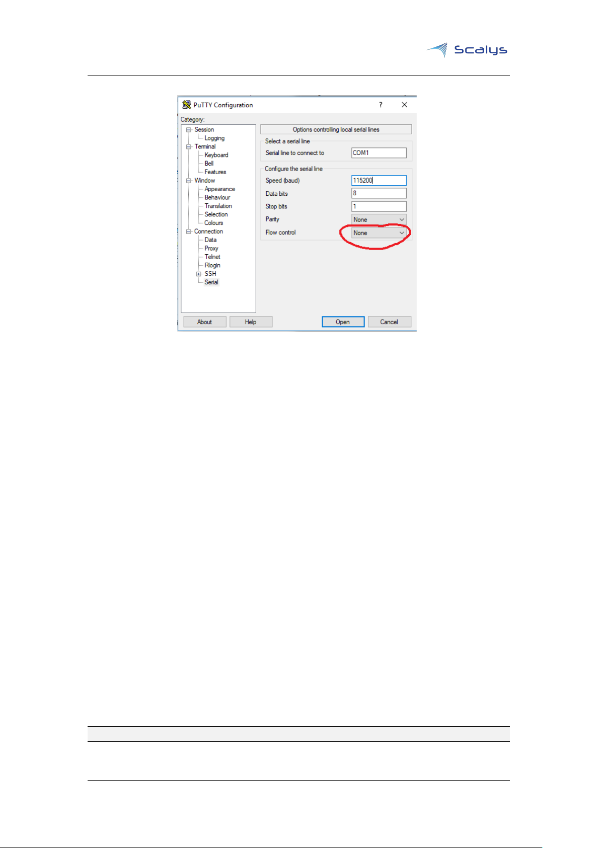
7.3 Why doesn’t my TrustBox seem to accept my commands on the serial
port?
As mentioned in subsection 7.2.1, make sure to have the correct serial settings and ensure that
you have flow control set to none. For instance, in PuTTY you can achieve this as shown in figure
7.1 below.
Copyright © 2019, Scalys BV Restricted 17
Chapter 7. Frequently asked questions www.scalys.com
Figure 7.1: Flow control setting in PuTTY
7.4 Why doesn’t my TrustBox produce any output data on the serial
interface?
Firstly make sure you have the correct power supply for the TrustBox, or else it might not boot
fully. Even though the green power LED is lit it might not be enough for all the interfaces on the
TrustBox. Refer to the TrustBox User manual for specific information on the power supply.
Next we should also rule out any problem with the serial interface configuration. Refer to
subsection 7.2.1 for more information.
One last option would be to verify that the rescue boot mode doesn’t produce any output either.
Refer to section 5.3 on how to achieve this. If this works then try reprogramming the primary flash
from this rescue boot.
If none of these steps work then contact Scalys to resolve your issue.
7.5 The ethernet interfaces of the PFE are not working?
The
PFE
on the LS1012A processor requires firmware to operate. For U-boot it requires the ’pfe_fw_-
sbl.itb’ image (see section 5.2 on how to program it) and under Linux the ’ppfe_class_ls1012a.elf’
and ’ppfe_tmu_ls1012a.elf’ files in the ’/lib/firmware/’ directory. These files can be retrieved from
the
LSDK
github page[6].
before booting a Linux kernel
of the TrustBox.
Note that it is required to execute the command ’pfe stop’ in U-boot
. This has already been included for the default boot command(s)
7.6 Bluetooth can’t find any devices?
The default bluetooth kernel driver doesn’t initialize the RF-component of the combined WiFi/BT
module properly. You first need to initialize it through the WiFi driver, e.g.:
ifconfig <wlxXXXXXXXXXXXX> up
Copyright © 2019, Scalys BV Restricted 18

Chapter 7. Frequently asked questions www.scalys.com
7.7 PPA related kernel crash
Note that the LSDK kernel expects a valid ppa firmware to be available to boot succesfully. You
can generate a default LS1012A ppa binary in the LSDK flexbuild environment using:
flex-builder -c ppa-generic -m trustbox
You can then find the binary under build/firmware/ppa/soc-ls1012/ppa.itb, which may be programmed in the primary flash under U-boot.
Copyright © 2019, Scalys BV Restricted 19

BSP User guide
www.scalys.com
May 29, 2019
A
References
[1]
SDK QorIQ online manual. [Online]. Available: https://nxp.sdlproducts.com/LiveContent/web/pub.xql?c=
t&action=home&pub=QorIQ_SDK&lang=en-US
[2]
LSDK online manual. [Online]. Available: https://nxp.sdlproducts.com/LiveContent/web/pub.xql?c=t&
action=home&pub=LSDKUG_Rev19.03&lang=en-US
[3]
QorIQ©Layerscape 1012A Low Power Communication Processor. [Online]. Available:
https://www.nxp.com/products/processors-and-microcontrollers/arm-based-processors-and-mcus/
qoriq-layerscape-arm-processors/qoriq-layerscape-1012a-low-power-communication-processor:
LS1012A
[4] Yocto project. [Online]. Available: https://www.yoctoproject.org/
[5]
NXP supporting information on LSDK in comparison to QorIQ Linux SDK, 2018. [Online]. Available:
https://www.nxp.com/docs/en/supporting-information/DN-LSDK-Introduction.pdf
[6]
Layerscape Software Development Kit download link (requires registration. [Online]. Available: https://www.
nxp.com/support/developer-resources/run-time-software/linux-software-and-development-tools/
layerscape-software-development-kit-v19.03:LAYERSCAPE-SDK?tab=Design_Tools_Tab
[7] Layerscape Software Development Kit github page. [Online]. Available: https://lsdk.github.io/
Copyright © 2019, Scalys BV Restricted 20

www.scalys.com
B
List of Acronyms
BSP User guide
May 29, 2019
BSP Board Support Package
LSDK Layerscape Software Development Kit
PBI Pre-Boot Instructions
PBL Pre-Boot Loader
RFS Root File System
RCW Reset Configuration Word
SDK Software Development Kit
PFE Packet Forwarding Engine
PPA Primary Protected Application
Copyright © 2019, Scalys BV Restricted 21
 Loading...