

Page 1

Getting Started
D7-180
D7-180XR
Page 2

Scallop Imaging’s 7 megapixel video surveillance cameras are
the first stand-alone computational imaging systems. The
imaging task is distributed among five powerful microsensors.
The camera’s embedded CPUs synthesize the image data into
one seamless 180° field of view. The embedded web server
will service connection requests and provide clients two
simultaneous video streams:
• A standard 15 fps HD frame comprised of a 1280 x 320
situational awareness (SA) window plus a 1280 x 400 sub
window allocated to up to four detail windows;
• 5120 x1280 full resolution stream at 1 fps.
TABLE OF CONTENTS
Connecting the Camera .................................2
Installing the Camera......................................3
Installing the Software....................................4
Minimum System Requirements .....................4
Accessing the Camera....................................5
Live Feed ..........................................................7
Selecting Zoom Window views .......................7
Video Recording..............................................9
Camera Settings ...........................................10
Users List.......................................................10
Network Settings...........................................11
Protocol Settings...........................................12
Recording Settings........................................13
Imaging Settings ....................................14—18
Date and Time ...............................................19
Error Log........................................................19
Status LED.....................................................19
Firmware........................................................20
System Overview...........................................20
Standard Terms and Conditions for Sale ..21
Specifications.................................................24
1
Page 3
2
Connecting the Camera
You can set up and operate the D7-180 and D7-XR Cameras using a
standard JavaScript-enabled browser on Windows 7 or Windows 8.
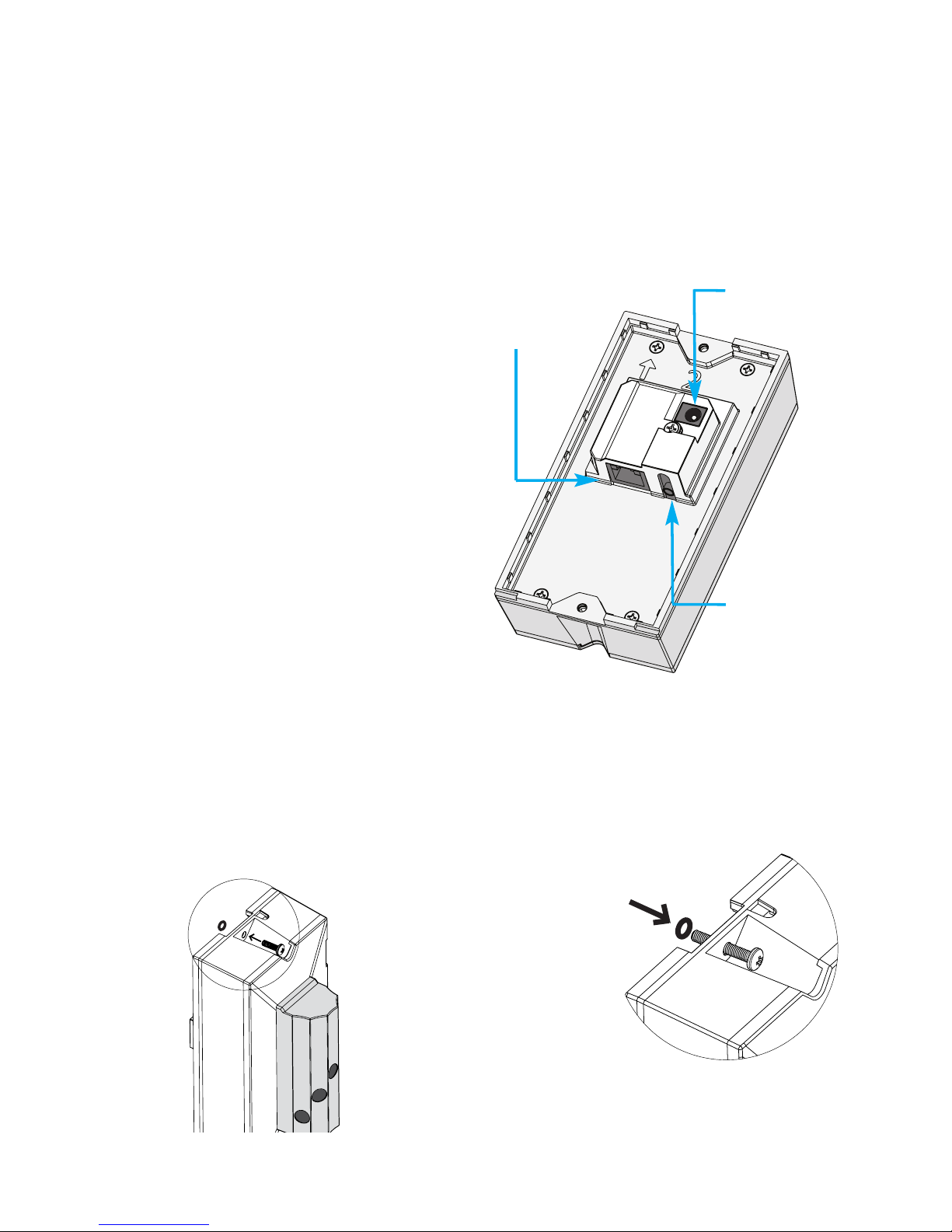
PoE Operation
The camera can be connected
over a network by a CAT-5 Ethernet cable plugged into the rear of
the camera. If the network supports PoE, power is supplied directly via the Ethernet cable. The
camera can also be powered by
a 12volt power supply that is included if the network does not
support PoE.
Ethernet
connection
12V DC plug
Audio
connection
(not yet supported)
Two O-rings have been
included to aid in
installations, if needed.
The O-rings are intended to
secure the screws before
attaching the camera to
the wall mount. Insert the
screw into the mounting holes
at the top and bottom of the camera. Rolling the
O-ring over the tip of the screw will hold it in
place allowing for easier installation.
Page 4
3
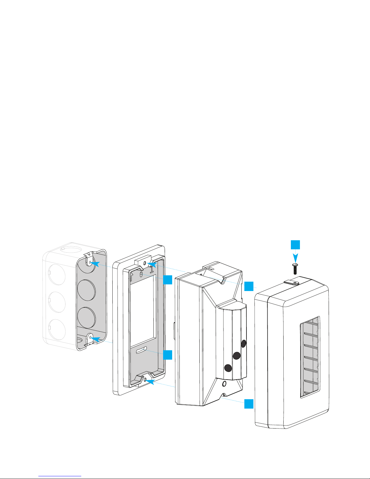
Installing the Camera
A. Place the flush wall mount bracket (1) against a gang box and at-
tach top screw, leaving screw slightly loose.
B. Attach the bottom screw.
C.Using a bubble level, level the mounting bracket, then finish tight-
ening both screws.
D.Feed the Ethernet cable through hole of mounting bracket, and
connect to the Camera (2).
E. Place the camera on the mounting bracket, and secure with pro-
vided screws.
F. Slide the camera cover (3) over the camera and secure with pro-
vided tamper-proof screw.
Note: Do not overtighten or use power tools when attaching
wall mounts.
Junction
Gang Box
Flush Wall
Mount (1)
Camera (2)
Camera Cover (3)
B
E
F
A
E
Page 5
4
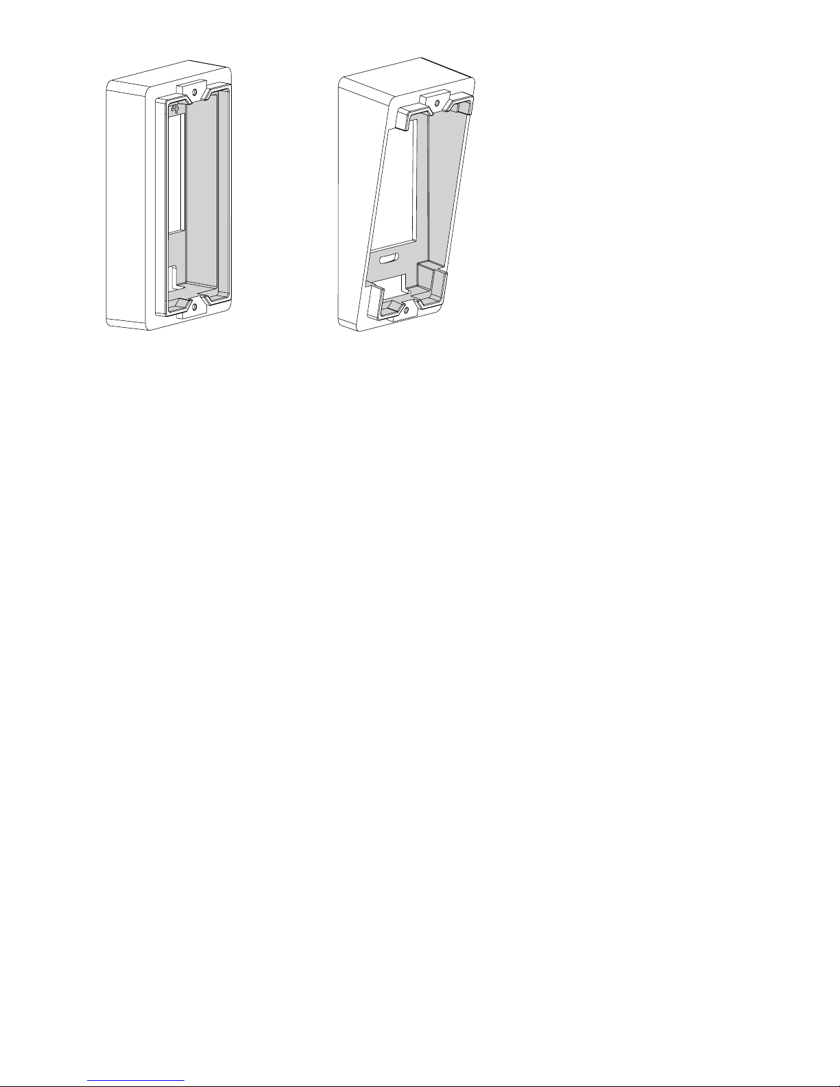
If no Junction Gang Box
is available, the Vertical
Wall Mount (4) for
straight ahead viewing,
or the Angled Wall
Mount (5), for angleddown viewing may also
be mounted flush to the
wall.
Be sure to use appropriate wall anchors (not
included) to secure the
mount to a drywall
surface.
Vertical Wall Mount Angled Wall Mount
Accessories: alternative mounts
Installing the Software
On a network
In order to get the camera operating on a network, software will need to
be installed on a computer that meets the minimum system requirements.
Minimum System Requirements:
• Windows 7 or Windows 8
• 2.0 GHz CPU (Dual-core
1.8GHz or higher CPU
with 2 GB RAM or higher
recommended)
• 2 GB RAM or higher
• 200 MB hard drive space
• Display adapter capable of 32-
bit color depth or higher,
512 MB or higher video
memory
• Minimum display resolution
1280 x 720
• 10/100 Mb Ethernet adapter
• PoE Switch or 12V DC power
supply (included)
• Internet Explorer or Mozilla
FireFox
Page 6

5
Software installation
It is necessary that you register your camera as soon as possible at
scallopimaging.com/registration
so that you can download and
install the D7-180 Software Installation Driver files.
It is critically important that you download and install these
drivers before operating the camera. The camera will not operate without installing these files on your computer.
All registered users will be able to remotely download and install all
future camera software upgrades at no charge from the
scallopimaging.com website. We can notify you when future software
enhancements become available.
Accessing the Camera
On a network
Scallop Imaging IP cameras are IPV4LL compliant. If you have a DHCP server
on your network, the DHCP server “router” will assign the camera an IP address automatically. If a DHCP server “router” is not on the network, the camera will be assigned a 169.254.x.x address. If you are setting up the camera
without a DHCP server “router” you will need to set your computer to obtain
and IP address.
Examples:
Established network:
1. Set laptop to obtain an IP address automatically.
2. Connect and power all devices.
3. Cameras will show in camera finder with individual 169.254.x.x addresses.
Laptop. Multiple Scallop cameras, PoE switch:
1. Set laptop to obtain an IP address automatically.
2. Connect and power all devices.
3. Cameras will show in camera finder with individual 169.254.x.x addresses.
Page 7
6
Once you access the camera you
can change its mode from DHCP to
Static. See the network settings section for more detail.
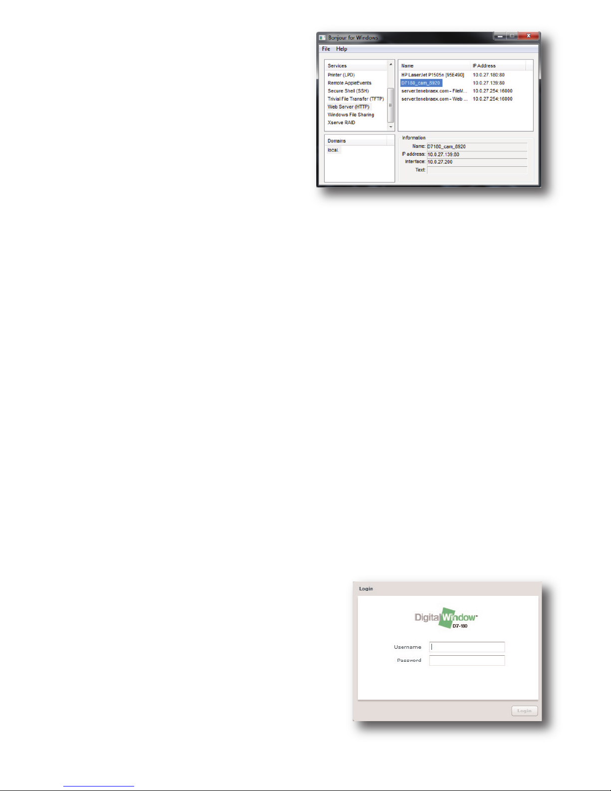
Also provided is a Bonjour for
Windows discovery utility.
This stand-alone program has been
provided for easy access to the
camera.
To use it, simply start the application and a window (above) will appear.
Click on Web Server (HTTP) on the left column and devices with the
Bonjour naming protocol will be shown on the right hand column. Each
D7-180 camera will be named “D7180_cam_****”, and each D7-180XR
will be named “D7XR_CAM_****.” The **** will be the last 4 digits of the
MAC address of the camera. The MAC address can be found printed
on the rear label of each camera.
Note: The Bonjour networking protocol sends and receives network packets on UDP port 5353. The Bonjour installer will configure
the Windows firewall appropriately during installation on supported systems, but if you have a separate "personal firewall" enabled, you will
need to ensure that UDP port 5353 is open for Bonjour to work correctly. The Bonjour for Windows discovery utility is subject to change.
Once you have found the camera in the Bonjour for Windows program
simply click on its name and your default browser will open the camera's built-in web interface.
The first window that will appear will
be the login screen.
You can log on to the camera using the
default username and password.
• The default user name is: admin.
• The default password is: password.
Page 8
Live Feed Screen
After logging in, you will be brought to the
D7-180/D7-180XR browser site. By default,
the “Live Feed” tab will be activated
If your browser has multiple tool bars open,
and the display resolution is close to the minimum system requirements, the bottom of the
live view page will be cut off.
To obtain the full view of the camera and to avoid scrolling, set the
browser to full screen mode. This can be done by clicking "view" then
clicking full screen, or pressing F11 on the keyboard.
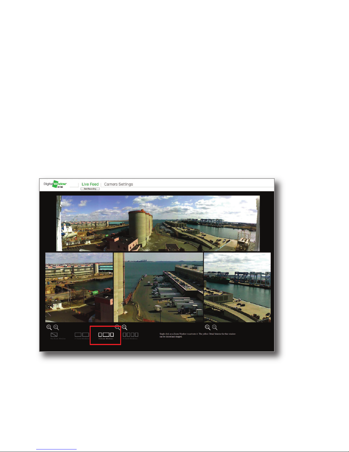
Selecting Zoom Window Views
At the bottom of the page you will find options to configure the zoom
windows. You can choose 0, 2, 3 or 4 zoom windows to appear on the
screen at once.
7
Once you initially log
on to the camera, you
can set up user
accounts.
Setting up user
accounts is discussed
in more detail later in
The Camera Settings
section on page 10.
Page 9

8
To choose the number of zoom windows you
would like to appear on the screen click on
the icons at the bottom of the screen. Once
chosen the video will change to the zoom
window configuration you have choosen.
Positioning the
zoom windows:
Click on the zoom
window in the bottom
half of the live feed
window that you wish
to reposition. Once
you have clicked in
the desired zoom
window a yellow box
will appear in the Situational Awareness
Window (180 degree
view) where the current position of the zoom window is located (see
above):
Once the yellow box appears, you can drag the box to reposition it by
holding down the mouse button and dragging and dropping the box
to the position you want the zoom window to be positioned. Once you
release the mouse button, the zoom window will reposition to that location. Do this for each zoom window to obtain views of the area of interest. You can change the positions of the zoom windows anytime.
Live Feed Screen (continued)
Note: The video will
stop playing for 2-3
seconds while the new
zoom windows appear.
Page 10

9
Video Recording
At the top of the screen under the Live Feed tab you will also find a
"Start Recording" button.
Video recording using the web browser interface will save an .flv file to
your computer and before recording is started, you will be prompted
to set the location and name of the file to be saved. Choose your location and click OK.
Once recording starts, you will see a progress bar appear next the
recording button with a percentage of completion. If the user needs
to stop the recording for any reason, click the stop recording button
and the recording will write an .flv file up until the stop button is hit.
Recording can be setup to run from 1 minute to continuous recording
under the Recording tab under Camera Settings.
Page 11

10
Camera Settings
Under the Camera Settings tab, administrators will be able to access
the following options: Users, Network Setup , Protocol, Recording, Imaging, Date and Time, Error Logs, Status LED, Firmware, and System
Overview.
Users List
Once you click the Add User button on the right hand side the window
to the right will appear. Here you may
add new users by entering the user
name, password, full name, the role
the user will perform and the option of
enabling the user to access and modify the camera setting.
The Admin role will give full access
to the camera setting and the Viewer
role will have only the option to view
the stream and modify the zoom
positions.
Other options on this tab is Editing and Removal of added users. Once
user have been added and the users “Admin or Viewer” have logged in
you will be able to see an overview of the last log in time and date.
Page 12

11
Network Settings
In the Network Settings tab
you have the option to
change how the camera will
function on the network.
In some situations the user
may desire to change the
camera into Static mode
(Manual) to match the existing
network. To do this click the Manual Configuration mode and enter
the IP Address, Subnet mask, default gateway and any preferred and
alternative DNS if needed.
Once you have entered the information of your network, click the
SAVE SETTINGS button. When this button is clicked, close your
browser, reopen in a new browser window, and enter the new IP address that you have assigned to the camera.
Note: Take care to enter the information accurately. If the information has been entered incorrectly, and the camera is not accessible
with the data the user has supplied, you will need to use a crossover
cable to access the camera again. This is done by connecting the
camera directly to your computer via a crossover cable and changing
the computer’s IP address to static mode. For more information with
this type of connection please contact your System Administrator.
Page 13

12
Protocols Settings: SMTP, UPnP, and Bonjour
SMTP settings:
In the SMTP settings, you can add
your email's SMTP
settings and email
address to send any
error logs created by
the camera. If problems occur with your
camera these logs can be sent to email addresses for troubleshooting purposes. You will need to obtain the hosting IP address from
your email provider or your system administrator.
Bonjour
The camera also includes the
Bonjour protocol, This feature is
enabled by default, and is used in
the initial setup of the camera.
Bonjour by Apple, also has plugins for Internet Explorer and Firefox that can be down-loaded from
the internet.
Camera Settings (continued)
Page 14

13
Recording Settings
The D7-180/D7-180XR camera has a recording function that allows
you to record video from the camera. You can set this up by selecting
the Camera Settings tab, and clicking on the Recording tab.
This will bring you to the Recording settings Page, where you can set
the recording time, the filename of the recording, and which video
streams you would like to record.
Click OK to save
your settings, and
then click on the Live
Feed tab. When you
want to start recording, click on the Start
Recording button.
The video will be
recorded fo the time
you have set, or if
you have chosen to
record continuously,
it will record until it runs out of hard drive space. For recording sessions where the size of the video exceeds the maximum file size allowed by Windows, the application will create multiple files where a
number will be appended to the filename that you have set in order to
create unique filenames and prevent overwriting the recordings. For
each new file, the filename will be incremented by 1. The videos are
stored in .flv format.
While the camera is recording, the Start Recording button on the Live
Feed page will transition to a Stop Recording button with a progress
bar that shows percent completion of the recording session that you
have setup. If you would like to stop recording at any time, press the
Stop Recording buton,and recorded video will be saved until the time
that you stopped the recording.
Page 15

14
Imaging Settings
The camera’s Imaging Settings has multiple functions that the user can
use to obtain the best picture quality for each camera location that
may have unique lighting characteristics.
The Imaging Settings has 5 sections: General, Contrast, Sharpening,
Video Quality and Advanced.
General:
Brightness Control
The camera utilizes autoexposure that is optimized for average scenes.
If the live video appears either too bright or too dark, you can adjust
the autoexposure brightness target by adjusting the slider to darker or
brighter settings. Once you have set the desired brightness, click the
Save Settings button at the bottom of the tab.
Camera Settings (continued)
Page 16

15
Autoexposure Mode
The camera supports two different modes of
autoexposure: Average and Independent. The
Average mode measures light levels over the
entire field of view and calculates a fixed exposure for the entire 180° field of view. Average mode is good for most scenes.
The Independent mode of autoexposure allows each image sensor to
set its own best exposure. Independent mode is best for scenes with
very high dynamic range. The Autoexposure mode can be set by
clicking on the button adjacent to the desired exposure mode.
White Balance
The camera supports both auto white balance and manual white balance. Auto white balance is the best choice for most scenes. If the
scene has mixed lighting or very unusual lighting conditions, setting
the white balance manually may result in a better looking image.
In Manual White Balance mode, the color channel gains can be set
manually by clicking in each of the boxes adjacent to the R, G, and B
channels and entering a value between 100 and 200. Entering higher
values for channel gains makes the color channel more intense.
Note: In order for you to see the color changes you will need to
enter the desired value into each color then click to the next
color. If the cursor is still in the box being modified the color will not
change until you move to the next. If a value is entered outside of the
100 to 200 range the box will turn red until a number fitting that range
is entered.
Once you have
changed the settings
to your liking, click
“Save Settings” and
your settings now
become the default
values.
Page 17

16
Max Exposure Time
The max exposure time control sets the maximum exposure time that
the camera’s autoexposure system can take. If there are moving objects close to the camera, you may need to make the maximum exposuretime shorter to control motion blur. Conversely if the scene is
very dark and objects are far away from the camera or not moving
rapidly, you may get better low light performance if the maximum exposure time is set to be longer.
Please note that when the maximum exposure is longer than the
frame rate, the frame rate will be adjusted to correspond to the maximum exposure until conditions change. If the maximum exposure is
shorter than the frame rate, the frame rate will remain unchanged.
Custom Overlay
You can specify a text string that can be overlaid on the video by
checking the Display Custom Overlay box and typing the text into the
box below the check box.
Sharpening
The Sharpening tab allows you to adjust the sharpness of the image.
Camera Settings (continued)
Page 18

17
Band Filter
The band filter is used when the lighting has
temporal modulation, such as many fluorescent lights. For many fluorescent lights the
video will show banding artifacts that come
from the lighting modulation. The artifacts can
be eliminated by enabling the banding filter
that will adjust the exposure of the camera to
avoid these artifacts. The 60 Hz filter should
be chosen for lights with 60 Hz power modulation. The 50 Hz filter should be chosen for
lights with 50 Hz power modulation.
Date/Time Overlay
The camera can display a date and time overlay on the video feed.
The position of the overlay can be set using the drop down menu.
There is also the feature that a custom text string can be added to
the overlay by selecting the custom text option, and typing in the desired text.
The camera is shipped
from the factory with
default setitings.
Clicking the “Restore
Factory Settings”
button will overide any
changes you may have
made and revert to the
original default settings
for that particular
Image Settings tab.
Page 19

Contrast
There are four contrast curves that can be selected to enhance the
video quality for various lighting conditions. For most scenes, the
None (Linear) setting yields the best result. The Shadow Detailed
curve is good for dark scenes and enhances details in dark areas.
The Low Contrast curve increases the contrast for scenes with low
dynamic range. The High Contrast curve diminshes the contrast for
scenes with very high contrast.
Video Quality
The Video Quality tab allows the video compression quality and frame
rate to be adjusted. The frame rate of the 720p video stream can be
adjusted from 1 to 15 frames/sec. Video Image Quality changes the
compression ratio of the video. The Low quality setting results in the
highest amount of compression, smallest file size and lowest bandwidth requirements for the
camera. The High
quality setting results in the lowest
amount of compression, and a
larger file size and
higher bandwidth
requirements.
Advanced
The Advanced tab allows you to adjust the alignment of the image
sensors, and to restore all factory imaging settings.
18
Camera Settings (continued)
Page 20

19
Image Alignment
The camera is set up at the factory with image sensor alignments optimized for average distances. If the camera is installed in an area
where there are objects closer to the camera or much further away,
you may need to adjust the sensor alignments so that the video is
seamless.
A live view of the video is displayed in the Advanced tab. The format
of the video shows four zoom windows positioned to show the seam
where two sensors meet in the center of the zoom window to aid in
aligning the
seams.
There are four
seams between
image sensors
where the imagery needs to
be aligned. For
each seam,
there are four
control arrows
that can be used
to adjust the
image alignment. The up and down arrows allow you to move the
image to the left of the scene up and down to align it to the adjacent
image. The arrows pointing left and right allow you to adjust the
amount of overlap between adjacent images. If you would like to adjust the alignment of the imagery at a seam, click on the seam’s flag
to activate it, and make adjustments. The seam that is active is highlighted in green.
If you would like to restore all of the factory image settings, click on
the Restore All Imageing Settings button. This will restart the camera
with all of the imaging settings restored.
Page 21

Date and Time
In the Date and Time tab you can set the time to 24h or 12h standards. You can also click the use local time button and the camera
will configure itself to the time of your computer.
Note: When clicking the Use Local time and then clicking Save settings, the camera will produce a popup with a countdown for the
camera to restart. This is done to get “RTC” (Real Time Clock) to
store into the hardware of the camera. Once the countdown is complete, you will be brought back to the login screen of the camera.
Error Log
In the Error log tab you can modify how error logs are sent to you,
You can choose critical, warnings, information or all to be emailed
to you on a regular basis. They can be sent daily, weekly or monthly
mailing intervals.
The recipient email address is based on the information setup in the
SMTP protocol tab.
You may also view the log here by clicking View Log. A pop up
screen will appear with the log inside. You can copy and paste this
log into an email and send it to Scallop Imaging if there is an issue
that needs technical support.
Status LED
On the front of the camera, is a bright green Status LED. You have
the ability to turn this light on and off depending on your requirements. Once the modification has been made click Save Settings.
20
Camera Settings (continued)
Page 22

21
Standard Terms and Conditions of Sale
Scallop Imaging, LLC D7-180 and D7-180XR Digital Camera
Limited Warranty
1. Standard Limited Warranty. Standard terms and conditions of sale are available on
Scallop Imaging’s website www.scallopimaging.com.
Page 23

SPECIFICATIONS D7-180 AND D7-180XR CAMERA
Camera:
Image Device (5) 1.3 Mpixel CMOS
Number of effective
pixels 6,553,600 pixels
Shutter Electronic rolling shutter
Gain Control Automatic gain control
Exposure control Average, 5 zone independent
Depth of Field 1 ft. to infinity
Minimum illumination D7-180: 3 lux at 10 fps
D7-180XR: 0.5 lux at 8 fps
Image:
Image size (HxV) 2 simultaneous video streams:
• A standard 15 fps HD frame comprised of a
1280 x 320 situational awareness (SA) window
plus a 1280 x 400 sub window allocated to up to
four zoom windows;
• 5120 x1280 full res stream at 1 fps
22
Specifications
2.49”
63mm
.25”
6mm
Single Gang
Box
3.28”
83mm
3.14”
80mm
5.72”
145mm
.85”
22mm
Side view Front view
Page 24

23
Field of view 180º x 48º
28 pixels per degree of field of view
Image resolution Everywhere within the field of view equivalent to
resolution of a 1.3 MP camera with a 33.7mm lens
Compression H.264
Maximum frame rate 15 fps for SA and zoom, 1 fps for full res window
Compression ratio User selectable
Bandwidth requirements1using H.264
at Medium quality compression:
HD Window: At 15 fps, less than 2.0 Mbit/sec
Full Resolution Image: At 1 fps, less than 1 Mbit/sec
1
Bandwidth requirements are scene dependent. Your results may vary.
Audio:
Audio in/out with firmware upgrade
Network:
Protocols TCP/IP, HTTP, SMTP, DHCP, RTP/RTSP,
DNS, BONJOUR
Interface Internet Explorer, Firefox
Interface:
Ethernet 10Base-T/100Base
COMM ports Ethernet
General:
Weight 9 oz. (255 g)
Dimensions (WxHxD) 3.28 x 5.72 x 2.49 inches (83 x 145 x 63 mm)
Power requirements 48V PoE, 12V DC
Power consumption < 7 W
Operating temp. -40ºF to 140ºF (-40°C to 60°C)
Storage temperature -40ºF to 185ºF (-40°C to 85°C)
Supplied Accessories:
Surface Mount
Flush Mount
Angle Mount
Page 25

www.scallopimaging.com
© 2014 Scallop Imaging, LLC Specifications subject to change without notice
20140220 DW01-600-033-RevD
U.S. Patent No.: 7,262,789 and additional U.S. and international patents.
 Loading...