

Page 1
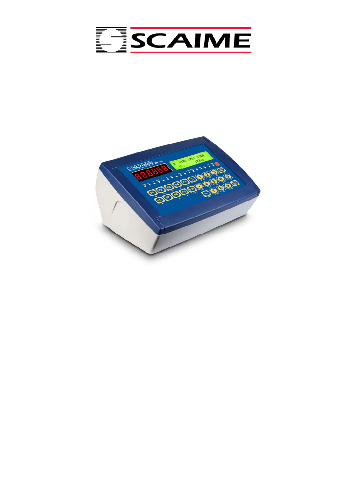
IPE100
CUSTOMER/PRODUCT/VEHICLES DATABASE
SCAIME SAS
Technosite Altéa - BP501
74105 Annemasse - France
Tel. (+33) 4 50 87 78 64
Fax. (+33) 4 50 87 78 46
[email protected]
www.scaime.com
IN/OUT WEIGHING WITH
USER MANUAL
NU-IPE100-IO-USER-E-0212
Page 2

IPE100 indicator NU-IPE100-IO-USER-E-0212
INDEX
1. INTRODUCTION ................................................................................................................................................................. 5
2. MAIN TECHNICAL SPECIFICATIONS ............................................................................................................................... 6
2.1 ACCESSORIES AVAILABLE ....................................................................................................................................... 7
2.2 SYMBOLS USED ......................................................................................................................................................... 7
3. INSTALLATION .................................................................................................................................................................. 8
3.1 IPE100 CASE AND DIMENSIONS ............................................................................................................................... 8
3.2 POWER SUPPLY ......................................................................................................................................................... 9
3.3 START UP.................................................................................................................................................................... 9
3.4 TURNING OFF THE INSTRUMENT ............................................................................................................................ 9
3.5 TURNING ON PRINTER IN ENERGY SAVING MODE ............................................................................................. 10
4. FRONT PANEL KEYS AND DISPLAYS ........................................................................................................................... 10
4.1 FUNCTION OF THE KEYS ........................................................................................................................................ 10
4.1.1 "2ndF" KEY: SECOND FUNCTION OF THE KEYS ........................................................................................ 11
4.1.2 ENTERING ALPHANUMERIC TEXT ............................................................................................................... 12
4.1.3 DISABLING THE KEYBOARD ......................................................................................................................... 12
4.1.4 HELP MENU .................................................................................................................................................... 13
4.1.5 INDICATOR CONNECTED TO PC KEYBOARD ............................................................................................. 13
4.1.6 REMOTE CONTROL ....................................................................................................................................... 14
4.2 FUNCTION DISPLAY ................................................................................................................................................. 16
4.2.1 STATUS INDICATORS ................................................................................................................................... 16
4.2.2 BATTERY LEVEL INDICATION ...................................................................................................................... 18
4.2.3 "TILT" DEVICE ................................................................................................................................................ 18
4.2.4 DISPLAYED DATA .......................................................................................................................................... 18
5. SELECTION OF THE SCALE ........................................................................................................................................... 19
5.1 FUNCTIONING WITH REMOTE SCALE ................................................................................................................... 20
5.2 “A+B” FUNCTION ....................................................................................................................................................... 20
5.3 WEIGHING WITH TWO SCALES: SELECTING INPUT/OUTPUT SCALES .............................................................. 20
6. SCALE ZERO FUNCTION ................................................................................................................................................ 21
6.1 CYCLICAL AUTOMATIC ZERO ................................................................................................................................. 21
7. TARE FUNCTIONS ........................................................................................................................................................... 21
7.1 SEMIAUTOMATIC TARE ........................................................................................................................................... 21
7.2 PRESET TARE .......................................................................................................................................................... 21
7.3 MANUAL CALCULATED TARE ................................................................................................................................. 21
7.4 TARE CANCELLATION ............................................................................................................................................. 21
7.5 LOCKED / UNLOCKED TARE ................................................................................................................................... 22
7.6 LIMITATION OF THE TARE FUNCTIONS ................................................................................................................. 22
7.7 TARE EXECUTION MODE OR DISABLING OF THE TARE ..................................................................................... 22
7.8 LINKING A PRESET TARE TO A VEHICLE IN THE DATABASE.............................................................................. 22
8. MULTIPLE RANGE AND MULTI-INTERVAL FUNCTION ................................................................................................ 22
9. DISPLAY OF METROLOGIC DATA (inFO) ..................................................................................................................... 23
10. FILLING IN THE INPUT TEXT ........................................................................................................................................ 23
10.1 QUICK MODIFICATION OF AN INPUT TEXT ......................................................................................................... 23
11. DATABASE .................................................................................................................................................................... 24
11.1 CUSTOMERS .......................................................................................................................................................... 24
11.1.1 ENTRY .......................................................................................................................................................... 24
11.1.2 MODIFICATION ............................................................................................................................................. 24
11.1.3 CANCELLATION ........................................................................................................................................... 25
11.1.4 PRINTING ..................................................................................................................................................... 25
11.1.5 SELECTION / DESELECTION ...................................................................................................................... 25
11.1.6 ENTRY, MODIFICATION AND QUICK SELECTION OF CUSTOMER 000 .................................................. 26
11.1.7 ALPHABETICAL RESEARCH ....................................................................................................................... 26
11.1.8 HELP ............................................................................................................................................................. 26
11.2 MATERIALS ............................................................................................................................................................. 27
11.2.1 ENTRY .......................................................................................................................................................... 27
2
Page 3

IPE100 indicator NU-IPE100-IO-USER-E-0212
11.2.2 MODIFICATION ............................................................................................................................................. 27
11.2.3 CANCELLATION ........................................................................................................................................... 28
11.2.4 PRINTING ..................................................................................................................................................... 28
11.2.5 SELECTION / DESELECTION ...................................................................................................................... 28
11.2.6 ENTRY, MODIFICATION AND QUICK SELECTION OF MATERIAL 000 ..................................................... 29
11.2.7 ALPHABETICAL RESEARCH ....................................................................................................................... 29
11.2.8 HELP ............................................................................................................................................................. 29
11.3 VEHICLES................................................................................................................................................................ 30
11.3.1 ENTRY .......................................................................................................................................................... 30
11.3.2 MODIFICATION ............................................................................................................................................. 30
11.3.3 CANCELLATION ........................................................................................................................................... 31
11.3.4 PRINTING ..................................................................................................................................................... 31
11.3.5 SELECTION / DESELECTION ...................................................................................................................... 31
11.3.6 ENTRY, MODIFICATION AND QUICK SELECTION OF VEHICLE 000 ....................................................... 32
11.3.7 ALPHABETICAL RESEARCH ....................................................................................................................... 32
11.3.8 HELP ............................................................................................................................................................. 32
12. DATABASE ACCESS PASSWORD ............................................................................................................................... 33
13. WEIGHING PROCEDURES ............................................................................................................................................ 33
13.1 GENERAL DESCRIPTION OF THE SYSTEM ......................................................................................................... 33
13.2 WEIGHING THROUGH ID CODE ............................................................................................................................ 33
13.2.1 INPUT WEIGH ............................................................................................................................................... 33
13.2.1.1 SINGLE VEHICLE ........................................................................................................................ 33
13.2.1.2 VEHICLE WITH TRAILER ............................................................................................................ 34
13.2.2 OUTPUT WEIGH ........................................................................................................................................... 35
13.2.2.1 SINGLE VEHICLE ......................................................................................................................... 35
13.2.2.2 VEHICLE WITH TRAILER ............................................................................................................. 35
13.3 WEIGHING THROUGH VEHICLE LICENSE PLATE ............................................................................................... 36
13.3.1 INPUT WEIGH ............................................................................................................................................... 36
13.3.1.1 SINGLE VEHICLE ......................................................................................................................... 36
13.3.1.2 VEHICLE WITH TRAILER ............................................................................................................. 36
13.3.2 OUTPUT WEIGHING .................................................................................................................................... 36
13.3.2.1 SINGLE VEHICLE ......................................................................................................................... 36
13.3.2.2 VEHICLE WITH TRAILER ............................................................................................................. 37
13.4 CONDITIONS FOR TOTALISATION........................................................................................................................ 38
13.5 ADDITIONAL TARE FUNCTION .............................................................................................................................. 38
13.6 TOLERANCE WEIGHING FIELD ............................................................................................................................. 38
13.7 REENABLING THE PRINTING AND INPUT / OUTPUT WEIGH ............................................................................. 39
13.8 VISUALISATION AND CLEARING OF THE ACCUMULATED TOTALS ................................................................. 39
13.9 PROGRESSIVES ..................................................................................................................................................... 39
13.9.1 PROGRESSIVE DIGITS ................................................................................................................................ 39
13.9.2 TICKET PROGRESSIVE ............................................................................................................................... 40
13.9.3 LOT PROGRESSIVE ..................................................................................................................................... 40
14. PRINTOUTS .................................................................................................................................................................... 40
14.1 LINKING OF THE FORMATS TO THE PRINT FUNCTIONS ................................................................................... 42
14.1.1 QUICK LINKING OF THE FORMATS ........................................................................................................... 43
14.2 NUMBER OF TICKET COPIES ................................................................................................................................ 43
14.3 REPETITION OF THE LAST EXECUTED PRINTOUT ............................................................................................ 43
14.4 STANDARD PRINTING FORMATS ......................................................................................................................... 43
15. OTHER FUNCTIONS ...................................................................................................................................................... 44
15.1 CALCULATOR ......................................................................................................................................................... 44
15.2 DISPLAY OF NET WEIGHT WITH SENSITIVITY X 10 (for testing use during calibration) ...................................... 44
15.3 SETTING DATE / TIME ............................................................................................................................................ 44
15.4 SET-POINT FUNCTION ........................................................................................................................................... 44
15.4.1 NORMAL FUNCTIONING MODE .................................................................................................................. 45
15.4.1.1 SETPOINT ON THE GROSS WEIGHT ......................................................................................... 45
15.4.1.2 SETPOINT ON THE NET WEIGHT ............................................................................................... 45
3
Page 4

IPE100 indicator NU-IPE100-IO-USER-E-0212
15.4.1.3 GROSS WEIGHT AT ZERO .......................................................................................................... 45
15.4.1.4 NET WEIGHT AT ZERO ................................................................................................................ 45
15.4.1.5 INSTABILITY ................................................................................................................................. 46
15.4.1.6 TOTALISATION ............................................................................................................................. 46
15.4.1.7 SETPOINT ON THE PARTIAL TOTAL .......................................................................................... 46
15.4.1.8 SETPOINT ON THE GENERAL TOTAL ........................................................................................ 46
15.4.1.9 SETPOINT ON THE GRAND TOTAL ............................................................................................ 46
15.4.1.10 SETPOINT ON THE NEGATIVE NET WEIGHT .......................................................................... 46
15.4.1.11 OPERATION MADE .................................................................................................................... 46
15.4.1.12 WEIGHT ACQUISITION .............................................................................................................. 47
15.4.1.13 CONTROL LIGHT ........................................................................................................................ 47
15.4.2 EXCLUSIVE FUNCTIONING MODE ............................................................................................................. 48
15.4.3 QUICK MODIFICATION OF THE SETPOINTS ............................................................................................. 48
15.5 DIAGNOSTIC PERIPHERALS ................................................................................................................................. 48
15.6 COM DATA DIAGNOSTIC ....................................................................................................................................... 49
16. ALIBI MEMORY .............................................................................................................................................................. 49
16.1 READING OF THE WEIGHS CARRIED OUT .......................................................................................................... 50
16.2 SERIAL COMMANDS FOR MANAGING THE ALIBI MEMORY:.............................................................................. 50
16.2.1 REQUEST WEIGHT VALUE WITH WEIGH ID .............................................................................................. 50
16.2.2 STRING FORMAT (WEIGHT/ID) ................................................................................................................... 51
16.2.3 WEIGH READING ......................................................................................................................................... 51
16.2.4 ALIBI MEMORY CANCELLATION (only with non approved instrument) ....................................................... 51
17. MESSAGES .................................................................................................................................................................... 52
17.1 INSIDE THE SETUP OR MENU OR AT START-UP ................................................................................................ 52
17.2 IN WEIGHING .......................................................................................................................................................... 53
DECLARATION OF CONFORMITY ..................................................................................................................................... 54
WARRANTY ......................................................................................................................................................................... 54
4
Page 5
IPE100 indicator NU-IPE100-IO-USER-E-0212
1. INTRODUCTION
This manual was created to help you install and learn all about the functional possibilities of the purchased indicator.
The instrument is suitable for use in various weighing environments.
Not only does it have all the normal features of high-precision scales, but it also gives you the possibility to work in specific
environments due to the functioning modes contained in the software implemented in the FLASH MEMORY on the internal
board; this makes the instrument extremely flexible and it can be used in many different industrial applications linked to
weighing. The double numerical and interactive alphanumerical display, the alphanumerical and function keyboard, allow
the operator an easy and immediate use and provide the microcontroller with DATA ENTRY functions in addition to the
normal weighing functions. The input/output allows the instrument to control various external devices, to receive external
commands, control a printer and communicate with a personal computer or to be inserted in a network of weight indicators
controlled by a PC.
WARNING
Please note that this instrument is covered by a warranty and MUST NOT BE OPENED BY THE USER for any reason
whatsoever. Any attempt to repair or modify the unit exposes the user to the risk of electric shock and will invalidate the
entire warranty.
If any problems are found in the unit or with the system in which it is used, the fact must be communicated to the
manufacturer or the dealer from whom it was purchased.
In any case, DISCONNECT THE POWER SUPPLY before taking any action.
The version with the 6V rechargeable battery has to be completely recharged (12 hours) in the first installation of
the instrument; we RECOMMEND disconnecting the battery if the instrument is not going to be used for more than
30 days. In order to avoid the deterioration of the rechargeable battery:
- In standard conditions, never leave the battery partially or completely uncharged; at least once a week recharge
it completely .
- In case the instrument is not used for a long period, one needs to:
1. completely recharge the battery before the system is switched off for the last time.
2. recharge completely every 3 months
Do not pour liquids on the weight indicator.
Do not use solvents to clean the weight indicator.
Do not expose the instrument to direct sunlight nor place it near heat sources.
Place or anchor the weight indicator and platform on a non-vibrating base.
All the connections of the indicator have to be made respecting the rules applicable in the zone and in the
installing environment.
Everything not expressly described in this manual has to be considered as improper use of the equipment.
Do not install in any area where there is a risk of explosion.
DO NOT exceed the rated capacity of the scale or of any load bearing element attached to the scale.
READ CAREFULLY AND APPLY WHAT IS DESCRIBED IN SECTION 3.
The crossed-out wheeled bin on the product means that at the product end of life, it must be taken to
separate collection or to the reseller when a new equivalent type of equipment is purchased. The
adequate differentiated refuse collection in having the product recycled, helps to avoid possible
negative effects on the environment and health and supports the recycling of the materials of which the
equipment is made. The unlawful disposal of the product by the user will entail fines foreseen by the
current regulations.
5
Page 6

IPE100 indicator NU-IPE100-IO-USER-E-0212
2. MAIN TECHNICAL SPECIFICATIONS
- 12 Vdc ( 8 ÷ 24 Vdc in the IO versions), with internal 100 ÷ 240 Vac (50÷60 Hz)
POWER SUPPLY
MAXIMUM POWER 16 VA.
OPERATING TEMPERATURE From -10 to +40 °C.
CONVERTER 24 bit Sigma Delta.
CONVERSION SPEED 200 conv./sec with automatic selection.
RANGE OF INPUT SIGNAL 0,6 mV/V - 3,2 mV/V.
MINIMUM VOLTAGE PER DIVISION
AUTOMATIC ZERO DETECTION Only in gross mode, programmable at +/- ¼, ½, 1, 2 divisions.
ZERO RANGE Configurable up to +/- 50% of max load capacity.
AUTO ZERO AT START-UP Configurable up to +/- 50% of max load capacity.
LOAD CELL POWER SUPPLY 5Vdc ± 5%, 120mA (max 8 350-Ohm cells).
LOAD CELL CONNECTIONS 6 wires with Remote Sense.
DISPLAY DIVISIONS
DISPLAYS
DATABASE/MEMORY
SIGNALS 16 status LEDs. Graphic icons on LCD display.
KEYBOARD
/ 12 Vdc adapter.
- 6 Vdc from fitted rechargeable built-in battery.
0.3 μV (approved instrument); 0.03 μV (non-approved instrument).
10000e, 3 x 3000e for legal for trade weighing, expandable up to 800.000 for
internal use (with minimum signal coming from the 1,6 mV/V cell).
- Red, high-luminosity LED indicators, with six digits (h 13 mm).
- Back lit graphic 160x32 dot LCD.
Database of 500 customers (3 descriptions of 25 characters).
Database of 500 materials (2 descriptions of 20 characters).
Database of 500 vehicles (plate of 10 characters, description of 20 characters,
linked tare).
Impermeable polycarbonate keyboard (IP65 protection degree), with membrane
keys with audible and tactile feedback.
PARAMETER SETUP
Calibration and linearity (up to 8 points), fully digital and programmable from the
keyboard or from PC with Scaletools
CLOCK/DATE Fitted, with buffer RAM.
SERIAL OUTPUTS
- 2 input/output RS232 ports on terminal board/ amp connector.
- 1 input/output RS485 port on terminal board or RS232 on amp connector.
- Management of PC keyboard
INPUTS AND OUTPUTS
- 2 optoisolated inputs (optoisolated photo couplers), 12Vdc – 24Vdc, 20mA max
- 4 outputs (optoisolated photomosfets), 48Vac / 0.15A, 60Vdc / 0.15A, 10 Ω
max.
6
Page 7
IPE100 indicator NU-IPE100-IO-USER-E-0212
2.1 ACCESSORIES AVAILABLE
On the indicator is possible implement internal and external modules used to increase interfacing possibilities.(For example,
the number of usable outputs various types of printers, in order to have a report of the weighs made, or giant display in
order to better see the weigh operations. Also, one can connect a PC in order to simply program the instrument through
Scaletools, or in order to have a complete management of the weighs.
Contact the reseller for the list of the available hardware and software accessories.
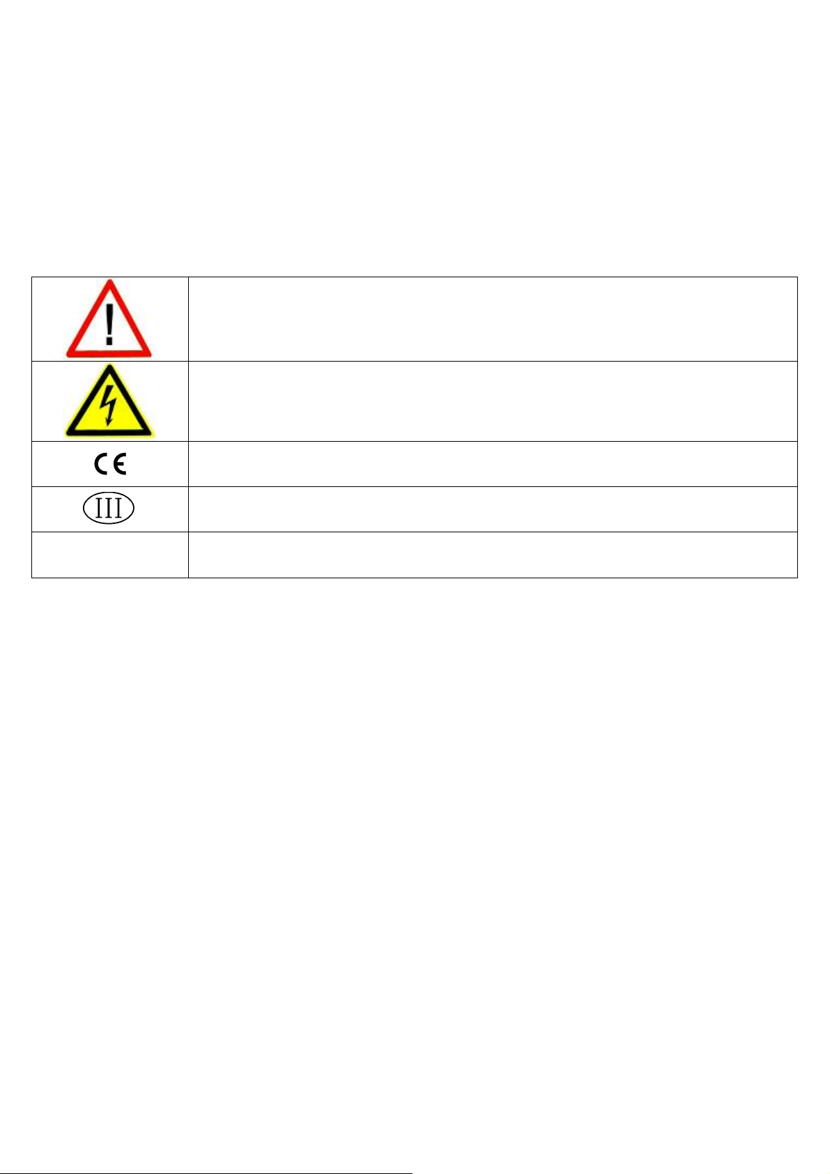
2.2 SYMBOLS USED
Below are the symbols or text used in the manual to recall the reader’s attention or on the instrument to recall the
user’s attention.
ATTENTION!
Only qualified personnel must perform this operation
ATTENTION!
This is referred to working on energized lines: only qualified personnel must require or perform
this operation.
CE CONFORMITY
IDENTIFIES THE CLASS OF PRECISION.
“TECHNICAL
MANUAL”
It means that an advanced function is being described (therefore for the technical personnel)
which will be further explained in the corresponding technical manual.
THE INSTRUMENT’S DANGEROUS VOLTAGE PARTS AND THE PARTS THE USER CAN ACCESS HAVE BEEN
ELECTRICALLY INSULATED.
7
Page 8
IPE100 indicator NU-IPE100-IO-USER-E-0212
3. INSTALLATION
3.1 IPE100 CASE AND DIMENSIONS
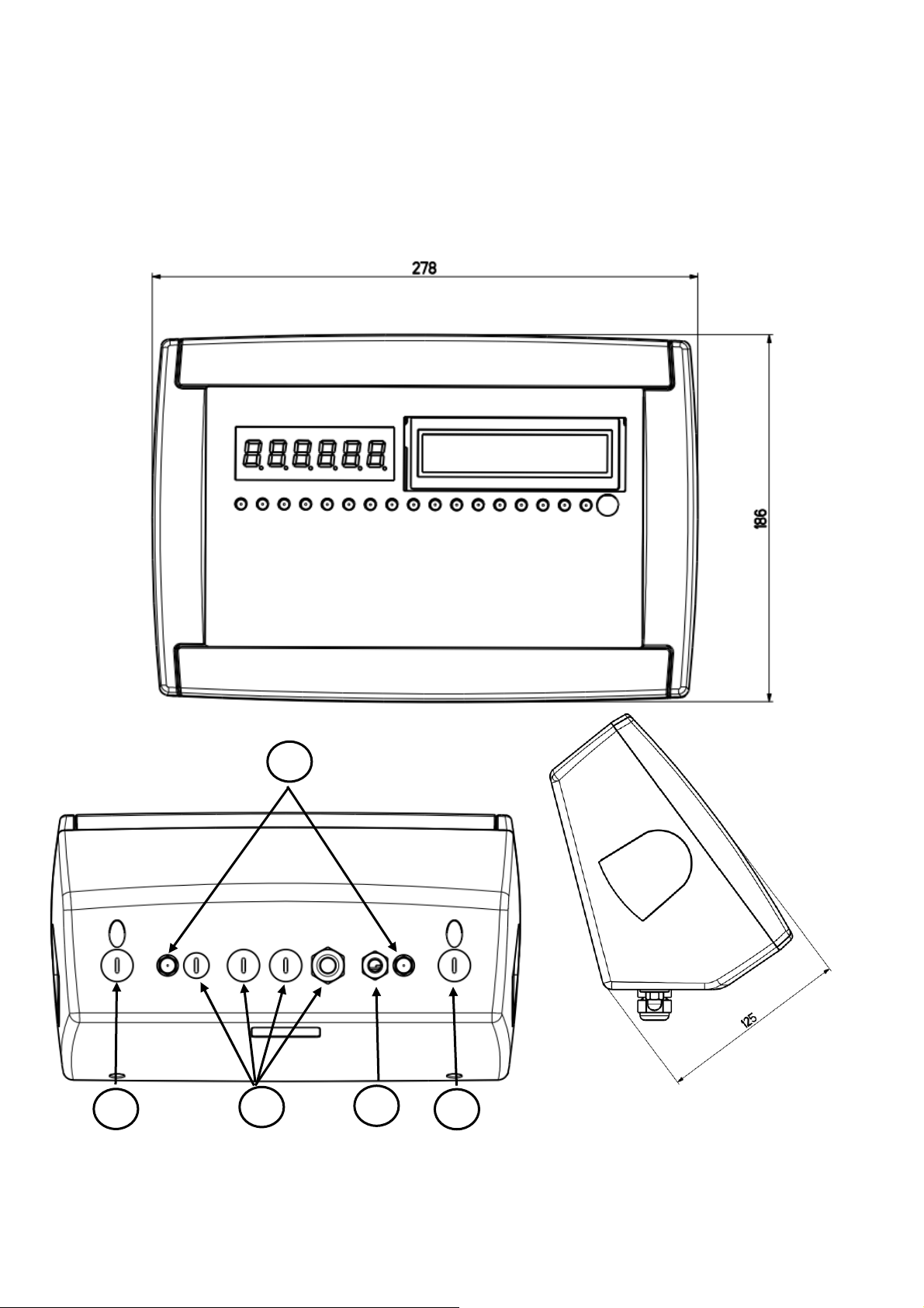
ABS MODEL
The indicator has an IP65 ABS case, whose external dimensions are shown in the Figure. It can be simply put on a table or
fixed to a shelf or column available on request.
NOTE: If the identification plate is supplied separately (therefore not attached to the indicator), it is advisable to
attach it to the indicator, in order to be able to identify the instrument.
2
1
3
4
Figure 2 – Measurements and dimensions in mm
1) RJ45 connector
2) Fixing for shelf or column mounting
3/5) Available for load cells / serial lines / inputs / outputs.
4) Power supply input.
5
8
Page 9

IPE100 indicator NU-IPE100-IO-USER-E-0212
3.2 POWER SUPPLY
- The IPE100 indicator is powered with 12Vdc voltage (8 ÷ 36 Vdc in the IO version), through an internal adapter which
converts the 100 ÷ 240Vac, 50÷60Hz mains voltage, and 6 Vdc, from the built-in battery (fitted depending on the model).
TO POWER the instrument through the 240 Vac mains, or TO RECHARGE the battery, insert the plug and the adapter to
the 240 Vac mains socket.
To connect the indicator to the power mains, the safety regulations must be observed, including the use of a "clean" line
without disturbances or interference caused by other electronic equipment.
The battery inside the indicator, lasts about 25 hours (without the expansion board, with 1-cell platform) and it needs a
recharging time of about 12 hours.
BATTERY FEATURES
Material LEAD
Power 4,5 Ah
Voltage 6 V
THE BATTERY MUST BE SUPPLIED DIRECTLY FROM THE MANUFACTURER.
NOTE: it is advisable to completely recharge it (12 hours) in the first installation of the instrument; we
RECOMMEND disconnecting the battery if the instrument is not going to be used for more than 30 days.
Do not connect other equipment to the same socket as the one that the adapter is in.
Do not step on or crush the power supply cable
3.3 START UP
TO TURN ON the IPE100 press the C key until the display turns on; then release.
The display shows:
- Initially a welcome message (settable in the TECHNICAL SETUP, << LoGo >> StEP, TECHNICAL MANUAL) while the
instrument carries out a series of checking and preheating self tests.
- E-AF03 - XX” name of the installed software, in which XX identifies the software language.
XX.YY is the software version installed.
- “EXECUTION AUTOZERO”
The instrument carries out the "autozero at start-up” function: if a weight is detected within the percentile set in the <<
Auto-0 >> step (TECHNICAL MANUAL.), it is cleared; if the weight is not within this tolerance:
- with a non approved instrument, the display shows the weight after a few instants,
- with an approved instrument, the message “EXECUTION AUTOZERO” appears continuously on the display, until the
weight is within tolerance.
The auto zero function at start-up may be disabled in the SETUP environment (only with non approved instrument); see
SEtuP >> ConFiG >> PArAm. >> Auto-0 (TECHNICAL MANUAL.)
By pressing the 2ndF key for an instant while the version is shown in the display, the indicator will shown in this order:
01.01 in which 01 indicates the instrument type, 01 indicates the metrological software version.
XX.YY.ZZ is the installed software version.
HH is the installed hardware version (08).
LEGAL FOR TRADE or HIGH RESOLUTION if the instrument is APPROVED or UNAPPROVED, respectively.
9.XXXXX is the the g gravity value.
3.4 TURNING OFF THE INSTRUMENT
TO TURN OFF the IPE100 keep the C key pressed until the “- OFF -“ message appears on the LED display and “ ***
POWER OFF *** ” on the LCD display.
9
Page 10
IPE100 indicator NU-IPE100-IO-USER-E-0212
3.5 TURNING ON PRINTER IN ENERGY SAVING MODE
Premise: the SEtuP >> SEriAL >> CoMPrn >> PWrPrn parameter must be set as “EXt.oFF” or “PWrint”, TECHNICAL
MANUAL).
In a system where the indicator is connected to a printer, and both are battery powered, the printer is normally maintained
in STAND-BY and powered only when a printout is needed. This function reduces the energy absorbed by the battery when
the printer is not being used.
If, in this configuration, one should power the printer to change the paper and other maintenance jobs, one needs to press
in sequence the ENTER and 0 keys during the weighing: the display shows Prn - on, and the printer is kept on. Press any
key to exit from this condition.
4. FRONT PANEL KEYS AND DISPLAYS
4.1 FUNCTION OF THE KEYS
In the following section, and later on in the manual, the keys’ functioning is described in accordance to how these are
configured by the factory.
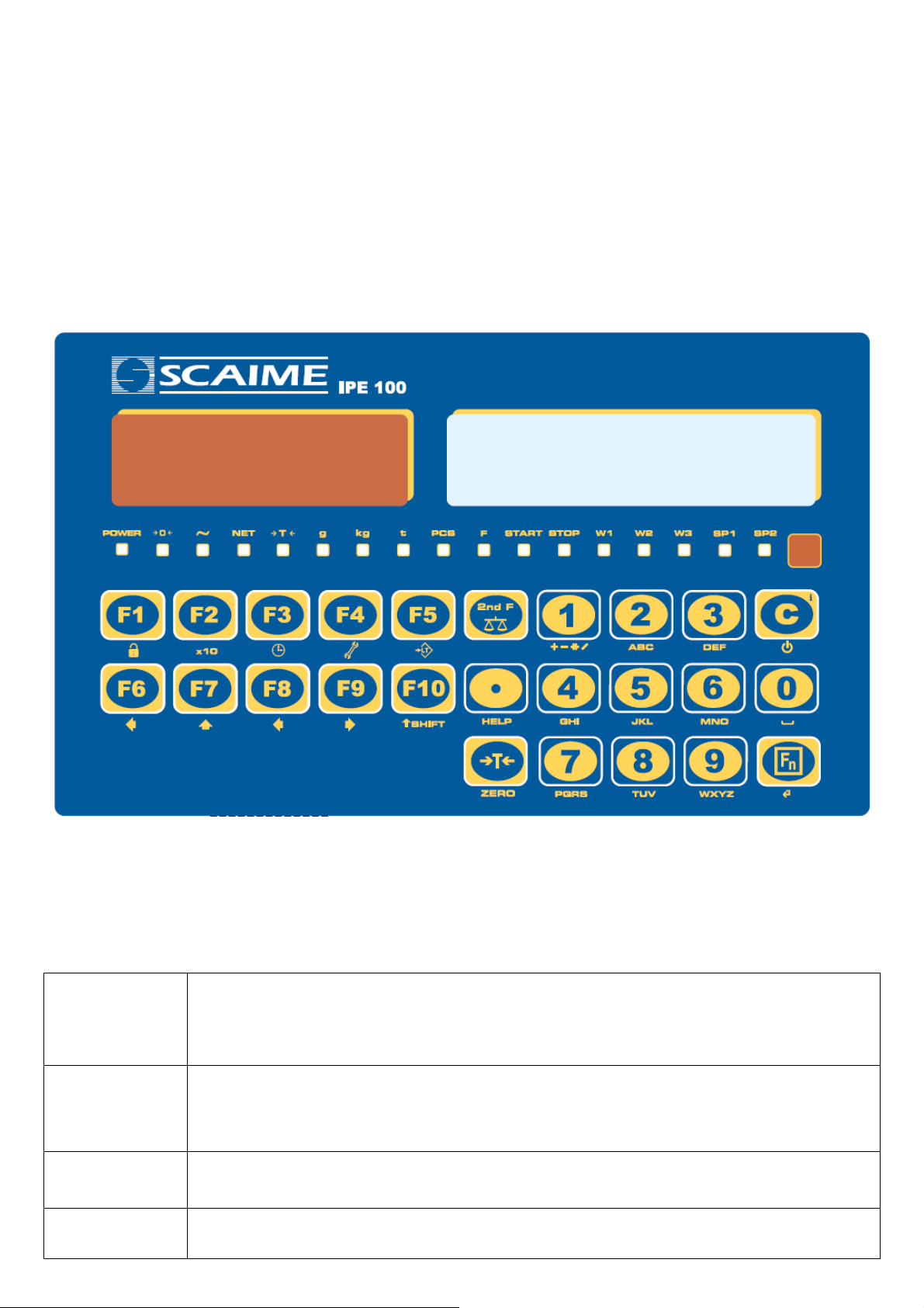
It is possible to customise the functionality of the keys through the << F.KEYS >> step.
C/DEL
TARE/ZERO
Fn/ENTER
2nd F
- Turns the instrument on/off.
- If pressed for an instant, it clears the tare value.
- Exits the parameter without confirming and saving the modifications.
- In the numeric input phase, it quickly clears the present value.
- If pressed for an instant it carries out the semiautomatic tare, or cancels the value of tare if the
gross weight is 0.
- If pressed at length, it clears the displayed gross weight, if it’s within the percentage configured in
the << 0.PErC >> step.
- In the alphanumeric input phase, it confirms the entry made.
- In the menu it allows to enter a step or to confirm a parameter inside a step.
- If pressed together with the other keys, it allows carrying out a specific function. (see section
4.1.1).
10
Page 11

IPE100 indicator NU-IPE100-IO-USER-E-0212
- In the numeric or alphanumeric input phase, it enters, in this order, the following characters:
. , ; : # < > \ | ” % & / ( ) = ? ^ ’ [ ] { };
./HELP
F1
F2
F3
F4
F5
F6
F7
F8
- HELP function, see section 4.1.4.
- If pressed in some steps or functions of the weight indicator, the display shows the keys and
their functions specific to that state of the instrument.
- By entering a number through the numerical keyboard and then pressing the F1 key, one can
quickly select the customer corresponding to the entered value (the article must have already
been edited).
- If pressed for an instant it allows entering the customer database.
- If pressed at length one locks and unlocks the instrument’s keyboard (except the C key)
- By entering a number through numerical keyboard and then pressing the F2 key, one can quickly
select the material corresponding to the entered value (the article must have already been
edited).
- If pressed for an instant it allows entering the material database.
- If pressed at length the weight visualization function with sensitivity x 10 is enabled.
- By entering a number through numerical keyboard and then pressing the F3 key, one can quickly
select the vehicle corresponding to the entered value (the article must have already been edited).
- If pressed for an instant it allows entering the vehicle database.
- If pressed at length one can adjust the date and time of the instrument.
- If pressed for an instant it allows filling in the free texts, if configured.
- If pressed at length one enters the instrument’s diagnostics menu.
- Commands the data transmission to the printer serial port.
- If pressed at length one locks/unlocks the tare.
- If pressed for an instant it allows carrying out an input weigh.
- Allow to scroll forwards in the menu steps or in the parameters inside a step.
- In the numeric or alphanumeric input phase, it decrements the blinking digit.
- If pressed for an instant it allows carrying out an output weigh.
- Allow to scroll backwards in the menu steps or in the parameters inside a step.
- In the numeric or alphanumeric input phase, it increments the blinking digit.
- If pressed for an instant it allows printing and resetting the partial total.
- In the numeric or alphanumeric input phase, it selects the digit to be modified from right to left.
F9
F10
NUMERIC
KEYBOARD
4.1.1 "2ndF" KEY: SECOND FUNCTION OF THE KEYS
In the weighing phase, by pressing the 2ndF key together with another key, it’s possible to execute various functions
(continue reading the manual for the details of the functions):
2ndF F1 Print/Clearing of Customer Total
2ndF F2 Print/Clearing of Material Total
2ndF F3 Print/Clearing of Vehicle Total
2ndF F4 Deselect databases
2ndF F5 Repetition of the last printout made
- If pressed for an instant it allows printing and resetting the general total.
- In the numeric or alphanumeric input phase, it selects the digit to be modified from left to right.
- If pressed for an instant, it executes the printing and the zeroing of the large total.
- In the numeric or alphanumeric input phase, introduces a space between two characters.
- Entry of digits or characters.
- During the weighing, these enter a numeric value with which it’s possible to:
1) Set the tare value, by pressing then the TARE key (see section 7.2).
2) To add or to subtract to the current tare the result of the operation between two values
enterable with the keyboard (See the 15.1 CALCULATOR section).
11
Page 12

IPE100 indicator NU-IPE100-IO-USER-E-0212
2ndF F8 Net/Gross Conversion 1
2ndF C Causes the display of the present metric scale information (see section 8).
2ndF TARE/ZERO Cyclical scale zero on the connected scales
2ndF 0 Selection of remote scale
2ndF 1 Selection of scale 1
2ndF 2 Selection of scale 2
2ndF 3 Selection A+B function
4.1.2 ENTERING ALPHANUMERIC TEXT
It might be necessary, while the weighing system is working, to enter some alphanumerical texts such as descriptions,
alphanumerical messages (operator, number of lot, customer, etc.).
To enter the characters one uses the 0 to 9 keys.
By pressing one of these keys a few times, the characters shown on the key (and other special carachters) will be shown
on the LCD display: initially the first letter in the bottom left will appear, and then the other characters towards the right.
After digiting a character, the blinking cursor, after a few instants, advances automatically of a position.
Function of the keys
F5 switches the writing mode from “numeric” (nuM) to “characters” (ChAr).
In the nuM mode one enters just the numbers, while in the ChAr mode one can enter all the characters of
a key.
C If pressed for an instant, it cancels the written characters: first the characters that follow the cursor are
cancelled; than those that precede it, one at a time.
If pressed at length, it deletes all entered characters.
With empty text, it exits the entry phase without confirming.
SHIFT It enters a space in the middle of a text.
./HELP If pressed a few times it allows entering the following characters: . , ; : # < > \ | ” % & / ( ) = ? ^ ’ [ ] { }.
0 In “characters” mode (ChAr), by pressing once a space is entered; by pressing twice it enters the “0”
character.
1 In “characters” mode (ChAr), pressed repeatedly, it allows to enter the following symbols:
? ! 1 @ ’ + – * / = ~ € „ … † ‡ ˆ ‰ š < OE ž ı ’ “ ” • – – ˜ ™ Š > oe ž ¢ £ ¤ ¥ ¦ § ¨ © ª « ¬ - ® ¯ ° ± ² ³ ´ μ ¶ · ¸
¹ º » ¼ ½ ¾ ¿ ã.
Moves the blinking cursor to the left or to the right.
Scrolls in one sense or the other the list of all the enterable characters (0, 1…9, A, B…Y, Z)
Examples:
- To enter the letter “B” one should press the “2” key twice in the ChAr mode.
- To enter the number “3” one should press the “3” key four times (in the ChAr mode) or press the F5 key (one passes to
the nuM mode) and press the “3” key once.
4.1.3 DISABLING THE KEYBOARD
It is possible to disable all the keyboard functions (except the C key for turning on and off), in order to avoid undesired
pressings of the scale keys:
- To lock the keyboard, press at length the F1 key: the display shows the “LoCK” message for a few instants. Now the
keyboard is LOCKED: if one presses a key, the display shows for a few instants the “HOLD F1 TO UNLOCK” message.
- To unlock the keyboard, press again at length, the F1 key: the display shows the “unLoCk” message for a few
instants.
NOTE: It’s possible to lock all keys individually in a permanent way through the TECHNICAL SETUP, TECHNICAL
MANUAL.
1
In case of APPROVED instrument and active tare, the gross weight will show for about 5 seconds, then return to the net weight visualization.
12
Page 13
IPE100 indicator NU-IPE100-IO-USER-E-0212
4.1.4 HELP MENU
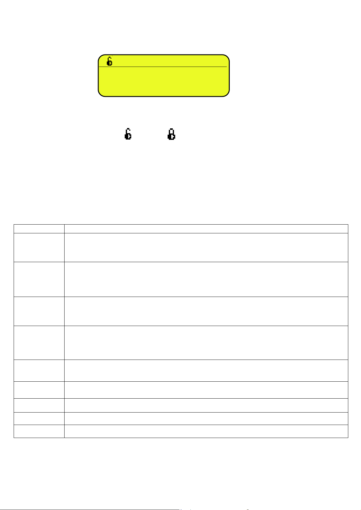
By pressing at length the HELP key it is possible to access a menu containing the list of keys with the relative function, and
status (locked or unlocked) indication.
The display shows:
- in the upper part: the key, followed by the code of the linked function in the << F.Keys >> step, and a symbol
Indicating whether the key is unlocked ( ) or locked ( ) in the << EN.KEYS >> step.
- in the lower part: the description of the linked function.
Scroll the list with the arrow keys , press the C key to exit.
F1:302 C
CUSTOMER DATABASES
4.1.5 INDICATOR CONNECTED TO PC KEYBOARD
It’s possible to connect a PC keyboard (optional), used to emulate the functions of the keys of the indicator.
The keys are managed in the following way:
KEYBOARD KEY OR FUNCTION EMULATE
Esc
and Canc
Enter
Numeric and
alphanumeric
keys, SHIFT and
CAPS LOCK
Cursor keys
Cursor keys
F1, F2….F10
-C key.
- If pressed at start-up, it allows entering in the technical SETUP.
In the alphanumeric input, it deletes all entered characters.
-C key.
- If pressed at start-up, it allows entering in the technical SETUP.
In the alphanumeric input, it cancels first the characters which follow the cursor, then the ones which
precede it, one at a time.
- Fn key.
- Confirms the entered value.
- Enters the displayed step
- Quick entry of a numeric and alphanumeric string: through the CAPS/LOCK or SHIFT key it is possible
to switch from the capital letters to the lower case letters, and vice versa, or enter the second character
corresponding to the key (for example ", %, &, /, ? )
- Scroll the parameters
- Increase or decrease the blinking digit while entering a value.
- When entering a value or an alphanumeric string, it scrolls the digits to the right or to the left.
F1,F2….F10 keys.
F11
F12
NOTE: through the remote keyboard, it’s not possible to carry out the functions made by pressing the keys at length.
2ndF key
TARE key.
13
Page 14
IPE100 indicator NU-IPE100-IO-USER-E-0212
4.1.6 REMOTE CONTROL
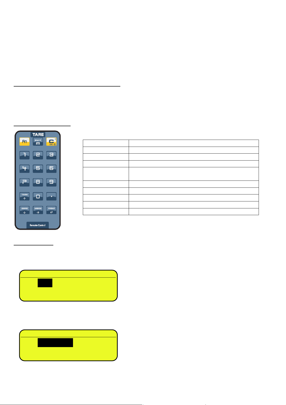
Depending on the model of indicator, it is possible to remotely control the instrument through one of the following types of
remote controls: 18-key infrared (ir) or 6-key radio (rd).
The type of remote control to be used must be selected in the Setup environment, in the << inF.Red >> step (TECHNICAL
MANUAL).
NOTE: The infrared remote controls are for indoor use only.
4.1.6.1 “18-KEY” INFRARED REMOTE CONTROL
With this type of remote control, the functioning of the keys will be as described in the following table.
The remote control can be programmed so that it will emulate the Tare key instead of the 2nd F key of the indicator and the
function keys from F1 to F10 instead of the numeric keys (numeric key 1 for F1, numeric key 2 for key F2 etc…); see below
the configuration details.
FUNCTION OF THE KEYS
CONFIGURATION
To execute this configuration:
- press at length the Fn key on the remote control;
- the configuration of the 2nd F key is proposed:
ir.2nd F
- select the desired key that should be simulated by using the arrow keys and press the PRINT / key to confirm
and pass to the following setting;
- the configuration of the numeric key is proposed:
- select the desired functioning of the numeric key (simulating the numbers or simulating the function keys from F1…F10)
by using the arrow keysand press the PRINT / key to confirm and exit the menu.
● 2nd F
○ Tare
ir.numb
● numeric keys
○ function keys
KEYBOARD KEY OR FUNCTION EMULATED
Fn Fn key
2nd F 2nd F key or Tare function (see configuration below)
C C key
NUMERIC KEYS
TARE / Tare function or increase of a digit while entering a value
. ./HELP key
ZERO / Zero function or decrease of a digit while entering a value
MODE / Scrolls the digits to the right while entering a value
PRINT /
Entry of digits or emulation of F1...F10 keys (see
configuration below)
Confirms the entered value or enters the displayed step
14
Page 15
IPE100 indicator NU-IPE100-IO-USER-E-0212
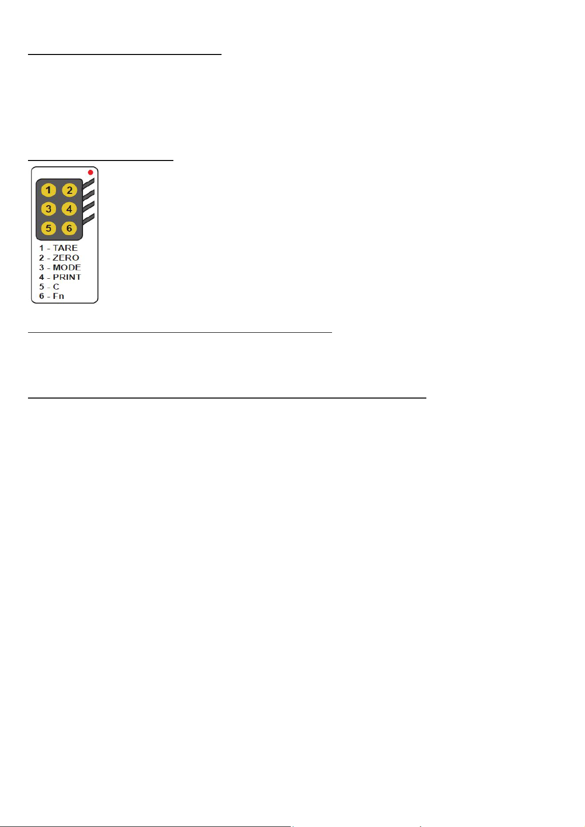
4.1.6.2 “6-KEY” RADIO REMOTE CONTROL
With this type of remote control, the functioning of each key can be programmed so that it is matched to one of the available
keys of the indicator.
This configuration must be carried out in the Setup environment, in the << inF.Red >> step (TECHNICAL MANUAL), after
the selection of this type of remote control.
By pressing the ./HELP key of the indicator, it’s possible to see, while weighing, the list of the functions matched to the keys
of the indicator and also to the keys of the remote control (see section 4.1.4).
EXAMPLE OF CONFIGURATION
USE OF MORE REMOTE CONTROLS WITH ONLY ONE INDICATOR
If one works with only an indicator, it is possible to use any 6-key remote control, without combining it to the indicator,
therefore without limiting the number of usable remote controls.
To enable this mode one has to first select “RD 6 BR” in the << inF.Red >> (TECHNICAL MANUAL).
USE OF MORE REMOTE CONTROLS WITH SEVERAL INDICATORS IN THE SAME AREA
If one needs to use several indicators in the same area, it is possible to combine each remote control to the desired
indicator, in order to execute the function only on it and therefore avoid emulating the function on all indicators in use.
By enabling this mode it will be possible to combine up to 3 different remote controls (e.i. for 3 different operators) for each
indicator.
To enable this mode one has to first select “RD 6” in the << inF.Red >> (TECHNICAL MANUAL).
To link a new remote control to the indicator one has to:
- press at length 1 and 2 keys together (3 seconds).
- the instrument displays "aut.rd?"
- press the ENTER key of the indicator
- the new remote control is linked
To remove the linking of a remote control one has to:
- press at length 1 and 2 keys together (3 seconds).
- the instrument displays "aut.rd?"
- press the C key of the indicator; if the remote control was previously linked, it will be removed.
15
Page 16
IPE100 indicator NU-IPE100-IO-USER-E-0212
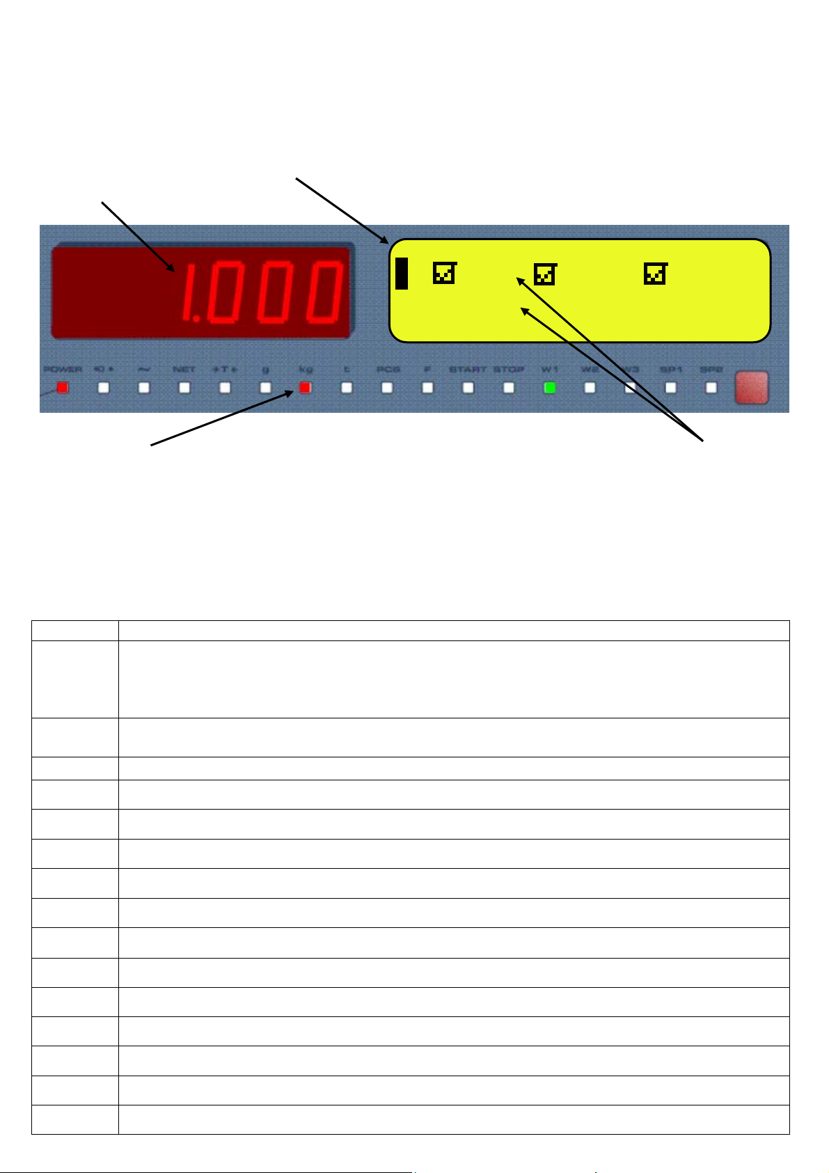
4.2 FUNCTION DISPLAY
During the weighing the displays are subdivided mainly in 3 sections, shown in the figures below:
1) WEIGHT
2) STATUS INDICATORS (led pilot lights and / or graphic symbols)
3) DATA
2
1
1 CUS MAT VEH
TARE: 1.000kg
2 3
Figure 1: IPE100 displays
NOTE: If the EEEEE message appears, this means that the value exceeds the maximum number of digits shown by the
instrument.
4.2.1 STATUS INDICATORS
LED FUNCTION
Indicates the type of indicator power supply:
POWER
0
~
- red pilot light: through built-in power adapter;
- green pilot light: through battery (charged battery);
- pilot light off: through battery (discharged battery).
Indicates that the weight detected by the weighing system is near zero, including the interval of 1/4 +1/4 of
the scale’s division.
I Indicates that the weight is unstable.
NET Indicates that the weight shown by the LED display is a NET WEIGHT.
T Indicates that a tare value has been acquired or entered.
G Indicates that the unit of measure in use is the gram.
Kg Indicates that the unit of measure in use is the kilogram.
T Indicates that the unit of measure in use is the ton.
PCS Not used in this application
F Not used in this application
START Not used in this application
STOP Not used in this application
W1 W2 W3 Measuring range (see section 8)
SP1 Not used in this application
SP2 Not used in this application
16
Page 17
IPE100 indicator NU-IPE100-IO-USER-E-0212
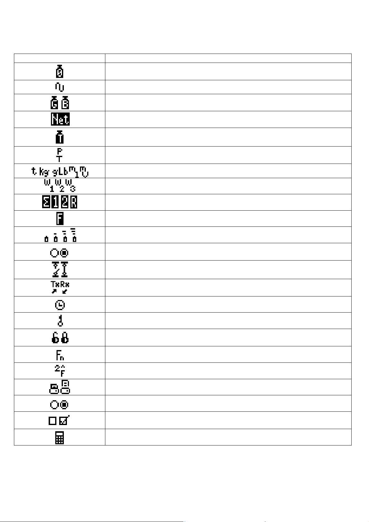
SYMBOLS SHOWN ON THE LCD DISPLAY
SYMBOL FUNCTION
The weight detected by the weighing system is near the zero, included within the interval
of –1/4 and +1/4 of the scale division.
The weight is unstable.
The displayed weight is a GROSS WEIGHT (depending on the software language).
The displayed weight is a NET WEIGHT.
A tare value has been acquired.
A manual tare value has been entered (preset tare).
Unit of measure in use: ton, kilogram, gram, pounds, millilitres, or millivolt.
Active measuring range (see section 8).
Active scale (see section 5).
Indicates that a specific function of the instrument is active.
Battery charge level: see section 5.2.1.
Status output, respectively non active and active. Icon viewable only with active
DIAGNOSTICS PERIPHERAL UNITS function, see section 15.5.
Status input, respectively non active and active. Icon viewable only with active
DIAGNOSTICS PERIPHERAL UNITS function, see section 15.5.
Serial communication status with external device. Icon viewable only with active
DIAGNOSTICS PERIPHERAL UNITS function, see section 15.5.
Active during the configuration of the date and time.
Locked keyboard, see section 4.3
In the HELP menu these respectively indicate whether a key is unlocked or locked in the
SETUP level (<< En.KEYS >> step, see section 4.4.)
The Fn key has been pressed.
The 2nd F key has been pressed.
Transmission of the data to the printer serial port under way.
Inside the step, these respectively indicate an unselected or selected parameter.
They indicate respectively if an element of archive is unselected or selected (see section
4.2.5).
Active calculator function, see section 15.1 CALCULATOR.
17
Page 18
IPE100 indicator NU-IPE100-IO-USER-E-0212
g
g
g
g
g
g
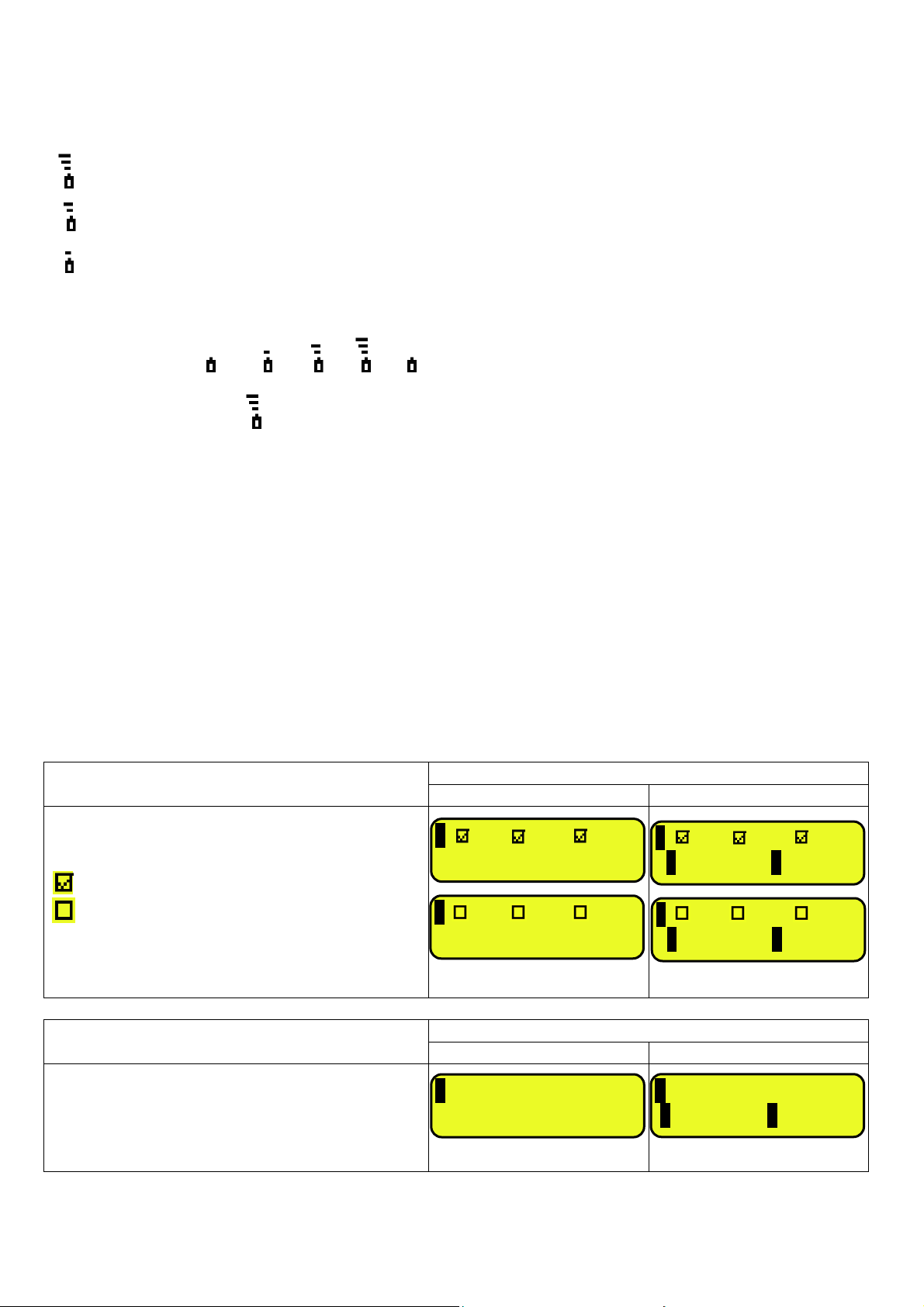
4.2.2 BATTERY LEVEL INDICATION
The indicator is able to recognise whether it is powered by mains or by battery, and to indicate its charge level; to enable
the battery level indication, one should configure the << bt.LEVEL >> step.
The charge level is shown during weighing by the battery symbol.
- : charged battery.
- : partially charged battery.
- : discharged battery: connect the indicator to the mains for recharging the battery (if provided by that model) or
replacing the battery.
The indicator shows also when the battery is being recharged (if provided for the model):
RECHARGE PHASE: …
COMPLETED RECHARGE:
NOTES:
- During the recharge the instrument can be normally used.
- The instrument automatically turns off when the voltage goes below the minimum level.
4.2.3 "TILT" DEVICE
The TILT is a device which inhibits the indicator’s weighing system and starts working when the instrument’s inclination is
greater than 2% for the pallet truck application or 5% for application on lift trucks.
The “tilt” message is shown on the display, alternate to the weight value.
The activation of the tilt alarm has a delay of about three seconds from the detection of the exceeding inclination.
See the electrical connection scheme (TECHNICAL MANUAL.) for the connection of the device.
4.2.4 DISPLAYED DATA
The data is displayed on two lines:
VISUALISATION WITH ENABLED DATABASES EXAMPLES
A+B FUNCTION DISABLED A+B FUNCTION ENABLED
- Indication of the selected elements
(CUS:customer/MAT:material/VEH:vehicle):
Element selected
Element not selected
- Active semiautomatic tare (PT if manual tare) or
weight on the scale 1 and 2
1 CUS MAT VEH
TARE: 100k
1 CUS MAT VEH
PT: 100k
1 CUS MAT VEH
1 100.0kg 2 0.0k
1 CUS MAT VEH
1 100.0kg 2 0.0k
VISUALISATION WITH DISABLED DATABASES EXAMPLES
A+B FUNCTION DISABLED A+B FUNCTION ENABLED
- Gross weight or weight sum (A+B)
- Active semiautomatic tare (PT if manual tare) or
weight on the scale 1 and 2
1 GROSS: 100kg
TARE: 100k
18
Σ SUM: 100.0kg
1 100.0kg 2 0.0k
Page 19
IPE100 indicator NU-IPE100-IO-USER-E-0212
scale 1;
scale 2;
ote scale
5. SELECTION OF THE SCALE
With various scales connected, press the 2ndF key followed by a key from 0 to 3:
0 >> Selection of remote scale.
1 >> Selection of scale number 1.
2 >> Selection of scale number 2.
3 >> scale sum selection (A+B function).
For example with the 2ndF and the 1 keys, the words “SCALE 1” appear on the display for a few seconds followed by the
value of the Weight if it is on the weighing machine selected.
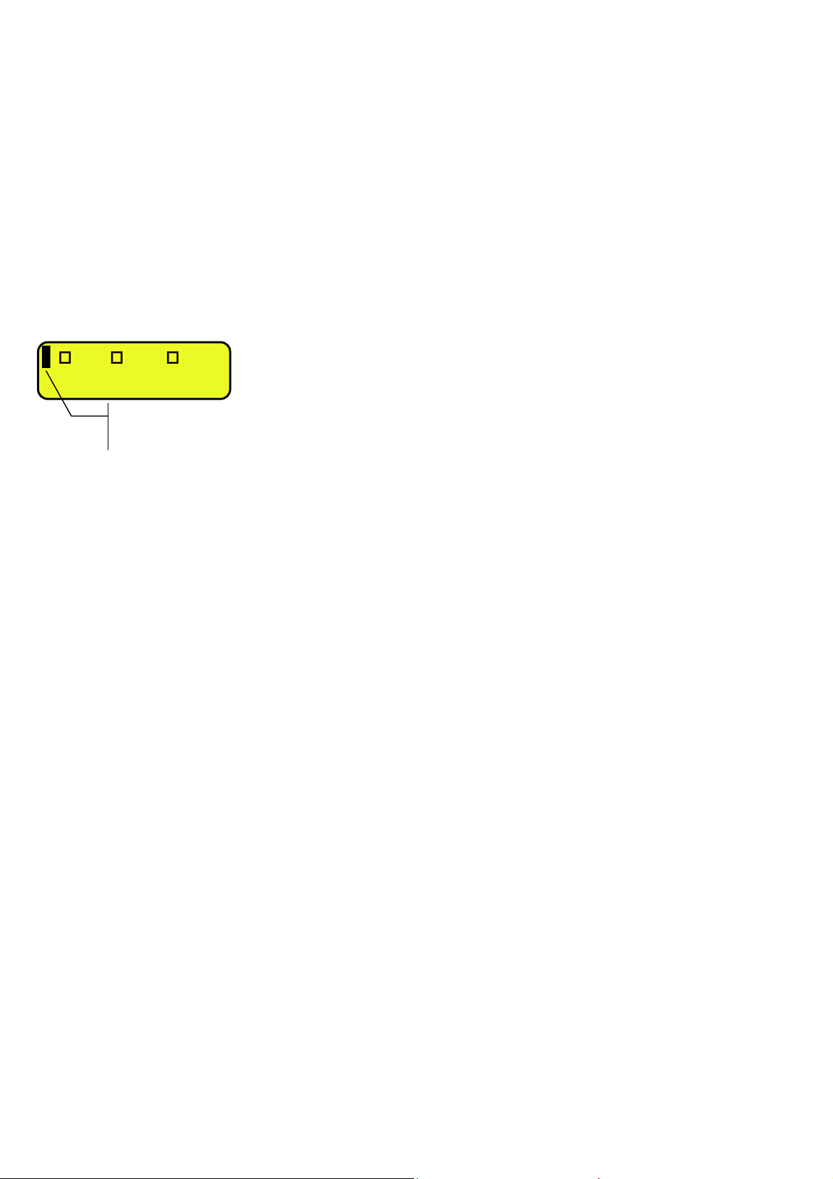
In case of various connected scales, the selected scale is shown on the LCD display of the instrument:
1 CUS MAT VEH
Selected scale:
1 =
2 =
R = rem
Σ= A+B function
19
Page 20
IPE100 indicator NU-IPE100-IO-USER-E-0212
5.1 FUNCTIONING WITH REMOTE SCALE
PREMISE: the functioning of the remote scale is foreseen with the use of independent channels (nuM.SCA step,
TECHNICAL MANUAL.).
The remote scale transmits in a continuous mode the weight string on a dedicated serial port (optional), in a unidirectional
(from scale to indicator).
It is possible to use the serial ports on the indicator’s motherboard simultaneously with the use of the remote scale.
In the normal scale status, press the 2ndF and 0 keys to pass to the display of the weight on the remote scale.
If just the remote scale is connected, after the start-up phase, the indicator positions itself directly on it.
If the remote scale allows this, it is possible to carry out the ZERO and TARE operations directly from the indicator.
It is possible to carry out all the weighing procedures described in section 13 (also using the databases), or print the
displayed weight.
For the connection refer to the technical manual of the instrument (TECHNICAL MANUAL.).
CONFIGURATION OF THE REMOTE SCALE
See the manual of the remote scale.
CONFIGURATION OF THE INDICATOR
Refer to the technical manual for programming the indicator (SEtuP >> SEriAL >> CoMAuX >> rEM.SCA step
TECHNICAL MANUAL.).
5.2 “A+B” FUNCTION
“A+B” function allows you to perform weighing operations on each scale or on their sum; the function have to be enable in
step F.ModE >> totAL >> WEi.Mod >> nor.WGt (TECHNICAL MANUAL.).
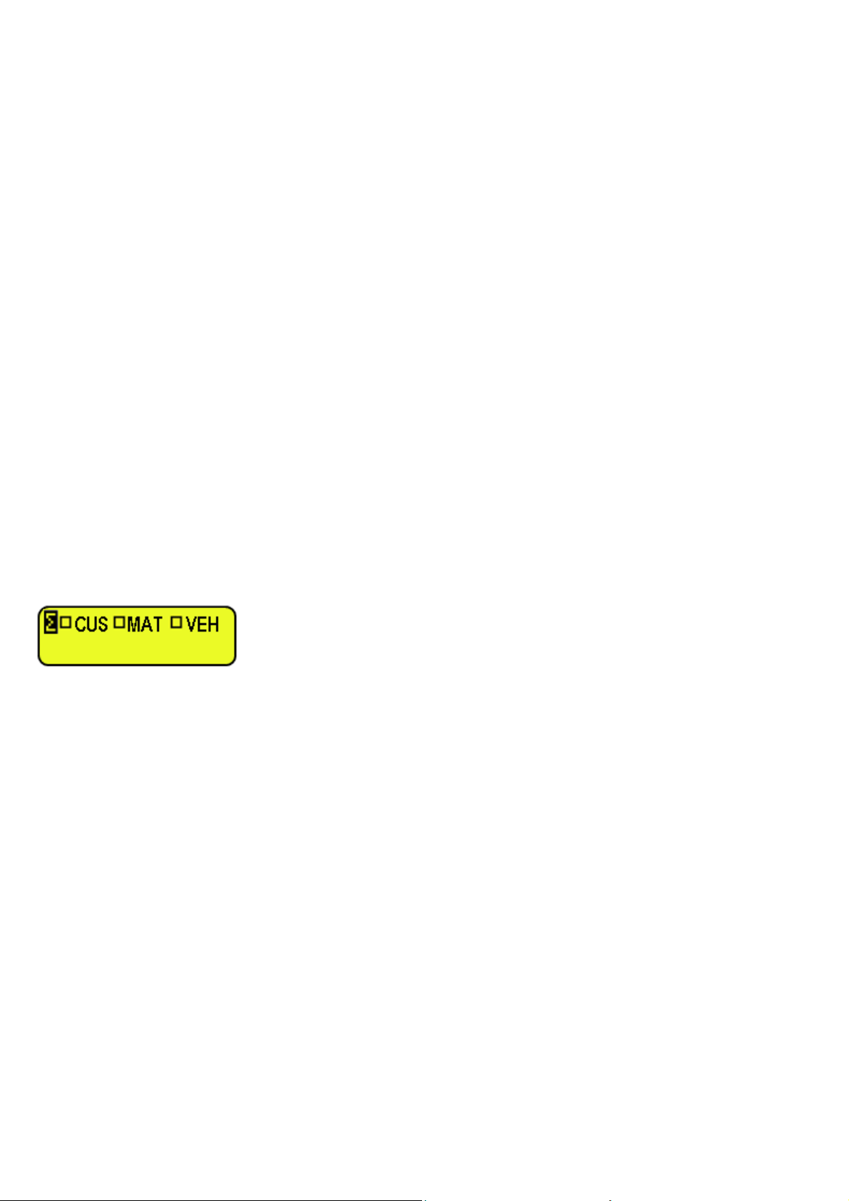
To display the sum of two scales, press in sequence the 2ndF and 3 keys, the LCD display shows:
where “Σ” indicates the sum of two scales.
NOTES
• One can select in every time scale 1 or scale 2 by pressing in sequence 2ndF and 1 or 2ndF and 2 keys.
• The total capacity corresponds to the sum of each scale capacity.
• The total division corresponds to the highest division of each scale.
• The overload signalling always corresponds to individual scale overload detection (individual scale capacity + 9e).
• The function is available for “single vehicle” functioning mode
.
• The maximum entering value of manual tare is always equal to each scale capacity.
• The manual tare is the same for all the scales: the value is shown on LCD display, while display always shows the
gross weigh.
• The semi-automatic tare is disabled (on each scale too).
• The 316 function switch the visualization between Preset Tare and the weight values.
• At start-up the indicator places itself on A+B status.
5.3 WEIGHING WITH TWO SCALES: SELECTING INPUT/OUTPUT SCALES
Since it is possible to connect a second scale, in the F.ModE >> totAL >> i.o.SCA SET INPUT/OUTPUT SCALES”
parameter of the TECHNICAL SETUP (TECHNICAL MANUAL.), one sets how to use the two scales:
• By selecting “SEt.i.o1” one sets the first scale as INPUT, and the second one as OUTPUT.
• By selecting “SEt.i.o2” one sets the first scale as INPUT as well as OUTPUT.
• By selecting “FrEE” one can freely use the two scales as: INPUT in the first / OUTPUT in the second, and vice
versa, or INPUT/OUTPUT in the first or INPUT/OUTPUT in the second.
20
Page 21

IPE100 indicator NU-IPE100-IO-USER-E-0212
6. SCALE ZERO FUNCTION
With various connected scales, select the scale using the numerical keyboard, using the 2ndF and the 0, 1, 2 and 3 keys.
Keep the ZERO key pressed; the message "Zero" appears on the display after which:
- If the weight on the scale is included in the percentage of capacity configured in the << 0.PErC >> (RIF.MAN.T.) step, it
is zeroed;
- If the weight is not within this range, it will not be cleared and an error sound is emitted.
In the end the indicator automatically returns to the display of the weight present on the scale.
6.1 CYCLICAL AUTOMATIC ZERO
If the cyclical automatic zero has been set at the start-up (in the SEtuP >> ConFig >> ParaM >> Auto 0 step of the setup,
TECHNICAL MANUAL.), by pressing the combination of the 2ndF and ZERO keys, a zero cycle is executed in all the
current scales.
7. TARE FUNCTIONS
7.1 SEMIAUTOMATIC TARE
By pressing the TARE key one tares any weight which is on the scale; the display shows “tArE” for an instant and then 0
(net weight); the NET and T, or , indicators turn on; the LCD display shows furthermore the stored tare value.
Whatever the case, a new operation automatically cancels and substitutes the previous one.
NOTES:
- The automatic tare is acquired only if the weight is of AT LEAST ONE DIVISION AND IS STABLE (~ instability led
indicator is off) and LOWER THAN THE MAXIMUM CAPACITY.
- In the “vehicle with trailer” and in the “A+B” functioning modes, the semiautomatic tare is inhibited.
7.2 PRESET TARE
To enter the tare value, one can do it in several ways:
1) With the numeric keyboard type the value (including the decimal point) and press TARE.
The C key quickly zeros the current value.
2) Select a vehicle in database linked to a tare different than 0.
The indicator automatically subtracts the entered value from the displayed weight, (the NET and T, or , indicators
turn on), as long as it is not greater than the instrument’s maximum capacity.
The LCD display shows furthermore the stored tare value, identified with “PT” (Preset Tare).
NOTES
- In the printout, the manual tare is identified with “PT” (Preset Tare).
- In the “vehicle with trailer” and in the “A+B” functioning modes, the display in any case shows the gross weight also in
the presence of a manual tare.
7.3 MANUAL CALCULATED TARE
With the “CALCULATOR” function it is possible to add or to subtract to the current tare the result of the operation between
two values enterable with the keyboard.
For the functioning specifications see the 15.1 CALCULATOR section.
7.4 TARE CANCELLATION
To cancel the stored tare:
- With an unloaded platform, press the TARE key.
- With loaded platform press in sequence the numeric 0 key and TARE.
21
Page 22

IPE100 indicator NU-IPE100-IO-USER-E-0212
7.5 LOCKED / UNLOCKED TARE
Normally, when a tare value has been entered (automatically, manually or from storage) by unloading the scale plate, the
display shows the tare value with a negative sign (LOCKED TARE). One can also choose that the tare value is cancelled
automatically, each time that the scale is unloaded (UNLOCKED TARE):
CONDITIONS FOR AUTOMATIC UNLOCKING:
- In case of SEMI AUTOMATIC TARE, the net weight before the scale unloading may also be 0.
- In case of MANUAL TARE, CALCULATED TARE or FROM DATABASE, the net weight before the scale unloading
must be of at least 2 stable divisions.
By pressing at length the F5 key it is possible to quickly lock/unlock the tare:
DISPLAY MEANING
LoCK LOCKED TARE
unLoCK UNLOCKED TARE
The setting of the tare may be made also in the “TARE LOCKED/UNLOCKED” SEtuP >> tArE t parameter of the
TECHNICAL SETUP, TECHNICAL MANUAL.
7.6 LIMITATION OF THE TARE FUNCTIONS
For specific requirements, it is possible to limit the tare functions with approved instrument; by setting “YES” in the SEtuP
>> d.SALE step of the SETUP environment (TECHNICAL MANUAL.):
- the SEMIAUTOMATIC TARE can not be modified with a manual or calculated tare, or one from database.
- the manual or calculated tare, or one from database must be entered or modified only with UNLOADED scale.
With approved instrument, the SEtuP >> d.SALE step is read only.
7.7 TARE EXECUTION MODE OR DISABLING OF THE TARE
It’s possible to select the tare execution mode, through the setting of the F.ModE >> totAL >> tArE step (TECHNICAL
MANUAL.):
- By setting "diSAbL" one disables all the tare operations;
- By setting "Lock" or “Unlock”, all the tare operations described in section 7.5 are enabled.
7.8 LINKING A PRESET TARE TO A VEHICLE IN THE DATABASE
It is possible to link a tare value to each article of the vehicle database; this tare value will be enabled with each vehicle
selection. Press the C key to cancel the stored tare entering.
See section 11.3 for further details.
8. MULTIPLE RANGE AND MULTI-INTERVAL FUNCTION
The multiple range functioning allows to subdivide the scale capacity in two or three ranges, each which is up to 3000
divisions, improving in this way the first range division in the dual range and the first two ranges in the triple range.
For example it is possible to approve the weighing system with:
- A single range: 6 kg capacity and 2 g division (3000 div.).
- Dual range: 6 /3 kg capacity and 2/1 g division (3000 + 3000 div.).
- Triple range: 15 / 6 / 3 kg capacity and 5/2/1 g division (3000 + 3000 + 3000 div.).
NOTE: For the approval of the weighing system in dual and triple ranges the cell must have better technical features in
comparison to the cell used for the approval in a single range.
This functioning is indicated by the turning on of the indicator which identify the range in which one is working: W1 first
range, W2 second range, W3 third range (if configured); by passing to the W2 range, the second range division is enabled;
by passing to the W3 range, the third range division is enabled, at this point the W1 first scale division is restored only by
passing the gross zero of the scale.
The multi-interval functioning is similar to MULTIPLE RANGE, but with the difference that a range division is enabled as
soon as one enters in its range interval (in other words without passing by the scale zero).
NOTE: The selection of the range number with multiple range and multi-interval functioning is made during the indicator
calibration (TECHNICAL MANUAL.).
22
Page 23

IPE100 indicator NU-IPE100-IO-USER-E-0212
9. DISPLAY OF METROLOGIC DATA (inFO)
The indicator is fitted with a function named “INFO”, thanks to which it is possible to view the configuration metric data:
- First range capacity, first range minimum weigh, first range division.
- Second range capacity, second range minimum weigh, second range division.
- Third range capacity, third range minimum weigh, third range division.
NOTES:
- The minimum weigh corresponds to 20 net weight divisions.
- The data of the second and third range appear only if actually configured.
To display the metrologic data:
- Press in sequence the 2ndF and C key
- “METROLOGIC INFORMATION” is displayed
- The display will show the number of the scale, the type of displayed data and its value.
- Press the F6 key to quickly scroll the following data
- Press the F7 key to quickly scroll the previous data backwards.
- Press the C key to quickly return to weighing.
10. FILLING IN THE INPUT TEXT
The indicator offers the possibility of using 15 CONFIGURABLE INPUT TEXTS (for example LOT, OPERATOR, SHIFT,
etc.), each made up of 16 heading characters and 32 content characters.
When entered in the TECHNICAL SETUP (see F.ModE >> tXt “Input text configuration” parameter, TECHNICAL
MANUAL.), these may be printed later on, if programmed in the printouts; or these may be used as a reminder.
To manually fill in the input texts it is possible to proceed in two ways:
1) If one knows the memory storage position (from 0 to 14) of the text to be modified, type the number, followed by
the F4 key: now enter the text and confirm with ENTER (the indicator returns to the weighing phase).
2) By pressing for an instant the F4 key, one accesses the complete list of the texts, for example:
- The LCD display shows “in. XX” in the first line, in which XX is the index of the free text (from 0 to 14) and THE
HEADING on the second line (or “Empty…” if empty).
- Use the arrow keys to select the text to be filled in and press ENTER: now one can enter the alphanumeric
text in the second line of the LCD display, (see chapter 4.1.2 ENTERING ALPHANUMERIC TEXT).
- Press ENTER to store and pass on to the following stored TEXT; by confirming the last entered text one returns
automatically to the weigh functioning; it is possible to exit also with the C key while in the text selection
modification phase.
NOTE:
• The entered texts remain in storage until these are substituted or cancelled.
• If no text has been configured, the pressing of the F4 key has no effect.
• Through specific print macros, it’s possible to automatically cancel the contents of all the texts, right after their printing
(TECHNICAL MANUAL.).
• For information on the entry of the alphanumeric texts, see section “4.1.2 ENTERING ALPHANUMERIC TEXT”.
10.1 QUICK MODIFICATION OF AN INPUT TEXT
By linking the number of a specific input text to the function 114 (preamble function in the << F.KEYS >> step, TECHNICAL
MANUAL.), it is possible to access directly to the modification of it with a direct key, for example F1 key to quickly access
the text 0, and F2 key to quickly access the text 1.
23
Page 24
IPE100 indicator NU-IPE100-IO-USER-E-0212
11. DATABASE
11.1 CUSTOMERS
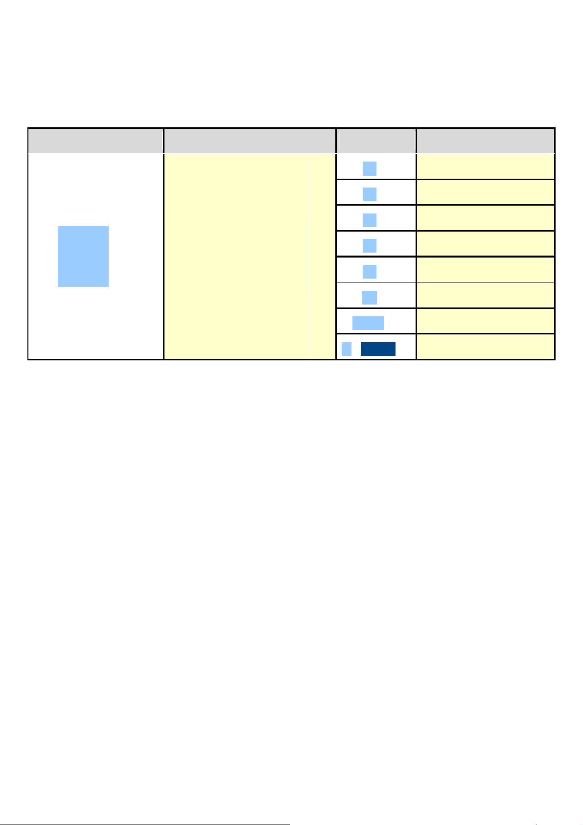
The database is made up of 500 memory storages, identified by an index from 0 to 499, each having three 25-character
descriptions; the entry / modification / cancellation of an element can be protected by a password; the unlocking
procedure is described in section 12.
KEYS ACCESS KEY MENU
F1 ► New
F2 ► Edit
F3 ► Delete
Customer Database
F4 ► Research
►
F1
Cus.dtb
►
F5 ► Print
C X
Fn ► Select
2nd F ► Deselect
. / HELP ► Help
11.1.1 ENTRY
1) Press the F1 key to access the database.
NOTE: we advise to leave empty the memory storage 0, since it is used for the temporary entry (see section “11.1.6
TEMPORARY ENTRY”).
2) Select the eventual desired position:
- By using the arrow keys
- With the keyboard by typing the storage number.
3) Press F1 to enter the customer in the desired position or in the first empty position if an already occupied position has
been selected.
4) One should fill in the following fields (only the necessary ones are requested) by pressing ENTER to confirm:
• "DESCRIPTION 1": first description line (up to 30 characters);
• "DESCRIPTION 2": second description line (up to 30 characters);
• "DESCRIPTION 3": third description line (up to 30 characters);
NOTE: the “DESCRIPTION 2” and “DESCRIPTION 3” fields request can be disabled (see F.ModE >> dtb >>
En.C.FLd step, TECHNICAL MANUAL.)
5) Restart from point 2) or press C to return to the weighing phase.
11.1.2 MODIFICATION
1) Press the F1 to access the database.
2) Select the storage to be modified:
- by using the arrow keys
- by typing the storage number with the keyboard (the LCD display shows the first corresponding DESCRIPTION
line)
- by searching the first description (see section 11.1.7)
3) Press F2.
4) Select the field to be modified by using the arrow keys and press ENTER.
5) Modify the value and press ENTER to confirm.
6) Restart from point 4) to modify other fields or press C to return to the list of storages.
7) Restart from point 2) to modify other storage or press C to return to the weighing phase.
24
Page 25

IPE100 indicator NU-IPE100-IO-USER-E-0212
11.1.3 CANCELLATION
1) Press the F1 key to access the database.
2) Select the storage to be deleted:
- by using the arrow keys
- by typing the storage number with the keyboard (the LCD display shows the first corresponding DESCRIPTION
line)
- by searching the first description (see section 11.1.7)
3) Press F3.
4) The indicator requests a further confirmation: press ENTER to confirm or another key to cancel.
5) Restart from point 2) or press C to return to the weighing phase.
11.1.4 PRINTING
1) Press the F1 to access the database.
2) Press the F5 key: the LCD display shows “PRINT?”. Confirm with ENTER or press another key to cancel. here one is
given suggestions on how to print the list of the memory storages:
- By pressing the 0 key all the memory storages in the database are printed, each with:
MEMORY N°.
DESCRIPTION1
DESCRIPTION2
DESCRIPTION3
- By pressing the 1 key, just the memories which have been handled will be printed, each with:
MEMORY N°.
DESCRIPTION1
DESCRIPTION2
DESCRIPTION3
TOTAL INPUT WEIGHT = net weight of the quantity which has entered in the factory (in other words the sum of the
net weights greater than zero [so with the input weight greater than the output weight], of all the pairs and of the
single weighs carried out).
TOTAL OUTPUT WEIGHT = net weight of the quantity which has left the factory (in other words the sum of the net
weights less than zero [so with the input weight less than the output weight], of all the pairs and of the single
weighs carried out).
NET TOTAL = the net of all transactions (TOTAL OUTPUT WEIGHT minus the TOTAL INPUT WEIGHT).
WEIGHS TOTAL = number of weigh pairs (input weigh with relative output weigh) and of all the single weighs carried
out.
3) Restart from point 2) or press C to return to the weighing phase.
11.1.5 SELECTION / DESELECTION
With no memory storage selected, the LCD display shows in the data section
(see 4.2 section ):
CUS MAT VEH
To SELECT the memory storage, one can proceed in two ways:
1) Type the memory storage number and press F1.
2) Press the F1 to access the database.
Select the memory storage:
- by using the arrow keys
- by typing the storage number with the keyboard (the LCD display shows the first corresponding DESCRIPTION
line)
- by searching the first description (see section 11.1.7)
Press ENTER.
In any case, the LCD display shows in the data section
(see 4.2 section ):
CUS MAT VEH
At this point the memory storage will be linked to the weigh under way and will be printed if foreseen in the ticket.
25
Page 26

IPE100 indicator NU-IPE100-IO-USER-E-0212
To DESELECT the memory storage, one can proceed in two ways:
1) Press the F1 key to access the database.
Press 2nd F, the LCD display shows:
DESELECT
CUSTOMER?
Press ENTER key to confirm or another key to cancel.
2) Press in sequence the 2nd F and F4 keys to deselect ALSO THE MATERIAL AND THE VEHICLE.
The LCD display shows:
DESELECT
ALL THE ITEMS?
Press ENTER to confirm or another key to cancel.
NOTE: Through specific print macros, it’s possible to deselect automatically the memory storage, right after the printing
(TECHNICAL MANUAL.).
11.1.6 ENTRY, MODIFICATION AND QUICK SELECTION OF CUSTOMER 000
It’s possible to directly enter temporary memory storage in order to avoid the filling in the database:
1) Press in sequence the 0 (NUMERIC) and F1.
2) The indicator allows directly filling in the memory storage 000; see section “11.1.1 ENTRY” for the data to be filled in.
3) Upon confirmation with ENTER of the last data, the memory storage will automatically be selected.
NOTES
- Upon each temporary entry, the 000 memory storage will be overwritten.
- By executing an output weigh, the last temporary entry made will always be printed.
11.1.7 ALPHABETICAL RESEARCH
The access to the ALPHABETICAL RESEARCH is possible in the following 2 ways:
1) by pressing the F1 to access the database and by pressing the F4 key;
or
2) through function 312 combinable with the desired key (<< F.KEYS >> step, TECHNICAL MANUAL.).
To search a customer:
1) Enter the desired characters to be searched in the first description of all the customers.
2) Select the desired storage in the list of the result by using the arrow keys and press ENTER.
3) Carry out one of the operation described in the previous sections.
11.1.8 HELP
By pressing the ./HELP key, it’s possible to see the keys list used in the menu.
The key list scrolls automatically. If you want to see the keys list, in manual mode, use the arrow key (F6 and F7 ).
26
Page 27
IPE100 indicator NU-IPE100-IO-USER-E-0212
11.2 MATERIALS
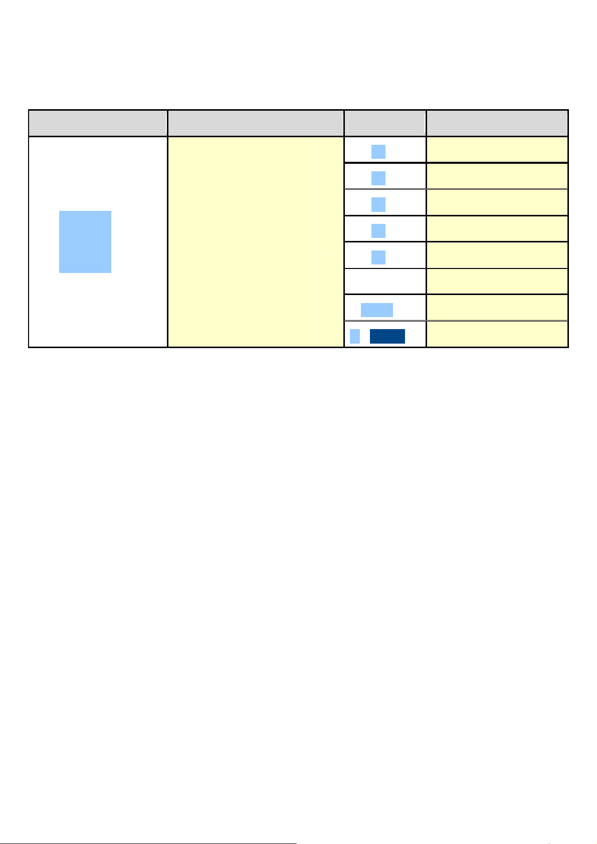
The database is made up of 500 memory storages, identified by an index from 0 to 499, each having two 20-character
descriptions; the entry / modification / cancellation of an element can be protected by a password; the unlocking
procedure is described in section 12.
KEYS ACCESS KEY MENU
F1 ► New
F2 ► Edit
F3 ► Delete
Material Database
F4 ► Research
►
F2
Mat.dtb
►
F5 ► Print
M X
Fn ► Select
2nd F ► Deselect
. / HELP ► Help
11.2.1 ENTRY
1) Press the F2 key to access the database.
NOTE: it is advisable to leave empty the 0 memory storage, since it is used for the temporary entry (see
section “11.2.6 TEMPORARY ENTRY”).
2) Select the eventual desired position
- By using the arrow keys
- with the keyboard by typing the storage number.
3) Press F1 to insert the material in the desired position, or with the first free position, if an already occupied position has
been selected.
4) One should fill in the following fields (only the necessary ones are requested); press ENTER to confirm:
• "DESCRIPTION 1": first description line (up to 20 characters);
• "DESCRIPTION 2": second description line (up to 20 characters);
NOTE: the “DESCRIPTION 2” field request can be disabled (see F.ModE >> dtb >> En.M.FLd step, RIF.MAN.T.).
5) Restart from point 2) or press C to return to the weighing phase.
11.2.2 MODIFICATION
1) Press the F2 key to access the database.
2) Select the storage to be modified:
- by using the arrow keys
- by typing the storage number with the keyboard (the LCD display shows the first corresponding DESCRIPTION
line)
- by searching the first description (see section 11.2.7)
3) Press F2.
4) Select the field to be modified by using the arrow keys and press ENTER.
5) Modify the value and press ENTER to confirm.
6) Restart from point 4) to modify other fields or press C to return to the list of storages.
7) Restart from point 2) to modify other storage or press C to return to the weighing phase.
27
Page 28

IPE100 indicator NU-IPE100-IO-USER-E-0212
11.2.3 CANCELLATION
1) Press the F2 key to access the database.
2) Select the storage to be modified:
- by using the arrow keys
- by typing the storage number with the keyboard (the LCD display shows the first corresponding DESCRIPTION
line)
- by searching the first description (see section 11.2.7)
3) Press F3.
4) The indicator requests a further confirmation: press ENTER to confirm or another key to cancel.
5) Restart from point 2) or press C to return to weighing.
11.2.4 PRINTING
1) Press the F2 key to access the database.
2) Press the F5 key: the LCD display shows “PRINT?”. Confirm with ENTER or press another key to cancel. Here one is
given suggestions on how to print the list of the memory storages:
- By pressing the 0 key all the memory storages in the database are printed, each with:
MEMORY N°.
DESCRIPTION1
DESCRIPTION2
- By pressing the 1 key, just the memories which have been handled will be printed, each with:
MEMORY N°.
DESCRIPTION1
DESCRIPTION2
TOTAL INPUT WEIGHT = net weight of the quantity which has entered in the factory (in other words the sum of the
net weights greater than zero [so with the input weight greater than the output weight], of all the pairs and of the
single weighs carried out).
TOTAL OUTPUT WEIGHT = net weight of the quantity which has left the factory (in other words the sum of the net
weights less than zero [so with the input weight less than the output weight], of all the pairs and of the single
weighs carried out).
NET TOTAL = the net of all transactions (TOTAL OUTPUT WEIGHT minus the TOTAL INPUT WEIGHT).
WEIGHS TOTAL = number of weigh pairs (input weigh with relative output weigh) and of all the single weighs
carried out.
3) Restart from point 2) or press C to return to weighing.
11.2.5 SELECTION / DESELECTION
With no memory storage selected, the LCD display shows in the data section
(see 4.2 section ):
One can SELECT the memory storage in two ways:
CUS MAT VEH
1) Type the memory storage number and press F2.
2) Press the F2 key to access the database.
Select the memory storage:
- by using the arrow keys
- by typing the storage number with the keyboard (the LCD display shows the first corresponding DESCRIPTION
line)
- by searching the first description (see section 11.2.7)
Press ENTER.
In any case, the LCD display shows in the data section (see 4.2 section ):
CUS MAT VEH
At this point the memory storage will be linked to the weigh under way and will be printed if foreseen in the ticket.
28
Page 29

IPE100 indicator NU-IPE100-IO-USER-E-0212
To DESELECT the memory storage, one may proceed in two ways:
1) Press the F2 key to access the database.
Press 2nd F, the LCD display shows:
DESELECT
MATERIAL?
Press ENTER to confirm or another key to cancel.
2) Press in sequence the 2nd F and F4 keys to deselect ALSO THE CUSTOMER AND THE VEHICLE.
The LCD display shows:
DESELECT
ALL THE ITEMS?
Press ENTER to confirm or another key to cancel.
NOTE: Through specific print macros, it’s possible to automatically deselect the memory storage, right after its printout
(TECHNICAL MANUAL.).
11.2.6 ENTRY, MODIFICATION AND QUICK SELECTION OF MATERIAL 000
It’s possible to directly enter temporary memory storage in order to avoid the filling in the database:
1) Press in sequence the 0 (NUMERIC) and F2 keys.
2) The indicator allows directly filling in the memory storage 000; seeing section “11.2.1 ENTRY” for the data to be filled
in.
3) Upon confirmation with ENTER of the last data, the memory storage will automatically be selected.
NOTES
- Upon each temporary entry, the 000 memory storage will be overwritten.
- By executing an output weigh, the last temporary entry made will always be printed.
11.2.7 ALPHABETICAL RESEARCH
The access to the ALPHABETICAL RESEARCH is possible in the following 2 ways:
1) by pressing the F2 to access the database and by pressing the F4 key;
or
2) through function 313 combinable with the desired key (<< F.KEYS >> step, TECHNICAL MANUAL.).
To search a material:
1) Enter the desired characters to be searched in the first description of all the materials.
2) Select the desired storage in the list of the result by using the arrow keys and press ENTER.
3) Carry out one of the operation described in the previous sections.
11.2.8 HELP
By pressing the ./HELP key, it’s possible to see the keys list used in the menu.
The key list is automatically. If you want to see the keys list, in manual mode, use the arrow key (F6 e F7 ).
29
Page 30
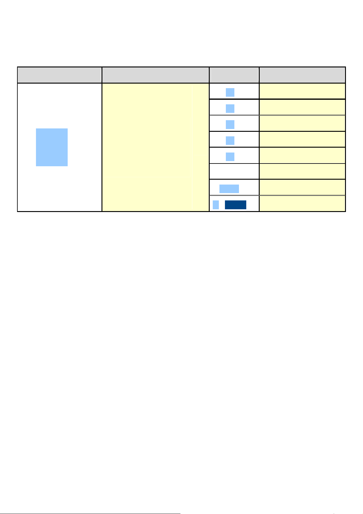
IPE100 indicator NU-IPE100-IO-USER-E-0212
11.3 VEHICLES
The database is made up of 500 memory storages, identified by an index from 0 to 499, each having a license plate of 10
characters, one 20-character description and a tare value; the entry / modification / cancellation of an element can be
protected by a password; the unlocking procedure is described in section 12.
KEYS ACCESS KEY MENU
F1 ► New
F2 ► Edit
Vehicle
Database
F3
►
Veh.dtb
►
V X
11.3.1 ENTRY
1) Press the F3 key to access the database.
NOTE: it is advisable to leave empty the 0 memory storage, since it is used for the temporary entry (see
section “11.3.6 TEMPORARY ENTRY”).
2) Select the eventual desired position using the arrow keys (or with the keyboard type the position number).
3) Press F1 to insert the vehicle in the desired position, or with the first free position, if an already occupied position has
been selected.
4) One should fill in the following fields (only the necessary ones are requested); press ENTER to confirm:
• "PLATE": plate value(up to 10 characters);
• "DESCRIPTION": description line (up to 20 characters);
• "TARE" : tare value
NOTE: the “DESCRIPTION” and “TARE” fields request can be disabled (see F.ModE >> dtb >> En.V.FLd step,
TECHNICAL MANUAL.).
5) Restart from point 2) or press C to return to weighing.
11.3.2 MODIFICATION
1) Press the F3 to access the database.
2) Select the storage to be modified:
- by using the arrow keys
- by typing the storage number with the keyboard (the LCD display shows the first corresponding PLATE line)
- by searching the plate (see section 11.3.7)
3) Press F2.
4) Select the field to be modified by using the arrow keys and press ENTER.
5) Modify the value and press ENTER to confirm.
6) Restart from point 4) to modify other fields or press C to return to the list of storages.
7) Restart from point 2) to modify other storage or press C to return to the weighing phase.
F3 ► Delete
F4 ► Research
F5 ► Print
Fn ► Select
2nd F ► Deselect
. / HELP ► Help
30
Page 31

IPE100 indicator NU-IPE100-IO-USER-E-0212
11.3.3 CANCELLATION
1) Press the F3 key to access the database.
2) Select the storage to be modified:
- by using the arrow keys
- by typing the storage number with the keyboard (the LCD display shows the first corresponding PLATE line)
- by searching the plate (see section 11.3.7)
3) Press F3.
4) The indicator requests a further confirmation: press ENTER to confirm or another key to cancel.
5) Restart from point 2) or press C to return to weighing.
11.3.4 PRINTING
1) Press the F3 key to access the database.
2) Press the F5 key: the LCD display shows “PRINT?”. Confirm with ENTER or press another key to cancel. Here one is
given suggestions on how to print the list of the memory storages:
- By pressing the 0 key all the memory storages in the database are printed, each with:
MEMORY N°.
PLATE
DESCRIPTION
TARE
- By pressing the 1 key, just the memories which have been handled will be printed, each with:
MEMORY N°.
PLATE
DESCRIPTION
TARE
TOTAL INPUT WEIGHT = net weight of the quantity which has entered in the factory (in other words the sum of the
net weights greater than zero [so with the input weight greater than the output weight], of all the pairs and of the
single weighs carried out).
TOTAL OUTPUT WEIGHT = net weight of the quantity which has left the factory (in other words the sum of the net
weights less than zero [so with the input weight less than the output weight], of all the pairs and of the single
weighs carried out).
NET TOTAL = the net of all transactions (TOTAL OUTPUT WEIGHT minus the TOTAL INPUT WEIGHT).
WEIGHS TOTAL = number of weigh pairs (input weigh with relative output weigh) and of all the single weighs
carried out.
3) Restart from point 2) or press C to return to weighing.
11.3.5 SELECTION / DESELECTION
With no memory storage selected, the LCD display shows in the data section
CUS MAT VEH
(see 4.2 section ):
To SELECT the memory storage, one can proceed in two ways:
1) Type the memory storage number and press F3.
2) Press the F3 key to access the database.
Select the memory storage:
- by using the arrow keys
- by typing the storage number with the keyboard (the LCD display shows the first corresponding PLATE line)
- by searching the plate (see section 11.3.7)
Press ENTER.
In any case, the LCD display shows in the data section
(see 4.2 section ):
CUS MAT VEH
31
Page 32

IPE100 indicator NU-IPE100-IO-USER-E-0212
At this point the memory storage will be linked to the weigh under way and will be printed if foreseen in the ticket.
To DESELECT the memory storage, one can proceed in two ways:
1) Press the F3 key to access the database.
Press 2nd F, the LCD display shows:
DESELECT
VEHICLE?
Press ENTER to confirm or another key to cancel.
2) Press in sequence the 2nd F and F4 keys to deselect ALSO THE CUSTOMER AND THE MATERIAL.
The LCD display shows:
DESELECT
ALL THE ITEMS?
Press ENTER to confirm or another key to cancel.
NOTES:
- Through specific print macros, it’s possible to automatically deselect the memory storage, right after its printout
(TECHNICAL MANUAL.).
- The deselection of the vehicle cancels also the possible linked tare.
11.3.6 ENTRY, MODIFICATION AND QUICK SELECTION OF VEHICLE 000
It’s possible to directly enter temporary memory storage in order to avoid the filling in of the database:
1) Press in sequence the 0 (NUMERIC) and F3 keys.
2) The indicator allows directly filling in the memory storage 000; seeing section 11.3.1 “ENTRY” for the data to be filled
in.
3) Upon confirmation with ENTER of the last data, the memory storage will automatically be selected.
NOTES
- Upon each temporary entry, the 000 memory storage will be overwritten.
- By executing an output weigh, the last temporary entry made will always be printed.
11.3.7 ALPHABETICAL RESEARCH
The access to the ALPHABETICAL RESEARCH is possible in the following 2 ways:
1) by pressing the F3 to access the database and by pressing the F4 key;
or
2) through function 314 combinable with the desired key (<< F.KEYS >> step, TECHNICAL MANUAL.).
To search a vehicle:
1) Enter the desired characters to be searched in the plate of all the vehicles.
2) Select the desired storage in the list of the result by using the arrow keys and press ENTER.
3) Carry out one of the operation described in the previous sections.
11.3.8 HELP
By pressing the ./HELP key, it’s possible to see the keys list used in the menu.
The key list is automatically. If you want to see the keys list, in manual mode, use the arrow key (F6 e F7 ).
32
Page 33

IPE100 indicator NU-IPE100-IO-USER-E-0212
12. DATABASE ACCESS PASSWORD
In the SETUP (F. ModE >> dtb.PWd parameter, TECHNICAL MANUAL.) one can set a password for access to the
databases. A password will be required only when one wants to insert, modify or delete an element of the file.
Afterwards, it will be no longer possible to make changes to the database without password entry.
To access the complete menu
• Press any key DURING THE VISUALISATION OF THE “uSEr”: the instrument requests the entry of the password
(a random number will appear).
• Enter the password and confirm with ENTER.
• If one does not know the password, one should give the random number to the manufacturer, who will give a
password valid ONLY FOR THAT RANDOM NUMBER.
13. WEIGHING PROCEDURES
13.1 GENERAL DESCRIPTION OF THE SYSTEM
Besides the basic standard weighing function, the IPE100 allows to keep under control the flow of goods in input and output
from a warehouse or a factory, with the possibility of simultaneously managing up to 999 vehicles, also on two scales; these
vehicles can be managed as single vehicles or as vehicles with trailer.
To guarantee correlation between the two operations, the system foresees two identification methods: through ID code or
through the LICENSE PLATE of the vehicle.
The implementation of external modules like the PC keyboard, the bar code or badge readers, allows to quicken the
weighing operations; furthermore through the “MASTER - SLAVE” function it’s possible to manage the weighing system
also from a second remote indicator.
Furthermore, the programme has been made to manage the accumulation and the printing of the weight difference.
The weight difference is automatically accumulated in the instrument totals (PARTIAL, GENERAL, GRAND TOTAL), and
the weighs’ progressives are automatically increased relative to the previously shown totals.
Furthermore, if a customer/material/vehicle has been enabled, the instrument increases both the totals as well as the
weighs’ progressive relative to the selected article.
13.2 WEIGHING THROUGH ID CODE
NOTE: the functioning mode must be enabled: set F.ModE >> totAL >> WEi.MEM step of the SETUP environment on
“WEi.Cod” (TECHNICAL MANUAL.).
In this functioning mode, the indicator links each input weigh to the lowest available ID (from 1 to 999); consequently, if an
output weigh is executed correctly, the relative ID code will be made available for the following input weigh.
It’s possible to have the ID code of the input weigh to be always consequential (therefore also if an ID lower than the last
one stored is available) by setting the F.ModE >> totAL >> Pro.LSt step in the SETUP on “DISABLE”, TECHNICAL
MANUAL.
13.2.1 INPUT WEIGH
13.2.1.1 SINGLE VEHICLE
(F.ModE >> totAL >> WEi.Mod step set on “nor.WGt”, TECHNICAL MANUAL.)
- Position the vehicle on the scale.
- Select, if requested, the customer / material / vehicle to be linked to the weigh.
- Press the F6 key, the LCD display will show:
ENTRY WEIGH
READING WEIGHT
- The indicator executes the printout (if configured), and then it displays the weight on the scale.
33
Page 34
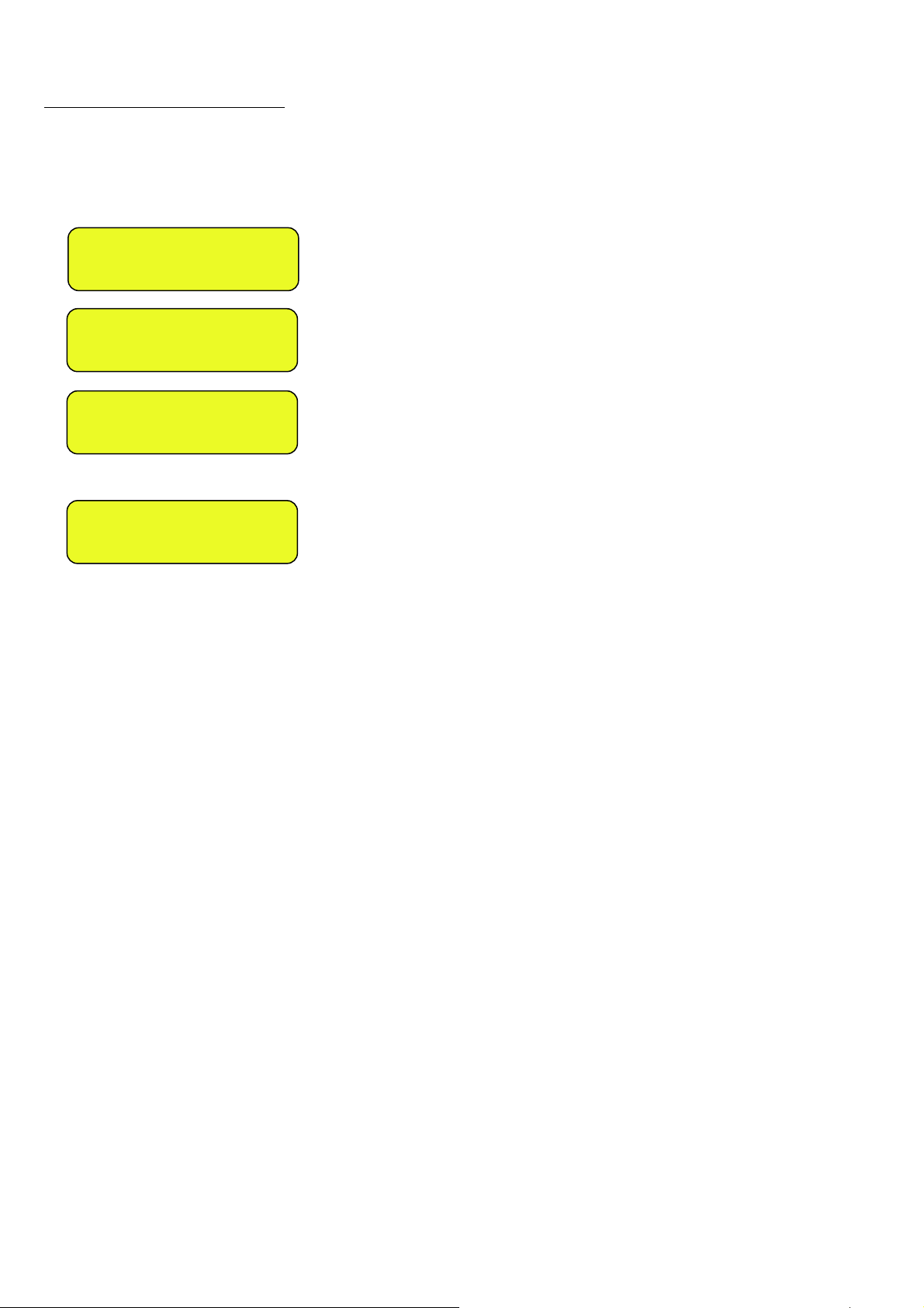
IPE100 indicator NU-IPE100-IO-USER-E-0212
13.2.1.2 VEHICLE WITH TRAILER
(F.ModE >> totAL >> WEi.Mod step set on “SEC.WGt”, TECHNICAL MANUAL.)
- Position the vehicle on the scale.
- Select, if requested, the customer / material / vehicle to be linked to the weigh.
- Press the F6 key, the LCD display will show:
ENTRY WEIGH
READING WEIGHT
SECOND WEIGH?
ENTER=YES C=NO
Or, if one has configured TWO SCALES:
SECOND WEIGH? C=NO
1=SCL.1 2=SCL.2
At this point one should position the trailer on the scale; wait a few instants for the weight stability.
By pressing ENTER it is possible to:
- CONFIRM THE SAME If the F.Mode >> totAL >> C.EntEr parameter of the setup is set on
PLATFORM “ConFEr” (CONFIRM SCALE), TECHNICAL MANUAL.
- CHANGE PLATFORM: If the F.Mode >> totAL >> C.EntEr parameter of the setup is set on
“inVErt” (INVERT SCALE), TECHNICAL MANUAL.
Note: It is in any case possible to change the platform by pressing the 1 key for platform 1 or the 2 key for platform 2.
In the printout, the trailer weight will be shown on the side (“TRAILER” item), right after the trailer weight (“INPUT” item).
By pressing C the weigh will be carried out anyways, but only the trailer weight will be taken into consideration and printed
(“INPUT” item).
NOTES ON INPUT WEIGHING
• If there is a tare, a SINGLE WEIGH is executed; therefore no ID code is occupied.
• If all the 999 memory storages are occupied without executing any output weigh, upon the execution of the following
input weigh, the indicator shows the message “WEIGHS MEMORY FINISHED”; one must execute at least one output
weigh in order to free up the memory to be used.
To cancel all the memory storages, go to the Prn.ViS >>> 0.W.List step in the menu of the ENTER key.
If one needs to execute a simple weigh without any input/output weigh and databases, we advise to use the
print key, in order to not occupy ID codes.
• If the output weigh has been made with a selected vehicle, one should execute the output weigh in order to reuse the
same vehicle in a new weigh (the LCD display shows “PLATE ALREADY PRESENT!”).
34
Page 35
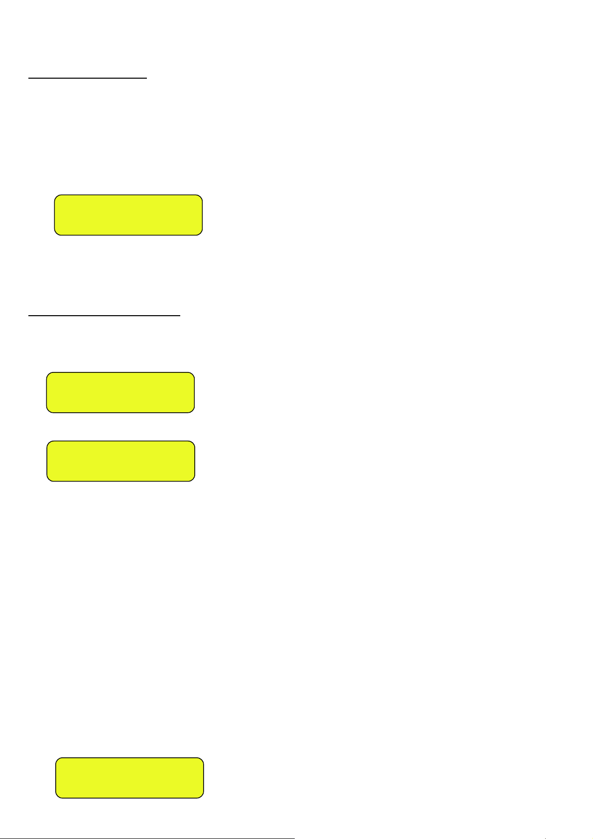
IPE100 indicator NU-IPE100-IO-USER-E-0212
13.2.2 OUTPUT WEIGH
13.2.2.1 SINGLE VEHICLE
(F.ModE >> totAL >> WEi.Mod step set on “nor.WGt”, TECHNICAL MANUAL.)
- Position the vehicle on the scale.
- Select, if requested, the customer / material / vehicle to be linked to the weigh.
- Now it’s possible to proceed in two ways:
1) Directly type in the ID code and press F7.
2) Press F7: one enters the menu of the “open” input weighs:
ID: 1
IN: 995kg
Select the desired weigh using the arrow keys .
Confirm with ENTER or press C to exit.
- In both cases, the indicator executes the printout (if configured), and then displays the weight on the scale.
13.2.2.2 VEHICLE WITH TRAILER
(F.ModE >> totAL >> WEi.Mod step set on “SEC.WGt”, TECHNICAL MANUAL.)
- Proceed the same way with the weigh of the single vehicle (see previous paragraph).
- The LCD display will show:
SECOND WEIGH?
ENTER=YES C=NO
Or, if one has configured TWO SCALES:
SECOND WEIGH? C=NO
1=SCL.1 2=SCL.2
At this point one should position the trailer on the scale, wait a few instants for the weight stability.
By pressing ENTER it is possible to:
- CONFIRM THE SAME If in the F.ModE >> totAL >> C.EntEr parameter of the setup one sets PLATFORM
“ConFEr” (CONFIRM SCALE), TECHNICAL MANUAL.
- CHANGE PLATFORM: If in the F.ModE >> totAL >> C.EntEr parameter of the setup one sets “inVErt” (INVERT
SCALE), TECHNICAL MANUAL.
Note: It is in any case possible to change the platform by pressing the 1 key for platform 1 or the 2 key for platform 2.
In the printout, the trailer weight will be shown separately (“TRAILER” item), right below the tractor weight (“OUTPUT” item).
By pressing C the weigh is cancelled and the indicator returns to the weighing mode (“OUTPUT” item).
NOTES ON THE OUTPUT WEIGH:
• If there is a tare, a SINGLE WEIGH is executed.
• By entering an ID code not yet linked to a weigh, the indicator shows on the LCD display “MEMORY IS EMPTY”
and emits a prolonged sound; then it cancels the weigh and returns to weighing.
• By entering the ID code of an already executed weigh, the LCD display will show:
W E I G H A L R E A D Y
D O N E , C O N T I N U E ?
35
Page 36

IPE100 indicator NU-IPE100-IO-USER-E-0212
Confirm with ENTER or press another key to cancel.
• If no input weigh has been made, if one then enters the menu of the “open” weighs, the indicator will show on the
LCD display “NO OPEN WEIGHS IN INPUT” and will emit a prolonged sound; then it will cancel the weigh and return
to weighing.
13.3 WEIGHING THROUGH VEHICLE LICENSE PLATE
NOTE: the functioning mode must be enabled: set F.ModE >> totAL >> WEi.MEM step of the SETUP environment on
“PLAtE” (TECHNICAL MANUAL.).
In this functioning mode, the indicator links the selected plate (through the vehicle) to the input weigh.
13.3.1 INPUT WEIGH
13.3.1.1 SINGLE VEHICLE
(F.ModE >> totAL >> WEi.Mod step of the setup set on “nor.WGt”,TECHNICAL MANUAL.)
The procedure is the same as the weighing through ID code (see section 13.2.1.1).
13.3.1.2 VEHICLE WITH TRAILER
(F.ModE >> totAL >> WEi.Mod step of the setup set on“SEC.WGt”, TECHNICAL MANUAL.)
The procedure is the same as the weighing through ID code (see section 13.2.1.2).
NOTES ON INPUT WEIGHING
• One must select a vehicle, otherwise the indicator will show on the LCD display “PLATE NOT PRESENT” and will
emit a prolonged sound; and then it cancels the weigh and returns to weighing.
• If there is a tare, a SINGLE WEIGH is executed.
• If one executes 999 weighs without executing any output weigh, when one executes the following input weigh, the
indicator will display the message “WEIGHS MEMORY EMPTY”; one should execute at least one output weigh in
order to free up the memory storage to be used.
To cancel all the memory storages, go to the Prn.ViS >>> 0.W.List step in the menu of the ENTER key.
If one needs to make a simple weigh without any input/output and databases, it is advisable to use the print
key, in order to not occupy the memory storages.
• If one executes the input weigh with a selected vehicle, one should execute the output weigh, in order to reuse the
same vehicle in a new weigh (the LCD display shows “PLATE ALREADY PRESENT!”).
13.3.2 OUTPUT WEIGHING
13.3.2.1 SINGLE VEHICLE
(F.ModE >> totAL >> WEi.Mod step of the setup set on “nor.WGt”, TECHNICAL MANUAL.)
- Position the vehicle on the scale.
- Select, if requested, the customer / material to be linked to the weigh.
- Now it’s possible to proceed in two ways:
Press F7, the LCD display will show:
INSERT
PLATE
_
36
Page 37
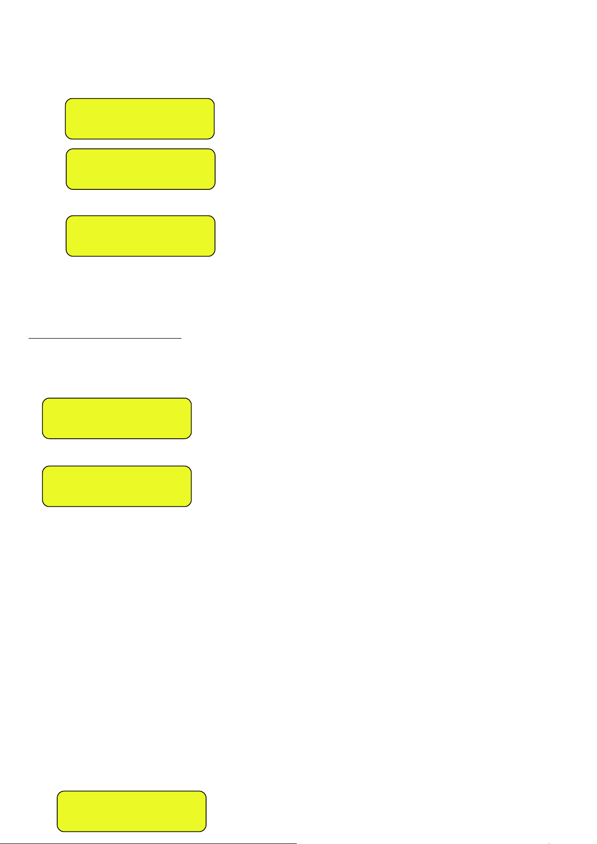
IPE100 indicator NU-IPE100-IO-USER-E-0212
Enter the license plate number and press ENTER.
1) Press F7, the LCD display will show:
INSERT
PLATE
_
Press ENTER, one enters the menu of the “open” input weighs:
CM884FK
IN: 995kg
Select the desired weigh using the arrow keys .
Confirm with ENTER or press C to exit.
- In both cases, the indicator executes the printout (if configured) and then displays the weight on the scale.
13.3.2.2 VEHICLE WITH TRAILER
(F.ModE >> totAL >> WEi.Mod step of the setup set on “SEC.WGt”, TECHNICAL MANUAL.)
- Proceed the same way as with the weigh of the single vehicle (see previous section).
- The LCD display will show:
SECOND WEIGH?
ENTER=YES C=NO
Or, if one has configured TWO SCALES:
SECOND WEIGH? C=NO
1=SCL.1 2=SCL.2
At this point one should position the trailer on the scale, wait a few instants for the weight stability.
By pressing ENTER it is possible to:
- CONFIRM THE SAME If in the F.Mode >> totAL >> C.EntEr parameter of the setup one has set
PLATFORM “ConFEr” (CONFIRM SCALE), TECHNICAL MANUAL.
- CHANGE PLATFORM If in the F.Mode >> totAL >> C.EntEr parameter of the setup one has set “inVErt”
(INVERT SCALE), TECHNICAL MANUAL.
Note: It is in any case possible to change the platform by pressing the 1 key for platform 1 or the 2 key for platform 2.
In the printout, the trailer weight will be shown separately (“TRAILER” item), right below the tractor weight (“OUTPUT” item).
By pressing C the weigh is cancelled and the indicator returns to the weighing mode (“OUTPUT” item).
NOTES ON THE OUTPUT WEIGH
• If there is a tare, a SINGLE WEIGH is executed.
• By entering an incorrect license plate or not linked to a weigh, the indicator will show on the LCD display
“PLATE NOT PRESENT” emitting a prolonged sound; then it will cancel the weigh and return to weighing.
• By entering the plate of an already executed weigh, the LCD display will show:
W E I G H A L R E A D Y
D O N E , C O N T I N U E ?
37
Page 38

IPE100 indicator NU-IPE100-IO-USER-E-0212
Confirm with ENTER or press another key to cancel.
• If no input weigh has been made, if one then enters the menu of the “open” weighs, the indicator will show on the
LCD display “NO OPEN WEIGHS IN INPUT” and will emit a prolonged sound; then it will cancel the weigh and return
to weighing.
13.4 CONDITIONS FOR TOTALISATION
With APPROVED instrument:
- the INPUT or OUTPUT weigh functions with a minimum weight of 20 divisions and reactivates according to how the
F.ModE >> rEACt. “REACTIVATIONS” parameter of the TECHNICAL SETUP has been programmed (RIF.MAN.T.), in
other words the weight movement or passage by zero of the weight; furthermore the F6 key excludes the F7 and the
printout keys and vice versa.
- the totalisation excludes the simple print function and vice versa.
With NON APPROVED instrument:
- the INPUT or OUTPUT weigh functions with a weight greater than zero and reactivates according to how the F.ModE
>> rEACt. “REACTIVATIONS” parameter of the TECHNICAL SETUP (TECHNICAL MANUAL.) has been programmed;
furthermore the F6 key excludes the F7 key and vice versa.
- the totalisation does not exclude the simple print function.
13.5 ADDITIONAL TARE FUNCTION
This function is useful if one wants to calculate the loaded/unloaded weight at the net of a tare added to the weight of the
vehicle taken into consideration.
By enabling the function in the F.ModE >> totAL >> Add.tAr step, it’s possible to have that, upon the output weigh, one is
asked to enter an additional tare, which will be subtracted from the loaded/unloaded weight value in the weigh.
After the pressing of the F7 key and the selection of the “open” weigh in input, one enters the calculator environment (the
LCD display shows the message “ADDITIONAL TARE”).
Procedure:
With the numerical keyboard enter the first value then
• Press Fn in order to consider this value as an additional tare
or
• Press F1 to add, F2 to multiply, F3 to subtract:
- With the numeric keyboard enter the second value of the operation.
- PRESS ENTER: the result will be shown for a few seconds on the display.
The printing of the “CALCULATOR” print function will not be made, but one proceeds with the printing of the output weigh.
The result of the additional tare is automatically subtracted from the loaded or unloaded weight.
13.6 TOLERANCE WEIGHING FIELD
It is possible to establish a weight interval (in between 0 and the scale capacity) for executing an input or output weigh;
outside this interval, the operation is not accepted (when the F6 or F7 key is pressed the LCD display shows the “WEIGHT
OUT OF THRESHOLD” message for a few seconds.
SETTING OF WEIGHT THRESHOLD:
• Through the 500 function, combinable with the desired key (<< F.KEYS >> step, TECHNICAL MANUAL.), it’s possible
to access the “thr.hi" menu (Maximum Threshold Setting): set the upper totalisation threshold and press ENTER.
• Through the 501 function, combinable with the desired key (<< F.KEYS >> step, TECHNICAL MANUAL.), it’s possible
to access the “thr.Lo" menu (Minimum Threshold Setting): set the lower totalisation threshold and press ENTER.
NOTES:
- By setting 0 in the maximum threshold, it’s possible to totalise up to the maximum capacity of the scale.
- By setting 0 in both thresholds, the functions are disabled.
- The totalisation field is valid for all totalisation types (input/output and single weigh).
38
Page 39

IPE100 indicator NU-IPE100-IO-USER-E-0212
13.7 REENABLING THE PRINTING AND INPUT / OUTPUT WEIGH
After having carried out an input/output weigh or a single weigh, in order to carry out a new one, the displayed weight must
pass by the zero or become unstable.
This setting is made in the SETUP environment, in the F.ModE >> rEACt. parameter (TECHNICAL MANUAL.).
While using the indicator, one may incur in the “WEIGHT NOT PASSED BY 0 OR UNSTAB.” error shown on the LCD
display, this means that the function which one wants to carry out, must be reenabled (in order to avoid accidental
executions).
In any case, one can also exclude this type of check: in order to do this, one should set “ALWAYS” in the F.ModE >> totAL
>> t.ModE step (TECHNICAL MANUAL.)
13.8 VISUALISATION AND CLEARING OF THE ACCUMULATED TOTALS
Each total can be momentarily viewed on the display or cleared independently through the printout, linking the
corresponding function to the desired key (<< F.KEYS >> step, TECHNICAL MANUAL.):
TOTAL FUNCTION CODE FOR
VISUALISATION
FUNCTION CODE FOR
RESETTING
PARTIAL TOTAL 416 418
GENERAL TOTAL 419 421
GRAND TOTAL 422 424
CUSTOMER TOTAL 404 406
MATERIAL TOTAL 408 410
VEHICLE TOTAL 412 414
ALL CUSTOMERS TOTAL - 407
ALL MATERIALS TOTAL - 411
ALL VEHICLES TOTAL - 415
ALL SCALE TOTAL
- 425
(partial total, general total, grand total)
LIST SAMPLES - 426
By recalling one of the clearing functions, the instrument requests a confirmation before proceeding with the cancellation:
press ENTER to clear, C for continuing to accumulate.
It’s possible to disable the confirmation request, in the F.ModE >> totAL >> rESEt step, TECHNICAL MANUAL.
In case of visualisation of the total, the instrument automatically exits the function after a few seconds.
NOTES:
- The weight data of the cleared total will be updated only with the subsequent input/output weigh or single weigh.
- The ARTICLE TOTAL is article specific, in other words, there is a total for EACH ARTICLE USED.
The other totals are GENERIC, and can be cleared INDEPENDENTLY ONE FROM THE OTHER (i.e. if one clears the
Grand total, with the following input/output weigh, the other totals will continue to increment, while the Grand total will
restart from 0).
- By clearing the weighs’ list one obtains the clearing of all the “open” input weighs: By carrying out this operation all the
weighing operations under way are cancelled.
13.9 PROGRESSIVES
13.9.1 PROGRESSIVE DIGITS
Through function 401, combinable with the desired key (<< F.KEYS >> step, TECHNICAL MANUAL.), it’s possible to set
the number of digits with which the TICKET PROGRESSIVE and LOT PROGRESSIVE are printed.
The number of settable digits varies from 4 to 16, organised in this way:
- if the actual digits of the total are less than the number of digits set in this step, the difference is filled with some
spaces.
- if the actual digits are greater than the number of digits set in this step, only the ones actually entered are taken into
consideration (counting from right to left).
The alignment of the total fields is on the left.
39
Page 40

IPE100 indicator NU-IPE100-IO-USER-E-0212
NOTE: The number of settable digits DOES NOT INCLUDE the comma.
13.9.2 TICKET PROGRESSIVE
Through function 402, combinable with the desired key (<< F.KEYS >> step, TECHNICAL MANUAL.), it’s possible to
modify or clear the TICKET PROGRESSIVE (up to 5 digits).
The TICKET PROGRESSIVE is a progressive number which increments of one UPON THE FIRST TOTALISATION
SUBSEQUENT TO THE CLEARING OF THE PARTIAL TOTAL.
13.9.3 LOT PROGRESSIVE
Through function 403, combinable with the desired key (<< F.KEYS >> step, TECHNICAL MANUAL.), one obtains the
clearing of the AUTOMATIC LOT (up to 6 digits); before carrying out the actual clearing, one is asked to confirm or cancel
the operation; confirm with ENTER.
The AUTOMATIC LOT is a progressive number which increments of one UPON THE FIRST TOTALISATION
SUBSEQUENT TO THE CLEARING OF THE GENERAL TOTAL..
14. PRINTOUTS
The instrument is fitted with 12 different print functions, which may be used while weighing, and of 30 print formats, in other
words, 30 different memory storages, each of which contain a programmable printout.
The printouts executed by 12 of these functions depends on the print format linked to it; see the following section for the
linkages.
The format linking function allows executing various printouts, by changing the linked format each time.
The available functions are:
SIMPLE PRINTOUT - Programmable printout -
Through the F5 key one prints the linked format, without executing the input/output weigh or single weigh.
With the APPROVED instrument:
- The printing works if there is a NET WEIGHT of at least 20 divisions.
- The printout is reenabled depending on how the F.ModE >> rEACt parameter has been programmed in the
TECHNICAL SETUP (TECHNICAL MANUAL.).
- The simple print function excludes the totalisation and vice versa.
With the NON APPROVED instrument:
- The printing works if there is a NET WEIGHT greater than zero.
- The simple printout does not exclude the totalisation and is always active (the programming of the F.ModE >> rEACt
parameter of the TECHNICAL SETUP TECHNICAL MANUAL. is not taken into consideration).
INPUT WEIGH - Programmable printout -
With the F6 key one prints the data relative to the INPUT WEIGH (format linked to the S.F.06 function), or to the SINGLE
WEIGH (format linked to the S.F.05 function) in case the known tare has been entered.
For the totalisation conditions, see section 13.4.
OUTPUT WEIGH - Programmable printout With the F7 key one prints the data relative to the OUTPUT WEIGH (format linked to the S.F.07 function) or to the SINGLE
WEIGH (format linked to the S.F.05 function) in the case that the known tare has been entered.
For the totalisation conditions, see section 13.4.
40
Page 41

IPE100 indicator NU-IPE100-IO-USER-E-0212
CUSTOMER TOTAL - Programmable printout By pressing the 2nd F key followed by F1, the CUSTOMER TOTAL is printed and then cleared as well as the printing of the
format linked to the S.F.08 function. Please find below the default printout:
DESCRIPTION1
DESCRIPTION2
DESCRIPTION3
TOTAL INPUT WEIGHT = net weight of the quantity which has entered in the factory (in other words the sum of the
net weights greater than zero [so with the input weight greater than the output weight], of all the pairs and of the single
weighs carried out).
TOTAL OUTPUT WEIGHT = net weight of the quantity which has left the factory (in other words the sum of the net
weights less than zero [so with the input weight less than the output weight], of all the pairs and of the single weighs
carried out).
NET TOTAL = the net of all transactions (TOTAL OUTPUT WEIGHT minus the TOTAL INPUT WEIGHT).
WEIGHS TOTAL = number of weigh pairs (input weigh with relative output weigh) and of all the single weighs
carried out.
MATERIAL TOTAL - Programmable printout By pressing the 2nd F key followed by F2, the MATERIAL TOTAL is printed and then cleared as well as the printing of the
format linked to the S.F.09 function. Please find below the default printout:
DESCRIPTION1
DESCRIPTION2
TOTAL INPUT WEIGHT = net weight of the quantity which has entered in the factory (in other words the sum of the
net weights greater than zero [so with the input weight greater than the output weight], of all the pairs and of the single
weighs carried out).
TOTAL OUTPUT WEIGHT = net weight of the quantity which has left the factory (in other words the sum of the net
weights less than zero [so with the input weight less than the output weight], of all the pairs and of the single weighs
carried out).
NET TOTAL = the net of all transactions (TOTAL OUTPUT WEIGHT minus the TOTAL INPUT WEIGHT).
WEIGHS TOTAL = number of weigh pairs (input weigh with relative output weigh) and of all the single weighs
carried out.
VEHICLE TOTAL - Programmable printout By pressing the 2nd F key followed by F3, the VEHICLE TOTAL is printed and cleared as well as the printing of the format
linked to the S.F.10 function. Please find below the default printout:
DESCRIPTION
PLATE
TARE
TOTAL INPUT WEIGHT = net weight of the quantity which has entered in the factory (in other words the sum of the
net weights greater than zero [so with the input weight greater than the output weight], of all the pairs and of the single
weighs carried out).
TOTAL OUTPUT WEIGHT = net weight of the quantity which has left the factory (in other words the sum of the net
weights less than zero [so with the input weight less than the output weight], of all the pairs and of the single weighs
carried out).
NET TOTAL = the net of all transactions (TOTAL OUTPUT WEIGHT minus the TOTAL INPUT WEIGHT).
WEIGHS TOTAL = number of weigh pairs (input weigh with relative output weigh) and of all the single weighs
carried out.
PARTIAL TOTAL - Programmable printout By pressing the F8 key the PARTIAL TOTAL is printed and then cleared as well as the printing of the format linked to the
S.F.02 function.
GENERAL TOTAL - Programmable printout -
By pressing the F9 key the PARTIAL TOTAL is printed and then cleared as well as the printing of the format linked to the
S.F.03 function.
41
Page 42
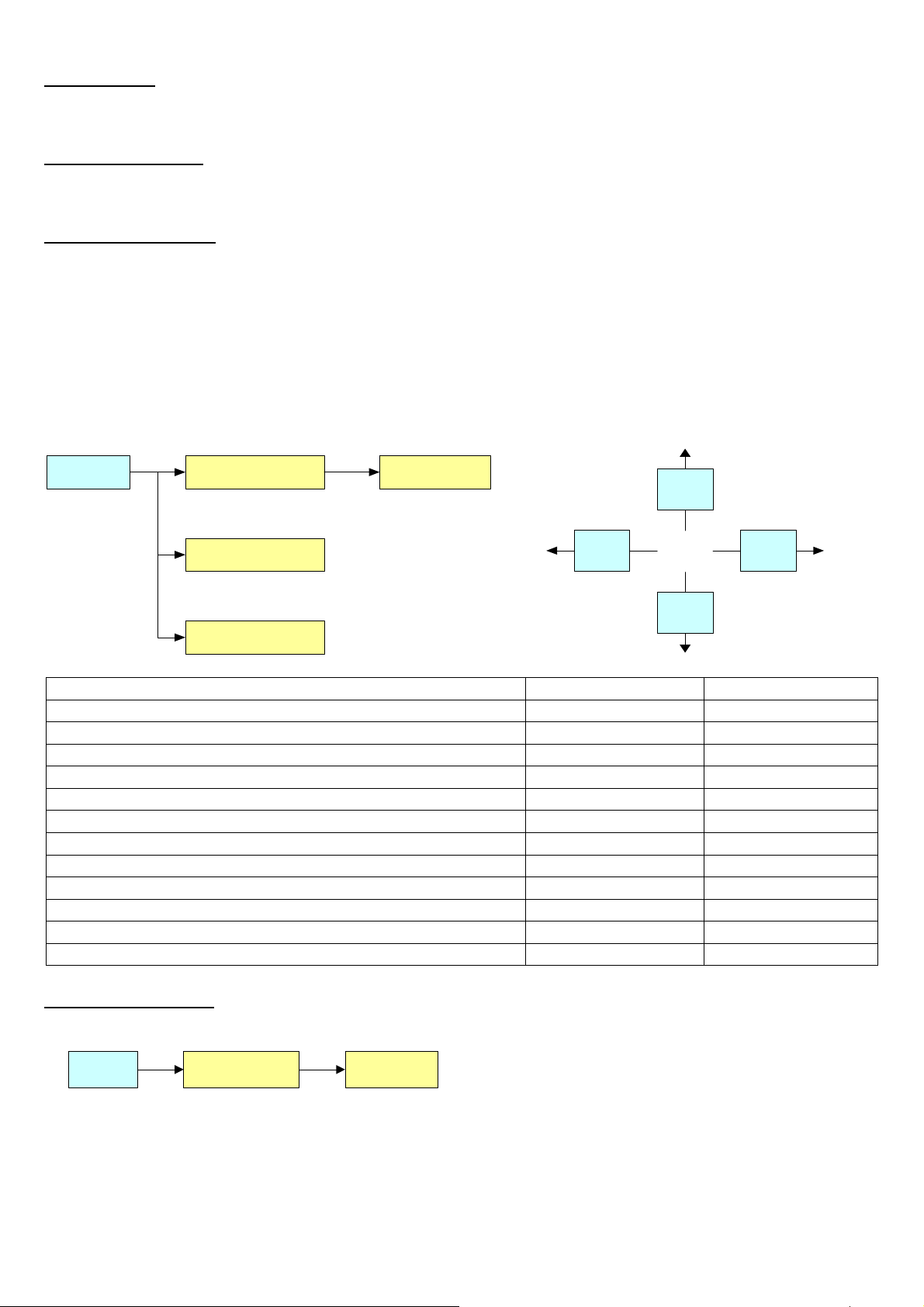
IPE100 indicator NU-IPE100-IO-USER-E-0212
GRAND TOTAL - Programmable printout By pressing the F10 key the PARTIAL TOTAL is printed and then cleared as well as the printing of the format linked to the
S.F.04 function.
START-UP PRINTOUT - Programmable printout -
When turning on the indicator, the printout of the format linked to the S.F.11 function is made; this function can be used, for
example, to unlock the pincers of the TM295 printer (when this last is turned on the pincers are always locked).
CALCULATOR RESULT - Programmable printout -
Once terminated the operation with the “CALCULATOR” function, the format linked to the S.F.12 function is printed. See
section 18.1.
14.1 LINKING OF THE FORMATS TO THE PRINT FUNCTIONS
Through function 200, combinable with the desired key (<< F.KEYS >> step, TECHNICAL MANUAL.), one accesses the
linking of the print formats (configurable in the SEtuP >> SEriAL >> Prn.FMt step TECHNICAL MANUAL.) to the 12
programmable print functions:
Print function Linked format
Fn 200
S.F. 01 (*) F. 01
...
S.F. 08
C
F7
ENTER
F6
Print Functions Key Linked step
PRINT KEY F5 S.F. 01
PARTIAL TOTAL F8 S.F. 02
GENERAL TOTAL F9 S.F. 03
GRAND TOTAL F10 S.F. 04
SINGLE WEIGH F6 or F7 S.F. 05
INPUT WEIGH F6 S.F. 06
OUTPUT WEIGH F7 S.F. 07
CUSTOMER TOTAL 2nd F followed by F1 S.F. 08
MATERIAL TOTAL 2nd F followed by F2 S.F. 09
VEHICLE TOTAL 2nd F followed by F3 S.F. 10
START-UP PRINTOUT Automatic entry S.F. 11
RESULT OF THE CALCULATOR Automatic entry S.F. 12
TO LINK THE FORMAT:
• Recall function 200, combinable with the desired key (<< F.KEYS >> step, TECHNICAL MANUAL.).
S.F. 01 F. 01200
• The LCD display shows:
S.F. XX in which:
XX indicates the number of the function (from 01 onwards) to which the print format is linked.
• Select the print function (for example S.F. 01) through the arrow keys and press the ENTER key.
• Once entered, the display shows:
42
Page 43

IPE100 indicator NU-IPE100-IO-USER-E-0212
XX in which:
XX indicates the number of the format to be linked.
• Type the format number and press ENTER.
NOTE: In order to no link any format to a vector one should enter the number 00.
14.1.1 QUICK LINKING OF THE FORMATS
By linking the number of a specific print function to the function 200 (preamble function in the << F.KEYS >> step,
TECHNICAL MANUAL.), it is possible to access directly to the modification of it with a direct key, for example F1 key to
quickly link the S.F. 1, and F2 key to quickly link the S.F. 2.
Furthermore for some print functions the desired formats can be quickly linked by setting directly the corresponding
code(function) to the desired key (<< F.KEYS >> step, TECHNICAL MANUAL.) without having to program the preamble:
CODE QUICK LINKING FUNCTION PRINT FUNCTION
200 Format linking to the Simple Printout (Prn.Fmt) S.F. 01
201 Format Linking to the Partial Total Printout (SND.FMT) S.F. 02
310 Format Linking to the Input Weigh Printout (FM.IN) S.F. 06
311 Format Linking to the Output Weigh Printout (FM.OUT) S.F. 07
312 Format Linking to the Single Weigh Printout (FM.SING) S.F. 05
TO QUICK LINK THE FORMAT:
• Recall the desired format, by pressing the linked key (<< F.KEYS >> step, TECHNICAL MANUAL.).
• The LCD display shows:
XX in which:
XX indicates the number of the format to be linked.
• Type the format number and press ENTER.
NOTE: In order to no link any format to a print function one should enter the number 00.
14.2 NUMBER OF TICKET COPIES
Through function 400, combinable with the desired key (<< F.KEYS >> step, TECHNICAL MANUAL.), any printout will be
made various times depending on the number set in this step (from 1 to 5).
14.3 REPETITION OF THE LAST EXECUTED PRINTOUT
By pressing in sequence the 2nd F and F5 keys the last executed printout is repeated; however, it’s not possible to reprint
any selected databases, and the date/time will be of the copy just reprinted.
NOTE: If one wants to execute more than one printout, it’s advisable to recall function 400 (see section 14.2).
14.4 STANDARD PRINTING FORMATS
The SEtuP >> SEriAL >> dEF.Prn parameter of the SETUP environment (TECHNICAL MANUAL.) allows to enable the
default printouts for the TPR printer.
NOTE: By enabling these printouts all the formatted print formats will be CANCELLED and will be SUBSTITUTED by the
standard formats, which automatically will be linked to the 12 print functions.
43
Page 44

IPE100 indicator NU-IPE100-IO-USER-E-0212
15. OTHER FUNCTIONS
15.1 CALCULATOR
Through function 114 combinable with the desired key (<< F.KEYS >> step, TECHNICAL MANUAL.), one enables the
calculator function.
• ADDITION
• MULTIPLICATION
• SUBTRACTION
Procedure:
- Enter the first value using the numerical keyboard.
- Press F1 to add, F2 to multiply, F3 to subtract the value.
Terminate the operation:
- TYPE the second value and PRESS ENTER: the result will be shown for a few seconds on the display.
- TYPE the second value and PRESS TARE: the result will be shown for a few seconds on the display and will be added
(if an addition and multiplication) or subtracted (if subtraction) to the current tare value.
- PRESS 2nd F: the NET weight on the scale will be used as a second value and the result will be shown for a few
seconds on the display.
In the end the printing of the “CALCULATOR” will be executed anyway (See section 14 PRINTOUTS).
To disable the calculator function, press the C key.
HELP FUNCTION
By pressing at length the . /HELP key it is possible to see the list of the keys used in the calculator function.
If one wants to scroll the list of the keys in manual mode, it is possible to use the arrow keys (F6 and F7 ).
15.2 DISPLAY OF NET WEIGHT WITH SENSITIVITY X 10 (for testing use during calibration)
By pressing at length the F2 key one will view the net weight with sensitivity times 10 (press again at length the F2 key to
return to the normal visualisation).
NOTES:
- With approved indicator, the visualisation lasts about 5 seconds, after which it’s disabled.
- The printout can only be done when the indicator has the standard sensitivity.
-
15.3 SETTING DATE / TIME
By pressing at length the F3 key ‘it’s possible to quickly access the setting from the date / time of the instrument:
DAY ENTER MONTH ENTER YEAR ENTER HOUR ENTER MINUTES ENTER.
15.4 SET-POINT FUNCTION
The indicator is fitted with a series of 4 signal outputs used for various types of operation, besides, through the I/O
expansion board (in the IO version) it is possible to use another 12.
In the SEtuP >>outPut >> r.ConF menu (TECHNICAL MANUAL) it is possible to set the characteristics of each output
which will be used: normally open or normally closed; upon direct control or weight stability, with hysteresis or without, the
functioning mode.
It is also possible to set whether the enabling of the output excludes the check on the previous outputs (see the SEtuP >>
outPut >> r.ModE parameter).
44
Page 45
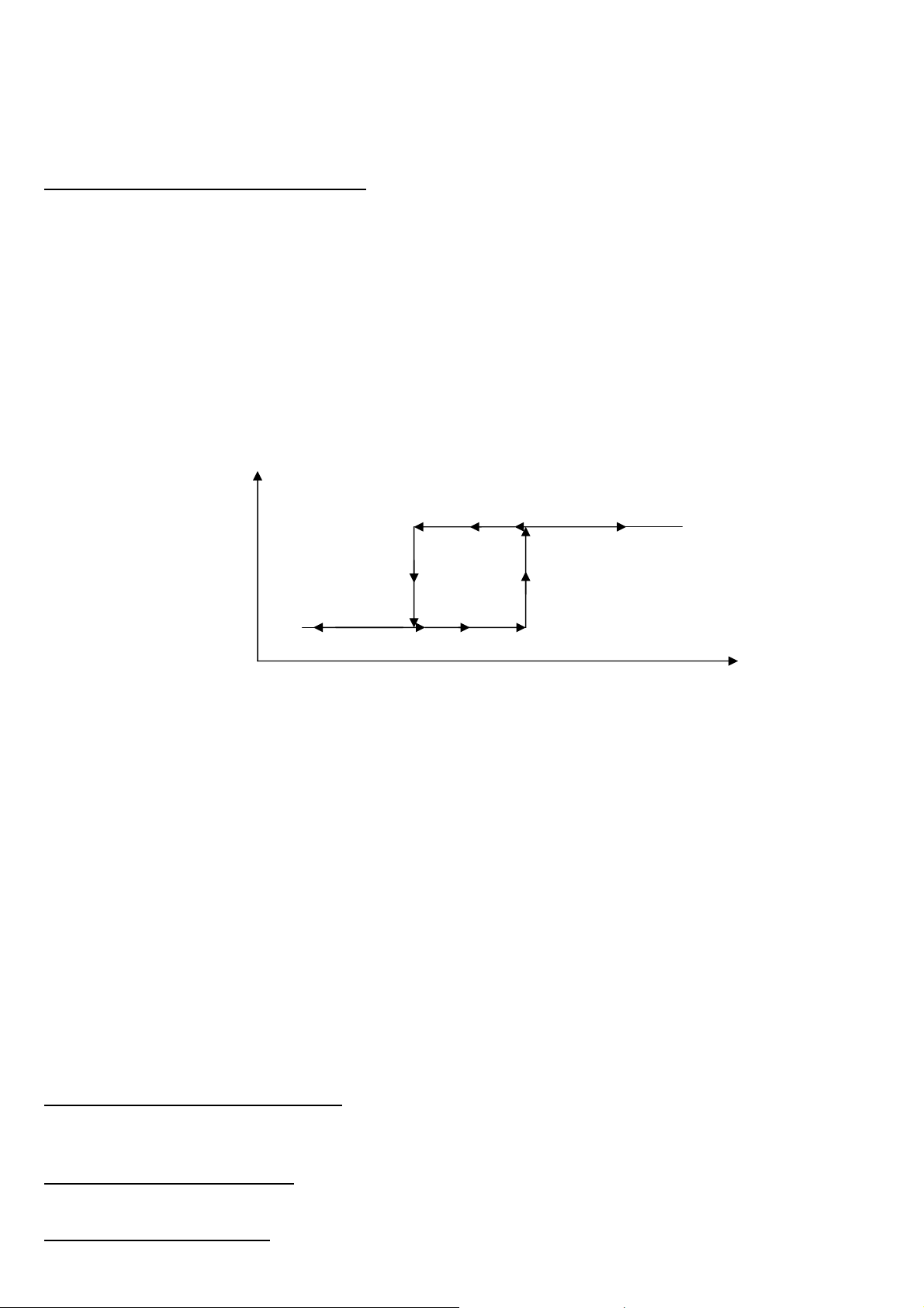
IPE100 indicator NU-IPE100-IO-USER-E-0212
15.4.1 NORMAL FUNCTIONING MODE
By setting the SEtuP >> outPut >> r.ModE parameter on “norMAL”, one configures the independent use of the outputs:
- the check is always made on all the set outputs
- the enabling of one of these does not provoke the disabling of the others.
15.4.1.1 SETPOINT ON THE GROSS WEIGHT
Functioning with hysteresis (rL.iSt “HYSTERESIS” parameter set as iSt.on)
By selecting this functioning mode the output function on the GROSS weight is activated; one enters two SET POINTS for
each output: a DISABLING one, which, when the gross weight is lower than it, disables the appropriate output; an
ENABLING one, which, when the gross weight is greater or equal than it, it enables the appropriate output. Through
function 202, combinable with the desired key (<< F.KEYS >> step, TECHNICAL MANUAL.), the SET POINT values are
entered (DISABLING and ENABLING) for each configured output:
- The display shows " S.1 on " (relay 1 ENABLING SETPOINT): press ENTER, enter the weight value with the keyboard
and confirm with ENTER (use the C key to quickly zero the current value).
- The display shows " S.1 oFF” (relay 1 DISABLING SETPOINT): press ENTER, enter the weight value with the keyboard
and confirm with ENTER (use the C key to quickly zero the current value).
- Proceed in the same way for the following outputs (if present).
- When finished programming the set points, exit with the C key.
OUT1 STATUS
ENABLED
DISABLED
S1on S1oFF
GROSS WEIGHT
Functioning without hysteresis (rL.iSt “HYSTERESIS” parameter set as iSt.oFF)
The operating mode is the same as the previous one, except that just one SETPOINT is entered for each output ("S.1 on“);
for this purpose the access to the " S.1 oFF " parameter is inhibited.
NOTES
- If all the outputs have the “NONE” (none) functioning mode, the enabling of the 202 function has no effect.
- The DISABLING SETPOINT must be less or equal to the ENABLING ones; if a value greater than the ENABLING one is
entered and confirmed in the DISABLING SETPOINT, the indicator will set at 0 the set point, until a correct value is
entered.
- If a value lower than the DISABLING one is entered and confirmed in the ENABLING SETPOINT, that value is
accepted, but the DISABLING SETPOINT is put at 0.
- The 0 value is valid on both the set point values.
- The SETPOINT check of the weight remains active on the present value even during the modification of the SET
POINT, until the new value is confirmed.
- At start-up, the relays are managed from when the weight is displayed and these take on the configuration set in the
SETUP environment. These are not managed inside the technical SETUP.
- In case of weight not valid (local or from remote scale) all the outputs will be disabled.
15.4.1.2 SETPOINT ON THE NET WEIGHT
By selecting this functioning mode, the output function on the NET weight is enabled; the entry of the SET POINTS and the
specifications are the same as the functioning mode on the gross weight.
15.4.1.3 GROSS WEIGHT AT ZERO
By selecting this functioning mode, the output function on the GROSS weight at 0 is enabled.
15.4.1.4 NET WEIGHT AT ZERO
By selecting this functioning mode, the output function on the NET weight at 0 is enabled.
45
Page 46
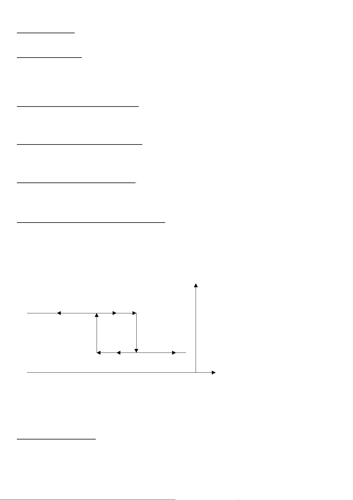
IPE100 indicator NU-IPE100-IO-USER-E-0212
15.4.1.5 INSTABILITY
By selecting this functioning mode, the output function on the unstable weight is enabled.
15.4.1.6 TOTALISATION
By selecting this functioning mode, the output function is enabled after executing a single weigh or after an output weight (at
the end of an input/output cycle); the output remains enabled until the weigh is restored; in other words, by the passing by
zero of the net weight or by weight instability (see F.ModE >> rEACt “REACTIVATIONS” parameter of the TECHNICAL
SETUP, TECHNICAL MANUAL.).
15.4.1.7 SETPOINT ON THE PARTIAL TOTAL
By selecting this functioning mode, the output function is enabled on the sum between the NET weight on the scale and the
accumulated net partial total; the entry of the SET POINTS and the specifications are the same as the functioning mode on
the gross weight.
15.4.1.8 SETPOINT ON THE GENERAL TOTAL
By selecting this functioning mode, the output function is enabled on the sum between the NET weight on the scale and the
accumulated net general total; the entry of the SET POINTS and the specifications are the same as the functioning mode
on the gross weight.
15.4.1.9 SETPOINT ON THE GRAND TOTAL
By selecting this functioning mode, the output function is enabled on the sum between the NET weight on the scale and the
accumulated net grand total; the entry of the SET POINTS and the specifications are the same as the functioning mode on
the gross weight.
15.4.1.10 SETPOINT ON THE NEGATIVE NET WEIGHT
Functioning with hysteresis (rL.iSt “HYSTERESIS” parameter set as iSt.on)
By selecting this functioning mode the outputs function on the NEGATIVE NET weight is activated; one enters two
NEGATIVE SET POINTS for each output: a DISABLING one, which, when the NET weight is greater than it, disables the
appropriate output; an ENABLING one, which, when the NET weight is lower or equal than it, it enables the appropriate
output.
The entry and specifications are the same for the functioning mode on the gross weight.
OUT1 STATUS
ENABLED
DISABLED
S1.on S1.Off NET WEIGHT
Functioning without hysteresis (rL.iSt “HYSTERESIS” parameter set as iSt.oFF)
The operating mode is the same as the previous one, except that just one SETPOINT is entered for each output (" S.1 on
“); for this purpose the access to the " S.1 oFF " parameter is inhibited.
The entry and specifications are the same for the functioning mode on the gross weight.
15.4.1.11 OPERATION MADE
By selecting this functioning mode, the output function is enabled after the execution of an input or output weigh; the relay
remains enabled until the weigh is restored; in other words, by the passing by zero of the net weight or by weight instability
(see F.ModE >> rEACt “REACTIVATIONS” parameter of the TECHNICAL SETUP, TECHNICAL MANUAL.).
46
Page 47
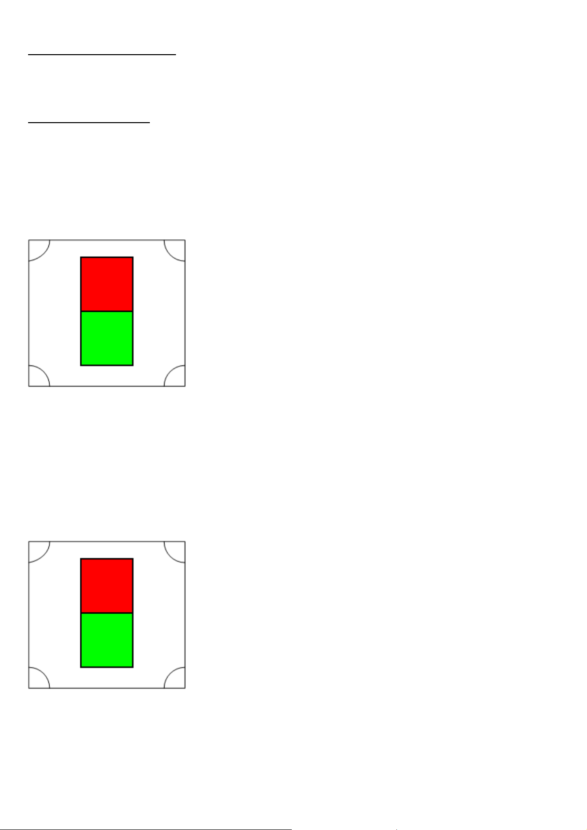
IPE100 indicator NU-IPE100-IO-USER-E-0212
15.4.1.12 WEIGHT ACQUISITION
By selecting this functioning mode, the output function is enabled after the weight acquisition; the relay remains enabled
until the weigh is restored; in other words, by the passing by zero of the net weight or by weight instability (see F.ModE >>
rEACt “REACTIVATIONS” parameter of the TECHNICAL SETUP, TECHNICAL MANUAL.).
15.4.1.13 CONTROL LIGHT
By selecting this functioning mode the output function on the NET weight is enabled: when the net weight is equal or
greater than the ENABLING SET POINT, the relay is disabled.
The relay is disabled until the execution of an input or output weight; after this, the relay is activated and remains activated
until the weight is lower than the ENABLING SET POINT, and the weight doesn’t surpass it once again.
If the relay is disabled and no input or output weight is made, the functioning is the same as that of the set point on the net
weight.
FUNCTIONING WITH 1 CONTROL LIGHT:
RED R1, functioning with control light, normally CLOSED,
ENABLING SET POINT 10kg.
GREEN R2, functioning with control light, normally OPEN,
ENABLING SET POINT 10kg.
• The scale is unloaded and the vehicle is not yet positioned on the scale: the GREEN light turns on.
• The vehicle is now positioned on the scale. When the ENABLING SET POINT is reached, the GREEN light turns off
and the RED light turns on.
• After the execution of the input or output weight, the RED light turns off and the GREEN light turns back on.
• The vehicle descends from the scale and the GREEN light continues to stay on.
• It is possible to execute another input/output weigh with the same procedure.
FUNCTIONING WITH 2 CONTROLS LIGHT:
The functioning mode with 2 independents controls light is equal to the functioning previously described, with the difference
that it’s possible to manage 2 independents scales, each with one different control light.
SCALE 1
RED R1, functioning with control light, normally CLOSED,
ENABLING SET POINT 10kg.
GREEN R2, functioning with control light, normally OPEN,
ENABLING SET POINT 10kg.
47
Page 48
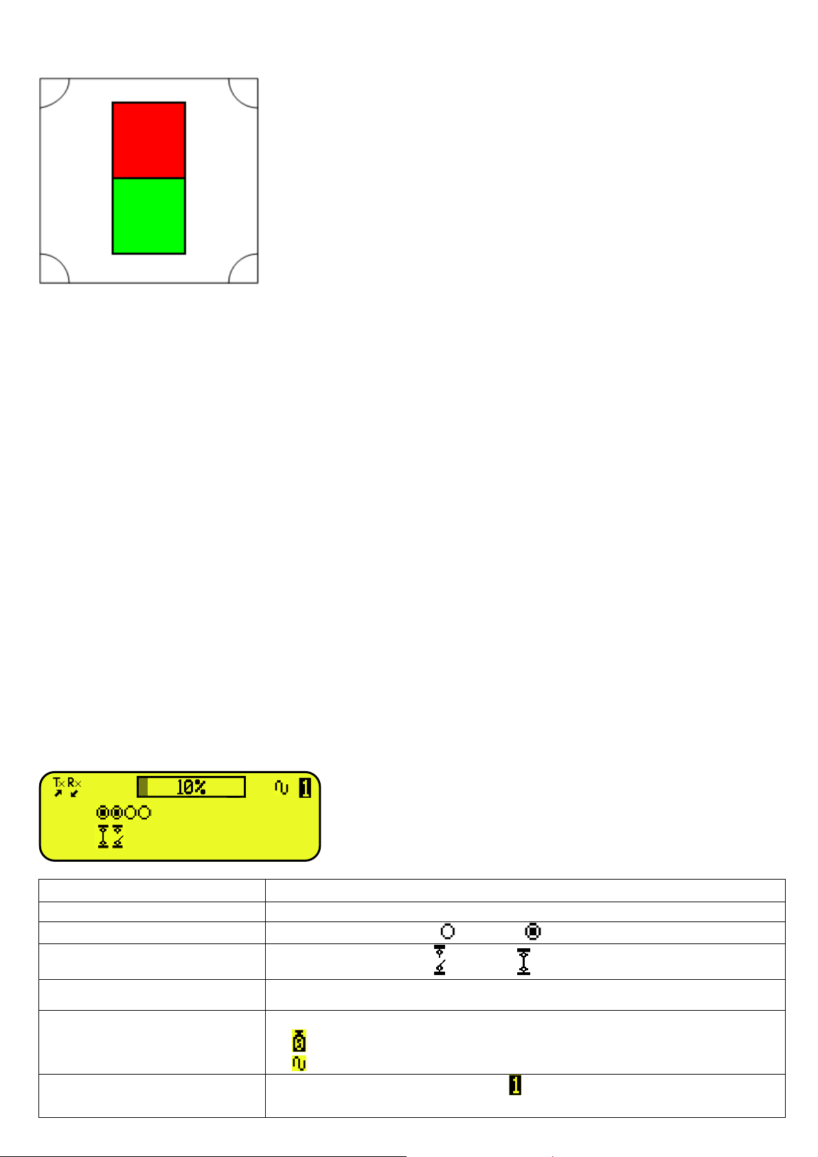
IPE100 indicator NU-IPE100-IO-USER-E-0212
SCALE 2
RED R3, functioning with control light for the second scale,
normally CLOSED, ENABLING SET POINT 10kg.
GREEN R4, functioning with control light for second scale,
normally OPEN, ENABLING SET POINT 10kg.
15.4.2 EXCLUSIVE FUNCTIONING MODE
By setting the SEtuP >> outPut >> r.ModE parameter on “EXCLuS”, one configures the exclusive use of the outputs:
- The check is made on all the set outputs starting from the last one (OUT16) to the first one (OUT1).
- When one of these is enabled the check on the previous ones is excluded.
By selecting this functioning mode and setting the set points in increasing order, one can create outputs activation ranges.
Example:
RELAY SETPOINT ACTIVATION RANGE
rL. 1 1.000 kg From 1.000 to 1.999
rL. 2 2.000 kg From 2.000 to 2.999
rL. 3 3.000 kg From 3.000 to 3.999
rL. 4 4.000 kg From 4.000 onwards.
In this case, if the weight reaches 2.500 kg, ONLY THE “rL. 2” OUTPUT IS ENABLED; if the weight reaches 4.500 kg,
ONLY THE “rL. 4” OUTPUT IS ENABLED.
15.4.3 QUICK MODIFICATION OF THE SETPOINTS
By linking the number of a specific setpoint to the function 202 (preamble function in the << F.KEYS >> step, TECHNICAL
MANUAL.), it is possible to access directly to the modification of it with a direct key, for example F1 key to quickly modify
the SETPOINT 1, and F2 key to quickly modify the SETPOINT 2.
15.5 DIAGNOSTIC PERIPHERALS
Through function 118 combinable with the desired key (<< F.KEYS >> step, TECHNICAL MANUAL.), one enables the
diagnostic peripherals function.
The display shows:
A.O.
OUT
IN
10.000 kg
STATUS DESCRIPTION
ANALOGIC OUTPUT(A.O) Analogue output value express as a percentage.
OUTPUTS (OUT)
Status output, non active ( ) or active ( ).
INPUTS (IN)
Status input, non active ( ) or active ( ).
SERIAL COMUNICATIOS (Tx RX) The serial communication is active with external device.
Status of the weight:
WEIGHT
- unloaded scale;
- unstable weight;
SCALE
Number of the active scale ( example , see section 5 SCALE SELECTION) and
the relative weight loaded.
48
Page 49
IPE100 indicator NU-IPE100-IO-USER-E-0212
15.6 COM DATA DIAGNOSTIC
Through function 119 combinable with the desired key (<< F.KEYS >> step, TECHNICAL MANUAL.), one enables the
Com data diagnostic function. The display shows:
119 COM. DAT
● COM1 (PC)
○ COM2 (PRN)
In the first screen one selects the port on which the diagnostic control should be executed. While in the second screen, one
selects the code that one wants to use for viewing the data in transit.
RX: READ<0D><0A> R
A
TX: ST, GS, 1.037,Kg<0D><0A>
When the data on the RX and TX reception and transmission lines are correctly displayed, then the functioning of the
relative serial line is considered to be correct.
NOTE: By pressing the ./HELP key, it’s possible to see the keys list used in the menu.
119 COM. DAT
● ASCII
○ BINARY
16. ALIBI MEMORY
The alibi memory allows storing the executed weighs or the weights transmitted to the PC.
The stored values can then be recalled by the PC serial line or directly on the indicator’s LED display for a following check.
The data filed with each weigh or upon each weight transmission is:
- Gross weight
- Tare
- Unit of measure
- Number of selected scale
The memorisation of a weigh takes place:
• Following the reception of a command through the serial line, See section 16.2.1.
• Upon the printing made with the F5 key or upon totalisation
By setting the SEtuP >> SEriAL >> CoMPrn >> ProtoC parameter on "Alibi" (TECHNICAL MANUAL.)
It’s possible also to transmit the string (weigh/ID) on the PC port, by setting the SEtuP >> SEriAL >> CoMPC >>
ProtoC parameter on "Alibi" (TECHNICAL MANUAL.);
The string is transmitted in the same format of the string received in response to the “WEIGHT VALUE REQUEST
WITH WEIGH ID” command, described in section 16.2.1
The identification of the weigh takes place through the ID code; a code is given to each weigh, allowing finding the weigh in
the database.
If the weight can be saved in the alibi, the numeric ID will be substituted with the message "NO".
The ID has the following format:
<Rewriting number > — < Weigh number >
- Rewriting number: number of 5 digits which may go from 0 to 00255; it indicates the number of complete rewritings of
the alibi memory.
- Weigh number: number of 6 digits which may go from 0 to 131071; it indicates the weigh number in the current rewriting
of the alibi memory
49
Page 50

IPE100 indicator NU-IPE100-IO-USER-E-0212
With each storage, the weigh number is increased of 000001; when it reaches the value 131071, it restarts from 000000
and the rewriting number increases of 00001.
If the weigh can not be saved in the alibi, the numeric ID will be substituted with the message "NO".
For example:
If the weigh which has been stored is the following:
“PIDST,1, 1.000kg, 1.000kg,00126-131071”
the following will be:
“PIDST,1, 1.000kg, 1.000kg,00127-000000”
NOTE: it’s possible to read the last 131071 weighs.
16.1 READING OF THE WEIGHS CARRIED OUT
Through function 427, combinable with the desired key (<< F.KEYS >> step, TECHNICAL MANUAL.) it’s possible to read
a carried out weigh:
first enter the rewriting number of the Alibi memory (rEW.id), confirm with ENTER, and then enter the weigh number (id)
and press ENTER. The ID is accepted only if valid.
If the alibi memory is empty the message “EMPTY” appears on the LCD display for a few instants; if the ID code entered is
not valid, the “no id” message appears for a few instants, and then one exits the step.
By entering a valid ID code, the LCD display shows the following data, selectable through the arrow keys :
Ch.X in which X is the selected channel number (from 0 to 4)
Gross weight value with unit of measure;
Tare weight value with unit of measure;
Press C to exit the reading state of the weighs.
NOTE: It is possible to read the weigh carried out also through the PC serial line (see the “WEIGH READING” serial
command in the following section).
16.2 SERIAL COMMANDS FOR MANAGING THE ALIBI MEMORY:
!! IMPORTANT !!
If the serial commands are transmitted in the format:
<ESC> command <STX>
in which: <ESC> is the ASCII decimal 27 character
<STX> is the ASCII decimal 02 character
Also the relative answer will be:
<ESC> string <STX>
16.2.1 REQUEST WEIGHT VALUE WITH WEIGH ID
The command which allows saving the weight in the alibi memory and the transmission is:
<II>PID<CRLF>
< II > = machine code, only if functioning in 485
PID = saving command of the weight data in the alibi memory
CR = ASCII 13 decimal code
LF = ASCII 10 decimal code
If the gross weight is equal or greater than zero and stable, the instrument will save the current weight in the alibi memory.
And the PID string (weight/id) will be transmitted on the PC port; this is described in the following section.
50
Page 51

IPE100 indicator NU-IPE100-IO-USER-E-0212
16.2.2 STRING FORMAT (WEIGHT/ID)
The PID string contains all the information regarding the executed weigh.
DESCRIPTION OF THE PID STRING:
[II]PIDSS,B,LLLLLLLLLLUU,YYTTTTTTTTTTUU,(ID | NO) <CR or CRLF>
in which: [II] 485 address (only in the case of 485 transmission mode)
SS US instable weight
ST stable weight
OL weight out of range (greater)
UL weight out of range (lower)
, comma character, ASCII 044
B number of selected channel
, comma character, ASCII 044
LLLLLLLLLL gross weight on 10 digits
UU unit of measure
, comma character, ASCII 044
YY 2 spaces in the case of null tare or semiautomatic tare, PT in the case of preset tare
TTTTTTTTTT tare weight on 10 digits
, comma character, ASCII 044
ID XXXXX-YYYYYY or “NO”: weigh not stored in the alibi memory; the gross weight is
negative or unstable.
<CR or CRLF> Terminator, ASCII 13 and ASCII 10 characters
16.2.3 WEIGH READING
Command:
[II]ALRDXXXXX-YYYYYY <CR o CRLF>
in which [II] 485 address (only in the case of 485 transmission mode)
XXXXX rewriting number, from 0 up to 255.
- ASCII 045 character
YYYYYY ID code
<CR o CRLF> terminator, ASCII 13 and ASCII 10 characters
Instrument answer:
[II]B,LLLLLLLLLLUU,YYTTTTTTTTTTUU <CR o CRLF>
in which: [II] 485 address (only in the case of 485 transmission mode)
B number of selected channel
, comma character, ASCII 044
LLLLLLLLLL gross weight on 10 digits
UU unit of measure
, comma character, ASCII 044
YY 2 spaces in the case of null tare or semi automatic tare, PT in the case of preset tare
TTTTTTTTTT tare weight on 10 digits
<CR o CRLF> Terminator, ASCII 13 and ASCII 10 characters
16.2.4 ALIBI MEMORY CANCELLATION (only with non approved instrument)
Command:
[II]ALDL <CR o CRLF>
in which [II] 485 address (only in the case of 485 transmission mode)
Instrument answer:
[II]ALDLOK <CR o CRLF> if the cancellation has been carried out effectively
[II]ALDLNO <CR o CRLF> if the cancellation has not been carried out effectively
51
Page 52

IPE100 indicator NU-IPE100-IO-USER-E-0212
17. MESSAGES
While using the indicator, it is possible to incur into the following errors:
17.1 INSIDE THE SETUP OR MENU OR AT START-UP
VISUALIZATION DESCRIPTION
During the calibration some internal negative points have been calculated:
- the calibration point is less than the zero point.
- the signal is negative (check the connections)
Err. – 36
CALIBRATION
ERROR
During the calibration some internal points less than the minimum value have
Err. – 37
CALIBRATION
ERROR
been calculated:
- the calibration point is equal to the zero point.
- A capacity too high in relation to the division has been set.
Err. – 38
CALIBRATION
ERROR
Range not valid: please check that RANGE 1 < RANGE 2 < RANGE 3.
Err. – 39 Range not valid: please check that RANGE 1 < RANGE 2 < RANGE 3.
Invalid calibration range number (there is the value 0 or values greater than
Err. – 39
NO CALIBRATION
3); one must execute a TECHNICAL DEFAULT (dFLt.t parameter of the
SETUP environment), if not already executed previously, and carefully carry
out the calibration.
Err. – 72
Err. – 85
Equalization coefficient adjustment not allowed because a too low sample
weight has been used.
Equalization coefficient adjustment not allowed because the instrument has
not been calibrated.
It is shown when, during the sampling phase, the weight results to be unstable
Err.Mot
ERROR: UNSTABLE
WEIGHT
and therefore can not be acquired.
By pressing a key it is required to press ENTER to retry, C to exit or 1 to
accept the unstable value detected.
ErPnt
SAVE ?
EXITING SETUP:
SAVE ?
SURE?
During the acquisition of a calibration point, a null value from the converter
has been read.
The instrument requests the saving when exiting the SETUP; press ENTER to
confirm or C to not continue.
The instrument requests a confirmation before proceeding: press ENTER to
confirm or C to not continue.
Generic error. Possible motives can be:
- Division not valid: please check that DIVISION 1 < DIVISION 2 <
Error
DIVISION 3;
- An error has taken place in the connection, configuration, equalisation,
calibration of the cells, etc.
ERROR SX
CELL Y
It is shown when there is an error in the communication with the X scale – Y
cell : check the connections and communication parameters (TECHNICAL
MANUAL.).
NOTE: if the Er – XX error appears after the indicator start-up; press the TARE key to enter in the SETUP
environment.
52
Page 53

IPE100 indicator NU-IPE100-IO-USER-E-0212
17.2 IN WEIGHING
MESSAGE DESCRIPTION
WEIGHT UNDER
20 DIVISIONS
NO ZERO CROSS OR
INSTABILITY
*** POWER OFF *** Turning off of the instrument through the key (see section 3.3).
“- OUT CAPACITY ! –“
ZERO Execution of scale zero (see section 6).
TARE Tare execution (see section 7).
CLEAR Tare cancellation (see section 7.4)
prn-on Turning on printer for maintenance (see section 3.5).
GROSS Visualisation of the gross weight.
NET Visualisation of the net weight.
LOCK Tare lock or enabled keyboard function.
UNLOCK Tare lock or disabled keyboard function.
Low.Batt Indicates that the battery is discharged (voltage at minimum level).
PRINTER ERROR:
CHECK THE CTS!
It is shown in the LCD display when one tries to print or totalise with the 0 or negative weight.
Printing or totalisation not possible without having the weight pass by the net zero or by
instability.
OVERLOAD
The weight is 9 divisions above the Maximum Capacity.
OR
UNDERLOAD
- Approved instrument:
The weight is under the gross zero (-100 divisions).
- Non approved instrument:
The weight is under the gross zero (- capacity – 9 divisions).
Error during the printing: totalisation not possible or printing not executed / finished.
USER - PRESS KEY See section 12.
ERROR SX
CELL Y
It is shown when there is an error in the communication with the X scale – Y cell : check the
connections and communication parameters for digital load cells (TECHNICAL MANUAL.).
53
Page 54

IPE100 indicator NU-IPE100-IO-USER-E-0212
DECLARATION OF CONFORMITY
This device conforms to the essential standards and norms relative to the
applicable European regulations.
WARRANTY
The warranty period begins on the day the instrument is delivered. It includes
spare parts and labour for repairs at no charge if the INSTRUMENTS ARE
RETURNED prepaid to the DEALER’S PLACE OF BUSINESS. Warranty covers
all defects NOT attributable to the Customer (such as improper use) and NOT
caused during transport.
If on site service is requested (or necessary), for any reason, where the instrument
is used, the Customer will pay for all of the service technician’s costs: travel time
and expenses plus room and board (if any).
The customer pays for shipping costs (both ways), if the instrument is shipped to
the DEALER or manufacturer for repair.
The WARRANTY is VOIDED if faults occur due to work done by unauthorised
personnel or due to connections to equipment installed by others or incorrect
connection to the power supply.
This warranty DOES NOT provide for any compensation for losses or damages,
direct or indirect, incurred by the Customer due to complete or partial failure of
instruments or systems sold, even during the warranty period.
AUTHORISED SERVICE CENTRE STAMP
54
 Loading...