

Page 1
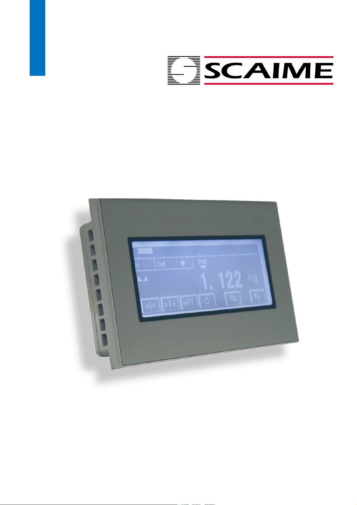
User Manual
eNodTouch
Touch screen for eNod4 controllers
NU-eNodTouch-E-0413
SCAIME SAS – Technosite Altéa –BP501- 74105 ANNEMASSE Cedex
Tél. : +33 (0)4 50 87 78 64 – www.scaime.com
Page 2

Contents
1. Hardware ................................................................................................................... 3
1.1. Presentation ................................................................................................................. 3
1.2. Installation ................................................................................................................... 4
1.2.1. Installation requirements ..........................................................................................................4
1.2.2. eNodTouch installation .............................................................................................................4
1.3. Electrical powering ....................................................................................................... 5
1.4. RS485 interface for connection to eNod4 ...................................................................... 5
2. Off-Line setting .......................................................................................................... 6
2.1. Entering Offline mode .................................................................................................. 6
2.2. Offline mode operations ............................................................................................... 6
2.2.1. Main unit Menu .........................................................................................................................7
2.2.2. Brightness/contrast control .......................................................................................................7
2.2.3. Device/PLC Menu ......................................................................................................................8
2.2.4. Password menu .........................................................................................................................8
2.2.5. Initialize menu ...........................................................................................................................8
2.2.6. Maintenance menu ...................................................................................................................9
3. On-Line Functioning ................................................................................................... 9
3.1. Startup screens............................................................................................................. 9
3.2. Main screen ............................................................................................................... 10
3.2.1. Transmitter mode (eNod4-T, eNod4-C, eNod4-D) ..................................................................10
3.2.2. Checkweigher mode (eNod4-C) ...............................................................................................10
3.2.3. Dosing mode (eNod4-D) ..........................................................................................................10
3.2.4. Keyboard functions ..................................................................................................................11
3.3. Result displaying and storage (eNod4-C, eNod4-D) ...................................................... 11
3.4. Main setup menu ....................................................................................................... 12
3.4.1. eNodTouch setup ....................................................................................................................12
3.4.2. Calibration setup .....................................................................................................................13
3.4.3. I/O Setup ..................................................................................................................................14
3.4.4. Configuration Setup .................................................................................................................15
3.4.5. Function mode setup (eNod4-C & eNod4-D) ..........................................................................16
3.5. Checkweigher Setup menu (eNod4-C) ......................................................................... 16
3.6. Dosing Setup menu (eNod4-D) .................................................................................... 17
3.6.1. Dosing Cycle Setup ..................................................................................................................17
3.6.2. Starting conditions setup .........................................................................................................18
3.6.3. Dosing Timing Setup ................................................................................................................18
3.6.4. In-flight correction Settings .....................................................................................................19
3.6.5. Flow rate control settings ........................................................................................................19
3.6.6. Dosing Tolerance control .........................................................................................................19
3.7. Dosing Target values .................................................................................................. 20
2
User manual SCAIME:
NU-eNodTouch-E-0413
Page 3
1. Hardware
1.1. Presentation
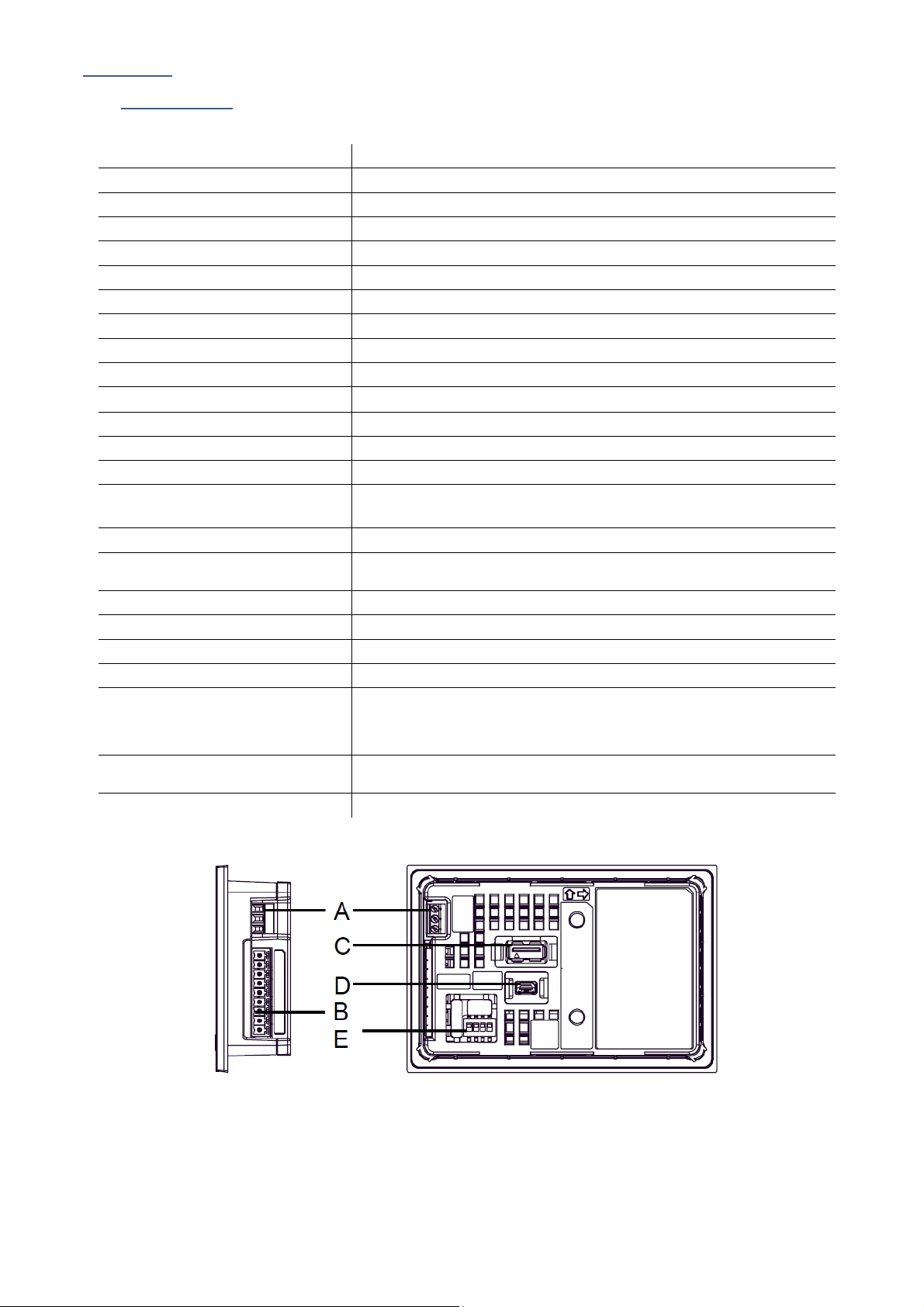
eNodTouch, is a compact graphic operator interface with the following specifications:
Display type Back lighted 3.4” STN Monochrome LCD
Resolution W200 x H80 pixels
Display area W80 x H40 mm
Display colours Monochrome White/Red/Pink (16 Levels)
Backlight White/Red LED
Brightness / Contrast 16 levels / 8 Levels
Touch Panel type Resistive film, resolution 1024x1024
Touch panel service life 1,000,000 times or more
Input voltage 24VDC, 6.2W or less
Rated voltage DC 19.2 to 28.8V
Insulation resistance
Grounding Grounding resistance of 100Ω, 2mm² or thicker wire
Dimension W116.5 x H77.5 x D28mm
Weight 0,2 kg approx.
Panel cut dimension W105 x H66 mm
Surrounding air temperature 0 to +50°C
Ambient humidity 10 to 90 % RH (Wet bulb temperature: 39 ℃ or less - no
Dust 0.1 mg/m³ or less (non-conductive levels)
Storage temperature -20 to +60°C
Structure IP65, on the front panel when properly installed in an enclosure
Cooling method Natural air circulation
Serial Interface COM1 RS-422/485, Asynchronous Transmission, Data Length: 7 or 8 bit,
USB1 interface Conforms to USB2.0 (Type A), Power Supply Voltage: DC 5 V ±5 %,
USB2 interface Conforms to USB2.0 (mini-B), Communication Distance: 5 m or less
DC 500V, 10MΩ
Panel thickness area: 1 to 5 mm
condensation.)
Parity: none, Odd or Even, Stop Bit: 1 or 2 bit, Data Transmission
Speed: 2,400 bps to 115.2 kbps, Communication Distance: 30 m or
less
Communication Distance: 5 m or less
(A) Power Connector
(B) Serial Interface (COM1)
(C) USB (Type A) Interface (USB1)
(D) USB (mini B) Interface (USB2)
(E) DIP Switch (SW1)
3
User manual SCAIME:
NU-eNodTouch-E-0413
Page 4
1.2. Installation
Installation requirements
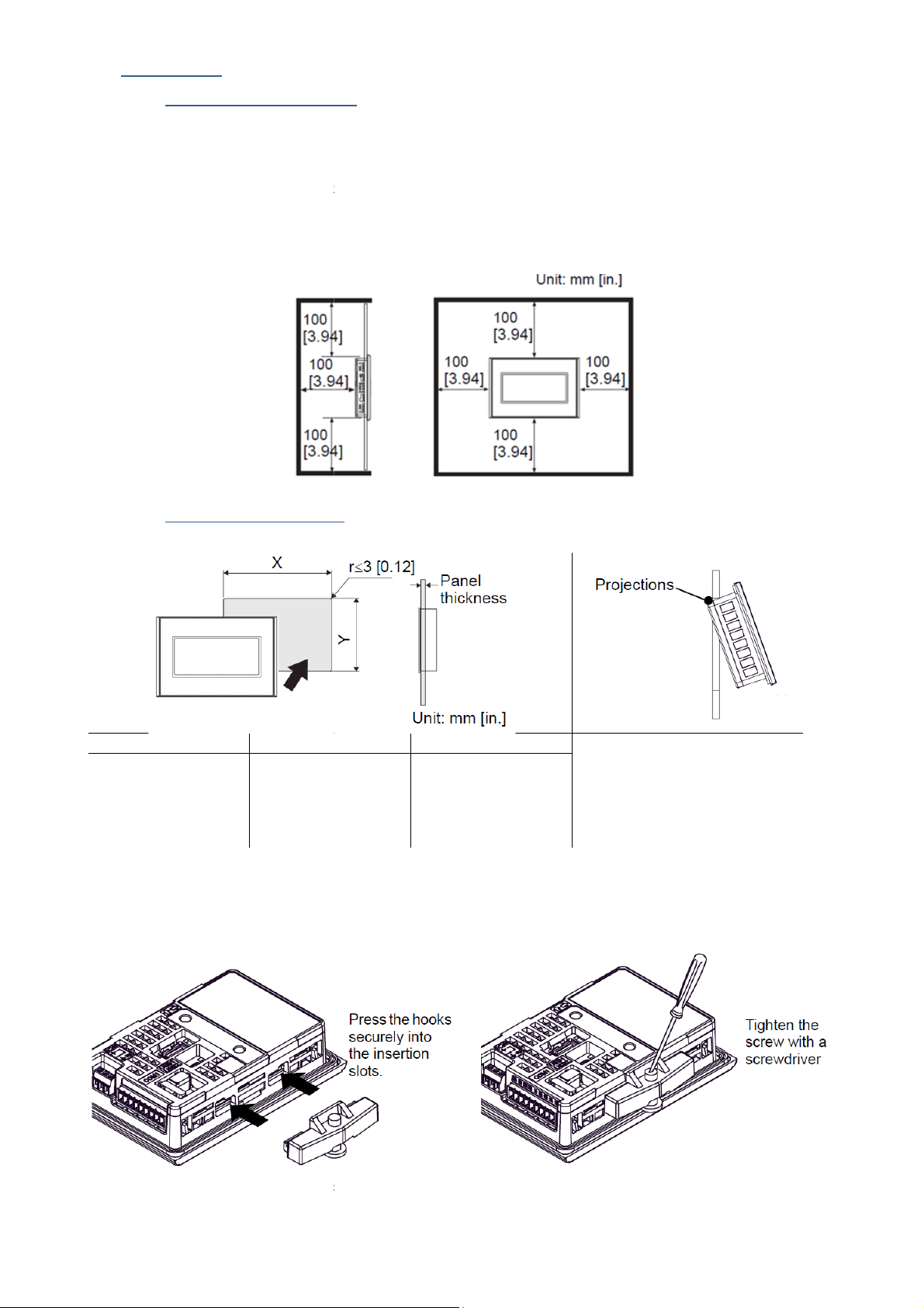
For easier maintenance, operation, and improved ventilation, be sure to install
away from adjacent structures and other equipment.
Be sure that the surrounding air temperature and the ambient humidity are within their des
(Surrounding air temperature: 0 to 50°C, Ambient humidity: 10 to 90%RH, Wet bulb temperature: 39°C max.) When
on the panel of a cabinet or enclosure,
et or enclosure’s internal
eNodTouch installation
66.0
[2.60
Cut a hole in the panel according to the
Confirm that the installation gasket is attached
d that you use the installation
Press the installation fastener hooks securely
Tighten the installation fasteners with a screwdriver. There are two insertion slots on both the
eNodTouch
“Surrounding air temperature” indicates both the
has two projections
on the top to prevent falling
during installation. Please insert
the unit into the panel at an
angle to avoid hitting the
projections.
the unit into
t absorbs vibration in addition
1.2.1.
•
•
installing eNodTouch
face and cabin
1.2.2.
temperature.
at least 100mm [3.94in.]
ignated ranges.
panel
X Y
105.0
[4.13]
•
]
eNodtouch cutout dimensions.
•
•
It is strongly recommende
Panel thickness eNodTouch
1.0 [0.04]
To 5.0 [0.20]
to eNodTouch unit and then place
gasket, since i
the Panel from the front.
to repelling water.
•
•
User manual SCAIME:
into the insertion slots on eNodTouch.
top and bottom.
4
NU-eNodTouch-E-0413
Page 5
1.3. Electrical powering
•
Supplying a power voltage other than that specified will damage the power source and the unit.
•
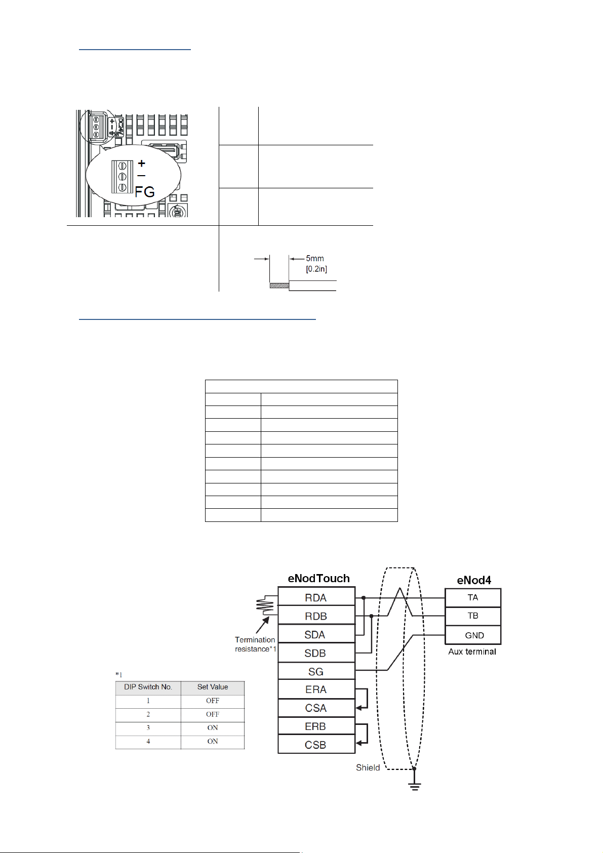
When the FG terminal is connected, be sure the wire is grounded.
+
-
Grounding Terminal
Conductor type
FG
to eNodTouch chassis
Simple Wire: 0.75 to 1.5mm2
Stranded Wire: 0.75 to 1mm2
1.4. RS485 interface for connection to eNod4
•
The serial interface is not isolated. Always connect the SG (Signal Ground) of the unit to the connected device.
•
SG (Signal Ground) and FG (Frame Ground) are connected internally
RS422/RS485 terminal Block
Label Meaning
CSB Send Possible B (-)
CSA Send Possible A (+)
ERB Data Terminal Ready B (-)
ERA Data Terminal Ready A (+)
SG Signal Ground
RDB Receive Data B (-)
RDA Receive Data A (+)
SDB Send Data B (-)
SDA Send Data A (+)
•
A terminating resistor can be inserted using the DIP Switch (4-bit) on the rear of the RS-422/485 type. Factory default
settings are all set to “OFF” (no terminating resistor).
24V
0V
connected
5
User manual SCAIME:
NU-eNodTouch-E-0413
Page 6
2. Off-Line setting
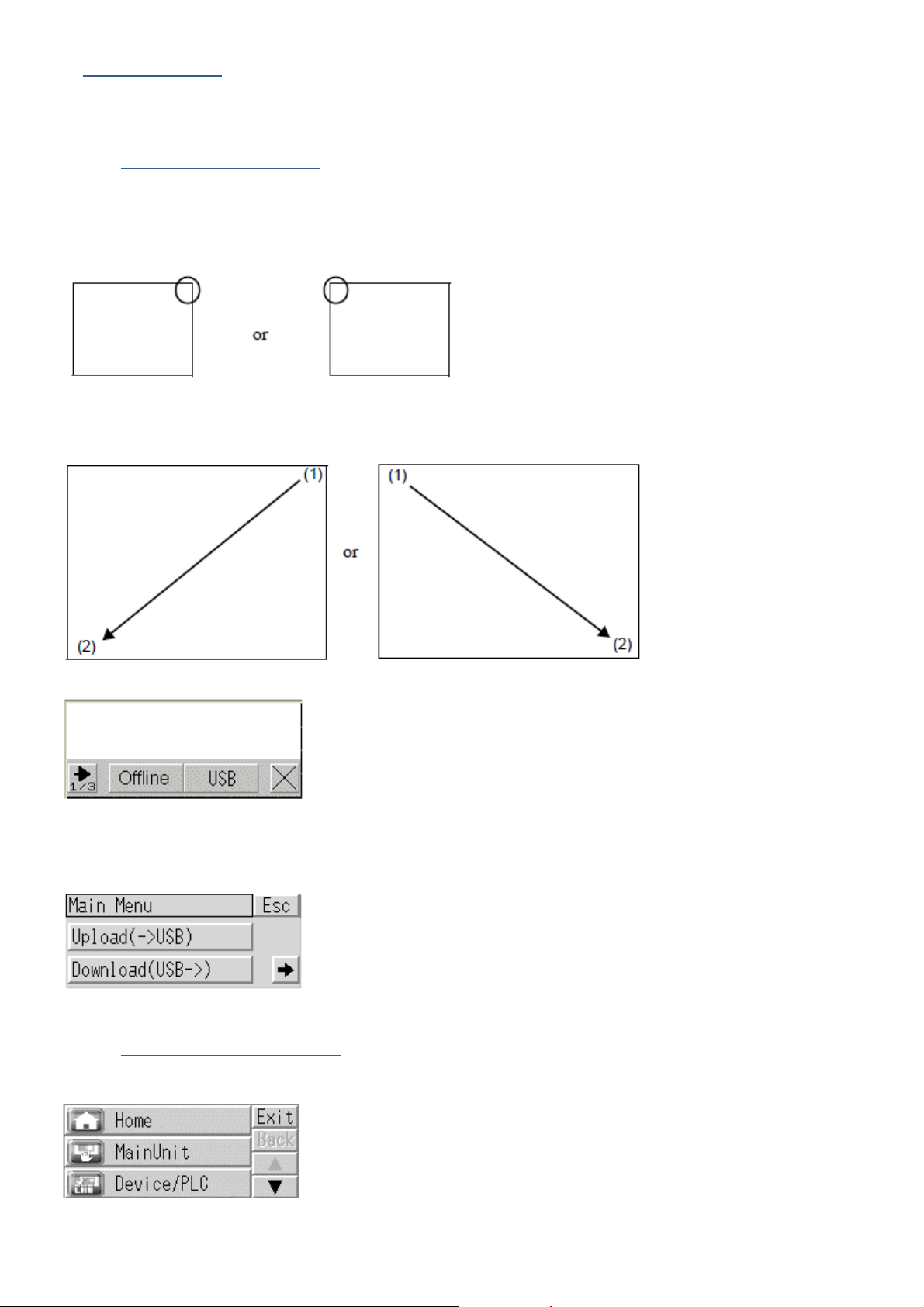
Offline mode provides access to system settings, self diagnostics, and so on. Use offline mode to set up the display unit before
use.
2.1. Entering Offline mode
At Power ON
Touch the upper right corner or upper left corner (within 40 pixels of the edges) of the panel for at least 3 seconds soon after the
startup screen is displayed.
When Operating
Touch the upper right then bottom left corners, or the upper left and bottom right corners of the panel (within a 40 pixel area) in
0.5 seconds.
When the system menu is displayed, touch the [Offline] button
•
Touch [Offline] to go to Offline mode
•
Touch [USB] to start the USB memory loader tool, allowing you to upload or download eNodTouch software from USB
port.
2.2. Offline mode operations
After entering in Offline mode, eNodTouch displays a menu allowing consulting and modifying the eNodTouch settings
User manual SCAIME:
6
NU-eNodTouch-E-0413
Page 7
2.2.1. Main unit Menu
Menu Input Parameter Description Default
Screen setting
Initial screen Number Number of the screen that displays at startup 1
Operation Settings
Standby mode setting Select the standby mode from [None], [Screen
OFF], or [Screen Change].
Standby Mode time set the time from 1 to 255 minutes after which
the screen is cleared
Change to Screen N° in
Standby Mode
Touch Panel Detection To detect touch on touching (ON) or Releasing
Touch Buzzer Sound Enable/Disable the in-built Buzzer sound upon a
Related to [Screen Change] Standby mode 1
(OFF) the panel
touch
[None]
1
ON
Disable
Display setting
Menu and Error
Note: Never change the parameters in grey
Show Brightness /
contrast control bar
D-Script_debug
Function
System Language English
Show System Menu Lower Part
Show Error Online [None]
Error Display Position Lower Part
2.2.2. Brightness/contrast control
•
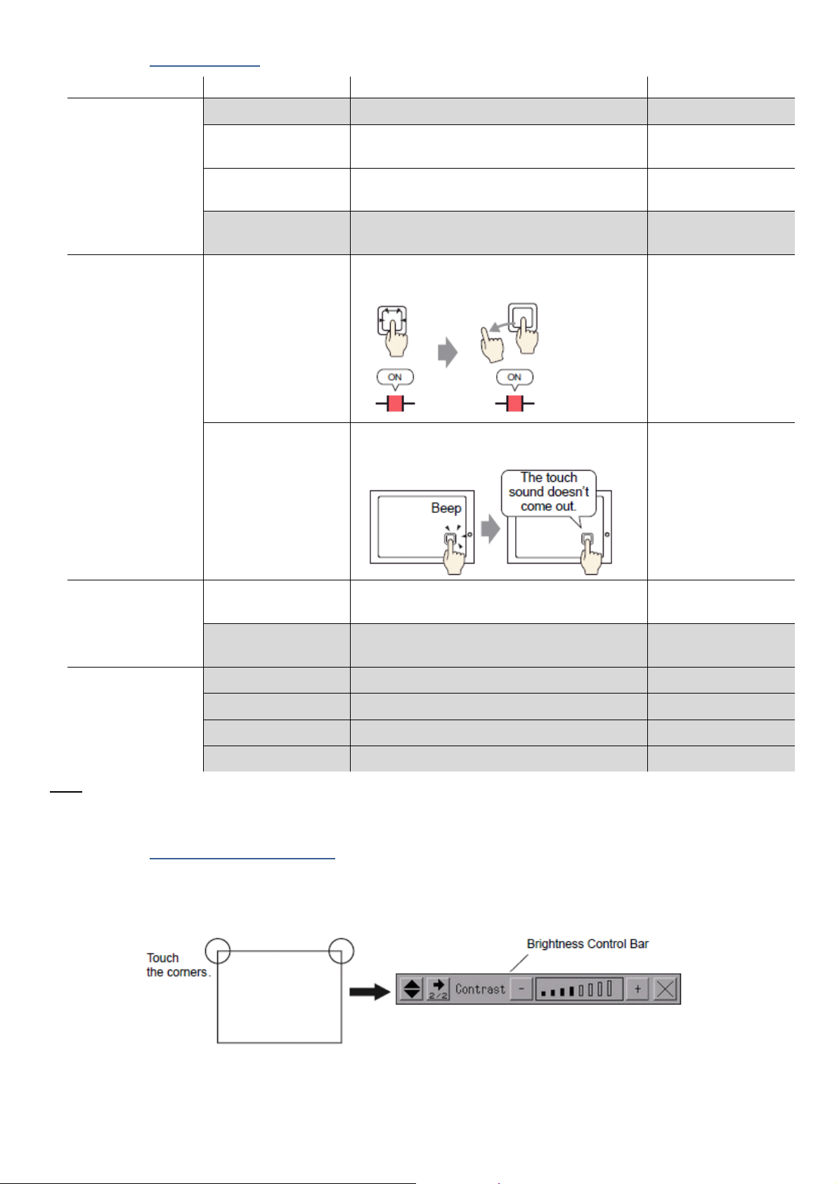
To display the Brightness / Contrast Control Bar on the display unit, enable the setting [Show Brightness/Contrast
Control Bar] in [Display Settings] (§2.2.1)
•
Touch the upper right then left corners, or the Bottom left and right corners of the display in 0.5 seconds.
Specify whether to display on touch the Control
Bar to adjust brightness and contrast.
Enable
Enable
•
To end Brightness/Contrast Control mode, touch the [x] on the Brightness/Contrast Control Bar.
7
User manual SCAIME:
NU-eNodTouch-E-0413
Page 8
2.2.3. Device/PLC Menu
Menu Input Parameter Description Default
Communication SIO Type Set the Communication type RS422/485 (2wire)
Speed Communication Speed : Should be set
Data Length 8
Parity [None]
Stop Bit 2
Flow Control [None]
Time out (s) 2
Retry 1
Wait to send (ms) 10
Device Device Name eNod4
Slave Address eNod4 slave address : Should be set according
Max. Query Read Input
Reg.
Max. Query Read
Holding Reg.
Max. Query Write
Holding Reg.
Driver Info Manufacturer Schneider Electric SA
Series MODBUS SIO Master
N° of Device 1
Note: Never change the parameters in grey
according to eNod4 communication settings
to eNod4 communication settings
30
30
30
9600
1
2.2.4. Password menu
Menu Input Parameter Description Default
System Password System Password The password setting is used when changing
to the Initialize Memory or offline mode
screens.
Security Password Security Password Not used -
Note: Never change the parameters in grey
2.2.5. Initialize menu
Menu Input Action
User memory Deletes all data in the display unit's internal memory.
Enter System password to operate, or 1101 (default password)
Backup Data Clears all the data stored in the display unit's backup memory.
Enter System password to operate, or 1101 (default password)
Note: Never use the commands in grey: You’ll lost the SCAIME eNodtouch application
-
8
User manual SCAIME:
NU-eNodTouch-E-0413
Page 9
2.2.6. Maintenance menu
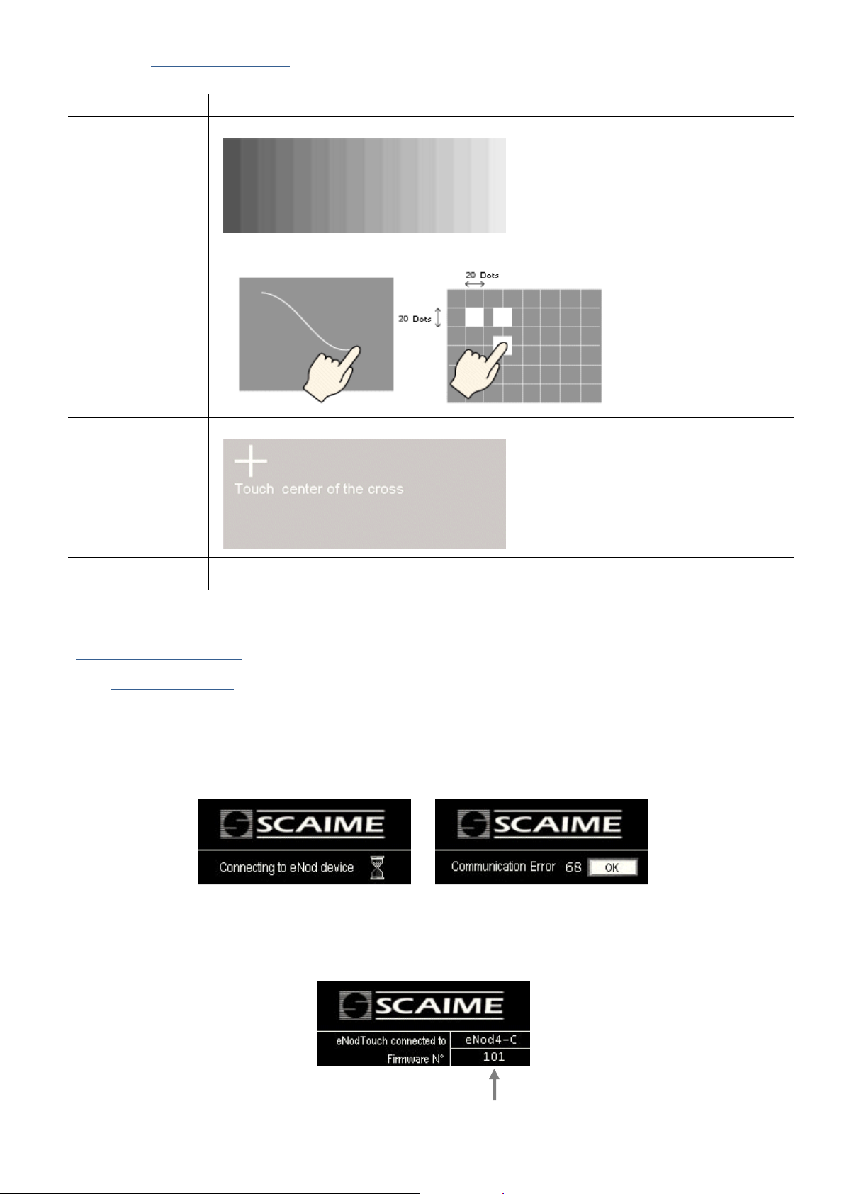
eNod4 model and firmware version
Menu Input Action
Check Pattern Check the drawing function. Confirms whether the liquid crystal display (LCD) displays correctly
Check Touch Panel Touch panel check. Checks that the touched area lights up correctly.
Calibration Correct an analog touch panel. Continue touching until the crosshatch moves or disappears.
Check com Check the send and receive lines of network communication
3. On-Line Functioning
3.1. Startup screens
•
At Power-On, the connection screen is displayed while eNodTouch try to communicate with connected eNod4 device.
•
If the connection screen is displayed more than 5 seconds or if the communication error screen is displayed, consider
the connection cannot be established: check the RS485 wiring (§1.4) and check the eNod4 and eNodTouch
communication settings (§2.2.3).
Connection screen Communication error screen
•
When connection is well established with compatible eNod4 model, the following screen is displayed during 3 seconds.
9
User manual SCAIME:
NU-eNodTouch-E-0413
Page 10
3.2. Main screen
Bar graphe
Gross/Net
indicator
Stability
indicator
Main Keyboard
Keyboard
masked
Status
bar
Inputs / Outputs
Indicators
Gross value
Weight value area
2nd
Keyboard
Checkweigher
Status
bar
Access to Result control screen
Result recorder indicator
Last Checkweigher result
Status
bar
2nd
Keyboard
2nd
Keyboard
Status
bar
Dosing
Status
bar
Access to Res
ult control screen
Dosing cycle status
Last Dosing result
Dosing cycle fault indicator
3.2.1. Transmitter mode (eNod4-T, eNod4-C, eNod4-D)
•
To switch from the Bar graph to the Status bar, touch the Weight value area
•
To switch from the main keyboard to the 2nd keyboard, touch
3.2.2. Checkweigher mode (eNod4-C)
•
To switch from the Bar graph to the Status bar, touch the Weight value area
•
To switch from the main keyboard to the 2nd keyboard, touch
3.2.3. Dosing mode (eNod4-D)
•
To switch from the Bar graph to the Status bar, touch the Weight value area
•
To switch from the main keyboard to the 2nd keyboard, touch
10
User manual SCAIME:
NU-eNodTouch-E-0413
Page 11
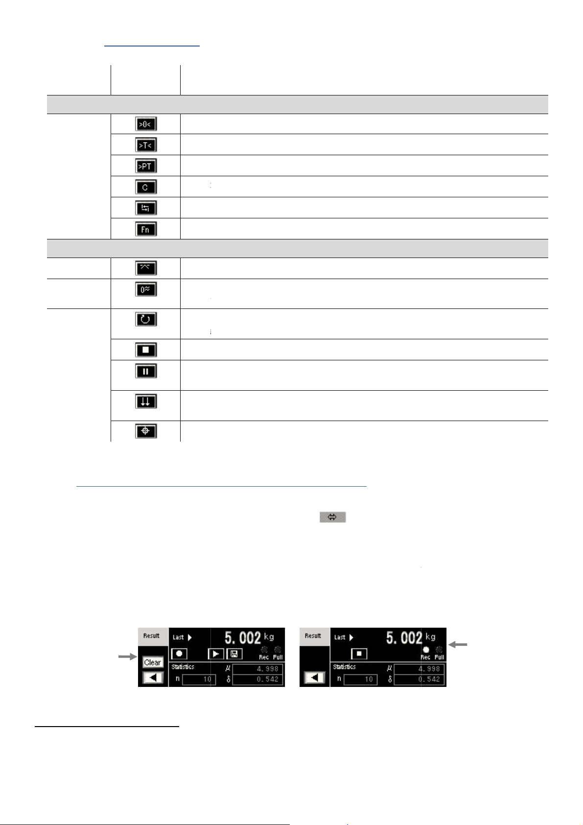
3.2.4. Keyboard functions
Action
ZERO function : possible only under stability condition, according to stability criterion
TARE function : possible only under stability condition, according to stability criterion
PRESET TARE function
CANCEL TARE function
Shift to 2
Enter to Setup menu
Access to thresholds adjustment
DYNAMIC ZERO function : Zero calculation (measurement averaging) without stability
condition
START
dosing cycle is ongoing.
STOP DOSING : Stop the dosing cycle, the dosing
SUSPEND DOSING: Visible only if dosing
suspended dosing cycle without checking starting conditions
MANUAL EMPTYING: Visible only in filling mode with Manual Emptying mode. Allows to
activate the emptying logical output during the emptying
Access to Dosing target adjustment screen
displaying and storage
The Result screen can be displayed from the main screen with
The Result screen shows information related to the result of checkweighing
Last result value and statistics (Number of cycle, Result standard deviation and result average).
From this screen, it is also possible to control a recorder to memorize up to 1000 results with the possibility to
these stored results on USB key in .CSV format.
Recorder stopped Recorder running
, only the main screen and the result
keys giving access to other screens are no longe
menu). To make these buttons visible again, st
Clear
statistics
Start the dosing cycle if starting conditions are satisfied
counter is not incremented
suspension setting is enabled. Allow to restart a
phase
cycle (eNod4
accessible to enable this recording
r visible (eg. Access touch to
Recorder
indicators
eNod4
model
Main Keyboard
Keyboard
touch
All
2nd Keyboard
All
eNod4-C
eNod4-D
nd
keyboard
DOSING:
screen
. Invisible if
3.3. Result
•
•
•
(eNod4-C, eNod4-D)
touch.
-C) or Dosing cycle (eNod4-D):
transfer
control and
Important note about the recorder:
•
When the recorder is running
•
As a consequence, some touch
op the results recorder.
11
User manual SCAIME:
NU-eNodTouch-E-0413
screen are
.
settings
Page 12
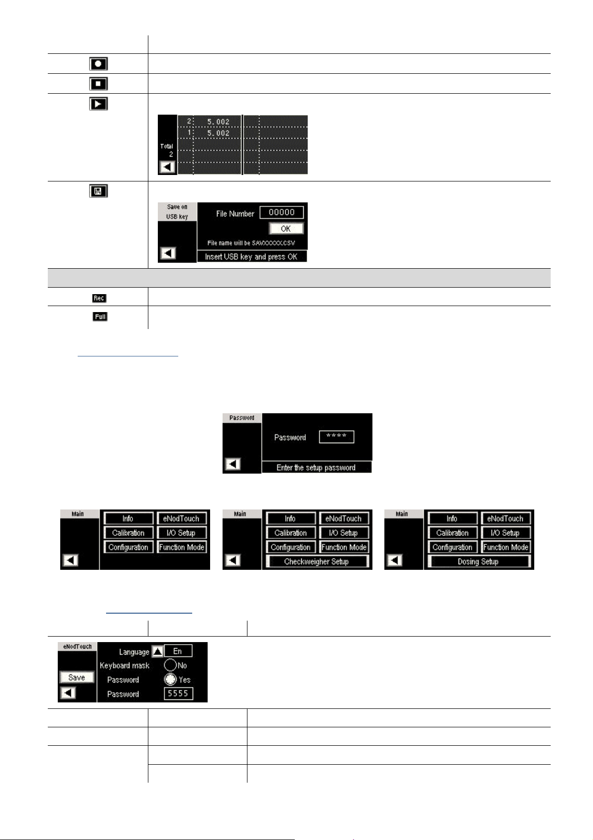
Keyboard touch Action
Indicators
START recorder
STOP recorder
Access to a screen displaying the table of stored results
Access to a screen allowing the Transfer of stored results to an USB key, under .CSV file.
Indicate the recorder running.
Indicate the maximum recorder capacity (1000 results) is reached
3.4. Main setup menu
• eNodTouch setup menu allows to display and modify all the eNod4 parameters. For more information about
parameters, consult eNod4 software manuals.
• Setup menu access can be secured by password (see § 3.4.1). In that case, the following screen is displayed:
• After entering a valid password (or 5555 if you’ve forgot your password), the following menu is displayed:
eNod4-T: Transmitter mode eNod4-C: Checkweigher mode eNod4-D: Dosing mode
3.4.1. eNodTouch setup
Parameter Possible Value Description
Language [Fr], [En] Change the language of eNodTouch software
Keyboard mask [Yes], [No] Enable/Disable keyboard display on main screen
Password [Yes], [No] Enable/Disable access protection to setup menu
4 Char Password value - 5555 (default value) is always valid
12
User manual SCAIME:
NU-eNodTouch-E-0413
Page 13
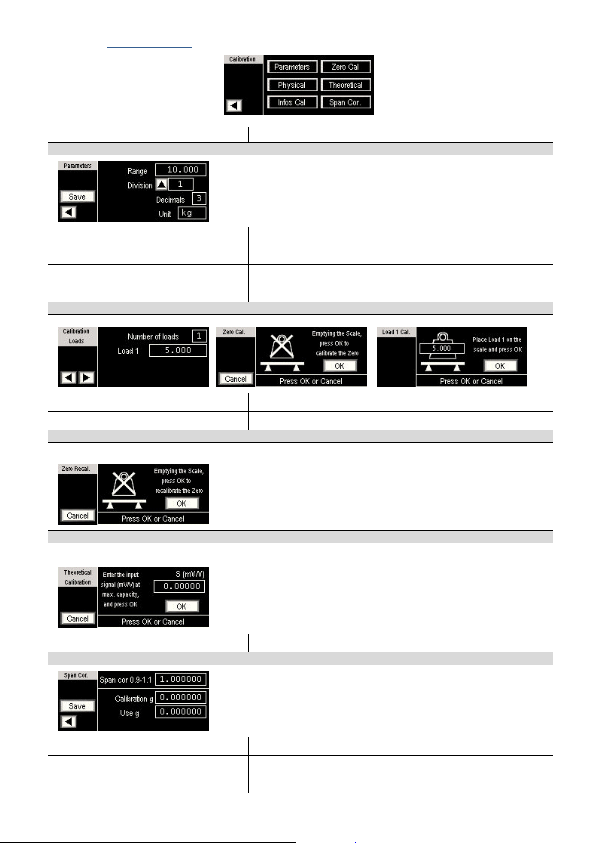
3.4.2. Calibration setup
Parameter Possible Value Description
Calibration Parameters
Range 0 – 1 000 000 Maximum weighing capacity
Division 1, 2, 5, 10, 20, 50 Difference between two consecutive indicated values
Decimals 0-7 Position of decimal point
Unit 4 visible char Weight measurement unit (g, kg, t, lb…) displayed on main screen
Physical calibration
Number of loads 1, 2, 3 Number of calibration loads used during the physical calibration.
load 1/2/3 1 – 1 000 000 Weight values corresponding to each calibration segment.
Zero Calibration
Allows acquiring stable measurement with no load on the scale to set the calibration Zero
Theoretical calibration
An automatic scaling to migrate from the factory calibration to the user calibration.
S (mV/V) 0 – 6.00000 Load cell sensitivity in mV/V at maximum capacity
Span Calibration correction
Span. cor 0.9 – 1.100000 Allows to adjust initial calibration
Calibration g >0 (9.805470) Allows compensating the gravity difference between calibration place
Use g >0 (9.805470)
User manual SCAIME:
and using place.
13
NU-eNodTouch-E-0413
Page 14
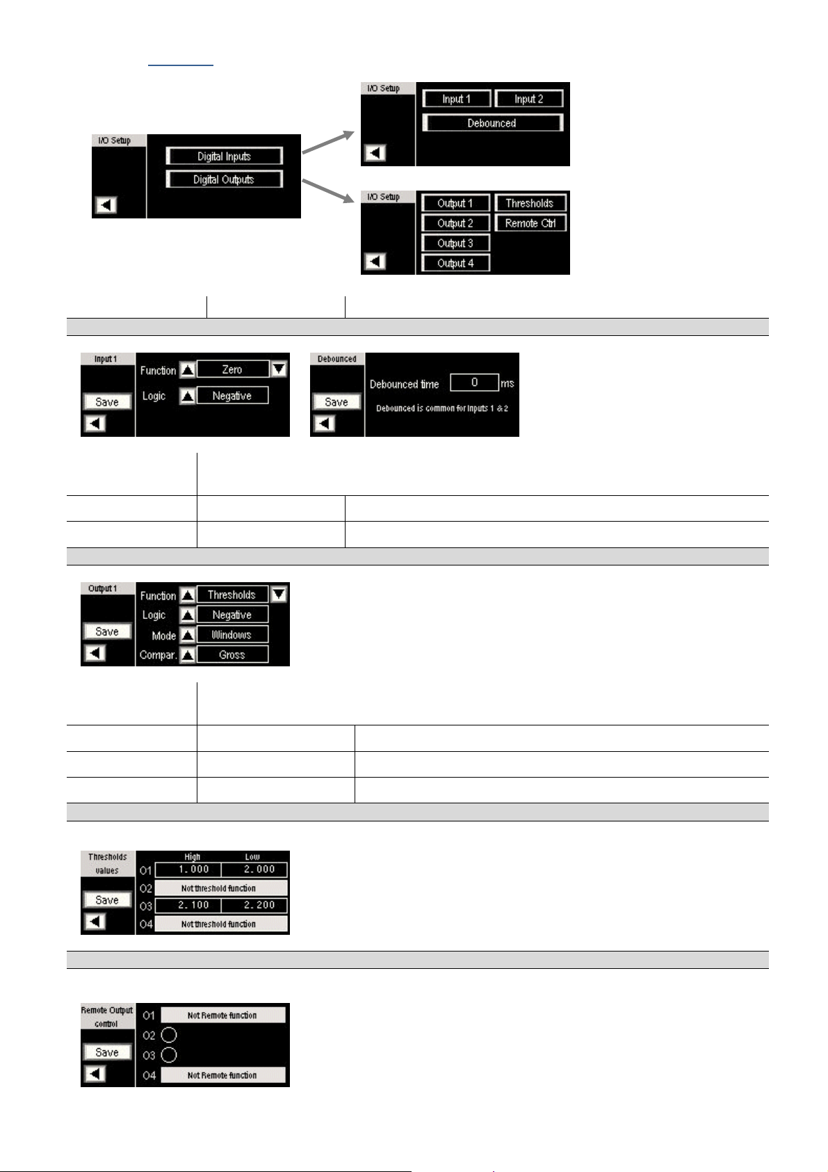
3.4.3. I/O Setup
Parameter Possible Value Description
Input 1-2 Parameters
Function Function assigned to the related input : None, Zero, Tare, Clear, Start cycle, stop cycle, Suspend
cycle, Dynamic Zero, Manual emptying
Logic [Positive]-[Negative] defines the edge (or level) that triggers input function
Debounced time 0 - 65535 Minimum required time of the logical inputs before their activation
Output 1-4 Parameters
Function Function assigned to the related output : None, Thresholds, Stability, Coarse feed, High feed, fine
feed, Cycle ongoing, result available, Out of tolerance, Dosing fault, Input copy, Remote control
Logic [Positive], [Negative] Defines idle output state.
Mode [Windows], [Hysteresis] Thresholds functioning principle
Comparison [Gross], [Net], [result] Comparison value for thresholds control
Thresholds control
Allows modifying the Threshold values of the concerned outputs.
Remote Control
Allows fixing the level [On], [Off], of the concerned outputs.
User manual SCAIME:
14
NU-eNodTouch-E-0413
Page 15
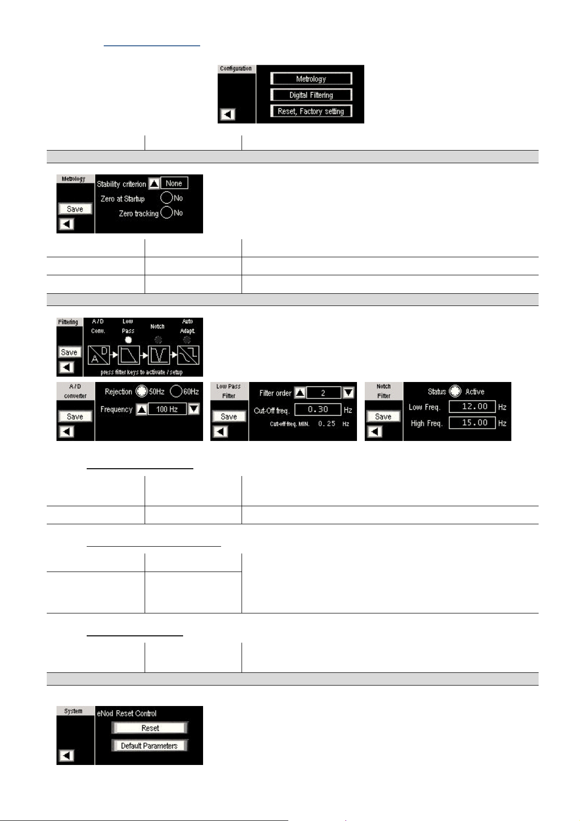
3.4.4. Configuration Setup
Parameter Possible Value Description
Metrology Parameters
Stability criterion None, 0.25 0.5, 1, 2d Defines a stability interval, related to scale interval.
Zero at Startup [Yes], [No] Enable the Automatic Zeroing at power-on
Zero Tracking [Yes], [No] Enable the Zero tracking function
Digital Filtering parameters
A/D converter parameters
Rejection [50Hz]-[60Hz] The A/D converter have In-built adjustable low-pass filter with
frequency rejection of 50 Hz or 60 Hz harmonics.
Frequency 6 – 1600 Hz Filtered measurement frequency is adjustable from 6.25 to 1600 Hz
Bessel low-pass filter parameters
Filter Order 0, 2, 3, 4 For the suppression of periodic vibrations, a Bessel low-pass digital
Cut-Off Frequency 0.1 to 200Hz
Notch Filter parameters
High & Low
Frequency
Reset, factory setting
Allows resetting eNod4 or making eNod4 come back to factory settings
0.1 to 200Hz Frequency band to attenuate with the digital Notch filter
filter can be applied as an output of the A/D converter.
Minimum cut-off frequency value depend on the A/D converter rate:
0.10 Hz for 6.25 meas/s, 4 Hz for 400 meas/s
15
User manual SCAIME:
NU-eNodTouch-E-0413
Page 16
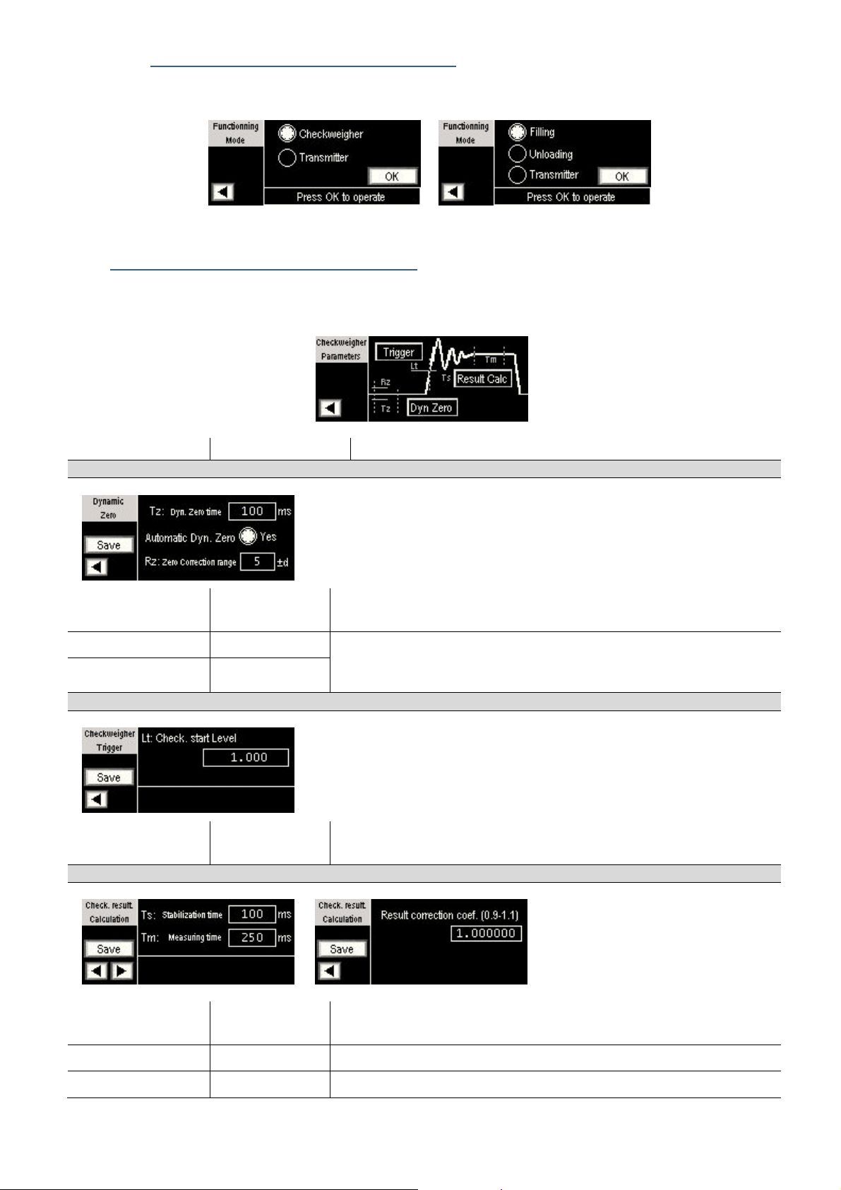
3.4.5. Function mode setup (eNod4-C & eNod4-D)
• According to the eNod4 model, the following screen is displayed to select the functioning mode
eNod4-C eNod4-D
3.5. Checkweigher Setup menu (eNod4-C)
•
Detailed explanations on checkweigher functioning and parameters could be found into eNod4-C manuals
•
The following setup menu allows modifying the parameters related to checkweigher mode.
Parameter Possible Value Description
Dynamic Zero parameters
Dyn. Zero time 0 – 65535 ms The ‘Dynamic zero’ function is the acquisition of a zero without stability
criterion, obtained by averaging measurements during the specified time.
Automatic Dyn. Zero [Yes], [No] Automatic zero correction allows to dynamically track the Zero evolution.
Zero correction range 0 – 255d
Checkweigher Trigger level parameter
Checkweigher start
Level
Result calculation settings
0 – Max. capacity The weight determination cycle can be started by a trigger level, when the
When enabled, an average Zero value is continuously calculated, using the
‘Dyn Zero time’ and ‘Zero Correction range’ parameters.
load cell signal reaches the specified value.
Stabilization time 0 – 65535 ms During this time, measurements are not taken into account for result
calculation
Measuring time 0 – 65535 ms During that time the signal is taken in account to calculate the result.
Result correction 0.9 – 1.100000 Eventually used to adjust the checkweigher result.
16
User manual SCAIME:
NU-eNodTouch-E-0413
Page 17
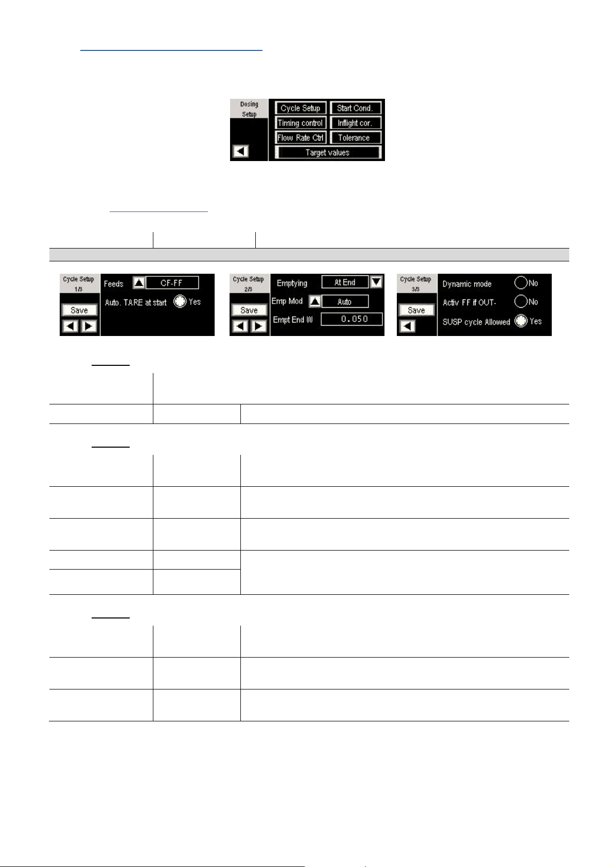
3.6. Dosing Setup menu (eNod4-D)
•
Detailed explanations on Dosing functioning and parameters could be found into eNod4-D manuals
•
The following setup menu allows modifying the parameters related to dosing (Filling or Unloading) mode.
3.6.1. Dosing Cycle Setup
Parameter Possible Value Description
Dosing cycle parameters
Page 1/3
Feeds sequence eNod4-D could manage up to 3 feeds: High Feed (HF), Coarse Feed (CF), Fine Feed (FF). The
number and order of used feeds during a cycle is configured by this parameter.
Auto. TARE at Start [Yes], [No] If enable, TARE function is operated after each dosing cycle start
Page 2/3
Emptying / reloading [No], [At End],
[At Start]
Emptying mode [Auto], [Manual] In filling mode, define the emptying mode: In manual mode, emptying
Emptying end level 0 – 1 000 000 The ‘emptying’ output is disabled if the net value becomes inferior to this
Reloading Min Level 0 – 1 000 000 Output assigned to the reloading function is activated if the gross
Reloading Max Level 0 – 1 000 000
Page 3/3
Dynamic mode [Yes], [No] Selecting this option replaces the stability condition for taking tare /
define the activation / deactivation and position of emptying (Reloading in
unloading mode) option
start after input ‘Manual Emptying’ activation
level and if the ‘emptying holding time’ has elapsed.
measurement is less than reloading Min Level, until the measurement
become greater than reloading max Level.
results by averaging measurements over the ‘Calc time Tare/Result’.
Activ FF if OUT- [Yes], [No] In filling mode, this option automatically restart the Fine Feed if dosing
Suspend/Resume
cycle allowed
result is below low tolerance
[Yes], [No] Allows SUSPEND and RESUME cycle. It makes possible to restart a dosing
cycle when starting weight is greater than "empty max. weight".
17
User manual SCAIME:
NU-eNodTouch-E-0413
Page 18
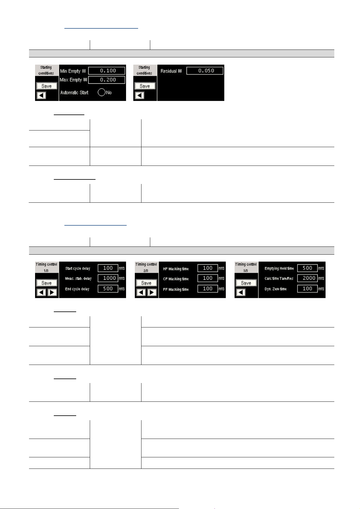
3.6.2. Starting conditions setup
Parameter Possible Value Description
Starting Conditions
Filling mode
Min. empty weight ± 500 000 Allow empty packing presence verification at the start of cycle: Min empty
Max. empty weight
Automatic start [Yes], [No] Filling cycle starts automatically when the gross weight is between the
Unloading mode
Residual weight 0 – 1 000 000 eNod4-D refuse ‘start cycle’ and reports a dosing error if gross
weight < Gross measurement <Max empty weight.
If Min empty weight = Max empty weight = 0: No verification
'Min. empty weight' and 'Max. empty weight'.
measurement <(target weight + residual weight).
3.6.3. Dosing Timing Setup
Parameter Possible Value Description
Timing parameters
Page 1/3
Start cycle delay 0 – 65535 ms
Meas. Stab delay This stabilization time follows the FF stop. After this delay, a new dosing
End of cycle delay This waiting time occurs after Emptying/Reloading. A dosing cycle is
Page 2/3
HF / CF / FF masking
time
0 – 65535 ms During this delay, flow rate and level control are disabled to mask the
This stabilization time precedes the tare execution.
result is calculated by eNod4 –D under stability conditions.
considered complete after this delay.
dynamic effects caused by the related feed activation.
Page 3/3
Emptying / Reloading
Holding time
Calculation time for
Tare / result
Dynamic Zero time time for average calculation used for ‘Dynamic Zero’ command
0 – 65535 ms Defines how long the ‘emptying / Reloading’ output remains active after
the ending of Emptying (or reloading) conditions.
Max. time to search stability for Tare or Result determination. In dynamic
mode, Time to calculate Tare or Result
18
User manual SCAIME:
NU-eNodTouch-E-0413
Page 19
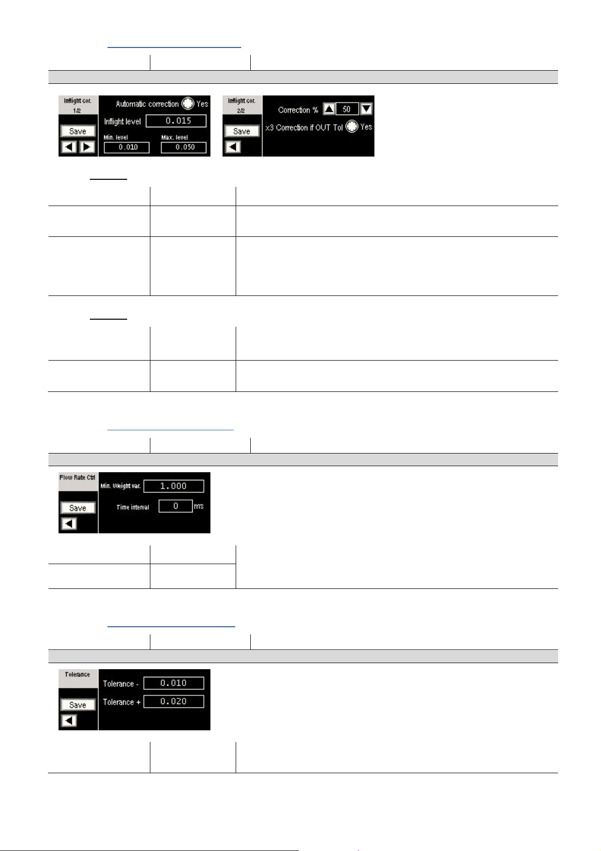
3.6.4. In-flight correction Settings
Parameter Possible Value Description
In-flight correction parameters
Page 1/2
Automatic correction [Yes], [No] If enable, In-flight level is automatically corrected at each end of cycle.
In-Flight weight Level ±500 000 In-flight Level corresponds to the weight of product that carries on falling
after the FF output is disabled. Its value can be automatically corrected.
Min / Max In-Flight
level
Page 2/2
Correction % 0 – 100 % If Automatic correction enabled, the correction formula is:
X3 correction if Out
of Tolerance
±32768 Min In-flight Level < In-flight Level < max In-flight Level. If this condition is
not satisfied, In-flight is not changed.
If these levels are zero, there is no control of limits. But regardless of these
limitations, the value calculated automatically is limited to FF level.
In-flight = In-flight + (Dosing result – Target weight) x Correction %.
[Yes], [No] If the Dosing result is out of Tolerance, ‘Correction %’ is multiplied by 3
(limited at 100 %) inside the correction formula.
3.6.5. Flow rate control settings
Parameter Possible Value Description
Flow rate control parameters
Min. weight variation 0 – 65535 Enable if time interval >0. If during ‘Time interval’, the net measurement
Time Interval 0 – 65535 ms
has been change of less than the ‘minimal weight variation’, then the cycle
is stopped and a flow rate error is detected.
3.6.6. Dosing Tolerance control
Parameter Possible Value Description
Tolerance control parameters
Tolerance – and + 0 – 65565 Define the acceptable range for dosing results. An output assigned to the
‘out of tolerances’ is set active if the dosing result is not within the range.
19
User manual SCAIME:
NU-eNodTouch-E-0413
Page 20
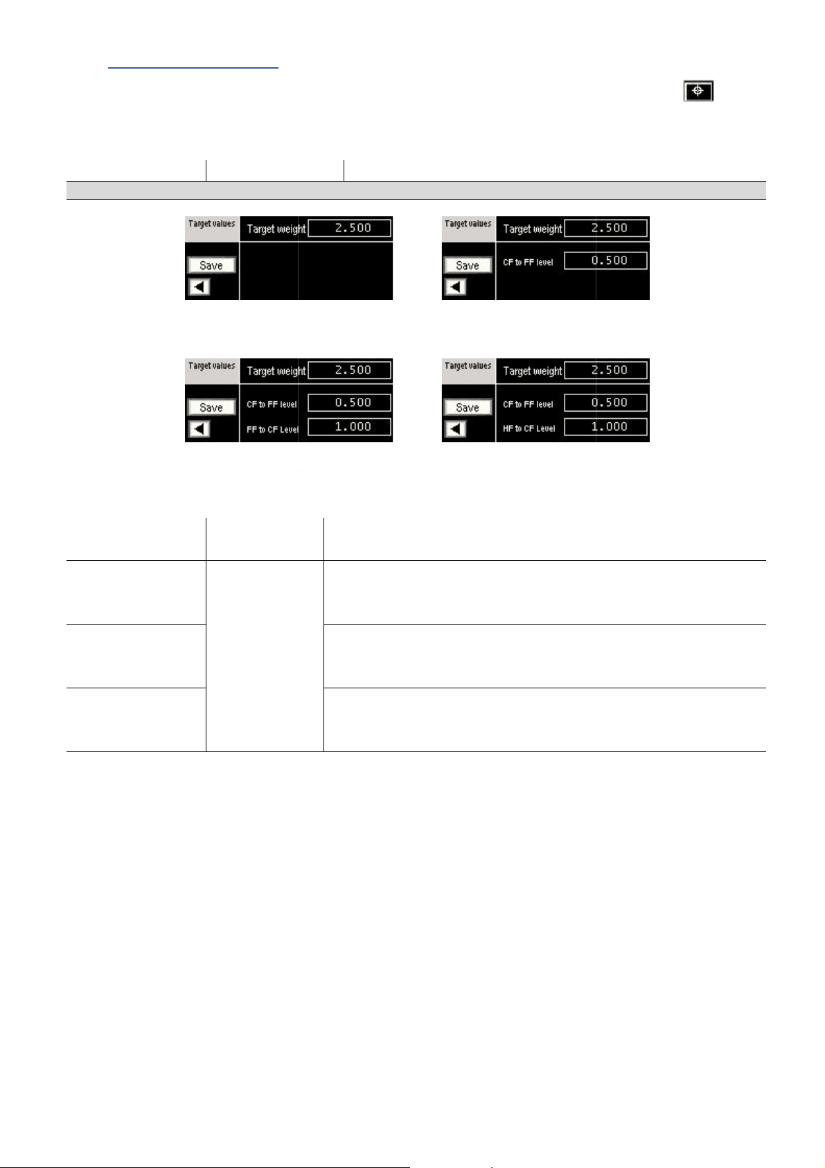
3.7. Dosing Target values
displayed
setting, the following screen are displayed:
CF only
-
+FF)
Setup menu or directly from the main screen with
FF
to reach at the end of the dosing
relative to the target weight
Used in sequences where FF comes before a CF phase.
relative to the target weight
relative to the target weight
•
Target adjustment screen can be
•
According to the Feed sequence
Parameter Possible Value
Target values Adjustment
from the
Description
touch.
FF-CF
FF-(CF
Target weight 0 – 1 000 000
CF to FF Level 0 – 1 000 000
FF to CF Level
CF-FF
(CF+FF)-FF
FF HF-CF-FF
-FF (HF+CF+FF)-(CF+FF)(HF+CF)-CF-FF
Target weight represents the value
process.
Used in sequences using at least 2 or 3 feeds.
Defines the transition threshold,
Coarse feed and Fine Feed phase.
Defines the transition threshold,
Fine Feed and Coarse Feed phase.
, between the
, between the
HF to CF Level
Used in sequences using 3 feeds.
Defines the transition threshold,
High Feed and Coarse Feed phase.
, between the
20
User manual SCAIME:
NU-eNodTouch-E-0413
 Loading...