

Page 1
NU-Soft-eNod4F-E-0716_235704-C.doc
SCAIME SAS – Technosite Altéa – 294, Rue Georges Charpak – 74100 JUVIGNY - FRANCE
Tél. : +33 (0)4 50 87 78 64 – www.scaime.com
eNod4-F
Digital Process Transmitter
Software User Manual
Page 2

2/90
User manual SCAIME: NU-Soft-eNod4F-E-0716_235704-C.doc
1 ENOD4 PRODUCT RANGE ...................................................................................... 7
1.1 General presentation ..................................................................................... 7
1.2 Versions ........................................................................................................... 7
1.2.1 Communication protocol versions ........................................................ 7
1.2.2 IO+ version ............................................................................................... 7
1.3 eNodView Software........................................................................................ 7
2 COMMUNICATION AND FUNCTIONING MODES.................................................. 8
2.1 Communication protocols Modbus RTU and SCMBus ................................ 8
2.2 Functioning mode .......................................................................................... 8
2.3 HMI name ........................................................................................................ 8
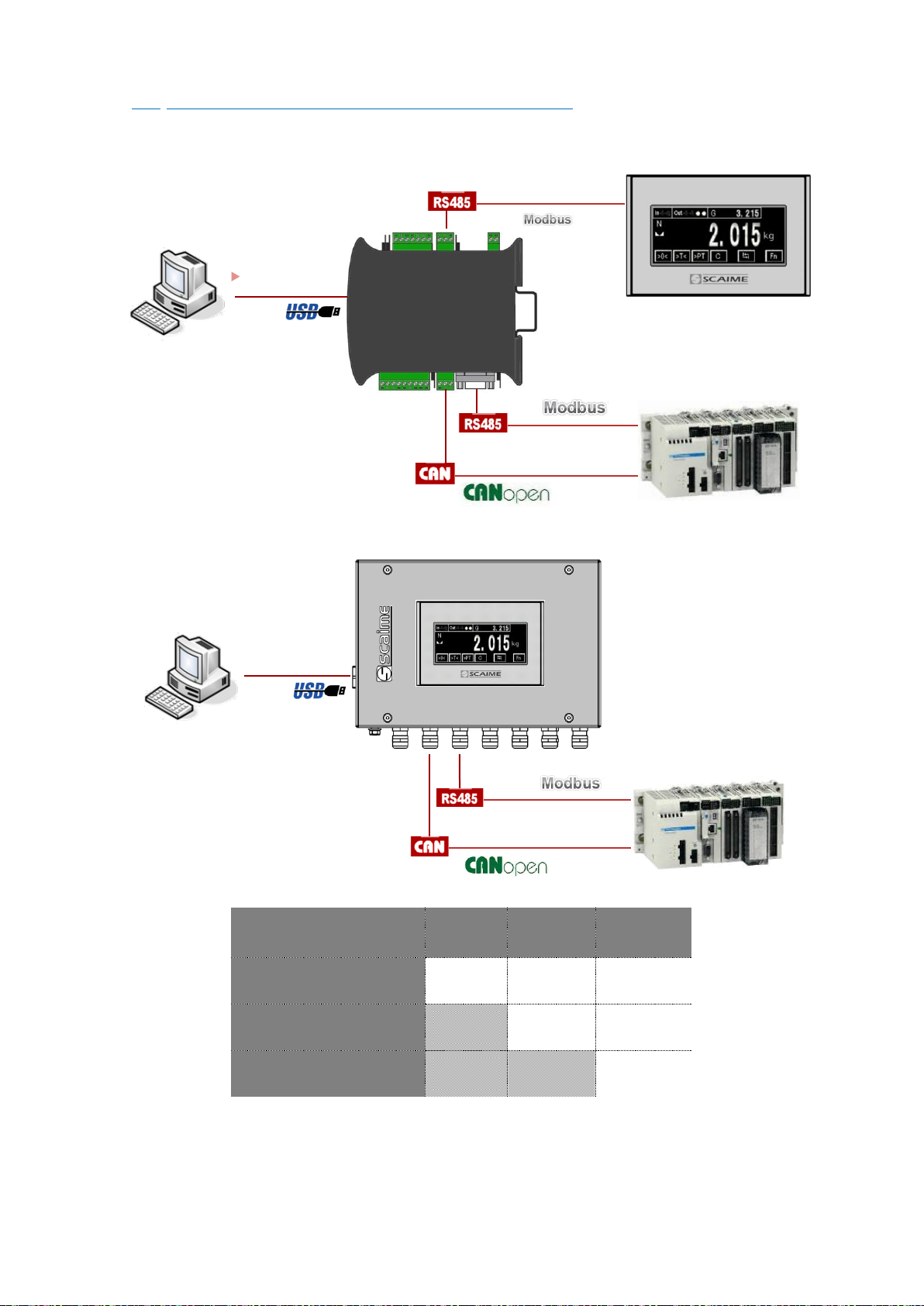
2.4 Simultaneous functioning of communications ............................................ 9
2.4.1 Standard version ..................................................................................... 9
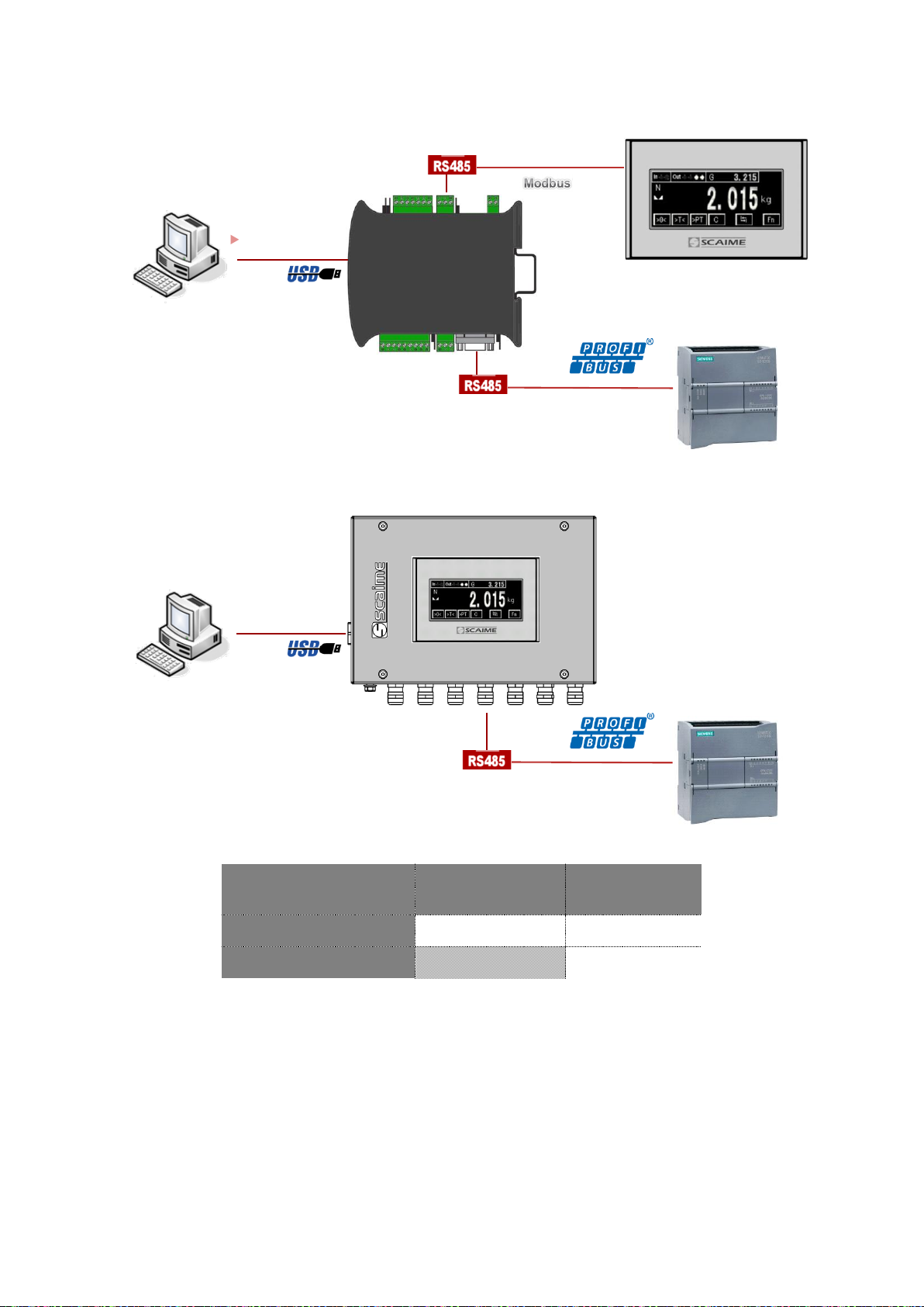
2.4.2 Profibus version ...................................................................................... 10
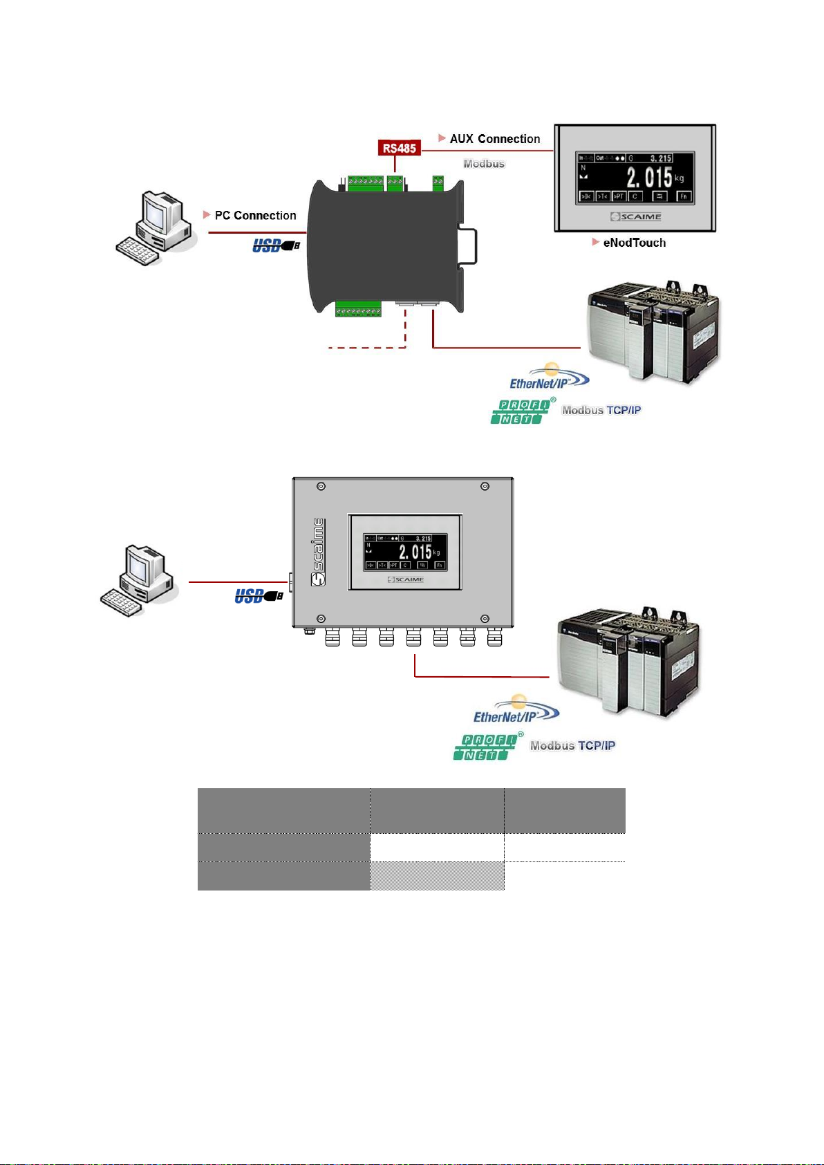
2.4.3 Ethernet versions ................................................................................... 11
3 MODBUS RTU ......................................................................................................... 12
3.1 Physical interfaces ....................................................................................... 12
3.2 Byte format .................................................................................................... 12
3.3 Modbus RTU supported functions ................................................................ 12
3.4 Frames structure ........................................................................................... 12
3.4.1 Function (03H/04H) – read N input registers (N = 30 max) ................ 12
3.4.2 Function (06H) – write single register ................................................... 12
3.4.3 Function (10H) – preset multiple registers (N = 30 max) .................... 13
3.4.4 Error frames ............................................................................................ 13
3.5 Address and Baud rate ................................................................................ 13
3.6 Product identification ................................................................................... 13
3.7 Measurement transmission .......................................................................... 13
3.8 EEPROM error management ........................................................................ 13
4 SCMBUS / FAST SCMBUS ...................................................................................... 14
4.1 Physical interfaces ....................................................................................... 14
4.2 SCMBus and fast SCMBus features ............................................................. 14
4.3 Byte format .................................................................................................... 14
4.4 Frames structure ........................................................................................... 14
4.4.1 Transmission organization .................................................................... 14
4.4.2 Reading request .................................................................................... 15
4.4.3 Functional command request (tare, zero...) ...................................... 15
4.4.4 Error frame.............................................................................................. 15
4.5 Address and Baud rate ................................................................................ 15
4.6 Product identification ................................................................................... 15
4.7 Measurement transmission .......................................................................... 15
4.8 Continuous transmission .............................................................................. 16
4.9 EEPROM error management ........................................................................ 16
5 CANOPEN ............................................................................................................. 17
5.1 Physical interface ......................................................................................... 17
5.2 LED CANopen ............................................................................................... 17
5.3 Frame format ................................................................................................ 17
5.4 Messages transfers hierarchy...................................................................... 18
5.5 eNod4 status remote management ........................................................... 19
5.5.1 NMT commands .................................................................................... 20
Page 3

3/90
User manual SCAIME: NU-Soft-eNod4F-E-0716_235704-C.doc
5.5.2 Synchronization messages ................................................................... 20
5.5.3 Emergency messages .......................................................................... 20
5.6 Error control services .................................................................................... 21
5.6.1 Heartbeat and boot-up ........................................................................ 21
5.6.2 Node guarding ...................................................................................... 21
5.7 Access to the object dictionary ................................................................. 22
5.7.1 SDO communication ............................................................................ 23
5.7.2 PDO communications ........................................................................... 24
5.8 CANopen command and response registers ........................................... 25
5.9 Communication objects .............................................................................. 25
5.9.1 0x1001 / 0x00 : error register ................................................................ 26
5.9.2 0x1003 : Pre-defined error field ............................................................ 26
5.9.3 0x1005 / 0x00 : synchronization messages COB-ID .......................... 26
5.9.4 0x100C / 0x00 : guard time .................................................................. 26
5.9.5 0x100D / 0x00 : life time factor ............................................................ 27
5.9.6 0x1010 : Store parameters .................................................................... 27
5.9.7 0x1014 / 0x00 : Emergency COB-ID .................................................... 27
5.9.8 0x1016 : Heartbeat consumer time ..................................................... 27
5.9.9 0x1017 / 0x00 : Heartbeat producer time ........................................... 27
5.9.10 0x4800 : Safety mode ......................................................................... 27
5.9.11 Error behavior ...................................................................................... 27
5.10 PDO-related communication objects ...................................................... 27
5.10.1 RPDO default mapping ....................................................................... 27
• 0x1600 : RPDO1 mapping parameters ........................................................... 27
• 0x1601 : RPDO2 mapping parameters ........................................................... 27
• 0x1602 : RPDO3 mapping parameters ........................................................... 27
• 0x1603 : RPDO4 mapping parameters ........................................................... 27
• 0x1604 : RPDO5 mapping parameters ........................................................... 27
5.11 Product identification ................................................................................. 27
• 0x1009 : Manufacturer hardware version ...................................................... 27
• 0x100A : Manufacturer software version........................................................ 27
• 0x1018 : Identity object ................................................................................... 27
5.12 Measurement transmission ........................................................................ 27
5.13 EEPROM error management ...................................................................... 27
6 CANOPEN TPDO MAPPING .................................................................................. 31
6.1 Default TPDOs Mapping ............................................................................... 31
• 0x1A00 : TPDO1 mapping ................................................................................ 31
• 0x1A01 : TPDO2 mapping ................................................................................ 31
• 0x1A02 : TPDO3 mapping ................................................................................ 32
7 PROFIBUS DPV1 ..................................................................................................... 33
7.1 Physical interface ......................................................................................... 33
7.2 GSD file .......................................................................................................... 33
7.3 Cyclic exchanges ........................................................................................ 33
7.3.1 Cyclic inputs modules .......................................................................... 33
7.3.2 Cyclic inputs/outputs modules ............................................................ 33
7.4 Acyclic exchanges ...................................................................................... 34
7.5 eNod4 Profibus DP features ......................................................................... 34
7.5.1 Sync ........................................................................................................ 34
7.5.2 Freeze ..................................................................................................... 34
Page 4

4/90
User manual SCAIME: NU-Soft-eNod4F-E-0716_235704-C.doc
7.5.3 Fail-safe .................................................................................................. 34
7.5.4 Profibus DP standard and extended diagnoses ................................. 34
7.6 Product identification ................................................................................... 35
7.7 Measurement transmission .......................................................................... 35
7.8 EEPROM error management ........................................................................ 35
8 PROFIBUS MODULES LIST ...................................................................................... 36
9 MEASUREMENT AND STATUS ................................................................................ 38
9.1 Measurement transmission .......................................................................... 38
9.1.1 Gross measurement .............................................................................. 38
9.1.2 Net measurement ................................................................................. 38
9.1.3 Tare value .............................................................................................. 38
9.1.4 Factory calibrated points ..................................................................... 38
9.1.5 Preset Tare value ................................................................................... 38
9.1.6 Measurement status .............................................................................. 39
9.2 Weighing diagnosis ...................................................................................... 40
9.2.1 Global weighing diagnosis .................................................................. 40
9.2.2 Sensor input control .............................................................................. 41
10 PROCESSING FUNCTIONAL COMMANDS ......................................................... 42
10.1 Principles ..................................................................................................... 42
10.2 Functional commands list.......................................................................... 43
10.3 Functional commands description ........................................................... 44
10.3.1 Reset ..................................................................................................... 44
10.3.2 EEPROM storage .................................................................................. 44
10.3.3 Restore default settings....................................................................... 44
10.3.4 Zero ....................................................................................................... 44
10.3.5 Tare ....................................................................................................... 45
10.3.6 Cancel tare .......................................................................................... 45
10.3.7 Cancel last command........................................................................ 45
10.3.8 Theoretical scaling .............................................................................. 45
10.3.9 Zero adjustment .................................................................................. 45
10.3.10 Start physical calibration .................................................................. 45
10.3.11 Calibration zero acquisition ............................................................. 45
10.3.12 Segment 1 acquisition ...................................................................... 45
10.3.13 Segment 2/3 acquisition .................................................................. 45
10.3.14 Store calibration ................................................................................ 45
10.3.15 Logical outputs 1-4 activation/deactivation .................................. 45
10.3.16 Zero offset adjustment ...................................................................... 46
10.3.17 Dynamic zero acquisition................................................................. 46
10.3.18 Preset tare .......................................................................................... 46
10.3.19 Sensor input reference...................................................................... 46
10.3.20 Sensor input control .......................................................................... 46
10.3.21 Clear totalization & errors counter ................................................... 46
10.3.22 Dosing / batch start / resume .......................................................... 46
10.3.23 Dosing stop / batch cancel ............................................................. 46
10.3.24 Suspend batch .................................................................................. 46
10.3.25 Emptying hopper (cleaning) ............................................................ 47
10.3.26 Refilling start ....................................................................................... 47
10.3.27 Refilling stop ....................................................................................... 47
10.3.28 Learning cycle on next cycle .......................................................... 47
Page 5

5/90
User manual SCAIME: NU-Soft-eNod4F-E-0716_235704-C.doc
10.3.29 Flow rate calibration ......................................................................... 47
10.3.30 Auto Measurement in two or three points for flow rate calibration47
10.3.31 PID parameters auto-adjustment .................................................... 47
10.3.32 Clear grand total ............................................................................... 48
10.3.33 Clear general total ............................................................................ 48
11 CALIBRATION SETTINGS AND PROCEDURES ..................................................... 49
11.1 Principles ..................................................................................................... 49
11.2 Calibration methods .................................................................................. 50
11.3 Settings description .................................................................................... 50
11.3.1 Maximum capacity ............................................................................ 50
11.3.2 Number of calibration segments ....................................................... 50
11.3.3 Calibration loads 1/2/3 ...................................................................... 50
11.3.4 Sensor sensitivity .................................................................................. 50
11.3.5 Scale interval ....................................................................................... 50
11.3.6 Zero calibration ................................................................................... 50
11.3.7 Span coefficients 1/2/3 ...................................................................... 50
11.3.8 Span adjusting coefficient ................................................................. 51
11.3.9 Calibration place g value / place of use g value ........................... 51
11.3.10 Zero offset........................................................................................... 51
12 FILTERS ................................................................................................................. 52
12.1 Principles ..................................................................................................... 52
12.2 Settings description .................................................................................... 53
12.2.1 A/D conversion rate ............................................................................ 53
12.2.2 Filters activation & order ..................................................................... 53
12.2.3 Low-pass filter cut-off frequency ....................................................... 53
12.2.4 Limitations ............................................................................................ 54
12.2.5 Depth of moving average filter on weights ...................................... 54
12.2.6 Tolerance of clipping filter on instant flow rates .............................. 54
12.2.7 Average flow rate determination depth ........................................... 54
13 CONFIGURATION OF INPUT/OUTPUT ................................................................. 55
13.1 Principles ..................................................................................................... 56
13.1.1 Logical inputs....................................................................................... 56
13.1.2 Analog output (IO+ version) .............................................................. 57
13.1.3 Logical outputs .................................................................................... 58
13.2 Settings description .................................................................................... 60
13.2.1 Logical inputs assignment .................................................................. 60
13.2.2 Holding time (debounced time) ........................................................ 62
13.2.3 Analog output(s) assignment (IO+ version) ..................................... 63
13.2.4 External value to control analog output (IO+ version) .................... 63
13.2.5 Logical outputs 1&2 assignment ........................................................ 64
13.2.6 Logical outputs 3&4 assignment ........................................................ 65
13.2.7 Weight quantity per pulse on logical output .................................... 65
13.2.8 Set points functioning ......................................................................... 66
13.2.9 Set points high and low values .......................................................... 67
13.3 Input/output level ....................................................................................... 68
14 LEGAL FOR TRADE OPTIONS ............................................................................... 69
14.1 Principles ..................................................................................................... 69
14.2 Settings description .................................................................................... 69
14.2.1 Legal for trade switch ......................................................................... 69
Page 6

6/90
User manual SCAIME: NU-Soft-eNod4F-E-0716_235704-C.doc
14.2.2 Legal for trade software version ........................................................ 69
14.2.3 Legal for trade counter ....................................................................... 69
14.2.4 Legal for trade checksum .................................................................. 70
14.2.5 Zero functions ...................................................................................... 70
14.2.6 Stability criterion .................................................................................. 70
14.2.7 Decimal point position ........................................................................ 71
14.2.8 Weight unit ........................................................................................... 71
14.2.9 Flow rate time unit ............................................................................... 71
14.2.10 Save Tare and Zero in non-volatile memory .................................. 71
15 LOSS IN WEIGHT FEEDER ..................................................................................... 72
15.1 Settings list ................................................................................................... 72
15.2 Settings description .................................................................................... 75
16 REGISTERS TABLE ................................................................................................. 80
17 CRC-16 CALCULATION ALGORITHM ................................................................. 90
Page 7

7/90
User manual SCAIME: NU-Soft-eNod4F-E-0716_235704-C.doc
1 ENOD4 PRODUCT RANGE
1.1 General presentation
eNod4 is a high speed digital process transmitter with programmable functions and powerful signal
processing capabilities. eNod4 offers operating modes for advanced process control both static and
dynamic.
Quick and accurate:
• Analog to digital conversion rate up to 1920 meas/s with maximum scaled resolution of ±500 000 points.
• Digital filtering and measurement scaling.
• Measurement transmission up to 1 000 meas/s.
Easy to integrate into automated system:
• USB, RS485 and CAN communication interfaces supporting ModBus RTU, CANopen® and PROFIBUS-DPV1
(depending on version) communication protocols.
• Digital Inputs/Outputs for process control.
• Setting of node number by rotary switches and communication baud rate by dip switches.
• Integrated selectable network termination resistors.
• Wiring by plug-in terminal blocs.
1.2 Versions
1.2.1 Communication protocol versions
• Strain gauges load-cell conditioner with CANopen® and ModBus RTU communication.
• Strain gauges load-cell conditioner with Profibus DP-V1 and ModBus RTU communication.
• Strain gauges load-cell conditioner with Modbus TCP and ModBus RTU communication.
• Strain gauges load-cell conditioner with EtherNet/IP and ModBus RTU communication.
• Strain gauges load-cell conditioner with Profinet IO and ModBus RTU communication.
• Strain gauges load-cell conditioner with EtherCAT and ModBus RTU communication.
EDS, GSD, ESI and GSDML configuration files for above protocols can be downloaded from our web site:
http://www.scaime.com
1.2.2 IO+ version
In conjunction with all communication protocol versions, eNod4 can supports an opto-insulated board fitted
with:
• 2 additional digital inputs and 1 speed sensor dedicated input.
• 0-5V or 0-10V analog output voltage.
• 4-20mA, 0-24mA, 0-20mA or 4-20mA with alarm at 3.6mA analog output current.
1.3 eNodView Software
So as to configure eNod4, SCAIME provides eNodView software tool. eNodView is the software dedicated
to eNod devices and digital load cell configuration from a PC. This simple graphical interface allows
accessing the whole functionalities of eNod4 for a complete setting according to the application.
eNodView features and functions:
• eNod4 control from a PC
• Calibration system
• Modification/record of all parameters
• Measure acquisition with graphical display
• Numerical filters simulation
• Frequential analysis FFT
• Process control
• Network parameter
eNodView software is available in English and French version and can be downloaded from our web site:
http://www.scaime.com or ordered to our sales department on a CD-ROM support.
Page 8

8/90
User manual SCAIME: NU-Soft-eNod4F-E-0716_235704-C.doc
2 COMMUNICATION AND FUNCTIONING MODES
Name
Modbus
address
CANopen®
Index/sub-
index
Profibus cyclic
IN/OUT
Acyclic DPV1
slot/index
Type
Access
Functioning mode / Serial
protocol AUX/USB
0x003E
0x2000/0x00
R : 0x02E8
W: 0x02E9
0x07 / 0x39
Uint
RW
Nom IHM
0x0034
0x3701/0x00
/
0x0B / 0x00
String
RW
2.1 Communication protocols Modbus RTU and SCMBus
Modbus RTU, SCMBus, and fast SCMBus communication protocols are accessible through AUX, USB. Modbus RTU or
Profibus only depending on version on DB9 connection.
The protocol can be changed via the « Functioning mode/ serial protocol » register (see below).
bits b9b8
Protocol
00
SCMBus
01
Modbus RTU
11
Fast SCMBus
Note: To be applied, any modification of this setting must be followed by an EEPROM back up and device reboots
(hardware or software).
2.2 Functioning mode
The « Functioning mode/ serial protocol » register offers the possibility to change the eNod4 application according to
the following list:
Note: To be applied, any modification of this setting must be followed by an EEPROM back up and device reboots
(hardware or software).
2.3 HMI name
The “HMI name” is a string of 4 characters freely usable to identify the node on any HMI connected to eNod.
bits
b1b0
Functioning mode
eNod4-T
eNod4-C
eNod4-D
eNod4-F
eNod4-B
00
Transmitter
Transmitter
Transmitter
Transmitter
Transmitter
01
/
Checkweigher
transmitter on request
Dosing by filling
Dosing
Belt scale
10 / /
Dosing by unfilling
/
Belt weigh feeder
Page 9
9/90
User manual SCAIME: NU-Soft-eNod4F-E-0716_235704-C.doc
2.4 Simultaneous functioning of communications
2.4.1 Standard version
• DIN Version
PC Connection
AUX Connection
PLC Connection
eNodTouch
• BOX Version
Simultaneous
Communication
RS485 PLC
RS485 AUX
CAN
USB
Yes*
No
Yes*
RS485 PLC
Yes
No
RS485 AUX
Yes*
(*)Simultaneous use of CAN or RS485 PLC communication with USB or RS485 AUX can reduce performance of this
interface.
PC Connection
PLC Connection
PC Connection
AUX Connection
eNodTouch
Page 10
10/90
User manual SCAIME: NU-Soft-eNod4F-E-0716_235704-C.doc
2.4.2 Profibus version
• DIN Version
PC Connection
AUX Connection
PLC Connection
PROFIBUS-DPV1
eNodTouch
• BOX Version
Simultaneous
Communication
Profibus
RS485 AUX
USB
Yes*
No
Profibus
Yes*
(*)Simultaneous use of Profibus with USB or RS485AUX can reduce performance of this interface.
PC Connection
PLC
Connection
PROFIBUS
-
DPV1
PC Connection
AUX Connection
eNodTouch
Page 11
11/90
User manual SCAIME: NU-Soft-eNod4F-E-0716_235704-C.doc
2.4.3 Ethernet versions
• DIN Version
• BOX Version
Simultaneous
Communication
Ethernet
RS485 AUX
USB
Yes*
No
Ethernet
Yes*
(*)Simultaneous use of Ethernet with USB or RS485 AUX can reduce performance of this interface.
PC Connection
Page 12

12/90
User manual SCAIME: NU-Soft-eNod4F-E-0716_235704-C.doc
3 MODBUS RTU
3.1 Physical interfaces
Modbus RTU communication protocol can be used either through eNod4 USB port, AUX port. Modbus RTU or Profibus
only depending on version on DB9 connection.
USB port behaves as a full duplex interface whereas the DB9 and AUX ports support half-duplex RS485
communication. Supported baud rates are 9600, 19200, 38400, 57600, and 115200.
For a complete description of the recommendations about eNod4 RS485 connection, please refer to the user manual
“characteristics and functioning” of the eNod4.
Note: using eNod4 through USB requires installing first the necessary USB drivers available on the website
http://www.scaime.com.
3.2 Byte format
Data transmitted to eNod4 thanks to Modbus RTU communication protocol must respect following format:
• 1 start bit
• 8 data bits
• no parity
• 2 stop bits
Every Modbus RTU frame is ended by a CRC-16 2-bytes code whose polynomial generator is
(cf. CRC-16 calculation algorithm).
3.3 Modbus RTU supported functions
As a Modbus RTU slave, eNod4 supports following Modbus RTU functions:
Function
Code
read N registers*
03H / 04H
write 1 register*
06H
write N registers*
10H
* 1 register = 2 bytes, maximum admitted value for N is 30.
Note: Broadcast addressing is not allowed by eNod4.
3.4 Frames structure
During a read or write transaction, the two bytes of a register are transmitted MSB first then LSB.
If a data is coded on 4 bytes (that means it requires two registers), the two LSB are stored in the low address register
and the two MSB are stored in the high address register.
3.4.1 Function (03H/04H) – read N input registers (N = 30 max)
• request command sent to the slave :
slave address
03H or 04H
starting register
offset
N registers
CRC16
1 byte
1 byte
2 bytes
2 bytes
2 bytes
• slave response :
slave address
03H or 04H
NB *
data 1
…
CRC16
1 byte
1 byte
1 byte
2 bytes
2 bytes
2 bytes
* NB: number of read bytes (= N*2)
3.4.2 Function (06H) – write single register
• request command sent to the slave :
slave address
06H
register offset
data
CRC16
1 byte
1 byte
2 bytes
2 bytes
2 bytes
G(x) = x16+ x15 + x2 + 1
Page 13
13/90
User manual SCAIME: NU-Soft-eNod4F-E-0716_235704-C.doc
• slave response :
slave address
06H
register offset
data
CRC16
1 byte
1 byte
2 bytes
2 bytes
2 bytes
3.4.3 Function (10H) – preset multiple registers (N = 30 max)
• request command sent to the slave :
slave address
10H
starting register
offset
N registers
NB
Data 1
…
CRC16
1 byte
1 byte
2 bytes
2 bytes
1 byte
2 bytes
2 bytes
2 bytes
• slave response :
slave address
10H
starting register
offset
N registers
CRC16
1 byte
1 byte
2 bytes
2 bytes
2 bytes
3.4.4 Error frames
• frame format in case of a transaction error :
slave address
Function code
+ 80H
error code
CRC16
1 byte
1 byte
1 byte
2 bytes
• Error codes meaning :
Error code
Meaning
description
01H
illegal function
Modbus-RTU function not supported by eNod4
02H
illegal data address
register address requested out of eNod4 register table
03H
illegal data value
forbidden data values for the requested register
04H
eNod4 not ready
eNod4 is not ready to answer (for example measurement
request during a taring operation)
3.5 Address and Baud rate
Address Modbus RTU
Meaning
Access
Type
0x0001
Address and Baud rate
RO
Uint
Reads the address and baud rate selected on the front panel via the rotary switches and dipswitches.
3.6 Product identification
Software and product versions of the eNod4 are accessible via Modbus RTU.
Address Modbus RTU
Meaning
Access
Type
0x0000
SW and product version
RO
Uint
The 12 LSB bits define the software version (073H = 115) and the 4 MSB bits define the product version (6H for the
eNod4).
3.7 Measurement transmission
As a master/slave protocol, measurement transmission in Modbus protocol is only done on master request.
3.8 EEPROM error management
Functioning and calibration parameters are stored in EEPROM. After every reset the entireness of parameters stored
in EEPROM is checked. If a default appears, measurements are set to 0xFFFF and default is pointed out in
measurement status.
Page 14
14/90
User manual SCAIME: NU-Soft-eNod4F-E-0716_235704-C.doc
4 SCMBUS / FAST SCMBUS
4.1 Physical interfaces
SCMBus and fast SCMBus communication protocols can be used either through eNod4 USB port and AUX port.
USB port behaves as a full duplex interface whereas the DB9 and AUX ports support half-duplex RS485
communication. Supported baud rates are 9600, 19200, 38400, 57600, and 115200.
For a complete description of the recommendations about eNod4 RS485 connexion, please refer to the user manual
“characteristics and functioning” of the eNod4.
Note : using eNod4 through USB requires installing first the necessary USB drivers available on the website
http://www.scaime.com.
4.2 SCMBus and fast SCMBus features
SCMBus and its variant fast SCMBus can be imbricate into ModBus RTU protocol if the setting ‘communication
protocol’ is set to SCMBus or fast SCMBus. That means that eNod4 continues answering Modbus RTU frames but it
also allows the device to send frames coded according to SCMBus/fast SCMBus format.
Each protocol has its advantages:
• in SCMBus measurements are transmitted as ASCII with the decimal point and the unit integrated to the
frame
• fast SCMBus is dedicated to fast measurement transmission as the frames are the most compact as
possible
• both protocols allow to communicate without any master request (continuous transmission or sampling
triggered by a logical input)
4.3 Byte format
Data transmitted to eNod4 thanks to SCMBus or fast SCMBus communication protocol must respect following format:
• 1 start bit
• 8 data bits
• no parity
• 2 stop bits
in SCMBus protocol, data is encoded as ASCII numeral characters (30H ..... 39H) and ASCII hexadecimal characters (3AH
..... 3FH).
in fast SCMBus protocol, data is encoded as signed hexadecimal (see frame structure paragraph) below.
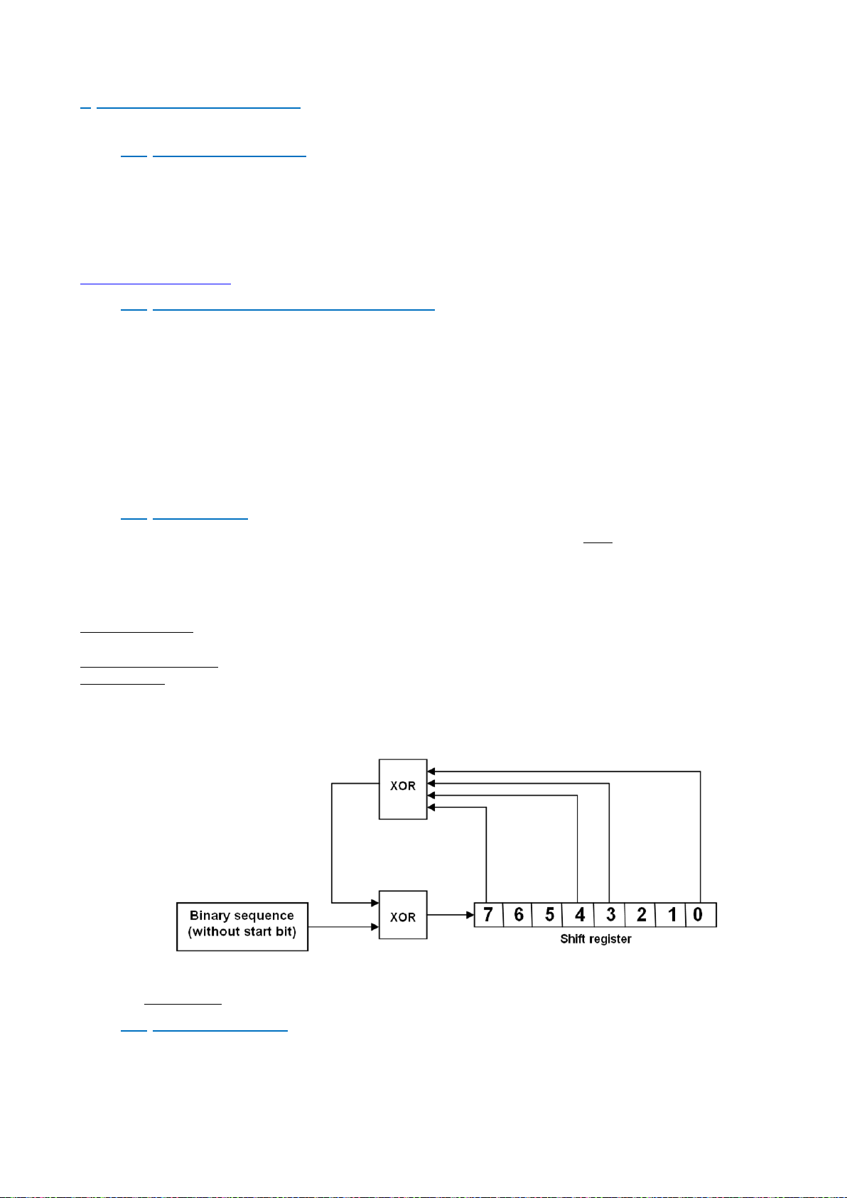
SCMBus CRC-8 byte is generated by the following polynomial:
G(x) = x
8 + x7
+ x4 + x3 + 1
The CRC-8 polynomial result can be determined by programming the algorithm corresponding to the following
diagram:
Note: The frame error detection can be ignored. Value 0xFF of the CRC-8 always is admitted by eNod4 and a received
frame which is ended by such CRC-8 is considered as a frame without any error.
• Fast SCMBus checksum byte is obtained by summing all the frame previous bytes then setting b7 bit to 1.
4.4 Frames structure
4.4.1 Transmission organization
• frame : eNod4 address first
• byte : lsb first
Page 15

15/90
User manual SCAIME: NU-Soft-eNod4F-E-0716_235704-C.doc
• multi-bytes data : MSB first
4.4.2 Reading request
• request
Address
Command
CR
CRC
1 Hex byte
1 Hex byte (command)
1 ASCII byte (0DH)
1 Hex byte
• SCMBus response
Address
Status
Value
CR
CRC
1 Hex byte
2 Hex bytes
N ASCII Hex bytes
1 ASCII byte (0DH)
1 Hex byte
If the ‘decimal point position’ and the ‘unit’ settings are assigned to a non-null value, the response frame when
transmitting measurement contains the decimal point character (2EH) and the unit that is separated from the
measurement value by a space ASCII character (20H).
• Fast SCMBus response
STX
Status word
Value
Cks
ETX
02H
2 Hex bytes
3 signed Hex bytes (2’s
complement)
Σ of previous bytes
and b7 bit set to 1
03H
Note: Because values are encoded in signed hexadecimal bytes format (2’s complement) some data bytes can be
equal to STX (02H) or ETX (03H) or DLE (10H) so before those specific bytes values a DLE (10H) byte is inserted. The
eNod4 address is not transmitted in the frame.
4.4.3 Functional command request (tare, zero...)
• request :
Address
Command
CR
CRC
1 Hex byte
1 Hex byte (command)
1 ASCII byte (0DH)
1 Hex byte
• response (SCMBus and fast SCMBus) :
Address
Command
CR
CRC
1 Hex byte
1 Hex byte (command)
1 ASCII byte (0DH)
1 Hex byte
If the command execution is successful, eNod4 sends back the request frame that has been received as an
acknowledgement.
4.4.4 Error frame
In case of an error upon reception of a request, eNod4 sends back an error frame that contains an error code:
• response (SCMBus and fast SCMBus) :
Address
Error code
CR
CRC
1 Hex byte
1 Hex byte (command)
1 ASCII byte (0DH)
1 Hex byte
• The error codes are listed below:
Error code
Meaning
Description
FEH
unknown command
requested command is not supported by eNod4
FFH
error during command execution
ex. : tare when gross meas.<0
4.5 Address and Baud rate
Address and baud rate identical to Modbus RTU (See § Modbus RTU)
4.6 Product identification
Product identification identical to Modbus RTU (See § Modbus RTU)
4.7 Measurement transmission
Measurement transmission can be triggered by a master request but it might also be triggered and used through the
following options:
• transmission triggered by a rising or falling edge on a logical input
Page 16

16/90
User manual SCAIME: NU-Soft-eNod4F-E-0716_235704-C.doc
• transmission at a configurable period (defined in ms) while a logical input is maintained at a given logical
level
• continuous transmission at a configurable period (defined in ms) after a master request. The transmission
is then stopped by another master instruction, be careful not to use this mode in half-duplex at a too high
rate.
4.8 Continuous transmission
SCMBus and fast SCMBus communication protocols allow eNod4 to transmit measurements at a user-defined rate
without the need for successive master queries. To perform this measurement acquisition mode, it is necessary to set
first the ‘sampling period’ (in ms):
Address SCMBus
Description
Accès
Type
0x003F
SCMBus Measurement
transmission period
RW
Uint
A value of 0 implies that measurement transmission is synchronized on the A/N conversion rate. The continuous
transmission is triggered and stopped by reception of the following commands:
SCMBus/fast SCMBus functional command
Command code
start net measurement transmission
E0H
start factory calibrated points transmission
E1H
start brut measurement transmission
E2H
stop continuous transmission
E3H
Note 1: the measurement transmission rate also depends on the baud rate. So, to achieve the fastest transmission, it
is necessary to use the highest baud rate.
Note 2: as RS485 is a half-duplex communication medium, it can be a little hard to transmit the ‘stop continuous
transmission’ query if the bandwidth is saturated. Therefore, prefer USB communication channel to reach the highest
measurement transmission rate.
4.9 EEPROM error management
EEPROM management identical to Modbus RTU (See § Modbus RTU)
Page 17
17/90
User manual SCAIME: NU-Soft-eNod4F-E-0716_235704-C.doc
5 CANOPEN
5.1 Physical interface
eNod4 is equipped with a CAN 2.0A compatible interface supporting CANopen® communication protocol. The device
can be connected to a CAN bus using CANH and CANL connections. A REF pin can also be connected. Supported baud
rates are 50000, 125000, 250000, 500000 and 1000000.
For a complete description of the recommendations about eNod4 CAN connexion, please refer to documentation
“characteristics and functioning”.
5.2 LED CANopen
The subsequent table describes the meaning of the LEDs for the CAN:
Color
State
Meaning
Red
Single Flash
At least one of the error counters of the CAN controller has reached or
exceed the warning level (too many error frame)
Double Flash
A guard event (NMT-slave or NMT-master) or a heartbeat event
(heartbeat consumer) has occurred
On
The CAN controller is bus off
Flash
Self-test: while the device is performing its power up testing, the LED
shall be flashing red
Green
Blinking
The device is in state PRE OPERATIONAL
Single Flash
The device is in state STOPPED
On
The device is in state OPERATIONAL
5.3 Frame format
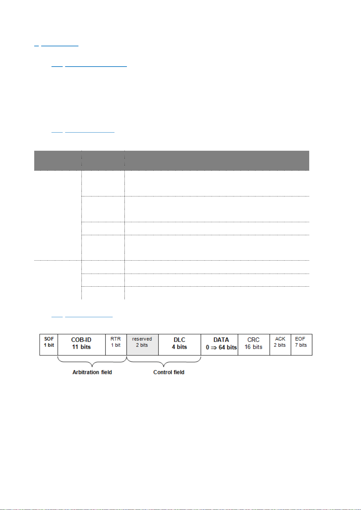
Every data frame sent on the CAN bus has the following structure:
- Start of frame (SOF) : 1 bit
The beginning of a request or a data frame is indicated by the transmission of one
dominant bit.
- Arbitration field : 12 bits
This field contains the message COB-ID on 11 bits and the RTR bit, dominant for data
frames and recessive for remote frames.
- Control field : 6 bits
The first two bits are reserved and must be transmitted as dominant. The four remaining bits encode the
size of the transmitted data in bytes. This is called «Data length code» (DLC) with 0 DLC 8.
Page 18

18/90
User manual SCAIME: NU-Soft-eNod4F-E-0716_235704-C.doc
- Data : de 8 à 64 bits
For each byte, the most significant bit (MSB) is transmitted first.
- Cyclic Redundancy Check (CRC) : 16 bits
The result of the CRC calculation is made up of 15 bits that guarantee the integrity of the
transmitted message. The last bit is used to delimit the field and always is transmitted as
dominant.
- Acknowledgement (ACK) : 2 bits
During two bus clock periods, the bus is available for acknowledgement of the message. All
the nodes that received the message without error generate a dominant bit. Else, an error
frame is generated. The second bit is always recessive.
- End of frame (EOF) : 7 bits
The end of the frame is represented by a sequence of 7 consecutive recessive bits.
The CANopen® layer defines particularly the content of the arbitration and the control fields and the data field
structure.
5.4 Messages transfers hierarchy
CANopen® is a communication protocol especially dedicated to industrial applications. It allows connecting up to 127
different devices on a same bus giving them the possibility to access the bus at any time. Simultaneous emissions are
managed by an arbitration system that uses priority levels.
This control hierarchy of data transfers guarantees that there is no frame collision on the bus while ensuring a high
level of reliability in communications. The low priority messages are cancelled and reissued after a delay.
The protocol defines several message types characterized by their COB-ID (Communication Object Identifier) that
determines the message priority level. The COB-ID is composed of a function code and the node identifier (between 1
and 127).
The node identifier is the device’s address on the network. The function code specifies the priority and the purpose of
the message. Assignment of a particular identifier to each device connected to the bus is mandatory.
eNod4 supports 6 different message types :
CANopen® messages
COB-ID (hex)
NMT
0
SYNC
80
EMCY
81-FF
TPDO1
181 – 1FF
RPDO1
201 – 280
RPDO2
301 – 380
RPDO3
401 – 480
▪ read/write requests : SDO (Service Data Object)
▪ real time transfers : PDO (Process Data Object)
▪ nodes state management : NMT (Network Management)
▪ warnings : EMCY (Emergency)
▪ synchronization events : SYNC (Synchronization)
▪ node status indications : Boot-up/Heartbeat and Node guarding
Page 19
19/90
User manual SCAIME: NU-Soft-eNod4F-E-0716_235704-C.doc
RPDO4
501 – 580
RPDO5(IO+ version)
681 – 6FF
TPDO2
281 – 2FF
TPDO3
381 – 3FF
SDO (Tx)
581 – 5FF
SDO (Rx)
601 – 67F
Heartbeat/Boot-up
701 – 77F
5.5 eNod4 status remote management
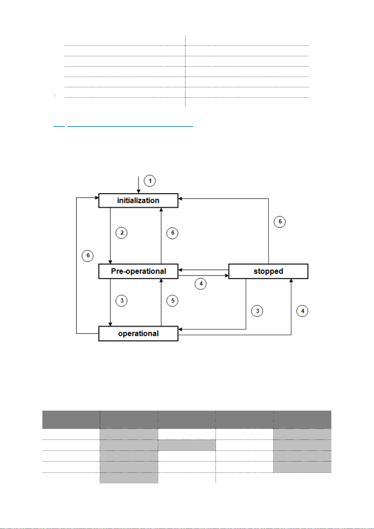
For the CANopen® network, eNod4 is considered as a NMT slave. It means that its state can be modified by a NMT
master present on the bus.
As other CANopen® nodes, eNod4 can be set into one of the four existing states, allowing or forbidding the
reception/emission of CAN messages.
These four states constitute the following NMT state machine:
1 : eNod4 device power-up
2 : automatic transition after the end of initialization
3 : reception of a ‘Start Node’ indication
4 : reception of a ‘Stop Node’ indication
5 : reception of an ‘Enter pre-operational mode’ indication
6 : reception of a ‘Reset node’ or a ‘Reset communications’ indication
eNod4 communication capacities for each state are given in the following table :
Initialization
Pre-operational
Operational
Stopped
SDO XX XX
PDO XX
SYNC XX XX
Emergency
XX XX
NMT XX XX XX
Page 20

20/90
User manual SCAIME: NU-Soft-eNod4F-E-0716_235704-C.doc
Boot-up
XX
Heartbeat
XX XX XX
5.5.1 NMT commands
Except during the initialization phase, eNod4 is able to handle any NMT master’s requests for changing its current
state. All these network management messages are constituted the same way: a two-byte data frame with a COB-ID
equal to zero:
The 2nd byte of the data field contains the node identifier of the device concerned by the request. Its value must be
between 0H and 7FH. The 0H value means that the NMT command concern all the nodes of the network.
The 1st byte codes the command sent to the node. There are five existing commands supported:
« Start node »: 01
H
. eNod4 is set into operational state
« Stop node »: 02
H
. eNod4 is set into stopped state
« Reset node »: 81
H
. Resets eNod4 (with the same effects as a power-up), back into
initialization state.
« Reset communication »: 82
H
. Back into initialization state and communication parameters
reset.
« Enter pre-operational mode »: 80
H
. eNod4 is set into pre-operational state
5.5.2 Synchronization messages
SYNC messages are emitted on the bus by a producer node (generally the NMT master). This service is unconfirmed so
the consumer nodes do not have to respond to SYNC messages. A SYNC message does not carry any data (DLC = 0).
eNod4 is only seen as a SYNC messages consumer whose COB-ID is stored at index 1005H, sub-index 00H of the object
dictionary.
5.5.3 Emergency messages
eNod4 internal errors are reported via emergency frames. Two types of errors can trigger the transmission of an
emergency message:
▪ communication errors
▪ A/D converter input signal range exceeded
Every emergency frame is built as follows:
COB-ID
DLC
byte 0
byte 1
byte 2
byte 3
byte 4
byte 5
byte 6
byte 7
80H
+ ID eNod4
8
emergency code
error register
content
additional information
Emergency message is an unconfirmed service. A frame is emitted when a new error occurs and when it is
acknowledged. The table below describes the emergency standard codes supported by eNod4-T and the translation of
the additional information bytes (in ASCII):
Emergency codes (hex.)
Meaning
0
error acknowledged
3200
voltage error
8120
CAN bus communication error
8130
life guard error
Additional information’s (hex.)
4B4F
no error
474C
life time has elapsed or Heart Beat not received
COB-ID
DLC
byte 1
byte 2 0 2
NMT code
Node identifier
Page 21

21/90
User manual SCAIME: NU-Soft-eNod4F-E-0716_235704-C.doc
564F
sensor signal outside of the input signal range
5054
CAN transmitter in error passive state
5052
CAN receiver in error passive state
The error register value is also part of the emergency telegram so as to indicate if other internal errors have been
detected.
The number of reported errors is given by an error counter in the pre-defined error field located at index 1003H, subindex 00h and the last reported error can be read from the same entry at sub-index 01H.
5.6 Error control services
CANopen® uses smart mechanisms to control permanently the nodes state on the bus. eNod4 supports Boot-up and
Heartbeat messages and Node guarding protocol. Using both services is not allowed. If both are configured so as to
be functional, only the Heartbeat mechanism is used.
5.6.1 Heartbeat and boot-up
eNod4 state control can be achieved through the use of Heartbeat and boot-up mechanisms :
Boot-up: this message sent by eNod4 means that its initialization phase is complete and that the
node has entered into pre-operational state. It consists in the following frame :
Heartbeat :
- producer mode : if a Heartbeat period (in ms) different from 0 is set in the entry ‘producer
heartbeat time’ of the object dictionary, eNod4 generates at this period a frame containing its state
coded on one byte. The corresponding frame is similar to the Boot-up mechanism frame:
eNod4 NMT state byte can take the different following values :
04
H
: the node is in the «stopped» state
05
H
: the node is in the «operational» state
7F
H
: the node is in the «pre-operational» state
Using Heartbeat protocol allows a NMT master to check that all nodes connected to the bus are working correctly.
- Consumer mode: eNod4 also can be configured so as to monitor the NMT state of one particular
node of the network (generally the NMT master). The node ID and a period are defined in the entry
‘consumer heartbeat time’ of the object dictionary
If corresponding heartbeat is not received within this time, then eNod4 sends an emergency
telegram and switches to pre-operational state.
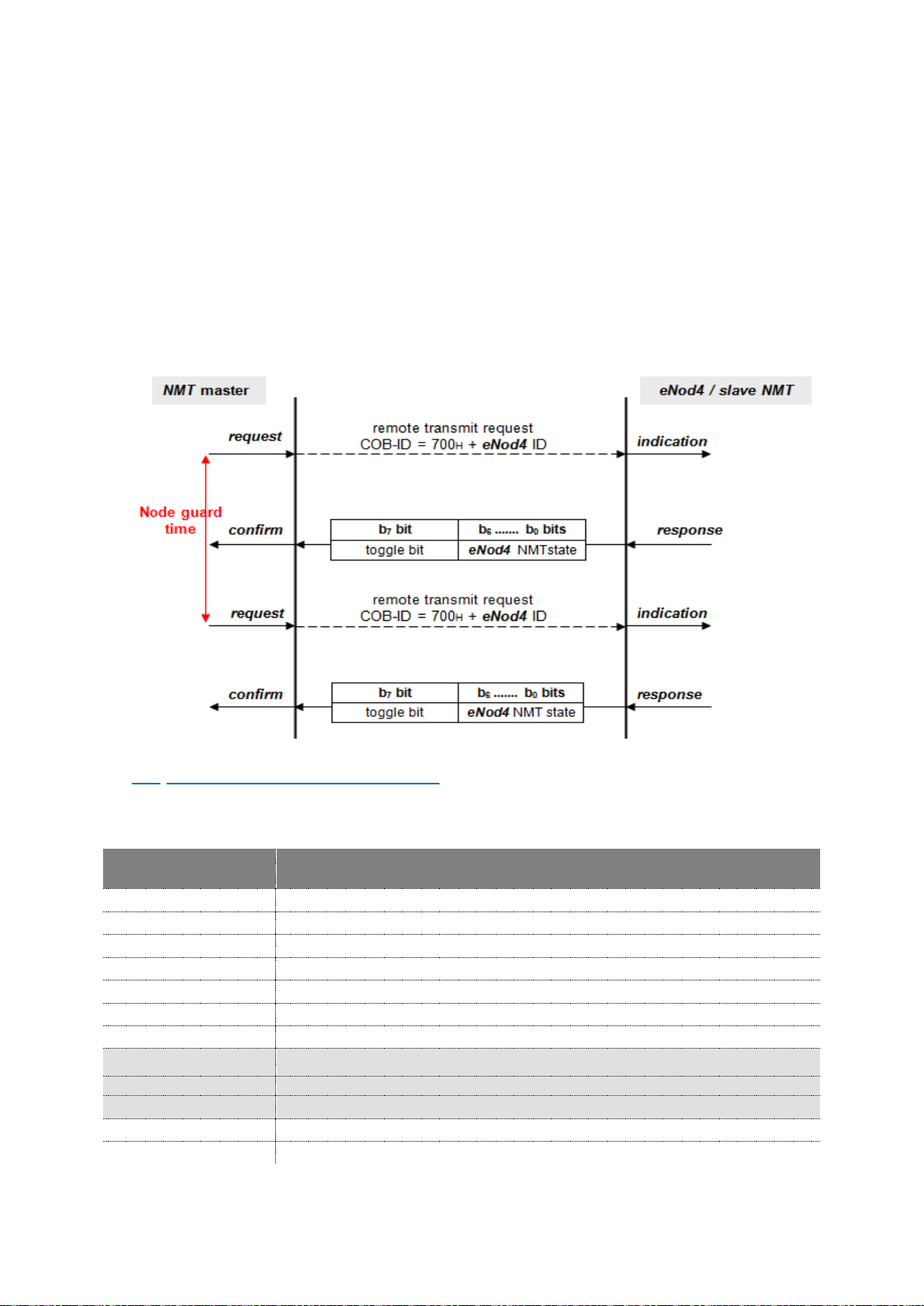
5.6.2 Node guarding
Node guarding protocol is another way to check the nodes state. But unlike Heartbeat protocol, it needs requests
from a NMT master. In this case, the NMT master sends periodically a remote transmit request (remote frame) to the
node with COB-ID 700H + ID eNod4. eNod4 has to respond by sending a single-byte data frame with its coded state.
This frame is similar to Heartbeat frame but there is an important difference. Most significant bit of the state byte is a
toggle-bit. The value of this bit must alternate between two consecutive responses from the NMT slave. The value of
the toggle-bit of the first response after the Guarding Protocol becomes active is 0.
It is only reset to 0 when a ‘reset communications’ or a ‘reset node’ command is received. If two consecutive
responses have the same value of the toggle-bit, then the new response should be handled as if it was not received by
the NMT master.
COB-ID
DLC
byte 1
700H + ID eNod4
1
0
COB-ID
DLC
byte 1
700H + ID eNod4
1
eNod4 NMT state
Page 22
22/90
User manual SCAIME: NU-Soft-eNod4F-E-0716_235704-C.doc
Two parameters of the object dictionary are necessary to set and define node guarding protocol: the ‘guard time’ and
the ‘life time factor’:
Guard time: this parameter expressed in milliseconds indicates the period with which the node is
being polled by the NMT master. This value can be different from one node to another.
Life time factor: when node guarding protocol is active, node life time is given by multiplication of the
guard time and the life time factor.
Node guarding activation is effective when guard time has been set (and if Heartbeat protocol is not used) and after
reception of the first remote transmit request. If life time factor is also configured and if no remote transmit request is
handled within the node life time, eNod4 sends an emergency telegram then switches to pre-operational state. The
life guarding error is acknowledged when the state is changed by a NMT command and after reception of a new
remote transmit request.
Switching to the stopped NMT state because of a node guarding error may cause eNod4 to be set into a configurable
safety mode where parts of its functioning are inhibited
5.7 Access to the object dictionary
The most important element of a CANopen® compatible device is its object dictionary (OD). Each node object that can
be accessed via the bus is part of a table called object dictionary. The dictionary entries can be addressed by a couple
of an index (2 bytes) and a sub-index (1 byte) with the following organization:
Index (hex.)
Object type
0000
reserved
0001 001F
static data types
0020 003F
complex data types
0040 005F
manufacturer specific complex data bytes
0060 007F
device profile specific static data types
0080 009F
device profile specific complex data types
00A0 0FFF
reserved
1000 1FFF
communication profile area
2000 5FFF
manufacturer specific profile area
5FFF 9FFF
standardized device profile area
A000 FFFF
reserved
Only the greyed elements of the table are accessible through eNod4 OD.
Page 23
23/90
User manual SCAIME: NU-Soft-eNod4F-E-0716_235704-C.doc
The whole object dictionary is accessible and can be configured from usual CANopen® configuration tools. This can be
done using eNod4 available EDS file.
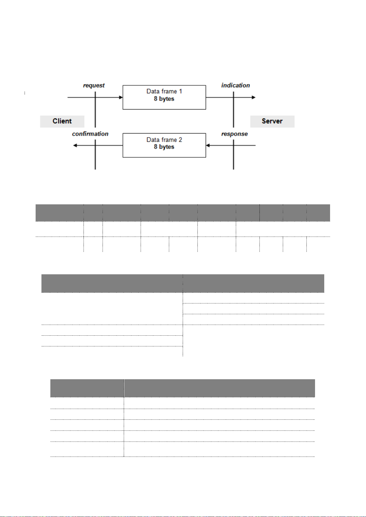
5.7.1 SDO communication
The model for SDO communication is a client/server model as described below:
The node that sends the request is the client application whereas eNod4 only behaves as the server application. There
are two types of requests, write and read requests. Both have the same structure:
COB-ID
DLC
byte 0
byte 1
byte 2
byte 3
byte 4
byte 5
byte 6
byte 7
11 bits
1
byte
Command
byte
Index
sub-index
Data
580H or 600H
+ ID eNod4
8
see table
LSB
MSB
/
LSB - -
MSB
The client request uses the SDO(Rx) COB-ID (600H + ID eNod4 and the server uses the SDO(Tx) COB-ID (580H + ID
eNod4).
The command byte depends on the requested data length:
Client request
Server response
read data 40H
43H 4-bytes data
4BH 2-bytes data
4FH 1-byte data
write 4-bytes data 23H
60H
write 2-bytes data 2BH
write 1-byte data 2FH
For a read request, the value of the four last bytes of the frame (data) does not matter.
If an error occurs during a SDO communication eNod4 responds with the command byte 80H and the four data bytes
contain one of the following SDO abort codes. The data transfer is aborted.
SDO abort codes (hex.)
Description
5040001
SDO command specifier not supported
6010001
unsupported access to an object
6010002
attempt to write a read-only object
6020000
the object does not exist in the object dictionary
6040042
the number and length of the objects to be mapped would exceed PDO
length
6040047
impossible operation (for example reading a net/gross value during a tare
or a zero)
Page 24

24/90
User manual SCAIME: NU-Soft-eNod4F-E-0716_235704-C.doc
6070012
data type does not match, length of service parameter too high
6070013
data type does not match, length of service parameter too low
6090011
Sub index object does not exist.
6090030
value range of parameter exceeded
6090031
value of parameter written too high
6090032
value of parameter written too low
8000020
data cannot be stored to the application
8000022
data cannot be transferred or store to the application because of the
present device state
5.7.2 PDO communications
SDO protocol is not the only way to access the object dictionary. PDO allow to transfer data without including their
index and sub-index in the frame. Both are stored in an OD specific field called PDO mapping.
The model used for PDO transmissions also is different. It is a Producer/Consumer model in which data are sent by a
producer node (TPDO) to a consumer node (RPDO) without any confirmation.
Each PDO is described by a combination of two parameters of the OD: the PDO communication parameters and the
PDO mapping. The PDO communication parameters describe the functioning of the PDO and the PDO mapping
describes its content. eNod4 uses 3 TPDO (2 are programmable) and 5 RPDO.
The PDO transmission mode can be set in the corresponding object with the following attributes:
Synchronous: PDO transmission/reception is triggered by the reception of one or more SYNC messages.
Several options are available :
- cyclic: PDO is sent/received after reception of n (1 n 240) SYNC messages.
- acyclic: PDO is sent at reception of the first SYNC message following a specific device event
(activation of a logical input assigned to ‘send TPDO’ or data variation superior to +/- delta)
- on remote transmit request : PDO is sent after the first SYNC message following a remote
transmit request frame with the PDO COB-ID.
Asynchronous: PDO transmission/reception does not depend on the SYNC messages on the CAN bus.
Several options are available :
- on remote transmit request : PDO is sent at reception of a remote transmit request frame with
the PDO COB-ID.
- activation of a logical input assigned to ‘send TPDO’ or data variation superior to +/- delta)
- on a timer event : PDO is sent periodically (with an adjustable period).
The following table recaps the trigger modes that can be chosen by entering the hexadecimal code in the PDO
communication parameter:
Page 25

25/90
User manual SCAIME: NU-Soft-eNod4F-E-0716_235704-C.doc
Note 1: for RPDO1-2-3-4-5 and TPDO1, only the transmission types FF
H
and 00H are supported. That means
data are updated either immediately upon reception (FFH) or after next SYNC following the RPDO reception
(00H). For TPDO1, the FEH transmission type means that the TPDO1 is emitted by eNod4 every time it’s
mapped value changes. The 00H transmission type is similar but the emission is triggered by the reception of
a SYNC object.
Note 2: RPDO1-2-3-4-5 and TPDO1 mapping are configured with default values that cannot be modified.
5.8 CANopen command and response registers
In CANopen® communication protocol, the ‘command register’ is mapped into RPDO1 and the ‘response register’ is
mapped into TPDO1. When in operational NMT state, eNod4 is able to handle the functional commands received
through RPDO1 and the ‘response register’ value changes are automatically transmitted through TPDO1.
5.9 Communication objects
Some settings are specific as defined by the CANopen® communication specification.
Code
(hex)
cyclic
acyclic
(event)
synchronous
asynchronous
remote
transmit
request
Effect
00
XX XX
XX
PDO transmission/reception after a
SYNC message following one of these
events :
- activation of a logical input assigned
to ‘send TPDO’
- mapped object variation superior to
+/- delta
- Receipt of remote transmit request.
01 – F0
( = n)
XX XX
XX
PDO transmission after n SYNC
messages
- Or after receipt of remote transmit
request following at less one SYNC.
F1 - FB
reserved
FC XX XX
data update at reception of a remote
transmit request and PDO
transmission after reception of a
SYNC message
FD XX XX
data update and PDO transmission
at reception of a remote transmit
request
FE XX XX
PDO transmission is triggered by one
of these events :
- activation of a logical input assigned
to ‘send TPDO’
- mapped object variation superior to
+/- delta
- receipt of remote transmit request
more for TPDO2 and 3, functioning is
identical to code FF
FF XX XX
Periodic TPDO emission. Period can
be configured (min = 1 ms).
RPDO handled upon reception
TPDO emission after receipt of
remote transmit request
Page 26

26/90
User manual SCAIME: NU-Soft-eNod4F-E-0716_235704-C.doc
5.9.1 0x1001 / 0x00 : error register
• access : RO
• data type : unsigned8
• default value : 0
• mappable ? : N
• admitted values : see table below
Description: The device internal errors are indicated by flag bits of this byte. b0 bit (generic error) is set to 1 if at least
one error is detected.
Bit se to 1
Meaning
b0
generic error detected
b1
reserved (0)
b2
A/D converter input voltage error
b3
reserved (0)
b4
CAN bus communication error
b5
reserved (0)
b6
reserved (0)
b7
EEPROM error
5.9.2 0x1003 : Pre-defined error field
Sub-index
Description
Access
Default value
Mappable
(PDO) ?
Type
0x00
reported errors
counter
R/W 0 N
unsigned8
0x01
last reported error
RO 0 N
unsigned32
Description: This entry of the object dictionary stores the errors that have been reported by emergency telegrams.
The reported errors counter (sub-index 00H) is accessible through write or read request but 0 is the only allowed value
for writing transactions. By writing a zero to this sub-index, the error counter is reset and the last reported error (sub
index 01H) is erased. An attempt to write another value is ignored and eNod4 answers the SDO abort code
0x06090030.
5.9.3 0x1005 / 0x00 : synchronization messages COB-ID
• access : R/W
• data type : unsigned32
• default value : 0x80
• mappable ? : N
• admitted values : 0x80 or from 0x7E0 up to to 0x7E3
Description: This object contains the message COB-ID value supported by eNod4 as synchronization messages (used
for PDO activating).
5.9.4 0x100C / 0x00 : guard time
• access : R/W
• data type : unsigned16
• default value : 0
• mappable ? : N
• admitted values : from 0 up to 65535
Page 27

27/90
User manual SCAIME: NU-Soft-eNod4F-E-0716_235704-C.doc
Description: The ‘life guard’ is one of the two parameters used by the node guarding protocol (errors detection).
When ‘Heartbeat time’ is inactive and ‘life guard’ is different from 0, eNod4 responds to NMT master periodic (period
equal to life guard) remote transmit requests.
5.9.5 0x100D / 0x00 : life time factor
• access : R/W
• data type : unsigned8
• default value : 0
• mappable ? : N
• admitted values : from 0 up to 255
Description: By multiplying the ‘life guard’ by the ‘life time factor’, the node life time (cf. §4) can be determined.
When node guarding is active, if the node has not be polled within this duration (in ms), eNod4 state is set to stopped.
eNod4 behavior while stopped can be configured via the object at index 0x4800.
5.9.6 0x1010 : Store parameters
Sub-index
Description
Access
Default value
Mappable
(PDO) ?
Type
0x00
largest sub-
index
RO
0x01
N
unsigned8
0x01
save all
parameters
R/W
0x01
N
unsigned32
In CANoppen® communication protocol, storing all settings into eNod4 EEPROM memory requires writing through
SDO the ASCII string « save » (65766173H) to sub-index 0x01 of entry 0x1010 of the object dictionary (called ‘save all
parameters’ in the EDS file).
• 0x65 e
• 0x76 v
• 0x61 a
• 0x73 s
When accessing to sub-index 1 with a SDO read request, eNod4 cell responds with a value of 1 that means that
parameters are stored in non-volatile memory only on request.
Note: Restore to default settings functional command is not available in CANopen® communication protocol.
5.9.7 0x1014 / 0x00 : Emergency COB-ID
• access : RO
• data type : unsigned32
• default value : 0x81
• mappable ? : N
• admitted values : from 0x81 up to 0xFF
Description: The COB-ID of emergency messages transmitted by eNod4 is stored at this index. Its value automatically
is updated if the node identifier is modified.
5.9.8 0x1016 : Heartbeat consumer time
Sub-index
Description
Access
Default value
Mappable
(PDO) ?
Type
0x00
max. sub-index
RO 1 N
unsigned8
0x01
heartbeat consumer
time
RW 0 N
unsigned32
Description: eNod4 is able to monitor the Heartbeat generated by another node (see §4) of the network (in general
the master). Two settings must be defined through the object at sub-index 0x01:
the heartbeat time period, coded on the 16 LSB bits
the node ID of the heartbeat producer to monitor, coded on the 16 MSB bits (from 0x01 up to
0x7F)
Page 28

28/90
User manual SCAIME: NU-Soft-eNod4F-E-0716_235704-C.doc
5.9.9 0x1017 / 0x00 : Heartbeat producer time
• access : R/W
• data type : unsigned16
• default value : 0
• mappable ? : N
• admitted values : from 0 up to 65535
Description: If a period different from 0 is written into this index, eNod4 periodically generates a Heartbeat frame. It is
expressed in ms and must be comprised between 1 and 65535.
5.9.10 0x4800 : Safety mode
• access : R/W
• data type : unsigned8
• default value : 0H
• admitted values : see table below
Description: This entry defines eNod4 functioning when in stopped NMT state. The safety mode is used when the bit
b0 of the byte is set to 1. The functioning mode is then inhibited and outputs logical level are given by b1, b2, b3 and
b4 bits. The eNod4 leaves the safety mode upon reception of a new NMT command.
Warning: In safety mode, when the eNod4 is in stopped NMT state, functioning is also
inhibited using Modbus and SCMBus communication. For example, it is not possible to tare or make a zero using RS
485 AUX port, or eNodView connected via USB.
b0
Effect
Notes
0
safety mode disabled
only valid in stopped state
No action possible also using
Modbus or SCMBus
communication
1
safety mode enabled
b1
0
output 1 inhibited
depending on the chosen logic
1
output 1 set active
b2
0
output 2 inhibited
depending on the chosen logic
1
output 2 set active
b3
0
output 3 inhibited
depending on the chosen logic
1
output 3 set active
b2
0
output 4 inhibited
depending on the chosen logic
1
output 4 set active
5.9.11 Error behavior
Sub-index
Description
Access
Default value
Mappable
(PDO) ?
Type
0x00
Number of error
classes
LS 1 N
unsigned 8
0x01
communication
error
L/ E 0 N
unsigned 8
Page 29

29/90
User manual SCAIME: NU-Soft-eNod4F-E-0716_235704-C.doc
Description: If a communication error occurs in operational mode, eNod4 shall enter by default autonomously the
pre-operational mode.
Alternatively, by error class coding in object 0x1029 eNod4 can enter in the following states:
• 0: Pre-operational
• 1: No state change
• 2: Stopped. refer to ‘Safety mode’
5.10 PDO-related communication objects
5.10.1 RPDO default mapping
• 0x1600 : RPDO1 mapping parameters
Sub-index
Description
Access
Default value
Type
0x00
number of supported
objects
RO
1
unsigned8
0x01
1st object mapping
RO
0x20030008
(command register)
unsigned32
When in operational NMT state, eNod4 is able to handle the functional commands received through RPDO1 and the
‘response register’ value changes are automatically transmitted through TPDO1.
• 0x1601 : RPDO2 mapping parameters
Sub-index
Description
Access
Default value
Type
0x00
number of supported
objects
RO
1
unsigned8
0x01
1st object mapping
RO
0x30010120
(calibration load 1)
unsigned32
• 0x1602 : RPDO3 mapping parameters
Sub-index
Description
Access
Default value
Type
0x00
number of supported objects
RO
2
unsigned8
0x01
1st object mapping
RO
0x25000020
(zero offset)
unsigned32
0x02
2nd object mapping
RO
T, C : 0x30050120
D, F, B : 0x30060120
(span adjusting
coefficient)
unsigned32
• 0x1603 : RPDO4 mapping parameters
Sub-index
Description
Access
Default value
Type
0x00
number of supported
objects
RO
2
unsigned8
0x01
1st object mapping
RO
0x30020020
(maximum capacity)
unsigned32
0x02
2nd object mapping
RO
0x30040020 (sensitivity)
unsigned32
• 0x1604 : RPDO5 mapping parameters
Sub-index
Description
Access
Default value
Type
Page 30

30/90
User manual SCAIME: NU-Soft-eNod4F-E-0716_235704-C.doc
0x00
number of supported
objects
RO
1
unsigned8
0x01
1st object mapping
RO
0x50500010
(External value to control
analog output)
unsigned32
Note: RPDO5 is default deactivated. To use it you have first to activate it setting 0 to the 32nd bit of the RPDO5 COB-ID
object (0x1404/0x01).
5.11 Product identification
The device identification settings are a part of the communication profile area of the object dictionary.
• 0x1009 : Manufacturer hardware version
Sub-index
Description
Access
Default value
Type
0x00
manufacturer hardware
version
RO
0x32302E31
(1.04)
visible string
• 0x100A : Manufacturer software version
Sub-index
Description
Access
Default value
Type
0x00
manufacturer software
version
RO
0x30302E31
(1.00)
visible string
• 0x1018 : Identity object
5.12 Measurement transmission
CANopen® includes smart transmission mechanisms that are presented in § “PDO communication”. All the
measurements can be exchanged either through SDO read requests or through TPDO.
TPDO trigger sources are described in a table of § “PDO communication” and all these communication modes are
possible for measurement transmission. Thanks to the various TPDO transmission types, eNod4 offers possibility to
have a high measurement transmission rate (up to 1000 meas/s) or to limit the bus occupation by causing the
exchange on an event.
5.13 EEPROM error management
Functioning and calibration parameters are stored in EEPROM NOV RAM. After every reset the entireness of
parameters stored in EEPROM is checked. If a default appears, measurements are set to 0xFFFF and default is pointed
out to object dictionary (see bit 6 of object 0x5003/0x00).
Sub-index
Description
Access
Default value
Type
0x00
max. sub-index
RO
0x04
unsigned8
0x01
vendor ID
RO
0x00000142
unsigned32
0x02
product code
RO
0x000816E0
unsigned32
0x03
revision number
RO
0x00010000
unsigned32
0x04
serial number
RO
0x000186A1
unsigned32
Page 31

31/90
User manual SCAIME: NU-Soft-eNod4F-E-0716_235704-C.doc
6 CANOPEN TPDO MAPPING
6.1 Default TPDOs Mapping
•
0x1A00 : TPDO1 mapping
Sub-index
Description
Access
Default value
Type
0x00
number of supported objects
RO
0x05
Unsigned8
0x01
1st mapped object
RO
0x20040008 (response
register)
Unsigned32
0x02
2nd mapped object
RO
0X50070110
(Dosing status)
Unsigned32
0x03
3rd mapped object
RO
0X51000008
(logical inputs level)
Unsigned32
0x04
4st mapped object
RO
0X52000008
(logical outputs level)
Unsigned32
0x05
5st mapped object
RO
0X50070210
(Dosing errors report)
Unsigned32
In NMT operational state, eNod4 is able to execute any received command through RPDO1 and consequently changes
of response register are sent through TPDO1
•
0x1A01 : TPDO2 mapping
Sub-index
Description
Access
Default value
Type
0x00
number of supported objects
R/W
0x02
Unsigned8
0x01
1st mapped object
R/W
0X50050120
(Instant flow rate)
Unsigned32
0x02
2nd mapped object
R/W
0X50050220
(average flowrate)
Unsigned32
0x03
3rd mapped object
R/W
0
Unsigned32
Page 32

32/90
User manual SCAIME: NU-Soft-eNod4F-E-0716_235704-C.doc
•
0x1A02 : TPDO3 mapping
Sub-index
Description
Access
Default value
Type
0x00
number of supported objects
R/W
0x02
Unsigned8
0x01
1st mapped object
R/W
0x50060120
(Totalizer value (Great
WU)
Unsigned32
0x02
2nd mapped object
R/W
0x50060210
(Complementary totalizer
value)
Unsigned32
0x03
3rd mapped object
R/W
0
Unsigned32
Note : TPDO2 and TPDO3 mapping are programmable. TPDO1 mapping is not programmable.
To set a new mapping, the procedure is as following:
• Set eNod4-F in ‘pre-operational mode’ (default state after a reset or a power on).
• Disable current TPDO mapping setting to zero number of supported objects (sub-index 0x00).
• Write new mapping.
• Write in sub-index 0x00 number of supported objects the exact number of objects to map.
Save in EEPROM (SAVE command in object 0x1010 sub-index 0x00).
Page 33
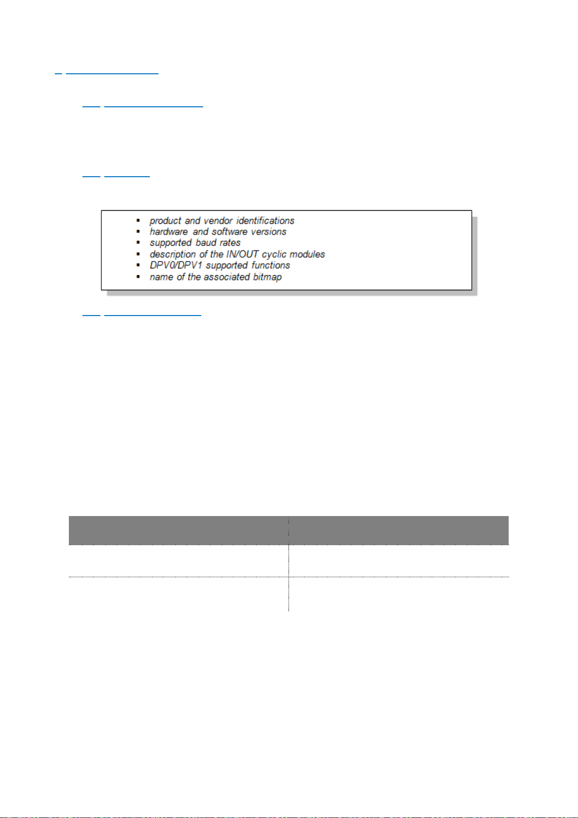
33/90
User manual SCAIME: NU-Soft-eNod4F-E-0716_235704-C.doc
7 PROFIBUS DPV1
7.1 Physical interface
An eNod4 device compatible version can be connected to a Profibus DPV1 network thanks to the SUBD 9-pin female
connector. eNod4 supports baud rates between 9600 kbps and 12 Mbps with automatic detection.
For a complete description of the recommendations about eNod4 Profibus DPV1 connection, please refer to
“Characteristics and functioning” documentation.
7.2 GSD file
eNod4 capabilities for Profibus communication are described in the corresponding GSD file (that can be easily read as
an ASCII text file). Here are the main information’s contained in this file:
7.3 Cyclic exchanges
7.3.1 Cyclic inputs modules
eNod4 GSD file defines several modules that can be integrated to the Profibus DP cyclic frames. All types of
measurements processed by eNod4 can be selected (net/gross/factory calibrated measurement). Moreover it is
possible to add the data that contain information about the measurement or the device status.
7.3.2 Cyclic inputs/outputs modules
eNod4 cyclic outputs might be used in combination with cyclic inputs so as to request specific commands to eNod4
(like tare, calibration...) or to modify the values of some settings (for example, set point values). A simple protocol
described below allows writing or reading data by writing commands into eNod4 cyclic outputs.
- The module “Reg. Command/Response” uses the eNod4 functional command mechanism defined in
another chapter. The only difference concerns the “reset” and “restore default parameters” commands
which cannot be sent via cyclic exchanges immediately after an eNod4 reboot. To use them with this
cyclic exchange module, another command should be used before (cancel tare for example).
The ‘command/response register’ described by eNod4 GSD file is constituted by 2 IN/OUT bytes and is
working almost the same way. Its functioning will be detailed later in this document.
- The ‘read/write request register’ described by eNod4 GSD file is constituted by 6 IN/OUT bytes :
IN
OUT
Transaction status (2 bytes)
Transaction request (2 bytes)
Data read/written (4 bytes)
Data to be written (4 bytes)
the Profibus DP master can transmit a read or write request to eNod4 by writing a specific code (see
the codes listed in the appendix) into the transaction request register.
for a write request, the 4 following OUT bytes can be used so as to enter the new value of the
accessed setting
eNod4 IN are then updated :
- Transaction status is set to 0xFFFF in case of an error otherwise it takes the same value as the
one entered in the transaction request word.
- For a read transaction, the value of the requested setting is copied into the four IN following
bytes.
- For a write transaction the value of the data to be written is copied into the four IN following
bytes.
Page 34

34/90
User manual SCAIME: NU-Soft-eNod4F-E-0716_235704-C.doc
- For 16-bits size data, the data is read/written through the 16 last bits. Ignore the 16 upper bits.
Note: the transaction request register must be set to 0x0000 before every new transaction.
7.4 Acyclic exchanges
For DPV1 class 1 and class 2 masters, another mechanism is available to write/read data into/from eNod4 device.
Acyclic exchanges are supported authorizing a class 1 master to send acyclic requests so as to read or write data into
memory area defined by a couple of slot/index.
A class 2 master can also send the same requests after initiating a connexion (up to 2) with eNod4. The
communication happens without disturbing the cyclic data exchange established between the device and the class 1
master.
Note: be careful when using acyclic read/write requests. The 4-bytes size data are transmitted as 2x16 bits
blocks that need to be inverted so as to keep their consistency. For example 500 000d (0007A120H) is
read/written through acyclic requests as A1200007H.
7.5 eNod4 Profibus DP features
7.5.1 Sync
The Sync command can be transmitted from a master to one or more slaves. When receiving this command, eNod4
device is set into Synchro mode. Thus, the cyclic outputs of all the addressed slaves are maintained in their current
state. The cyclic outputs state is not updated until a new Sync command is received. The Synchro mode stops upon
reception of a Unsync command.
7.5.2 Freeze
The reception of a Freeze command causes eNod4 cyclic inputs to be frozen. Their state is not updated until a new
Freeze command is received. The Frezze mode stops upon reception of an Unfreeze command.
7.5.3 Fail-safe
eNod4 supports the Profibus DP Fail-safe mode. When the Profibus DP master asks eNod4 to switch to Fail-Safe
mode, eNod4 functioning changes according to following rules:
eNod4 Profibus DP cyclic inputs goes on being refreshed
eNod4 Profibus DP cyclic outputs are no more received
eNod4 remains as a “read-only device” until the master goes back to a normal working mode.
7.5.4 Profibus DP standard and extended diagnoses
eNod4 diagnosis frame is composed of a standard and a specific (called extended) parts that allow to inform the
Profibus DP master about the device functioning on the communication bus and about device internal errors. The
Profibus diagnosis frame has the following structure:
bytes 1-4
bytes 5-6
byte 7
bytes 8-9
standard diagnosis
length of extended
diagnosis
extended diagnosis
content
status
1
status
2
status
3
Address
Ident Hi
Ident Low
03
XX XX (see table
below)
status 1 & status 2 bytes : both bytes describe eNod4 current state from the Profibus point of
view. Bit b3 of status 1 byte is set to 1 if the extended diagnosis contains one or several errors.
status 3 byte : always 00
H
Address : Profibus address if the DP master that parameterized eNod4 device
Ident. High/Ident. Low bytes : contain eNod4 ident number (0D2D
H
)
extended diagnosis content :
Page 35

35/90
User manual SCAIME: NU-Soft-eNod4F-E-0716_235704-C.doc
bits
meaning
note
b0
0
/
1
input analog signal out of the A/D
conversion range (negative quadrant)
b1
0
/
1
input analog signal out of the A/D
conversion range (positive quadrant)
b2 0
/
see §8 for the ‘maximum capacity’
setting description
1
gross meas.< (- max capacity)
b3
0
see §8 for the ‘maximum capacity’
setting description
1
gross meas. > (max capacity)
b4 0 EEPROM OK
1
Default EEPROM
b
15..... b5
0
reserved
7.6 Product identification
As a DPV1 compatible device, eNod4 supports record 0 of Identification and Maintenance (I&M0). A Profibus master
can access its content through standard DPV1 request.
7.7 Measurement transmission
In Profibus DPV1 communication protocol, measurements (except for tare value) can be included in the cyclic input
frame. The modular slave structure allows the user to select the variables according to his needs. These data cannot
be accessed through acyclic requests.
7.8 EEPROM error management
Functioning and calibration parameters are stored in EEPROM NOV RAM. After every reset the entireness of
parameters stored in EEPROM is checked. If a default appears, measurements are set to 0xFFFF and default is pointed
out into module 1 and bit b4 of extended diagnoses register.
Page 36

36/90
User manual SCAIME: NU-Soft-eNod4F-E-0716_235704-C.doc
8 PROFIBUS MODULES LIST
Name
Input data
size in byte
Provided data
Output data
consumed
size in byte
Consumed data
Module ID
Status+Gross
Meas.
(6 bytes IN)
6
Measurement status
(2 bytes)
0
NA
1
Gross measurement
(4 bytes)
StatIO+Net+Fact
(10 bytes IN)
10
Inputs – Outputs levels
(2 bytes)
0
NA
2
Net measurement
(4 bytes)
Factory calibrated points
(4 bytes)
Flow rates Meas..
(12 b IN)
12
Instant flow rate
(4 bytes)
0
NA
3
Average flow rate
(4 bytes)
Dosing quality factor
(4 bytes)
Output control
(6 bytes IN)
6
Flow rate control output
(4 bytes)
0
NA
4
Control output value
(2 bytes)
Totalization
(10 bytes IN)
10
Totalizer value (Great
WU)
(4 bytes)
0
NA
5
Complementary totalizer
value (2 bytes)
Totalization flow rate
(4 bytes)
Cmd/Resp Reg
(2 b IN/OUT)
2
Response register
2
Command
register
(see § functional
commands)
6
R/W req Reg.
(6 b IN/OUT)
6
Transaction status
(2 bytes)
6
Transaction
request
(2 octets)
7
Data read/written
(4 bytes)
Data to be
written (4 octets)
Status/Errors
(12 b IN)
12
Dosing status
(2 bytes)
0
NA
8
Dosing errors report
(2 bytes)
Page 37

37/90
User manual SCAIME: NU-Soft-eNod4F-E-0716_235704-C.doc
Name
Input data
size in byte
Provided data
Output data
consumed
size in byte
Consumed data
Module ID
Dosing errors counter
(2 bytes)
Last dosing error
(2 bytes)
Dosing quality factor
(4 bytes)
Other totals
(8 b IN)
8
Grand total in weight unit
x1000 (4 bytes)
0
NA
9
General total in weight
unit x1000 (4 bytes)
Ana. Output
(2 b IN/OUT)
2
External value to control
analog output (2 bytes)
2
External value to
control analog
output (2 bytes)
10
The module “Cmd/Resp Reg” uses the mechanism of eNod4 functional commands defined in another chapter. The
only difference is for “reset” and “Restore default settings” commands which cannot be sent via cyclic exchanges
immediately after a restart of eNod4. To be able to use these commands, it must first be processed another command
(“cancel Tare” for example).
Note: The “Command register” data must be set to 0x0000 before each new command.
The “Ana. Output(2 b IN/OUT)” module allows writing directly the analog output value. This is only possible when the
analog output function assignment is set to « Level on request ».
Page 38

38/90
User manual SCAIME: NU-Soft-eNod4F-E-0716_235704-C.doc
9 MEASUREMENT AND STATUS
Name
Modbus
address
CANopen®
Index/sub-
index
Profibus cyclic
IN/OUT
Acyclic DPV1
slot/index
Type
Access
Measurement status
0x007D
0x5003 / 0x00
(M)
Module 1
(2 first bytes)
/
Uint
RO
Gross measurement
0x007E
0x5001 / 0x00
(M)
Module 1
(4 last bytes)
/
Long
RO
Tare value
0x0080
0x5004 / 0x01
(M)
R 0x0470
/
Long
RO
Net measurement
0x0082
0x5000 / 0x00
(M)
Module 2
(4 bytes starting
3rd byte)
/
Long
RO
Factory calibrated points
0x0084
0x5002 / 0x00
(M)
Module 2
(4 last bytes)
/
Long
RO
Preset Tare
0x0097
0x5004 / 0x02
(M)
R: 0x04C4
W: 0x04C5
0x03 / 0x08
Ulong
RW
Defective measurement
debounced time
0x0A48
0x4509/0x06
R:0x0206
W:0x0207
0x06 / 0x0D
Uint
RW
Defective measurement alarm
activation time
0x0A49
0x4509/0x07
R:0x0208
W:0x0209
0x06 / 0x0E
Uint
RW
Sensor input control reference
0x0A44
0x5004 / 0x03
(M)
R : 0x044C
W: 0x044D
0x0A / 0x00
long
RW
Sensor input control result
0x0A46
0x5004 / 0x04
(M)
R : 0x024E
0x0A / 0x01
Int
RO
Sensor input control result
max. tolerance
0x0A47
0x5004 / 0x05
R: 0x020A
W: 0x020B
0x0A / 0x02
Uint
RW
9.1 Measurement transmission
The eNod4 transmits measurement after signal and data processing through different protocols available. The
accessible variables are:
9.1.1 Gross measurement
The ‘gross measurement’ stands for the digital value after measurement scaling. It is affected by all the ‘zero’
functions (power-up zero, zero tracking and zero requests).
9.1.2 Net measurement
The ‘net measurement’ stands for the digital value after measurement scaling and tare subtraction.
9.1.3 Tare value
The ‘tare value’ stores the calibrated value that is subtracted from the ‘gross measurement’ so as to give the ‘net
measurement’.
9.1.4 Factory calibrated points
The ‘factory calibrated points” contains the measurement value without the user calibration layer. It is directly linked
to the analog input voltage.
9.1.5 Preset Tare value
A previous calculated tare can be restored using this variable.
Page 39

39/90
User manual SCAIME: NU-Soft-eNod4F-E-0716_235704-C.doc
9.1.6 Measurement status
The measurement status contains information on eNod4 measurement parameters.
The ‘measurement status’ bytes contain information about every measurement processed by eNod4. See the flags
meaning in the table below:
bits
Meaning
Note
b1 b0
00
gross measurement
only in SCMBus/fast communication
protocols
not significant otherwise (00)
01
net measurement
10
factory calibrated measurement
11
tare value
b3 b2 00
measurement OK
01
Defect: sensor input control result out of
tolerances OR Sensor input control
command in progress OR failed (timeout)
OR Sensor input reference command in
progress
causes a logical output assigned to the
‘defective measurement’ function to be
set active. Causes the analog output
assigned to a weight or flow rate
image to be set in error mode.
10
gross meas.< (- max capacity) OR gross
meas. > (max capacity)
11
analog signal out of the A/D converter input
range
b4
0
motion
causes an output assigned to the
‘motion’ function to be set active
1
no motion
b5
0
measurement out of the ¼ of division
1
zero in the ¼ of division
b6 0
EEPROM OK
See Note 1
1
EEPROM failure
b7
0
reserved
1 in SCMBus and fast SCMBus, 0
otherwise 1 b8
0
IN1 logical level
1
b9
0
IN2 logical level
1
Page 40

40/90
User manual SCAIME: NU-Soft-eNod4F-E-0716_235704-C.doc
bits
Meaning
Note
b10
0
OUT1 logical level
1
b11
0
OUT2 logical level
1
b12
0
OUT3 logical level
1
b
13
0
OUT4 logical level
1
b
14
0
no tare
1
at least a tare has been processed
b
15
0
reserved
1 in SCMBus and fast SCMBus, 0
otherwise
1
Note 1: Functioning and calibration parameters are stored in EEPROM. After every reset the entireness of parameters
stored in EEPROM is checked. If a defect appears, measurements are set to 0xFFFF and defect is pointed out in
measurement status. Causes a logical output assigned to the ‘defective measurement’ function to be set active.
Causes the analog output assigned to a weight or flow rate image to be set in error mode.
9.2 Weighing diagnosis
9.2.1 Global weighing diagnosis
An internal alarm flag reflects the integrity of the whole measurement chain. It’s used to set logical output active or
optional analog output in an error mode in order to warn about any defection on the measurement chain (defective
measurement).
This variable is set active when at least one of the followings conditions occurs:
- all that set bit2 or bit3 of Measurement status:
• sensor input control result out of tolerances
• sensor input control command in progress
• sensor input control command failed (timeout)
• sensor input reference command in progress
• gross meas. < (- max capacity)
• gross meas. > (max capacity)
• analog signal out of the A/D converter input range
- the one that set bit6 of Measurement status: EEPROM failure
This internal alarm flag is featured with adjustable specific de-bounced time and minimal activation time:
9.2.1.1 Defective measurement debounced time
The internal alarm flag is set active only after error conditions have always been true during this de-bounced time. It’s
expressed in ms.
9.2.1.2 Defective measurement alarm activation time
The internal alarm flag remains active for this minimal “defective measurement alarm activation time” when it come
to be active and whatever the error conditions are during activation. It is expressed in ms.
Page 41

41/90
User manual SCAIME: NU-Soft-eNod4F-E-0716_235704-C.doc
9.2.2 Sensor input control
eNod4 features a weighing diagnosis system allowing to check the integrity of analog sensor input by electrically
simulating a load, resulting to a simulated weight value. This diagnostic system can be used together with the others
defects detection systems in order to achieve overall integrity check of the measurement chain. This system involves
two phases initiated by the user:
- The first, just after user calibration, allows taking a simulated reference weight value when the measuring
chain integrity is OK.
- The second, when the user wants to check the integrity of the system, allows to make the difference between
a new simulated weight value and the reference. Then this difference can be compared with a dedicated
maximum tolerance value.
9.2.2.1 Sensor input control reference
Reference value expressed in factory calibrated points for the sensor(s) input control test. The value is automatically
determined and stored after executing the sensor input reference command. When the sensor input reference
command is in progress the bits b3b2 in the Measurement status are set to 0b01. Its default value is zero.
9.2.2.2 Sensor input control result
Result of sensor(s) input control test expressed in 1/10 of user weight unit. Its value is automatically determined and
stored after executing the sensor input control command. This test result represents the weight difference between
the reference value and the current test value. It is set to -1 when the sensor input control command is in progress or
the command failed, these conditions cause the bits b3b2 in the Measurement status to be set to 0b01. Its default
value is zero.
9.2.2.3 Sensor input control result max. tolerance
The Sensor input control result variable is compared with the Sensor input control result max. tolerance parameter
which is expressed in 1/10 of user weight unit and has a default value of 30. If the sensor input control result value is
greater than or equal to Sensor input control result max. tolerance then the bits b3b2 in the Measurement status are
set to 0b01.
Page 42

42/90
User manual SCAIME: NU-Soft-eNod4F-E-0716_235704-C.doc
10 PROCESSING FUNCTIONAL COMMANDS
Name
Modbus
address
CANopen®
Index/sub-index
Profibus
cyclic IN/OUT
Acyclic
DPV1
slot/index
Type
Access
Command register
0x0090
0x2003 / 0x00 (M)
Module 6
/
Uint
RW
Response register
0x0091
0x2004 / 0x00 (M)
Module 6
/
Uint
RO
10.1 Principles
eNod4 device is able to handle several functional commands thanks to a couple of registers (except in SCMBus
protocols):
the command register : dedicated to accept the functional commands
the response register : gives the state of the command currently being processed by eNod4 (no command, in
progress, finished, failed)
• 00
H
free to accept a new command
• 01
H
command execution in progress
• 02
H
command execution complete
• 03
H
error during command execution
Note: IMPORTANT except in SCMBus/fast SCMBus protocols, to accept a new command, the command register must
be set to 00H first. This causes the response register to be set back to 00H.
Page 43

43/90
User manual SCAIME: NU-Soft-eNod4F-E-0716_235704-C.doc
10.2 Functional commands list
Functional command
Command
code
Note
Set to idle (00H) response register
00H
See § above
reset*
D0H
EEPROM storage
D1H
Restore default settings
D2H
Zero*
D3H
Tare*
D4H
Cancel tare*
D5H
Cancel current command
D6H
Theoretical scaling
D7H
Zero adjustment
D8H
Start physical calibration
D9H
physical calibration procedure
Calibration zero acquisition
DAH
Segment 1 acquisition
DBH
Segment 2 acquisition
DCH
Segment 3 acquisition
DDH
Store calibration
DEH
end of calibration (physical/theoretical)
procedure
OUT1 activation/deactivation*
E6H
only possible if the outputs are assigned to
the associated function
OUT2 activation/deactivation*
E7H
OUT3 activation/deactivation*
E8H
OUT4 activation/deactivation*
E9H
zero offset adjustment
F0H
Dynamic zero acquisition
F1H
Preset tare*
F2H
Sensor input reference
EFH
Sensor input control
FDH
Totalization / errors clear
DFH
Dosing / batch start / resume
E4H Dosing / batch stop / cancel
E5H
Suspend batch
F7H
Emptying hopper (cleaning)
F4H
Refilling start
F5H
Page 44

44/90
User manual SCAIME: NU-Soft-eNod4F-E-0716_235704-C.doc
Functional command
Command
code
Note
Refilling stop
F6H
Learning cycle on next cycle
F3H
Auto Measurement in two points for flow
rate calibration
C9H
Auto Measurement in three points for flow
rate calibration
CAH
Flow rate calibration
F8H
PID parameters auto-adjustment
F9H
Clear grand total
EDH
Clear general total
EEH
Note: only the commands with a * can be handled by eNod4 in SCMBus and fast SCMBus protocols.
10.3 Functional commands description
10.3.1 Reset
The ‘reset’ functional command execution is similar to the device power-up. This reboot phase is necessary if the
address or/and the baud rate are modified and some settings changes are only taken into account after an EEPROM
storage followed by a reset.
10.3.2 EEPROM storage
eNod4 configuration and calibration are stored in a non-volatile memory (EEPROM). If changes are made in the device
configuration, sending to eNod4 the ‘EEPROM storage’ functional command will allow eNod4 to keep these
modifications after a power shutdown or the reception a ‘reset’ functional command.
Moreover the settings listed below need to be stored and will only be taken into account at the next device reboot:
• span adjusting coefficient
• calibration place g value
• place of use g value
• stability criterion
• legal for trade activation switch
• power-up zero
• A/D conversion rate
• Functioning mode and communication protocol
• Analog output voltage and current
10.3.3 Restore default settings
The ‘restore default settings’ command causes eNod4 to be set back to its default configuration. The default
configuration corresponds to the one on delivery that means with factory settings. Be careful when using this
command, all the default settings are recovered including the stored calibration and the legal for trade indicators.
Note: this functional command is not available in CANopen® communication protocol.
10.3.4 Zero
When receiving a ‘zero’ functional command, eNod4 acquires a volatile zero (gross measurement is set to 0) value if
the following conditions are respected:
• measurement is stable
• Current gross measurement is within a ±10% (±2% if the legal for trade option is enabled) range of the
‘maximum capacity’.
Otherwise, after five seconds the command is cancelled and an execution error is reported. This value is not stored in
EEPROM.
Page 45

45/90
User manual SCAIME: NU-Soft-eNod4F-E-0716_235704-C.doc
10.3.5 Tare
When receiving a ‘tare’ functional command, eNod4 acquires a volatile tare (net measurement is set to 0) value if the
measurement is stable otherwise, after five seconds the command is cancelled and an execution error is reported. If
the tare acquisition is successful b14 bit of the ‘measurement status’ is set to 1.
10.3.6 Cancel tare
This command erases the current tare value if at least one tare has been previously processed. It also causes b14 bit of
the ‘measurement status’ to be set back to 0.
10.3.7 Cancel last command
This command sets the response register to 00H and allows eNod4 to ignore the functional command previously
received and not yet issued (for example to exit a sequential procedure like a physical calibration).
10.3.8 Theoretical scaling
The ‘theoretical scaling’ functional command involves the ‘maximum capacity’ and the ‘sensor sensitivity’ settings.
When used, this command realizes an automatic scaling to migrate from the factory calibration to the user calibration.
This calibration must then be saved by sending to eNod4 the ‘store calibration’ functional command. Using the ‘zero
adjustment’ functional command is also recommended so as to completely adapt eNod4 to the application.
10.3.9 Zero adjustment
The ‘zero adjustment’ functional command allows the user to set his calibration zero value by asking eNod4 to acquire
the current factory calibrated measurement. This acquisition duration depends on the measurement stability; if
stability is not reach after 5 seconds, ‘zero adjustment’ command is cancelled and an execution error is reported. If it
is correctly achieved, this calibration zero modification must then be saved by sending to eNod4 the ‘store calibration’
functional command. This functional command can be used any time and has no effect on the user-span that can have
been previously configured through a physical or a theoretical calibration procedure.
10.3.10 Start physical calibration
In order to handle a physical calibration with 1 up to 3 know references, eNod4 first must be told to enter the physical
calibration mode. It is the first step of a sequential procedure.
10.3.11 Calibration zero acquisition
The ‘calibration zero acquisition’ is the second step of the physical calibration procedure. It can only be used if the
‘start physical calibration’ functional command has been previously received. This acquisition duration depends on the
measurement stability; if stability is not reach after 10 seconds, ‘calibration zero acquisition’ command is cancelled
and an execution error is reported.
Note: In specific cases (silo for example), this step is not mandatory because it is possible to command a “zero
adjustment” when the silo is empty.
10.3.12 Segment 1 acquisition
It consists in applying a known reference on the sensor then sending the ‘segment 1 acquisition’ functional command.
This acquisition duration depends on the measurement stability; if stability is not reach after 10 seconds, ‘actual
segment acquisition’ command is cancelled and an execution error is reported.
10.3.13 Segment 2/3 acquisition
Only if the ‘calibration zero acquisition’ and “Segment 1 acquisition” are successful, next step consists in applying a
known reference on the sensor then sending the ‘segment X acquisition’ functional command where X depends on the
value stored in the ‘number of calibration segments’ register. This acquisition duration depends on the measurement
stability; if stability is not reach after 10 seconds, ‘actual segment acquisition’ command is cancelled and an execution
error is reported.
10.3.14 Store calibration
Only if the ‘segment 1/2/3 acquisition’ is successful, next step consists in validating the new calibration by storing the
zero and the span that have been determined in EEPROM.
Note: This functional command has to be transmitted at the end of a physical calibration, after a ‘zero adjustment’, a
‘theoretical scaling’ or a ‘zero offset’.
10.3.15 Logical outputs 1-4 activation/deactivation
If the corresponding logical outputs are assigned to the ‘level on request’ function, they can be enabled/disabled by
transmitting one of these functional commands. Upon first reception, the corresponding output is enabled and on
next reception it will be disabled. If the requesting logical output is assigned to the wrong function, eNod4 reports an
error.
Page 46

46/90
User manual SCAIME: NU-Soft-eNod4F-E-0716_235704-C.doc
10.3.16 Zero offset adjustment
It is also possible to adjust the calibration zero value without acquiring a new one. By entering a positive or negative
value into the ‘delta zero’ register, the user can quantify the offset (in factory calibrated points) that has to be added
or subtracted from the actual calibration zero. This calibration zero modification must then be saved by sending to
eNod4 the ‘store calibration’ functional command.
10.3.17 Dynamic zero acquisition
When receiving a dynamic zero acquisition command eNod4 calculates the average of successive weight measures
during the time specified in dynamic zero acquisition time parameter. A new zero is then used if the averaged value is
within a ±10% (±2% if the legal for trade option is enabled) range of the maximum capacity.
There is no stability criteria required. Dynamic zero acquisition can also be launch by an input assigned to this
function. Dynamic zero acquisition can be interrupted by sending cancel current command.
10.3.18 Preset tare
With this command it is possible to retrieve a tare value defined previously.
Important: Preset tare parameter value must be stored before sending this command.
10.3.19 Sensor input reference
Sensor input reference command will cause eNod4 to handle special sequence to acquire sensor input control
reference value of the load cell sensor input. This command must not be realized when any process cycle that use
weight is in progress (because weight variables do not reflect the real weight whilst command is in progress). This
command can fail (error in response register) in case of stability timeout on sensor input. The execution time of this
command depends on the weight filtering settings. For any further information about this functionality and result
variables see “Weighing diagnosis” § in the MEASUREMENT AND STATUS §.
10.3.20 Sensor input control
Sensor input control command will cause eNod4 to handle special test on sensor input and to deliver a test result. This
command must not be realized when any process cycle that use weight is in progress (because weight variables do not
reflect the real weight whilst command is in progress). This command can fail (error in response register) in case of
stability timeout on sensor input. The execution time of this command depends on the weight filtering settings. For
any further information about this functionality and result variables see “Weighing diagnosis” § in the MEASUREMENT
AND STATUS §.
10.3.21 Clear totalization & errors counter
This command triggers the main totalizer reset. The two parts of the totalizer, the main in weight unit x 1000, and the
complementary part in weight unit are then reset.
The variables dosing errors report, dosing errors counter and last dosing error are also reset.
10.3.22 Dosing / batch start / resume
In batch mode this command launches or resumes a cycle. A cycle can also be launched by an input assigned to this
function. When the command is sent through the command register, eNod4 answers back the control state value
through the response register.
This command will not issue if a flow rate calibration has not been previously performed.
When a cycle starts and depending on parameters setting of eNod4, there will be firstly a refilling. Totalizer may be
cleared and a learning cycle initiated.
If a batch has been previously suspended, this command allows resuming the cycle and the totalization. The dosing
status variable allows monitoring enod4 state during the dosing cycle.
Attention: an input can only be assigned to start/stop dosing or suspend/resume batch, with a functioning in a
bistable mode and on rising or falling front depending on the selected logic.
10.3.23 Dosing stop / batch cancel
In loss in weight feeder mode, this command allows stopping the running dosing cycle. If a batch is pending, it will be
stopped with any possible resumption.
Attention: an input can only be assigned to start/stop dosing or suspend/resume batch, with a functioning in a
bistable mode and on rising or falling front depending on the selected logic.
10.3.24 Suspend batch
In batch mode this command suspends dosing. It allows any cleaning operation without clearing a batch. Launching a
Dosing / batch start/ resume command will resume the dosing cycle.
Page 47

47/90
User manual SCAIME: NU-Soft-eNod4F-E-0716_235704-C.doc
Warning: an input can only be assigned to suspend/resume batch, with a functioning in a bistable mode and on rising
or falling front depending on the selected logic.
10.3.25 Emptying hopper (cleaning)
In loss in weight feeder mode, this command allows to automatically emptying the hopper (or silo) in preparation of a
cleaning process or for changing the dosing product. Dosing is running and totalization works until the gross weight
reaches the empty hopper level.
An input can be assigned to start/stop hopper emptying, with a functioning in a bistable mode and on rising or falling
front depending on the selected logic. It's not possible to suspend an emptying.
The command start/stop dosing or suspend/resume batch systematically lead to the emptying shutdown.
10.3.26 Refilling start
This command allows refilling activation. Refilling stops when the gross weight reaches the refilling high level minus
the refilling inflight value. Inflight value is not adjusted automatically at each cycle.
Refilling can also be initiated/stopped by an input assigned to start/stop refilling, with a functioning in a bistable
mode and on rising or falling front depending on the selected logic.
10.3.27 Refilling stop
This command will stop refilling immediately. Refilling can also be initiated/stopped by an input assigned to start/stop
refilling, with a functioning in a bistable mode and on rising or falling front depending on the selected logic.
10.3.28 Learning cycle on next cycle
If PID activation, smart refill mode and acquisition of flow rate refill references on learning cycle options are
activated, this command will launch a learning cycle after the next refilling phase. This smart refill mode compensates
for the flow rate variation due to the product thrust in the hopper or silo so that the flow rate always remains
constant throughout the phase. New values for reference flow rate control output start refilling and reference flow
rate control output end refilling parameters will be determined.
10.3.29 Flow rate calibration
So that eNod4 can carry out an expected flow rate dosing in the best possible conditions, the flow rate calibration is
required. This also applies when eNod4 is used both as constant flow rate totalizer and as loss in weight feeder.
From this calibration will depend the accuracy of the flow rate obtained and on the settling time, if a PID controller is
activated. This calibration is carried out in minimum two segments by the variable segments number for the
calibration curve of flow rate. In case the extraction device has a nonlinear response it is recommended to define
maximum segments for the flow rate calibration.
In order to calibrate the flow rate, if the control of extraction device is directly provided by eNod4 through an analog
control output in current or voltage, analog output functioning of eNod4 must be allocated to level on request
function first.
For each calibration point of the variable control output value, read the appropriate average flow rate. Then provide
each of the Calibration of flow rate point n (control output) and Calibration of flow rate point n (flow rate value)
matching with control output value.
Validate the flow rate calibration by sending calibration of flow rate command.
Finally allocate in the end the current or voltage analog output of eNod4 to flow rate control output function.
10.3.30 Auto Measurement in two or three points for flow rate calibration
In order to calibrate the flow rate, if the control of extraction device is directly provided by eNod4 through
an analog control output in current or voltage, analog output functioning of eNod4 must be allocated to
level on request function first. There are two commands, the first allows automatic measurement of flow
rate in two points (35% & 70% of control output). The second allows automatic measurement of flow rate
in three points (20%, 50% & 80%).
At the end of procedure, the flow rate calibration is validating automatically.
10.3.31 PID parameters auto-adjustment
The configuration of the PID controller can be made in a totally automatic way. The behavior of PID controller (slow,
fast or stable) must be previously configured. You have also to configure PID adjustment flow rate parameter that will
be used for PID auto-adjustment.
Page 48

48/90
User manual SCAIME: NU-Soft-eNod4F-E-0716_235704-C.doc
So that this controller automatic adjusting device works, both the weight calibration and the flowrate calibration
must be previously carried out.
PID parameters auto-adjustment command will cause eNod4 to perform successive dosing cycle sequence to
calculate optimized PID coefficients Kp, Ti and Td. The number of cycle sequence can be fixed by user (parameter).
It is strongly recommended that Td parameter does not exceeded value 5.
10.3.32 Clear grand total
Clear great total command allows individual reset of Grand total (in weight unit x1000) totalizer.
10.3.33 Clear general total
Clear general total command allows individual reset of General total (in weight unit x1000) totalizer.
Page 49

49/90
User manual SCAIME: NU-Soft-eNod4F-E-0716_235704-C.doc
11 CALIBRATION SETTINGS AND PROCEDURES
Name
Modbus
address
CANopen®
Index/sub-
index
Profibus cyclic
IN/OUT
Acyclic DPV1
slot/index
Type
Access
Maximum capacity
0x000C
0x3002 / 0x00
(M)
R : 0x0420
W: 0x0421
0x02 / 0x00
Ulong
RW
Number of calibration
segments
0x000E
0x3000 / 0x00
R : 0x0222
W: 0x0223
0x02 / 0x01
Uint
RW
Calibration load 1
0x000F
0x3001 / 0x01
(M)
R : 0x0424
W: 0x0425
0x02 / 0x02
Ulong
RW
Calibration load 2
0x0011
0x3001 / 0x02
R : 0x0426
W: 0x0427
0x02 / 0x03
Ulong
RW
Calibration load 3
0x0013
0x3001 / 0x03
R : 0x0428
W: 0x0429
0x02 / 0x04
Ulong
RW
Sensor sensitivity
0x0015
0x3004 / 0x00
(M)
R : 0x042A
W: 0x042B
0x02 / 0x05
Ulong
RW
Scale interval
0x0017
0x3003 / 0x00
R : 0x022C
W: 0x022D
0x02 / 0x06
Uint
RW
Zero calibration
0x0018
0x3005 / 0x00
R : 0x0434
W: 0x0435
0x03 / 0x04
Long
RW
Span coefficient 1
0x001A
0x3006 / 0x04
R : 0x0436
W: 0x0437
0x03 / 0x05
Float
RW
Span coefficient 2
0x001C
0x3006 / 0x05
R : 0x0438
W: 0x0439
0x03 / 0x06
Float
RW
Span coefficient 3
0x001E
0x3006 / 0x06
R : 0x043A
W: 0x043B
0x03 / 0x07
Float
RW
Span adjusting coefficient
0x0020
0x3006 / 0x01
(M)
R : 0x042E
W: 0x042F
0x03 / 0x00
Ulong
RW
Calibration place g value
0x0022
0x3006 / 0x02
R : 0x0430
W: 0x0431
0x03 / 0x01
Ulong
RW
Place of use g value
0x0024
0x3006 / 0x03
R : 0x0432
W: 0x0433
0x03 / 0x02
Ulong
RW
Zero offset
0x0092
0x2500 / 0x00
(M)
R : 0x0472
W: 0x0473
0x03 / 0x03
Long
RW
11.1 Principles
eNod4 is factory calibrated to deliver 500 000 counts for 2mV/V with a load cell on the A3 input connector.
The measurement scaling in eNod4 can be adapted to his application by the user. Some settings and the 2 calibration
methods allow the user to define his specific span according to his sensors characteristics.
When using eNod4 for legal for trade purpose, it is
imperatively required to activate the legal for trade switch
BEFORE any calibration procedure (cf § legal for trade switch).
!
Page 50

50/90
User manual SCAIME: NU-Soft-eNod4F-E-0716_235704-C.doc
11.2 Calibration methods
Measurement scaling can be defined using one of the two following methods:
• Theoretical calibration involving the sensitivity of the sensor and a user-defined corresponding
capacity
• Physical calibration involving 1, 2 or 3 know loads (for a load cell)
Both can be achieved thanks to the functional commands.
11.3 Settings description
11.3.1 Maximum capacity
The ‘maximum capacity’ stands for the maximum sensor/load cell signal range. When the absolute value of the gross
measurement exceeds its value plus 9 divisions, the b3 bit (positive overloading) or the b2 bit (negative overloading) of
the measurement status is set to 1 (it can activate a logical output if it is assigned to the ‘defective measurement’
function).
The zero acquisition (on request or at power-up) is done only if the gross measurement value is contained between a
±10% range of the ‘maximum capacity’ (±2% if the legal for trade option is active).
The ‘maximum capacity’ setting also allows calibrating eNod4 in case of a theoretical calibration in association with
the sensor sensitivity. Measurement scaling will be automatically adapted so as to deliver a gross measurement value
equivalent to the ‘maximum capacity’ for an analog signal corresponding to the sensor sensitivity.
After a theoretical calibration, the maximum capacity can be changed to fit to the application.
Admitted values : from 1 up to 10000000.
11.3.2 Number of calibration segments
The ‘number of calibration segments’ defines how many calibration segments are used during the physical calibration
procedure. Linear installations only need one segment.
Admitted values : from 1 up to 3.
11.3.3 Calibration loads 1/2/3
Before starting a physical calibration procedure, each calibration segment must be given a corresponding user value
(for example, 1000 points for a 1 kg load).
Admitted values : from 1 up to 10000000.
11.3.4 Sensor sensitivity
The ‘sensor sensitivity’ setting is used to achieve a theoretical calibration. The stored value for this parameter is the
load cell sensitivity in mV/V.
The user can adapt the value delivered by eNod4 for the associated signal using the ‘maximum capacity’ and the
‘sensor sensitivity’.
This setting is expressed with a 10-5 factor (197500 is equivalent to a 1.975 mV/V load cell sensitivity or a 1.975 V input
voltage).
Admitted values : from 1 up to 1000000.
11.3.5 Scale interval
The ‘scale interval’ is the minimal difference between two consecutive indicated values (either gross or net).
Modification of scale interval is taking into account after a new calibration.
Admitted values : 1/2/5/10/20/50/100
11.3.6 Zero calibration
Zero calibration value corresponds to the A/D converter points measured during the ‘zero acquisition’ step of a
physical calibration.
For a theoretical calibration this value must be set. It can be set automatically with the ‘zero adjustment’ command.
Note: To be applied, any modification of this setting must be followed by an EEPROM back up and device reboots
(hardware or software).
Admitted values : from 0 up to +-10000000
11.3.7 Span coefficients 1/2/3
These coefficients are computed and written during calibration process. Writing these coefficients could be done if
you want to restore a previous calibration.
Note: To be applied, any modification of this setting must be followed by an EEPROM back up and device reboots
(hardware or software).
Admitted values : different from 0.
Page 51

51/90
User manual SCAIME: NU-Soft-eNod4F-E-0716_235704-C.doc
11.3.8 Span adjusting coefficient
The ‘span adjusting coefficient’ allows adjusting initial calibration. Adjustment applies linearly on the whole calibration
curve. This coefficient has a 10-6 factor (1000000 is equivalent to a span adjusting coefficient that is equal to 1).
Note: To be applied, any modification of this setting must be followed by an EEPROM back up and device reboots
(hardware or software).
Admitted values : from 900000 up to 1100000.
11.3.9 Calibration place g value / place of use g value
When the calibration place and the place of use of a measuring chain are different, a deviation can appear due to the
difference of g (gravity) between the 2 places.
The eNod4 calculates a ratio applied to the measure which compensates the difference of gravity between the 2
places.
The g value are expressed in 10-6 m.s-2 (9805470 is equivalent to g = 9.805470 m.s-2).
The eNodView software can help to determine the g value of a place.
Note: To be applied, any modification of this setting must be followed by an EEPROM back up and device reboots
(hardware or software).
Admitted values : different from 0.
11.3.10 Zero offset
The ‘Zero offset’ value contains the offset in factory calibrated points that can be added/subtracted (if its value is
positive or negative) to the zero calibration value when using the ‘zero offset’ functional command. Once the
command has been successfully achieved, this register is set to 0.
Note: The ‘Zero offset’ value is not stored into EEPROM memory and is always equal to 0 after a device power-up or a
software reset
Admitted values: different from 0.
Page 52

52/90
User manual SCAIME: NU-Soft-eNod4F-E-0716_235704-C.doc
12 FILTERS
Name
Modbus
address
CANopen®
Index/sub-
index
Profibus cyclic
IN/OUT
Acyclic DPV1
slot/index
Type
Access
A/D conversion rate
0x0036
0x4000 / 0x00
R : 0x0240
W: 0x0241
0x04 / 0x00
Uint
RW
filters activation
0x0037 LSB
0x4001 / 0x01
(byte)
R : 0x0242
W: 0x0243
0x04 / 0x01
Byte
RW
Low-pass order
0x0037 MSB
0x4001 / 0x02
(byte)
Byte
Low-pass cut-off frequency
0x0038
0x4001 / 0x03
R : 0x0244
W: 0x0245
0x04 / 0x02
Uint
RW
Depth of moving average filter
on weight
0x0039
0x4001 / 0x04
R : 0x0246
W: 0x0247
0x04 / 0x03
Uint
RW
Tolerance of clipping filter on
instant flow rates
0x003A
0x4001 / 0x05
R : 0x0248
W: 0x0249
0x04 / 0x04
Uint
RW
Average flow rate determination
depth
0x0059
0x4700 / 0x03
R : 0x0278
W: 0x0279
0x07 / 0x02
Uint
RW
12.1 Principles
eNod4 contains 4 filtering layers that are user-configurable :
• filtering related to the A/D conversion rate (with rejection of the mains frequency)
• a low-pass Bessel-type filter
• a moving average weight filter
• a self-adaptive filter
Except for the A/D conversion rate that is always enabled, none of these filters is mandatory. However, to perform
accurate measurements we recommend setting a combination of filters. eNodView software may be helpful in
designing the best filter configuration for the application.
Page 53

53/90
User manual SCAIME: NU-Soft-eNod4F-E-0716_235704-C.doc
12.2 Settings description
12.2.1 A/D conversion rate
It contains a code which represents the A/D conversion rate and the rejection. See table below:
b4
Rejection
0
60 Hz
1
50 Hz
b3 b2 b1 b0
A/D conversion rate (measures/s)
50-Hz rejection
60-Hz rejection
0000
100
120
0001
50
60
0010
25
30
0011
12.5
15
0100
6.25
7.5
1001
1600*
1920*
1010
800*
960*
1011
400*
480*
1100
200
240
* values that can only be selected in transmitter mode.
Note: To be applied, any modification of this setting must be followed by an EEPROM back up and device reboots
(hardware or software).
12.2.2 Filters activation & order
This setting allows to define what filters are enabled in eNod4 signal processing chain.
Note: the filters activation & order setting can be accessed through a 16-bits register except in CANopen®
communication protocol where this word is divided into 2 8-bits registers:
b1
Meaning
0
self-adaptive filter disabled
1
self-adaptive filter enabled
b10 b9 b8
000
low-pass filter disabled
010
2nd order low-pass filter
011
3rd order low-pass filter
100
4th order low-pass filter
Note: In CANopen® communication protocol (according to version), this word is divided into 2 bytes of 8-bits registers.
Bits b8 to b15 are therefore equivalent to bits b0 to b7 of the corresponding address (see CANopen® Register table).
12.2.3 Low-pass filter cut-off frequency
This register contains the low-pass filter cut-off frequency expressed in Hz and multiplied by 100. That means that 690
is equivalent to 6.90 Hz. The value must be compliant with the table shown below.
Admitted values: from 10 up to 20000.
Page 54

54/90
User manual SCAIME: NU-Soft-eNod4F-E-0716_235704-C.doc
12.2.4 Limitations
Recursive filters like eNod4 low-pass filters are computed according to the filter order, the desired cut-off frequency
and the sampling rate. There are some limitations to respect in order to ensure a safe functioning of the signal
processing. They are listed in the table below:
A/D conversion rate
(meas/s)
min low-pass cut-off
frequency (Hz)
A/D conversion
rate (meas/s)
min low-pass cut-off
frequency (Hz)
50 Hz rejection
60 Hz rejection
2nd order
3rd order
2nd order
3rd order
6.25
0.10
0.10
7.5
0.10
0.10
12.5
0.10
0.10
15
0.10
0.15
25
0.10
0.15
30
0.15
0.20
50*
0.15
0.25
60*
0.20
0.30
100*
0.25
0.50
120*
0.30
0.60
200*
0.50
1.00
240*
0.60
1.20
400
1.00
2.00
480
1.20
2.40
800
2.00
4.00
960
2.40
4.80
1600
4.00
8.00
1920
4.80
9.60
(*) values of A/D conversion rate that are accessible in feeder mode.
12.2.5 Depth of moving average filter on weights
A moving average filter on weight can be set in cascade after previous filters. This filter is used to smooth the weight
value in case of random interferences. If enable, this filter computes the mean of a specified last number of measures
which are output of the previous filters. The number of measures is defined by depth of moving average filter on
weights parameter. A high filter depth will give a better stability, with a longer response time.
Filter depth admitted values: 0(disabled) up to 128.
12.2.6 Tolerance of clipping filter on instant flow rates
When eNod4 is used in loss in weight feeder, it's possible to operate a clipping filter on the successive values of flow
rate. Clipping range is defined in 0.1% of the nominal flow rate. This filter will substitute flow rate values outside the
clipping range by the meaning of precedent flow rate values. It allows to suppress short asynchronous physical
disturbances on weight measures due to the environment. The filter is disabled when parameter is cleared.
12.2.7 Average flow rate determination depth
This parameter specifies the depth of the moving average filter on successive instant flow rate values in order to
produce the average flow rate. The average flow rate is only produced for display and generally it is appropriate to set
average flow rate determination depth parameter to the maximal value 128. The filter is disabled when parameter is
cleared.
Page 55

55/90
User manual SCAIME: NU-Soft-eNod4F-E-0716_235704-C.doc
13 CONFIGURATION OF INPUT/OUTPUT
Name
Modbus
address
CANopen®
Index/sub-
index
Profibus cyclic
IN/OUT
Acyclic DPV1
slot/index
Type
Access
Logical input 1 functioning
0x0042 LSB
0x4501 / 0x02
R : 0x0250
W: 0x0251
0x05 / 0x00
byte
RW
Logical input 2 functioning
0x0042 MSB
0x4501 / 0x03
byte
Logical input 3 functioning
(IO+ version)
0x0041 LSB
0x4501 / 0x04
R : 0x026A
W: 0x026B
0x05 / 0x02
byte
RW
Logical input 4 functioning
(IO+ version)
0x0041 MSB
0x4501 / 0x05
byte
holding time
0x0043
0x4501 / 0x01
R : 0x0252
W: 0x0253
0x05 / 0x01
Uint
RW
Analog output functioning
(IO+ version)
0x0040
0x4509 / 0x05
R : 0x026C
W: 0x026D
0x06 / 0x0B
Uint
RW
External value to control analog
output (IO+ version)
0x0032
0x5050 / 0x00
(M)
R : 0x023C
W: 0x023D
+ See modules
list
0x06 / 0x0C
Uint
RW
Output 1 functioning
0x0044 LSB
0x4509 / 0x01
R : 0x0254
W: 0x0255
0x06 / 0x00
byte
RW
Output 2 functioning
0x0044 MSB
0x4509 / 0x02
byte
Output 3 functioning
0x0045 LSB
0x4509 / 0x03
R : 0x0256
W: 0x0257
0x06 / 0x01
byte
RW
Output 4 functioning
0x0045 MSB
0x4509 / 0x04
byte
Weight quantity per pulse on
logical output
0x0057
0x4707 / 0x00
R : 0x02AE
W: 0x02AF
0x07 / 0x1D
Uint
RW
Set point 1 high value
0x0046
0x4601 / 0x02
R : 0x025A
W: 0x025B
0x06 / 0x02
Long
RW
Set point 1 low value
0x0048
0x4601 / 0x03
R : 0x025C
W: 0x025D
0x06 / 0x03
Long
RW
Set point 2 high value
0x004A
0x4601 / 0x04
R : 0x025E
W: 0x025F
0x06 / 0x04
Long
RW
Set point 2 low value
0x004C
0x4601 / 0x05
R : 0x0260
W: 0x0261
0x06 / 0x05
Long
RW
Set point 3 high value
0x004E
0x4609 / 0x02
R : 0x0262
W: 0x0263
0x06 / 0x06
Long
RW
Set point 3 low value
0x0050
0x4609 / 0x03
R : 0x0264
W: 0x0265
0x06 / 0x07
Long
RW
Set point 4 high value
0x0052
0x4609 / 0x04
R : 0x0266
W: 0x0267
0x06 / 0x08
Long
RW
Set point 4 low value
0x0054
0x4609 / 0x05
R : 0x0268
W: 0x0269
0x06 / 0x09
Long
RW
1&2 Set points functioning
0x0056 LSB
0x4601 / 0x01
R : 0x0258
0x06 / 0x0A
byte
RW
Page 56

56/90
User manual SCAIME: NU-Soft-eNod4F-E-0716_235704-C.doc
Name
Modbus
address
CANopen®
Index/sub-
index
Profibus cyclic
IN/OUT
Acyclic DPV1
slot/index
Type
Access
3&4 Set points functioning
0x0056 MSB
0x4609 / 0x01
W: 0x0259
byte
Logical input level
0x0094 LSB
0x5100 / 0x00
(M)
Module 2
/
Byte
RO
Logical ouput level
0x0094 MSB
0x5200 / 0x00
(M)
Byte
13.1 Principles
eNod4 device is fitted with 2 logical inputs (4 logical inputs for IO+ version) and 4 logical outputs that are fully
configurable.
13.1.1 Logical inputs
Each input can work individually in positive or negative logic. A holding time (de-bounced time) attached to all inputs
can be configured.
Available functions see hereunder table:
Function
Operating mode
transmitter
Loss in weight feeder
None
●
●
Tare
●
●
Cancel tare
●
●
Zero
●
●
Transmit measurement
(in SCMBus/fast SCMBus, in CANopen TPDO2
sending if input 1, TPDO3 sending if input 2)
●
Continuous measurement transmit
(SCMBus/fast SCMBus only)*
●
Dynamic zero
● ● Start/Stop refilling**
●
Start/Stop emptying hopper**
●
Start/Stop dosing**
● Suspend/Resume batch**
●
Emergency stop
●
Reset totalization and dosing error counter
●
Sensor input control
●
●
* command operates on logical level
** these commands operates on front in a bistable functioning mode. For example for the Start/Stop refilling
command, the first front initiates refilling, the second stops it.
Page 57

57/90
User manual SCAIME: NU-Soft-eNod4F-E-0716_235704-C.doc
Note: Most of functions set to logical inputs can also be sent by ‘functional commands’; for a precise description see §
‘functional commands’.
• None : the input has no function
• Tare : a rising (positive logic) or a falling edge (negative logic) causes a tare function to be triggered .
• Cancel tare : a rising (positive logic) or a falling edge (negative logic) causes the current stored tare to be
erased.
• Zero : a rising (positive logic) or a falling edge (negative logic) causes a zero function to be triggered.
• Transmit measurement : only available in CANopen® and SCMBus/fast SCMBus protocols and in
transmitter mode only. A rising (positive logic) or a falling edge (negative logic) triggers a measurement
transmission.
• Continuous transmit measurement : only available in SCMBus/fast SCMBus protocols. Measurements are
continuously transmitted at a rate defined by the measurement transmission period parameter while the
input is maintained at the chosen level.
• Dynamic zero : this input activation will cause eNod4 to perform zero function. This zeroing acquisition is
not conditioned by stability criterion and consists in a moving average of measures during an adjustable
parameter dynamic zero acquisition time. The new current zero is not stored permanently and can be
canceled by a reset of the module.
• Start/Stop refilling : this command operates on front in a bistable functioning mode. In dosing mode, the
first rising or falling edge (according to the configured logic) on this input causes a refilling procedure. The
second one will stop it.
• Start/Stop emptying hopper : this command operates on front in a bistable functioning mode. In dosing
mode, the first rising or falling edge (according to the configured logic) on this input causes an emptying
procedure. The second one will stop it.
• Start/Stop dosing : this command operates on front in a bistable functioning mode. In dosing mode, the
first rising or falling edge (according to the configured logic) on this input starts dosing. The second one
stops it.
• Suspend/Resume batch : this command operates on front in a bistable functioning mode. In dosing mode,
the first rising or falling edge (according to the configured logic) on this input suspends the batch. The
second one resumes it.
• Emergency stop : a rising (positive logic) or a falling edge (negative logic) triggers an emergency stop which
immediately stops the dosing, the totalization and eventually the refilling.
• Reset totalization and dosing error counter : a rising (positive logic) or a falling edge (negative logic)
triggers the main totalizer reset. Both parts of the totalizer, the main in weight unit x1000 and the
complementary part in weight unit are then reset.
The dosing errors counter variable is also reset.
• Sensor input control : a rising (positive logic) or a falling edge (negative logic) triggers a test routine of the
sensor input and produces a test result.
13.1.2 Analog output (IO+ version)
An optional analog board in current and voltage might be used with eNod4 to provide IO+ version. This must be asked
when ordering eNod4 product.
Voltage output might be set either 0-5V or 0-10V, and the current output to 4-20mA, 0-24mA , 0-20mA or 4-20mA
with alarm at 3.6mA. Both output (current and voltage) might separately be enable. Settings are effective after eNod4
reset.
Analog output affectation function is common to both current and voltage output and might be assigned to
followings:
Page 58

58/90
User manual SCAIME: NU-Soft-eNod4F-E-0716_235704-C.doc
function
Operating mode
transmitter
loss in weight feeder
none ● ●
gross measurement ● ●
net measurement ● ●
level on request ● ●
flow rate control output
●
instant flow rate ● ●
average flow rate ● ●
• None : analog outputs have no function.
• Gross measurement : analog outputs can be assigned to gross measurement copy. Maximal level value is
related to Maximum Capacity parameter and works in mono-quadrant functioning. Bi-quadrant option can
only be applied to gross measurement copy. When this option is activated, the lowest value of current and
voltage levels corresponds to -MC and the highest value to +MC.
• Net measurement : analog outputs can be assigned to net measurement copy. Maximal value is related to
Maximum Capacity parameter and works in mono-quadrant functioning only. The highest value of current
and voltage levels corresponds to +MC in only one quadrant.
• Level on request : analog outputs are driven by master requests through the external value to control
analog output variable (in 0.01% of the full scale of current or voltage analog outputs).
• Flow rate control output : PID controller output data (activated or not) drives current or voltage outputs
generally coupled to the extraction device. Data is expressed in 0.01% of the high value of current or
voltage analog outputs. Maximal level output value corresponds to the maximal flowrate (see § flow rate
calibration).
• Instant flow rate : analog outputs can be assigned to instant flow rate copy. Maximal level output value
corresponds to the maximal flowrate (see § flow rate calibration).
• Average flow rate : analog outputs can be assigned to average flow rate copy. Maximal level output value
corresponds to the maximal flowrate (see § flow rate calibration).
When analog output is assigned to “Gross measurement”, “Net measurement”, “Instant flow rate” or “Average flow
rate” its value jumps to a special error value when the internal alarm flag described in “Weighing diagnosis” § in the
MEASUREMENT AND STATUS § is activated. This allows to warn about defection of the measurement chain.
The error value on analog output is defined depending on voltage or current settings as described in following table:
Setting
Analog output error mode value
0 - 5V
5.5 V
0 - 10V
11 V
4 - 20mA
no output current
0 - 20mA*
no output current
0 - 24mA*
no output current
4 mA - 20 mA with alarm at 3.6 mA
3.6 mA, voltage output is deactivated (High-Z state)
* no error detection possible in this setting
13.1.3 Logical outputs
Each output can work individually in positive or negative logic
Page 59

59/90
User manual SCAIME: NU-Soft-eNod4F-E-0716_235704-C.doc
The available functions are:
function
Operating mode
transmitter
Loss in weight feeder
none
● ● set point
● ● motion
●
●
defective measurement
● ● input image
●
●
level on request
●
●
cycle in progress
●
External totalizer
●
Flow rate alarm
●
Batch complete
●
Refilling in progress
●
Extraction activated
●
Volumetric phase
●
• None : the output has no function
• Setpoint : each output can be assigned to a configurable set point (set point 1 corresponds to output 1, set
point 2 to output 2, set point 3 to output 3 and set point 4 to output 4).
• Motion : the output is dedicated to copying the stability flag level.
• Defective measurement : the output level is set when the internal alarm flag described in “Weighing
diagnosis” § in the MEASUREMENT AND STATUS § is activated. This allows to warn about defection of the
measurement chain. Flowrate, refilling, empty or full hopper or too long batch alarms are not considered
as defective measurements.
• Input image : the output is dedicated to copying a logical input level (outputs 1 and 3 correspond to inputs
1 and 3, outputs 2 and 4 correspond to input 2 and 4).
• Level on request : the input level is driven by master requests.
• Cycle in progress : in dosing mode, indicates that a dosing cycle is running.
• External totalizer : this output is dedicated to deliver pulses for external totalizer device.
If a logical output is assigned to external totalizer function, eNod4 will send a pulse every time totalization
result will reach a multiple of weight value defined in weight quantity per pulse on logical output
parameter expressed in weight unit x1000.
• Flowrate alarm : the output is dedicated to copying dosing alarms. Alarms might be flow rate, control
output level, refilling, batch too long, empty hopper, full hopper or external totalizer overflow.
• Batch complete : in dosing mode, indicates that a batch is complete.
• Refilling in progress : indicates that a refilling process is running.
• Extraction activated : in dosing mode, indicates that the extraction device is activated.
• Volumetric phase : in dosing mode, indicates volumetric or gravimetric phases.
Page 60

60/90
User manual SCAIME: NU-Soft-eNod4F-E-0716_235704-C.doc
13.2 Settings description
13.2.1 Logical inputs assignment
The following table describes the possible assignments.
bits
meaning
note
b3 b2 b1 b0
input 1 (and input 3 if IO+ version) assignment
0000
none
the input has no function
0001
tare
equivalent to the functions described in
§ functional commands
0010
zero
0011
cancel tare
0100
transmit measurement*/send TPDO2**
data is transmitted on the bus at every
rising or falling edge (depending on the
chosen logical) Transmitter mode only
0101
Continuous transmit measurement*
Data is transmitted on the bus while
the input is maintained at the right
level (depending on the chosen logical).
Transmission rate is fixed by the
measurement transmission period
setting
0110
Dynamic zero
Same like equivalent functional
command describe in § functional
commands
0111
Start / Stop refilling**
Not directly equivalent compared to
functional commands
1000
Start / Stop hopper emptying**
Not directly equivalent compared to
functional commands
1001
Start/Stop dosing**
Not directly equivalent compared to
functional commands
1010
Suspend / Resume batch**
Not directly equivalent compared to
functional commands
1011
Emergency stop
There is no associated functional
command
1100
Clear totalization and errors counter
Same like equivalent functional
command describe in § functional
commands
1101
Sensor input control
Same like equivalent functional
command describe in § functional
commands
b4
input 1&3 logical
0
negative logic
defines the edge (or level) that triggers
input 1 function
1
positive logic
b6 b5
measurement to be transmitted
00
gross
only for SCMBus/fast SCMBus
Page 61

61/90
User manual SCAIME: NU-Soft-eNod4F-E-0716_235704-C.doc
bits
meaning
note
01
net
protocols, no effect otherwise
10
factory calibrated measurement
bits
meaning
note
b11 b10 b9 b8
(or b3 b2 b1 b0 in CANopen®)
input 2 (and input 4 if IO+ version) assignment
0000
none
the input has no function
0001
tare
equivalent to the functions described in
§ functional commands
0010
zero
0011
cancel tare
0100
transmit measurement*/send TPDO3**
data is transmitted on the bus at every
rising or falling edge (depending on the
chosen logical) Transmitter mode only
0101
Continuous transmit measurement*
Data is transmitted on the bus while
the input is maintained at the right
level (depending on the chosen logical).
Transmission rate is fixed by the
measurement transmission period
setting
0110
Dynamic zero
Same like equivalent functional
command describe in § functional
commands
0111
Start / Stop refilling**
Not directly equivalent compared to
functional commands
1000
Start / Stop hopper emptying**
Not directly equivalent compared to
functional commands
1001
Start/Stop dosing**
Not directly equivalent compared to
functional commands
1010
Suspend / Resume batch**
Not directly equivalent compared to
functional commands
1011
Emergency stop
There is no associated functional
command
1100
Clear totalization and errors counter
Same like equivalent functional
command describe in § functional
commands
1101
Sensor input control
Same like equivalent functional
command describe in § functional
commands
b
12
(or b4 in CANopen®)
input 2&4 logical
0
negative logic
defines the edge (or level) that triggers
input 1 function
1
positive logic
Page 62

62/90
User manual SCAIME: NU-Soft-eNod4F-E-0716_235704-C.doc
bits
meaning
note
b
14 b13
(or b6 b5 in CANopen®)
measurement to be transmitted
00
gross
only for SCMBus/fast SCMBus
protocols, no effect otherwise
01
net
10
factory calibrated measurement
** these commands operates on front in a bistable functioning mode. For example for the Start/Stop refilling
command, the first front initiates refilling, the second stops it.
Note 1: the functions with a * only are possible in SCMBus and fast SCMBus protocols.
Note 2: in CANopen® communication protocol, to use the ‘send TPDOX’ function, it is necessary to configure the TPDO
communication parameters (and particularly the communication type) and the mapping for the corresponding TPDO.
13.2.2 Holding time (debounced time)
The holding time (de-bounced time) corresponds to the minimum required stabilization time of the logical inputs
before their activation. If the input level varies within this interval, it is ignored.
Page 63

63/90
User manual SCAIME: NU-Soft-eNod4F-E-0716_235704-C.doc
13.2.3 Analog output(s) assignment (IO+ version)
The following tables describe the possible assignments.
bits
meaning
note
b3 b2 b1 b0
analog output(s) assignment
0000
none
the output level does not vary
0001
copy gross weight
Adjustable polarity
0010
copy net weight
0011
level on request
parameter External value to control
analog output will drive analog output
0100
flow rate control output
in loss in weight feeder mode (for
extraction device control)
0101
copy instantaneous flow rate
0110
copy average flow rate
b4
polarity
0
unipolar
could be set only with gross
measurement
1
bipolar
b7 b6 b5
output voltage settings
000
disable
001
0 V - 5 V
010
0 V - 10 V
b10 b9 b8
output current settings
000
disable
001
4 mA - 20 mA 010
0 mA - 20 mA 011
0 mA - 24 mA
100
4 mA - 20 mA with alarm at 3.6 mA
voltage output is inactive (High-Z
state)
13.2.4 External value to control analog output (IO+ version)
If an external device (e.g. PLC) would like to control extraction command through eNod4 analog output, so that output
must be set on level on request function. In this configuration eNod4 will copy external value to control analog
output parameter on analog output in current and voltage.
The external value parameter is expressed in 0.01% of full scale of analog output current or voltage.
Page 64

64/90
User manual SCAIME: NU-Soft-eNod4F-E-0716_235704-C.doc
13.2.5 Logical outputs 1&2 assignment
The following table describes the possible assignments.
bits
meaning
note
b3 b2 b1 b0
output 1 assignment
0000
None
the output level does not vary
0001
Set point 1
functioning described by the ‘set point functioning’
setting and by the ‘set point 1 high and low values’
0010
Motion
copies the motion flag of the status bytes (cf. § status
register)
0011
Defective measurement
reflect the internal alarm flag described in “Weighing
diagnosis” § in the MEASUREMENT AND STATUS §
0100
Input 1 image
copies input 1 level
0101
Level on request
output 1 level is driven by the ‘OUT1
activation/deactivation’ functional command (cf. §
functional commands)
0110
Cycle in progress
In loss in weight feeder mode
0111
External totalizer
In loss in weight feeder mode
1000
Flowrate alarm
In loss in weight feeder mode
1001
Batch complete
In loss in weight feeder mode
1010
Refilling in progress
In loss in weight feeder mode
1011
Extraction activated
In loss in weight feeder mode
1100
Volumetric phase
In loss in weight feeder mode
b4
output 1 logical
0
negative logic
defines the output level when enabled
1
positive logic
b11 b10 b9 b8
(or b3 b2 b1 b0 in
CANopen®)
output 2 assignment
0000
none
the output level does not vary
0001
set point 2
functioning described by the ‘set point functioning’
setting and by the ‘set point 2 high and low values’
0010
motion
copies the motion flag of the status bytes (cf. § status
register)
0011
defective measurement
reflect the internal alarm flag described in “Weighing
diagnosis” § in the MEASUREMENT AND STATUS §
0100
input 2 image
copies input 2 level
0101
level on request
output 2 level is driven by the ‘OUT2
activation/deactivation’ functional command (cf. §
functional commands)
Page 65

65/90
User manual SCAIME: NU-Soft-eNod4F-E-0716_235704-C.doc
bits
meaning
note
0110
Cycle in progress
In loss in weight feeder mode
0111
External totalizer
In loss in weight feeder mode
1000
Flowrate alarm
In loss in weight feeder mode
1001
Batch complete
In loss in weight feeder mode
1010
Refilling in progress
In loss in weight feeder mode
1011
Extraction activated
In loss in weight feeder mode
1100
Volumetric phase
In loss in weight feeder mode
b12
(or b4 in CANopen®)
output 2 logical
0
negative logic
defines the output level when enabled
1
positive logic
defines the output level when enabled
13.2.6 Logical outputs 3&4 assignment
Similar to the outputs 1&2 configuration parameter, see previous paragraph (replacing all references to output 1 by
output 3 and all references to output 2 by output 4).
13.2.7 Weight quantity per pulse on logical output
When a logical output is assigned to external totalizer, a pulse is generated every time the totalization increases a
multiple of a weight quantity per pulse on logical output. The maximum pulse frequency is 10 Hz and pulse duration
is fixed at 50ms. The output pulse is not rounded (i.e. the pulse is issued only once weight quantity per pulse on
logical output is strictly exceeded).
Page 66
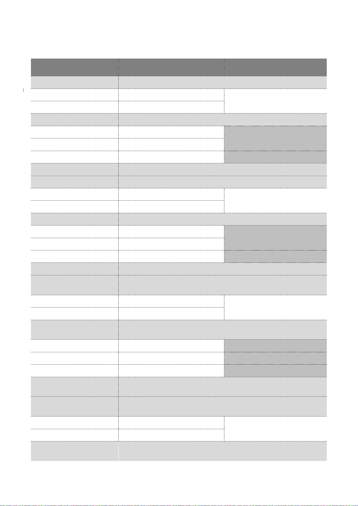
66/90
User manual SCAIME: NU-Soft-eNod4F-E-0716_235704-C.doc
13.2.8 Set points functioning
The following table describes the possible assignments.
bits
meaning
note
b0
set point 1 commutation mode
0
window
only if output 1 assigned to the ‘set
point’ function
1
hysteresis
b2 b1
set point 1 comparison measurement
00
gross
01
net
10
Sensor input control result
b3
reserved (0)
b4
set point 2 commutation mode
0
window
only if output 2 assigned to the ‘set
point’ function
1
hysteresis
b6 b5
set point 2 comparison measurement
00
gross
01
net
10
Sensor input control result
b7
reserved (0)
b8
(or b0 in CANopen®)
set point 3 commutation mode
0
window
only if output 3 assigned to the ‘set
point’ function
1
hysteresis
b10 b9
(or b2 b1 in CANopen®)
set point 3 comparison measurement
00
gross
01
net
10
Sensor input control result
b11
(or b3 in CANopen®)
reserved (0)
b12
(or b4 in CANopen®)
set point 4 commutation mode
0
window
only if output 4 assigned to the ‘set
point’ function
1
hysteresis
b14 b13
(or b6 b5 in CANopen®)
set point 4 comparison measurement
Page 67

67/90
User manual SCAIME: NU-Soft-eNod4F-E-0716_235704-C.doc
bits
meaning
note
00
gross
01
net
10
Sensor input control result
b15
(or b7 in CANopen®)
reserved (0)
13.2.9 Set points high and low values
Each set point is described by its commutation mode (hysteresis/window) and by a couple of values that are
constantly compared to the gross or net measurement or to dosing result or dosing running total (depending on the
configuration the set point has been given) in order to define the corresponding output logical level. For more details
about the set points functioning, please refer to documentation eNod4 "characteristics and functioning".
Admitted values: from -1000000 to 1000000.
Page 68

68/90
User manual SCAIME: NU-Soft-eNod4F-E-0716_235704-C.doc
13.3 Input/output level
The level of the eNod4 Input/output can be read according to the following table:
Bits
Meaning
Note
b0
0 low
IN1 level
1
high
b1
0
low
IN2 level
1
high
b2
With IO+ version only, else 0
0
low
IN3 level
1
high
b3
With IO+ version only, else 0
0
low
IN4 level
1
high
b7 ... b4
0
reserved (0)
b8 (note 1)
0
low
OUT1 level
1
high
b9 (note 1)
0
low
OUT2 level
1
high
b10 (note 1)
0
low
OUT3 level
1
high
b11 (note 1)
0
low
OUT4 level
1
high
b15 ... b12 (note 1)
0
reserved (0)
Note 1: In CANopen® communication protocol (according to version), this word is divided into 2 bytes of 8-bits
registers. Bits b8 to b15 are therefore equivalent to bits b0 to b7 of the corresponding address (see CANopen®
Register table).
Page 69

69/90
User manual SCAIME: NU-Soft-eNod4F-E-0716_235704-C.doc
14 LEGAL FOR TRADE OPTIONS
14.1 Principles
The legal for trade options are a set of functions and indicators that are generally used in weighing applications. They
have an impact on the device behavior regarding the metrological requirements and track every configuration change
that may affect the measurement determination.
14.2 Settings description
14.2.1 Legal for trade switch
This setting activates (b0 bit set to 1) or deactivates (b0 bit set to 0) criteria and parameters related to the use of
eNod4 in OIML compliance.
The ‘legal for trade’ option activation leads to the following changes:
• the ‘legal for trade counter’ is incremented every time a storage into EEPROM is requested if one or several
metrological settings have been modified.
• a new ‘legal for trade checksum’ value is calculated every time a storage into EEPROM is requested if one
or several metrological settings have been modified.
• taring is now impossible if gross measurement is negative.
• the measurement value variations cannot be read during the 15 seconds that follow the device reset (error
frame in Modbus RTU, value set to -1 in CANopen® and in Profibus DP) and during zero and tare
acquisitions
14.2.2 Legal for trade software version
This RO value identifies the version of the part of the software that is dedicated to the metrology and the
measurement exploitation.
14.2.3 Legal for trade counter
If the ‘legal for trade’ option is enabled, the legal for trade counter is incremented every time a backup into EEPROM
is requested if at least one (or several) of these settings has been modified:
• legal for trade switch
• stability criterion
• decimal point position
• maximum capacity
• number of calibration segments
Name
Modbus
address
CANopen®
Index/sub-
index
Profibus cyclic
IN/OUT
Acyclic DPV1
slot/index
Type
Access
Legal for trade
version
0x0004 LSB
0x3600 / 0x02
R : 0x0210
W: 0x0211
0x01 / 0x00
Byte
RO
Legal for trade switch
0x0004 MSB
0x3600 / 0x01
Byte
RW
Legal for trade
counter
0x0005
0x3600 / 0x03
R : 0x0212
0x01 / 0x01
Uint
RO
Legal for trade
checksum
0x0006
0x3600 / 0x04
R : 0x0214
Uint
Zero functions
0x0007
0x3501 / 0x01
R : 0x0216
W: 0x0217
0x01 / 0x02
Byte
RW
Stability criterion
0x0008 LSB
0x3605 / 0x00
R : 0x0218
W: 0x0219
0x01 / 0x03
Byte
RW
decimal point position
0x0008 MSB
0x3700 / 0x02
Byte
Weight unit
0x0009
0x3700 / 0x01
R : 0x041A
W: 0x041B
0x01 / 0x04
String
RW
Flow rate time unit
0x005A
0x3700 / 0x03
R : 0x021E
W: 0x021F
0x01 / 0x06
Uint
RW
Page 70
70/90
User manual SCAIME: NU-Soft-eNod4F-E-0716_235704-C.doc
• calibration loads 1/2/3
• scale interval
• span adjusting coefficient
• calibration place/place of use g values
• sensitivity
• A/D conversion rate
• filtering configuration (activation option, order and cut-off frequencies)
• weight unit
• flow rate time unit
• zero functions
14.2.4 Legal for trade checksum
If the ‘legal for trade’ option is enabled, a new legal for trade checksum is calculated every time a backup into
EEPROM is requested if at least one (or several) of the settings listed above has been modified.
14.2.5 Zero functions
The zero tracking and the initial zero setting can be respectively enabled by setting b0 bit or b1 bit to 1. When
activated, both options are effective on a ±10% range of the ‘maximum capacity’ (±2% if the ‘legal for trade’ option is
enabled).
14.2.6 Stability criterion
The stability criterion defines the interval on which measurements are considered as stable. Motion is indicated by b4
bit of the measurement status register. A measurement is stable if X consecutive measurements following the
reference measurement are included in the stability interval (see following table) else the current measurement
becomes the new reference measurement. X depends on the A/D conversion rate.
Bits b2 b1 b0
Stability criterion
Note
000
no motion detection (always stable)
001
0,25d
1d = 1 scale interval
010
0,5d
011
1d
100
2d
When the initial zero is used, you must use a stability criterion other than 0 to be
not affected by transient effects at power-up.
!
Page 71

71/90
User manual SCAIME: NU-Soft-eNod4F-E-0716_235704-C.doc
A/D conversion rate (meas/s)
X
50-Hz rejection
60-Hz rejection
6,25
7,5
1
12,5
15
2
25
30
3
50
60
5
100
120
9
200
240
17
400
480
33
800
960
65
1600
1920
129
14.2.7 Decimal point position
Although eNod4 measurements are integer values it is however possible to store a ‘decimal point position’ so as to
design a display related to the application. Its value represents the number of decimal digits. If the variable is set to
Zero, it means that decimal point is not used.
Decimal point position has a consistency and influences flow rate values.
Note: the decimal point is directly integrated to SCMBus protocol frames (see § SCMBus).
Admitted values: from 0 up to 7.
14.2.8 Weight unit
It is possible to store the display weight unit into the eNod4.
This weight unit is a combination of 4 characters and data has no consistency. There is no automatic calculation to
adjust flowrate values neither flowrate calibration values.
Note: the unit is directly integrated to SCMBus protocol frames (see § SCMBus).
14.2.9 Flow rate time unit
It is possible to store the display flow rate time unit into the eNod4.
Flow rate time unit is a combination of 2 characters and there is no automatic calculation to adjust flow rate value if
modified.
In loss in weight feeder mode, following values are permitted for flow rate time unit parameter:
• 0x2073 for seconds (s)
• 0x6D6E for minutes(mn)
• 0x2068 for hours (h)
In opposition to the weight unit behaviour, the flowrate unit is consistent for instant and average flowrate
determination. However and when the time unit is modified, there is no automatic redetermination of calibration
flowrate values.
14.2.10 Save Tare and Zero in non-volatile memory
There are two options for saving TARE or ZERO request value in non-volatile memory. These options are accessible
through the “dosing cycle options” Object.
Page 72

72/90
User manual SCAIME: NU-Soft-eNod4F-E-0716_235704-C.doc
15 LOSS IN WEIGHT FEEDER
15.1 Settings list
Name
Modbus
address
CANopen®
Index/sub-
index
Profibus cyclic
IN/OUT
Acyclic DPV1
slot/index
Type
Access
Instant flow rate
0x0086
0x5005 / 0x01
(M)
R : 0x0400
+ See modules
list
/
float
RO
Instant flow rate determination
time
0x0058
0x4700 / 0x01
R : 0x0274
W: 0x0275
0x07 / 0x00
Uint
RW
Instant flow rate correction factor
0x002C
0x4700 / 0x02
R : 0x0476
W: 0x0477
0x07 / 0x01
Ulong
RW
Average flow rate
0x0088
0x5005 / 0x02
(M)
R : 0x046E
+ See modules
list
/
float
RO
Nominal flow rate
0x007A
0x4706 / 0x00
R : 0x04AC
W: 0x04AD
0x07 / 0x1C
float
RW
Dosing weight deviation
0x0095
0x5007 / 0x05
(M)
R : 0x04FA
+ See modules
list
/
float
RO
Flow rate control output
0x008A
0x5005 / 0x03
(M)
R : 0x04EA
+ See modules
list
/
float
RO
Control output value
0x008C
0x5005 / 0x04
(M)
R : 0x02EC
+ See modules
list
/
Uint
RO
Refilling low level
0x0060
0x4701 / 0x05
R : 0x0482
W: 0x0483
0x07 / 0x07
Ulong
RW
Refilling high level
0x0062
0x4701 / 0x06
R : 0x0484
W: 0x0485
0x07 / 0x08
Ulong
RW
Refilling inflight value
0x0064
0x4701 / 0x07
R : 0x0486
W: 0x0487
0x07 / 0x09
long
RW
Cycle and alarm options
0x005F
0x4701 / 0x04
R : 0x0280
W: 0x0281
0x07 / 0x06
Uint
RW
Fixed flow rate during refilling
0x0066
0x4701 / 0x08
R : 0x0488
W: 0x0489
0x07 / 0x0A
float
RW
End of refill and cycle start
stabilization time
0x005E
0x4701 / 0x03
R : 0x027E
W: 0x027F
0x07 / 0x05
Uint
RW
Weight to totalize (Great WU)
0x0075
0x4705 / 0x01
R : 0x04A6
W: 0x04A7
0x07 / 0x19
Ulong
RW
Complementary weight to totalize
0x0077
0x4705 / 0x02
R : 0x02A8
W: 0x02A9
0x07 / 0x1A
Uint
RW
Weight to totalize inflight value
0x0078
0x4705 / 0x03
R : 0x04AA
W: 0x04AB
0x07 / 0x1B
long
RW
Learning cycle end of refill delay
0x005C
0x4701 / 0x01
R : 0x027A
W: 0x027B
0x07 / 0x03
Uint
RW
Learning cycle flow rates reference
determination time
0x005D
0x4701 / 0x02
R : 0x027C
W: 0x027D
0x07 / 0x04
Uint
RW
Empty hopper level
0x0068
0x4702 / 0x01
R : 0x048E
W: 0x048F
0x07 / 0x0D
Ulong
RW
Full hopper level
0x0A3E
0x4702 / 0x02
R : 0x0404
W: 0x0405
0x07 / 0x0F
Ulong
RW
Min permissible instant flow rate
0x006E
0x4704 / 0x01
R : 0x0298
W: 0x0299
0x07 / 0x12
Uint
RW
Page 73

73/90
User manual SCAIME: NU-Soft-eNod4F-E-0716_235704-C.doc
Name
Modbus
address
CANopen®
Index/sub-
index
Profibus cyclic
IN/OUT
Acyclic DPV1
slot/index
Type
Access
Max permissible instant flow rate
0x006F
0x4704 / 0x02
R : 0x029A
W: 0x029B
0x07 / 0x13
Uint
RW
Min permissible flow rate control
output
0x0070
0x4704 / 0x03
R : 0x029C
W: 0x029D
0x07 / 0x14
Uint
RW
Max permissible flow rate control
output
0x0071
0x4704 / 0x04
R : 0x029E
W: 0x029F
0x07 / 0x15
Uint
RW
Inhibit time of flow rates alarms at
start
0x0072
0x4704 / 0x05
R : 0x02A0
W: 0x02A1
0x07 / 0x16
Uint
RW
Inhibit time of flow rates alarms in
service
0x0073
0x4704 / 0x06
R : 0x02A2
W: 0x02A3
0x07 / 0x17
Uint
RW
Maximum time for refilling start
0x006B
0x4703 / 0x01
R : 0x0290
W: 0x0291
0x07 / 0x0E
Uint
RW
Time interval for weight variation
control on refilling
0x006C
0x4703 / 0x02
R : 0x0294
W: 0x0295
0x07 / 0x10
Uint
RW
Maximum refilling time
0x006D
0x4703 / 0x03
R : 0x0296
W: 0x0297
0x07 / 0x11
Uint
RW
Maximum batch time
0x0074
0x4704 / 0x07
R : 0x02A4
W: 0x02A5
0x07 / 0x18
Uint
RW
Totalizer value (Great WU)
0x008D
0x5006 / 0x01
(M)
R : 0x04F0
+ See modules
list
/
Ulong
RO
Complementary totalizer value
0x008F
0x5006 / 0x02
(M)
R : 0x02F2
+ See modules
list
/
Uint
RO
Dosing status
0x009A
0x5007 / 0x01
(M)
R : 0x02FC
+ See modules
list
/
Uint
RO
Dosing errors report
0x009B
0x5007 / 0x02
(M)
R : 0x02FE
+ See modules
list
/
Uint
RO
Dosing errors counter
0x009C
0x5007 / 0x03
(M)
R : 0x023E
+ See modules
list
/
Uint
RO
Last dosing error
0x009D
0x5007 / 0x04
(M)
R : 0x024A
+ See modules
list
/
Uint
RO
Dosing quality factor
0x009E
0x5005 / 0x05
(M)
R : 0x04EE
+ See modules
list
/
float
RO
Totalization flow rate
0x00A0
0x5006 / 0x03
(M)
R : 0x04F8
+ See modules
list
/
float
RO
Grand total (Great WU)
0x00A2
0x5006 / 0x04
(M)
R : 0x04F4
+ See modules
list
/
Ulong
RO
General total (Great WU)
0x00A4
0x5006 / 0x05
(M)
R : 0x04F6
+ See modules
list
/
Ulong
RO
Extraction time
0x00A6
0x5007 / 0x06
(M)
R : 0x0402
/
float
RO
Calibration of flow rate point 1
(control output value)
0x0A00
0x470A / 0x01
R : 0x02B4
W: 0x02B5
0x07 / 0x20
Uint
RW
Calibration of flow rate point 2
(control output value)
0x0A01
0x470A / 0x02
R : 0x02B6
W: 0x02B7
0x07 / 0x21
Uint
RW
Page 74

74/90
User manual SCAIME: NU-Soft-eNod4F-E-0716_235704-C.doc
Name
Modbus
address
CANopen®
Index/sub-
index
Profibus cyclic
IN/OUT
Acyclic DPV1
slot/index
Type
Access
Calibration of flow rate point 3
(control output value)
0x0A02
0x470A / 0x03
R : 0x02B8
W: 0x02B9
0x07 / 0x22
Uint
RW
Calibration of flow rate point 4
(control output value)
0x0A03
0x470A / 0x04
R : 0x02BA
W: 0x02BB
0x07 / 0x23
Uint
RW
Calibration of flow rate point 5
(control output value)
0x0A04
0x470A / 0x05
R : 0x02BC
W: 0x02BD
0x07 / 0x24
Uint
RW
Calibration of flow rate point 6
(control output value)
0x0A05
0x470A / 0x06
R : 0x02BE
W: 0x02BF
0x07 / 0x25
Uint
RW
Calibration of flow rate point 7
(control output value)
0x0A06
0x470A / 0x07
R : 0x02C0
W: 0x02C1
0x07 / 0x26
Uint
RW
Calibration of flow rate point 8
(control output value)
0x0A07
0x470A / 0x08
R : 0x02C2
W: 0x02C3
0x07 / 0x27
Uint
RW
Calibration of flow rate point 9
(control output value)
0x0A08
0x470A / 0x09
R : 0x02C6
W: 0x02C7
0x07 / 0x28
Uint
RW
Calibration of flow rate point 10
(control output value)
0x0A09
0x470A / 0x0A
R : 0x02C8
W: 0x02C9
0x07 / 0x29
Uint
RW
Calibration of flow rate point 1
(flow rate value)
0x0A0A
0x470B / 0x01
R : 0x04CA
W: 0x04CB
0x07 / 0x2A
float
RW
Calibration of flow rate point 2
(flow rate value)
0x0A0C
0x470B / 0x02
R : 0x04CC
W: 0x04CD
0x07 / 0x2B
float
RW
Calibration of flow rate point 3
(flow rate value)
0x0A0E
0x470B / 0x03
R : 0x04CE
W: 0x04CF
0x07 / 0x2C
float
RW
Calibration of flow rate point 4
(flow rate value)
0x0A10
0x470B / 0x04
R : 0x04D0
W: 0x04D1
0x07 / 0x2D
float
RW
Calibration of flow rate point 5
(flow rate value)
0x0A12
0x470B / 0x05
R : 0x04D2
W: 0x04D3
0x07 / 0x2E
float
RW
Calibration of flow rate point 6
(flow rate value)
0x0A14
0x470B / 0x06
R : 0x04D4
W: 0x04D5
0x07 / 0x2F
float
RW
Calibration of flow rate point 7
(flow rate value)
0x0A16
0x470B / 0x07
R : 0x04D6
W: 0x04D7
0x07 / 0x30
float
RW
Calibration of flow rate point 8
(flow rate value)
0x0A18
0x470B / 0x08
R : 0x04D8
W: 0x04D9
0x07 / 0x31
float
RW
Calibration of flow rate point 9
(flow rate value)
0x0A1A
0x470B / 0x09
R : 0x04DA
W: 0x04DB
0x07 / 0x32
float
RW
Calibration of flow rate point 10
(flow rate value)
0x0A1C
0x470B / 0x0A
R : 0x04DC
W: 0x04DD
0x07 / 0x33
float
RW
Segments number for the
calibration curve of flow rate
0x0A1E
0x4709 / 0x00
R : 0x02B2
W: 0x02B3
0x07 / 0x1F
Uint
RW
Reference flow rate control output
start refilling
0x0A31
0x4701 / 0x09
R : 0x048A
W: 0x048B
0x07 / 0x0B
float
RW
Reference flow rate control output
end refilling
0x0A33
0x4701 / 0x0A
R : 0x048C
W: 0x048D
0x07 / 0x0C
float
RW
Kp
0x0A35
0x470C / 0x01
R : 0x04DE
W: 0x04DF
0x07 / 0x34
float
RW
Ti
0x0A37
0x470C / 0x02
R : 0x04E0
W: 0x04E1
0x07 / 0x35
Ulong
RW
Td
0x0A39
0x470C / 0x03
R : 0x04E2
W: 0x04E3
0x07 / 0x36
Ulong
RW
PID behaviour
0x0A3B
0x470C / 0x04
R : 0x02E4
W: 0x02E5
0x07 / 0x37
Uint
RW
PID adjustment flow rate
0x0A3C
0x470C / 0x05
R : 0x04E6
W: 0x04E7
0x07 / 0x38
float
RW
Number of cycles for PID adjust
0x0A50
0x470C / 0x06
/
0x0B / 0x01
Uint
RW
Page 75

75/90
User manual SCAIME: NU-Soft-eNod4F-E-0716_235704-C.doc
Name
Modbus
address
CANopen®
Index/sub-
index
Profibus cyclic
IN/OUT
Acyclic DPV1
slot/index
Type
Access
Cut-off frequency of totalization
flow rate (x100)
0x0A51
0x4001/ 0x06
/
0x0B / 0x02
Uint
RW
Time unit of totalization flow rate
0x0A52
0x3700/
0x04
/
0x0B / 0x03
Uint
RW
Weight unit of totalization flow
rate
0x0A53
0x3700/
0x05
/
0x0B / 0x04
Ulong
RW
Dynamic zero acquisition time
0x005B
0x4708 / 0x00
R 0x02B0
W 0x02B1
0x07 / 0x1E
Uint
RW
15.2 Settings description
• Instant flowrate: loss in weight during a period of time expressed in weight unit per flow rate time unit.
• Instant flow rate determination time: time in seconds used for instant flow rate determination.
• Instant flow rate correction factor: correction factor coefficient expressed in 10
-6
, so 1000000 corresponds
to a correction factor coefficient of 1.00000 applied on the instant flow rate.
• Average flow rate: flow rate output of moving average filter on successive values of instant flowrate.
• Nominal flow rate: target of flow rate expressed in weight unit per flow rate time unit.
• Dosing weight deviation: weight deviation between the totalization of weight during 1 second and what
should have been totalized at nominal flowrate.
• Flow rate control output: this is the flow rate to control the extraction device, expressed in weight unit per
flow rate time unit. It can take either a fixed value of flow rate, or the output of PID controller, if enabled,
or a variable flowrate function of weight value in the hopper (or silo) during refilling phase (in smart
refilling mode).
• Control output value: control value of the analog output expressed in 0.01% of maximum output current
or voltage.
• Refilling low level: gross weight level below which a refilling has to operate if the auto refilling option is
activated, cf § refilling.
• Refilling high level: gross weight level above which a refilling has to stop when there is no refilling inflight
value.
• Refilling inflight value: refilling stops when the gross weight will reach refilling high level - refilling inflight
value.
Page 76

76/90
User manual SCAIME: NU-Soft-eNod4F-E-0716_235704-C.doc
• Cycle and alarm options: this register defines cycle and alarms functioning, cf § alarms.
See following table:
bits set to 1
Meaning
b7 … b0
Cycle options
b0
Batch dosing
b1
Clear totalization when starting a new batch cycle
b2
Auto refilling
b3
Smart refill mode
b4
Acquisition of flow rate refill references on learning cycle
b5
PID activation
b6
End of batch refill suppression
b7
Reserved (0)
b15 … b8
Alarm options
B8
Stop dosing and refilling / suspend batch on alarm
B9
Refilling to last value of flow rate
B10
Save Tare in non-volatile memory
B11
Save Zero in non-volatile memory
b15 … b12
Reserved (0)
• Fixed flow rate during refilling: flow rate fixed value used during refilling phase when the option smart
refill mode is deactivated, cf § refilling.
• End of refill stabilization time: delay in seconds that ensures that the instant flow rate has reached the
flow rate target before starting instant flow rate determination phase. This period should be the lowest
possible to reduce this volumetric phase to a minimum, cf § refilling.
• Weight to totalize (Great WU): in batch mode, the main part of batch target value in weight unit x 1000, cf
§ totalization.
• Complementary weight to totalize: in batch mode, the complementary part of batch target value in
weight unit, cf § totalization.
• Weight to totalize inflight value: in batch mode, inflight value target in weight unit to apply to the weight
to totalize, cf § totalization.
• Learning cycle end of refill delay: delay in seconds that ensures the average flow rate to be null before
activation of the extraction device. It is better to choose a long period to be sure there is no more fall of
material and also the average flow rate to be stabilized to zero before activation of the extraction device,
cf § learning cycle end of refill delay.
• Learning cycle flow rates reference determination time: time in seconds during which the flow rate
referencing is carrying out, which will be used to drive the extraction during refilling when the smart refill
mode option is activated, cf § learning cycle flow rates reference determination time.
• Empty hopper level: gross weight level under which the dosing stops and an empty hopper alarm occurs.
• Full hopper level: gross weight level over which the dosing stops and a full hopper alarm occurs (dosing
and refilling are stopped).
• Min permissible instant flow rate: low limit of flow rate value under which a flow rate alarm occurs, cf §
flow rate / control output alarms. Expressed in 0.1% of nominal flow rate.
• Max permissible instant flow rate: high limit of flow rate value over which a flow rate alarm occurs, cf §
flow rate / control output alarms. Expressed in 0.1% of nominal flow rate.
• Min permissible flow rate control output: low limit of flow rate control output value under which a flow
Page 77

77/90
User manual SCAIME: NU-Soft-eNod4F-E-0716_235704-C.doc
rate control output occurs, cf § flow rate / control output alarms. Expressed in 0.1% of nominal flow rate.
• Max permissible flow rate control output: high limit of flow rate output control value over which a flow
rate control output occurs, cf § flow rate / control output alarms. Expressed in 0.1% of nominal flow rate.
• Inhibit time of flow rates alarms at start: time throughout no flow rate alarm or flowrate control output
alarm will occur when a cycle is starting to allow dosing stabilization, cf § flow rate / control output alarms.
Expressed in seconds.
• Inhibit time of flow rates alarms in service: time throughout flow rate or flow rate control output values
should be kept outside the limit specified for an alarm to occur and after the Inhibit time of flow rates
alarms at start, cf § flow rate / control output alarms. Expressed in seconds.
• Maximum time for refilling start: maximal delay to the gross weight to be higher than its value at refilling
start. The aim is to detect no material fall when activating the refilling whether it is a manual or automatic
control (lack of material, clogging, valve or control failure), cf § refilling alarms. Expressed in seconds.
• Time interval for weight variation control on refilling: time during which a weight variation should be
positive. The aim is to detect any malfunction during the refilling phase (lack of material or clogging), cf §
refilling alarms. Expressed in seconds.
• Maximum refilling time: maximal time for the refilling phase to complete, cf § refilling alarms. Expressed in
second.
• Totalizer value (Great WU)): the main totalization result in weight unit x 1000, cf § totalization.
• Complementary totalizer value: the complementary totalization result in weight unit., cf § totalization.
• Dosing status: this register describes dosing cycle phases and additional information on the feeder
functioning. See following table:
bits set to 1
Meaning
b7 … b0
Dosing steps
b0
Stop
b1
Refilling
b2
Learning cycle end of refill delay
b3
End of refilling stabilization
b4
Flow rate determination
b5
Dosing
b6
Batch suspended
b7
Hopper emptying
b8
Reserved (0)
b15 … b9
Additional informations
b9
Learning cycle
b10
Flow rate calibrated
b11
Volumetric dosing
b12
Extraction activated
b13
Refilling in progress
b14
Dosing cycle in progress
b15
Batch complete
Page 78

78/90
User manual SCAIME: NU-Soft-eNod4F-E-0716_235704-C.doc
• Dosing errors report: this register describes exclusively the status of alarms that can occur, cf § alarms.
See coding definition in the table below:
b15 … b
0
bits set to 1
Meaning
b0
Instant flow rate > Max permissible instant flow rate
b1
Instant flow rate < Min permissible instant flow rate
b2
Flow rate control output > Max permissible flow rate control output
b3
Flow rate control output < Min permissible flow rate control output
b4
No weight variation on refilling
b5
Too long refilling time
b6
Empty hopper
b7
External totalizer output overflow
b8
Too long dosing batch time
b9
Full hopper
b15 … b10
Reserved (0)
• Dosing errors counter: this register counts the dosing errors that may occur during dosing cycles. This
counter can only be cleared by totalization / errors clear command, cf § alarms.
• Last dosing error: the last dosing error that occurs is stored in this register. Coding definition is equal to the
variable dosing errors report. This register can only be cleared by totalization / errors clear command, cf §
functional commands.
• Dosing quality factor: every second a standard deviation of the dosing weight deviation successive values
is calculated. Lower is the value, more constant is the flow rate.
• Totalization flow rate: information of flow rate that reflects the flow rate used for totalization and can be
used for external display purpose (remote display or HMI). It has its own unity and filter.
• Grand total (Great WU): high level totalization in weight unit x 1000. This totalization can be cleared
separately by the clear grand total command. The data of this totalizer is being permanently backed up
internally, cf § totalization.
• General total (Great WU): high level totalization in weight unit x 1000. This totalization can be cleared
separately by the clear general total command. The data of this totalizer is being permanently backed up
internally, cf § totalization.
• Extraction time: time measurement of extraction activation, expressed in seconds. This value is cleared
each time the extraction is activated. This parameter may be used for the evaluation of the flow rate
accuracy of the loss in weight feeder.
• Calibration of flow rate point n (control output value): expressed in 0.01% of maximum output current or
voltage. Up to 10 calibration points can be configured, see flow rate calibration, cf § flow rate calibration.
• Calibration of flow rate point n (flow rate value): expressed in weight unit per flow rate time unit. Up to
10 calibration points can be configured, see flow rate calibration, cf § flow rate calibration.
• Segments number for the calibration curve of flow rate: when the flow rate of an extraction device has a
nonlinear response in function of the flow rate output control, up to 9 segments can be configured, see
flow rate calibration, cf § flow rate calibration.
• Reference flow rate control output start refilling: reference flow rate value corresponding to the flowrate
control output that is applied at the beginning of refilling phase in smart refill mode. In this mode, the flow
rate output control value is a function of the gross weight of the hopper or silo. This parameter can be
determined automatically by a learning cycle, cf § refilling.
• Reference flow rate control output end refilling: reference flow rate value corresponding to the flowrate
control output that is applied at the end of refilling phase in smart refill mode. In this mode, the flow rate
output control value is a function of the gross weight of the hopper or silo. This parameter can be
determined automatically by a learning cycle, cf § refilling.
• Kp : proportional coefficient of the PID controller that drives the extraction device. An increase of this
Page 79

79/90
User manual SCAIME: NU-Soft-eNod4F-E-0716_235704-C.doc
parameter will degrade stability, reduce the rise time and increase the overshoot.
• T
i
: integration time constant of the PID controller that drives the extraction device, expressed in ms. An
increase of this parameter will reduce the steady state error but will degrade stability and increase time
rise and overshoot.
• Td : derivate time constant of the PID controller that drives the extraction device. Adding some derivate
can improve time rise and overshoot. The great majority of extraction devices don't accept derivate
correction or a very low value for the derivate term.
• PID behaviour: eNod4 is fitted with an automatic adjustment device of the PID parameters. Slow, Fast or
stable behaviour can be selected by the PID behaviour variable that takes 2, 1 or 0 values respectively.
• PID adjustment flow rate: flow rate value that will be used for the automatic adjustment of PID
parameters. In addition to the PID behaviour variable, the variable has to be defined previously to the PID
parameters auto-adjustment command execution.
• Number of cycles for PID adjust: It’s the number of cycles during which PID coefficients are calculated. If
this number is large, sequence will be longer but computing accuracy will be greater. We advise to fix this
number at 10.
Page 80

80/90
User manual SCAIME: NU-Soft-eNod4F-E-0716_235704-C.doc
16 REGISTERS TABLE
Chapter
Name
Modbus
address
CANopen®
Index/sub-index
Profibus
cyclic
IN/OUT
Acyclic
DPV1
slot/index
Type
Access
Protocol
Program version
0x0000
0x100A / 0x00
R : 0x021C
0x01 / 0x05
Uint
RO
Protocol
Address /
0x0001
0x2002 / 0x00
/
/
Byte
RO
Protocol
baudrate
0x2001 / 0x00
Byte
RO
Protocol
Serial number
(not managed)
0x0002
0x1018 / 0x04
/ / Ulong
RO
Metrology
Legal for trade version
0x0004
LSB
0x3600 / 0x02
R : 0x0210
W: 0x0211
0x01 / 0x00
Byte
RO
Metrology
Legal for trade switch
0x0004
MSB
0x3600 / 0x01
Byte
RW
Metrology
Legal for trade counter
0x0005
0x3600 / 0x03
R : 0x0212
0x01 / 0x01
Uint
RO
Metrology
Legal for trade checksum
0x0006
0x3600 / 0x04
R : 0x0214
Uint
Metrology
Zero functions
0x0007
0x3501 / 0x01
R : 0x0216
W: 0x0217
0x01 / 0x02
Uint
RW
Metrology
Stability criterion
0x0008
LSB
0x3605 / 0x00
R : 0x0218
W: 0x0219
0x01 / 0x03
Byte
RW
Metrology
decimal point position
0x0008
MSB
0x3700 / 0x02
Byte
Metrology
Weight unit
0x0009
0x3700 / 0x01
R : 0x041A
W: 0x041B
0x01 / 0x04
String
RW
Reserved (2 bytes)
0x000B
Calibration
Maximum capacity
0x000C
0x3002 / 0x00 (M)
R : 0x0420
W: 0x0421
0x02 / 0x00
Ulong
RW
Calibration
Number of calibration
segments
0x000E
0x3000 / 0x00
R : 0x0222
W: 0x0223
0x02 / 0x01
Uint
RW
Calibration
Calibration load 1
0x000F
0x3001 / 0x01 (M)
R : 0x0424
W: 0x0425
0x02 / 0x02
Ulong
RW
Calibration
Calibration load 2
0x0011
0x3001 / 0x02
R : 0x0426
W: 0x0427
0x02 / 0x03
Ulong
RW
Calibration
Calibration load 3
0x0013
0x3001 / 0x03
R : 0x0428
W: 0x0429
0x02 / 0x04
Ulong
RW
Calibration
Sensor sensitivity
0x0015
0x3004 / 0x00 (M)
R : 0x042A
W: 0x042B
0x02 / 0x05
Ulong
RW
Calibration
Scale interval
0x0017
0x3003 / 0x00
R : 0x022C
W: 0x022D
0x02 / 0x06
Uint
RW
Calibration
Zero calibration
0x0018
0x3005 / 0x00
R : 0x0434
W: 0x0435
0x03 / 0x04
Long
RW
Calibration
Span coefficient 1
0x001A
0x3006 / 0x04
R : 0x0436
W: 0x0437
0x03 / 0x05
Float
RW
Page 81

81/90
User manual SCAIME: NU-Soft-eNod4F-E-0716_235704-C.doc
Chapter
Name
Modbus
address
CANopen®
Index/sub-index
Profibus
cyclic
IN/OUT
Acyclic
DPV1
slot/index
Type
Access
Calibration
Span coefficient 2
0x001C
0x3006 / 0x05
R : 0x0438
W: 0x0439
0x03 / 0x06
Float
RW
Calibration
Span coefficient 3
0x001E
0x3006 / 0x06
R : 0x043A
W: 0x043B
0x03 / 0x07
Float
RW
Calibration
Span adjusting coefficient
0x0020
0x3006 / 0x01 (M)
R : 0x042E
W: 0x042F
0x03 / 0x00
Ulong
RW
Calibration
Calibration place g value
0x0022
0x3006 / 0x02
R : 0x0430
W: 0x0431
0x03 / 0x01
Ulong
RW
Calibration
Place of use g value
0x0024
0x3006 / 0x03
R : 0x0432
W: 0x0433
0x03 / 0x02
Ulong
RW
Reserved (12 bytes)
0x0026
Dosing
Instant flow rate
correction factor
0x002C
0x4700 / 0x02
R : 0x0476
W: 0x0477
0x07 / 0x01
Ulong
RW
Reserved (8 bytes)
0x002D
Inputs/outputs
External value to control
analog output (IO+
version)
0x0032
0x5050 / 0x00 (M)
R : 0x023C
W: 0x023D
+ See
modules list
0x06 / 0x0C
Uint
RW
Reserved (2 bytes)
0x0033
HMI
HMI name
0x0034
0x3701 / 0x00
/
0x0B / 0x00
String
RW
Filtering
A/D conversion rate
0x0036
0x4000 / 0x00
R : 0x0240
W: 0x0241
0x04 / 0x00
Uint
RW
Filtering
filters activation
0x0037
LSB
0x4001 / 0x01
(byte)
R : 0x0242
W: 0x0243
0x04 / 0x01
Byte
RW
Filtering
Low-pass order
0x0037
MSB
0x4001 / 0x02
(byte)
Byte
Filtering
Low-pass cut-off
frequency
0x0038
0x4001 / 0x03
R : 0x0244
W: 0x0245
0x04 / 0x02
Uint
RW
Filtering
Depth of moving average
filter on weight
0x0039
0x4001 / 0x04
R : 0x0246
W: 0x0247
0x04 / 0x03
Uint
RW
Filtering
Tolerance of clipping filter
on instant flow rates
0x003A
0x4001 / 0x05
R : 0x0248
W: 0x0249
0x04 / 0x04
Uint
RW
Reserved (6 bytes)
0x003B
Protocol and
functioning
mode
Functioning mode / Serial
protocol AUX/USB
0x003E
Functioning mode
0x2000/0x00
(byte)
R : 0x02E8
W: 0x02E9
0x07 / 0x39
Uint
RW
Reserved (2 bytes)
0x003F
Inputs/outputs
Analog output functioning
(IO+ version)
0x0040
0x4509 / 0x05
R : 0x026C
W: 0x026D
0x06 / 0x0B
Uint
RW
Page 82

82/90
User manual SCAIME: NU-Soft-eNod4F-E-0716_235704-C.doc
Chapter
Name
Modbus
address
CANopen®
Index/sub-index
Profibus
cyclic
IN/OUT
Acyclic
DPV1
slot/index
Type
Access
Inputs/outputs
Logical input 3 functioning
(IO+ version)
0x0041
LSB
0x4501 / 0x04
R : 0x026A
W: 0x026B
0x05 / 0x02
byte
RW
Inputs/outputs
Logical input 4 functioning
(IO+ version)
0x0041
MSB
0x4501 / 0x05
byte
Inputs/outputs
Logical input 1 functioning
0x0042
LSB
0x4501 / 0x02
R : 0x0250
W: 0x0251
0x05 / 0x00
byte
RW
Inputs/outputs
Logical input 2 functioning
0x0042
MSB
0x4501 / 0x03
byte
Inputs/outputs
holding time
0x0043
0x4501 / 0x01
R : 0x0252
W: 0x0253
0x05 / 0x01
Uint
RW
Inputs/outputs
Output 1 functioning
0x0044
LSB
0x4509 / 0x01
R : 0x0254
W: 0x0255
0x06 / 0x00
byte
RW
Inputs/outputs
Output 2 functioning
0x0044
MSB
0x4509 / 0x02
byte
Inputs/outputs
Output 3 functioning
0x0045
LSB
0x4509 / 0x03
R : 0x0256
W: 0x0257
0x06 / 0x01
byte
RW
Inputs/outputs
Output 4 functioning
0x0045
MSB
0x4509 / 0x04
byte
Inputs/outputs
Set point 1 high value
0x0046
0x4601 / 0x02
R : 0x025A
W: 0x025B
0x06 / 0x02
Long
RW
Inputs/outputs
Set point 1 low value
0x0048
0x4601 / 0x03
R : 0x025C
W: 0x025D
0x06 / 0x03
Long
RW
Inputs/outputs
Set point 2 high value
0x004A
0x4601 / 0x04
R : 0x025E
W: 0x025F
0x06 / 0x04
Long
RW
Inputs/outputs
Set point 2 low value
0x004C
0x4601 / 0x05
R : 0x0260
W: 0x0261
0x06 / 0x05
Long
RW
Inputs/outputs
Set point 3 high value
0x004E
0x4609 / 0x02
R : 0x0262
W: 0x0263
0x06 / 0x06
Long
RW
Inputs/outputs
Set point 3 low value
0x0050
0x4609 / 0x03
R : 0x0264
W: 0x0265
0x06 / 0x07
Long
RW
Inputs/outputs
Set point 4 high value
0x0052
0x4609 / 0x04
R : 0x0266
W: 0x0267
0x06 / 0x08
Long
RW
Inputs/outputs
Set point 4 low value
0x0054
0x4609 / 0x05
R : 0x0268
W: 0x0269
0x06 / 0x09
Long
RW
Inputs/outputs
1&2 Set points functioning
0x0056
LSB
0x4601 / 0x01
R : 0x0258
W: 0x0259
0x06 / 0x0A
byte
RW
Inputs/outputs
3&4 Set points functioning
0x0056
MSB
0x4609 / 0x01
byte
Inputs/outputs
Weight quantity per pulse
on logical output
0x0057
0x4707 / 0x00
R : 0x02AE
W: 0x02AF
0x07 / 0x1D
Uint
RW
Page 83

83/90
User manual SCAIME: NU-Soft-eNod4F-E-0716_235704-C.doc
Chapter
Name
Modbus
address
CANopen®
Index/sub-index
Profibus
cyclic
IN/OUT
Acyclic
DPV1
slot/index
Type
Access
Dosing
Instant flow rate
determination time
0x0058
0x4700 / 0x01
R : 0x0274
W: 0x0275
0x07 / 0x00
Uint
RW
Filtering
Average flow rate
determination depth
0x0059
0x4700 / 0x03
R : 0x0278
W: 0x0279
0x07 / 0x02
Uint
RW
Metrology
Flow rate time unit
0x005A
0x3700 / 0x03
R : 0x021E
W: 0x021F
0x01 / 0x06
Uint
RW
Measures
Dynamic zero acquisition
time
0x005B
0x4708 / 0x00
R 0x02B0
W 0x02B1
0x07 / 0x1E
Uint
RW
Dosing
Learning cycle end of refill
delay
0x005C
0x4701 / 0x01
R : 0x027A
W: 0x027B
0x07 / 0x03
Uint
RW
Dosing
Learning cycle flow rates
reference determination
time
0x005D
0x4701 / 0x02
R : 0x027C
W: 0x027D
0x07 / 0x04
Uint
RW
Dosing
End of refill and cycle start
stabilization time
0x005E
0x4701 / 0x03
R : 0x027E
W: 0x027F
0x07 / 0x05
Uint
RW
Dosing
Cycle and alarm options
0x005F
0x4701 / 0x04
R : 0x0280
W: 0x0281
0x07 / 0x06
Uint
RW
Dosing
Refilling low level
0x0060
0x4701 / 0x05
R : 0x0482
W: 0x0483
0x07 / 0x07
Ulong
RW
Dosing
Refilling high level
0x0062
0x4701 / 0x06
R : 0x0484
W: 0x0485
0x07 / 0x08
Ulong
RW
Dosing
Refilling inflight value
0x0064
0x4701 / 0x07
R : 0x0486
W: 0x0487
0x07 / 0x09
long
RW
Dosing
Fixed flow rate during
refilling
0x0066
0x4701 / 0x08
R : 0x0488
W: 0x0489
0x07 / 0x0A
float
RW
Dosing
Empty hopper level
0x0068
0x4702 / 0x01
R : 0x048E
W: 0x048F
0x07 / 0x0D
Ulong
RW
Reserved (2 bytes)
0x006A
Dosing
Maximum time for
refilling start
0x006B
0x4703 / 0x01
R : 0x0290
W: 0x0291
0x07 / 0x0E
Uint
RW
Dosing
Time interval for weight
variation control on
refilling
0x006C
0x4703 / 0x02
R : 0x0294
W: 0x0295
0x07 / 0x10
Uint
RW
Dosing
Maximum refilling time
0x006D
0x4703 / 0x03
R : 0x0296
W: 0x0297
0x07 / 0x11
Uint
RW
Dosing
Min permissible instant
flow rate
0x006E
0x4704 / 0x01
R : 0x0298
W: 0x0299
0x07 / 0x12
Uint
RW
Dosing
Max permissible instant
flow rate
0x006F
0x4704 / 0x02
R : 0x029A
W: 0x029B
0x07 / 0x13
Uint
RW
Dosing
Min permissible flow rate
control output
0x0070
0x4704 / 0x03
R : 0x029C
W: 0x029D
0x07 / 0x14
Uint
RW
Page 84

84/90
User manual SCAIME: NU-Soft-eNod4F-E-0716_235704-C.doc
Chapter
Name
Modbus
address
CANopen®
Index/sub-index
Profibus
cyclic
IN/OUT
Acyclic
DPV1
slot/index
Type
Access
Dosing
Max permissible flow rate
control output
0x0071
0x4704 / 0x04
R : 0x029E
W: 0x029F
0x07 / 0x15
Uint
RW
Dosing
Inhibit time of flow rates
alarms at start
0x0072
0x4704 / 0x05
R : 0x02A0
W: 0x02A1
0x07 / 0x16
Uint
RW
Dosing
Inhibit time of flow rates
alarms in service
0x0073
0x4704 / 0x06
R : 0x02A2
W: 0x02A3
0x07 / 0x17
Uint
RW
Dosing
Maximum batch time
0x0074
0x4704 / 0x07
R : 0x02A4
W: 0x02A5
0x07 / 0x18
Uint
RW
Dosing
Weight to totalize (Great
WU)
0x0075
0x4705 / 0x01
R : 0x04A6
W: 0x04A7
0x07 / 0x19
Ulong
RW
Dosing
Complementary weight to
totalize
0x0077
0x4705 / 0x02
R : 0x02A8
W: 0x02A9
0x07 / 0x1A
Uint
RW
Dosing
Weight to totalize inflight
value
0x0078
0x4705 / 0x03
R : 0x04AA
W: 0x04AB
0x07 / 0x1B
long
RW
Dosing
Nominal flow rate
0x007A
0x4706 / 0x00
R : 0x04AC
W: 0x04AD
0x07 / 0x1C
float
RW
Reserved (2 bytes)
0x007C
Measures
Measurement status
0x007D
0x5003 / 0x00 (M)
Module 1
(2 first
bytes)
/
Uint
RO
Measures
Gross measurement
0x007E
0x5001 / 0x00 (M)
Module 1
(4 last
bytes)
/
Long
RO
Measures
Tare value
0x0080
0x5004 / 0x01 (M)
R 0x0470
/
Long
RO
Measures
Net measurement
0x0082
0x5000 / 0x00 (M)
Module 2
(4 bytes
from 3rd)
/
Long
RO
Measures
Factory calibrated points
0x0084
0x5002 / 0x00 (M)
Module 2
(4 last
bytes)
/
Long
RO
Dosing
Instant flow rate
0x0086
0x5005 / 0x01 (M)
R : 0x0400
+ See
modules list
/
float
RO
Dosing
Average flow rate
0x0088
0x5005 / 0x02 (M)
R : 0x046E
+ See
modules list
/
float
RO
Dosing
Flow rate control output
0x008A
0x5005 / 0x03 (M)
R : 0x04EA
+ See
modules list
/
float
RO
Dosing
Control output value
0x008C
0x5005 / 0x04 (M)
R : 0x02EC
+ See
modules list
/
Uint
RO
Page 85

85/90
User manual SCAIME: NU-Soft-eNod4F-E-0716_235704-C.doc
Chapter
Name
Modbus
address
CANopen®
Index/sub-index
Profibus
cyclic
IN/OUT
Acyclic
DPV1
slot/index
Type
Access
Dosing
Totalizer value (Great
WU)
0x008D
0x5006 / 0x01 (M)
R : 0x04F0
+ See
modules list
/
Ulong
RO
Dosing
Complementary totalizer
value
0x008F
0x5006 / 0x02 (M)
R : 0x02F2
+ See
modules list
/
Uint
RO
Commands
Command register
0x0090
0x2003 / 0x00 (M)
Module 6
/
Uint
RW
Commands
Response register
0x0091
0x2004 / 0x00 (M)
Module 6
/
Uint
RO
Calibration
Zero offset
0x0092
0x2500 / 0x00 (M)
R : 0x0472
W: 0x0473
0x03 / 0x03
Long
RW
Inputs/outputs
Logical input level
0x0094
LSB
0x5100 / 0x00 (M)
Module 2
/
Byte
RO
Inputs/outputs
Logical ouput level
0x0094
MSB
0x5200 / 0x00 (M)
Byte
Dosing
Dosing weight deviation
0x0095
0x5007 / 0x05 (M)
R : 0x04FA
+ See
modules list
/
float
RO
Measures
Preset Tare
0x0097
0x5004 / 0x02 (M)
R : 0x04C4
W : 0x04C5
0x03 / 0x08
Ulong
RW
Reserved (2 bytes)
0x0099
Dosing
Dosing status
0x009A
0x5007 / 0x01 (M)
R : 0x02FC
+ See
modules list
/
Uint
RO
Dosing
Dosing errors report
0x009B
0x5007 / 0x02 (M)
R : 0x02FE
+ See
modules list
/
Uint
RO
Dosing
Dosing errors counter
0x009C
0x5007 / 0x03 (M)
R : 0x023E
+ See
modules list
/
Uint
RO
Dosing
Last dosing error
0x009D
0x5007 / 0x05 (M)
R : 0x024A
+ See
modules list
/
Uint
RO
Dosing
Dosing quality factor
0x009E
0x5005 / 0x04 (M)
R : 0x04EE
+ See
modules list
/
float
RO
Dosing
Totalization flow rate
0x00A0
0x5006 / 0x03 (M)
R : 0x04F8
+ See
modules list
/
float
RO
Dosing
Grand total (Great WU)
0x00A2
0x5006 / 0x04 (M)
R : 0x04F4
+ See
modules list
/
Ulong
RO
Page 86

86/90
User manual SCAIME: NU-Soft-eNod4F-E-0716_235704-C.doc
Chapter
Name
Modbus
address
CANopen®
Index/sub-index
Profibus
cyclic
IN/OUT
Acyclic
DPV1
slot/index
Type
Access
Dosing
General total (Great WU)
0x00A4
0x5006 / 0x05 (M)
R : 0x04F6
+ See
modules list
/
Ulong
RO
Dosing
Extraction time
0x00A6
0x5007 / 0x06 (M)
R : 0x0402
/
float
RO
Reserved (16 bytes)
0x00AE
**************************** SAUT TABLE D'ADRESSE MODBUS *************************************
Page 87

87/90
User manual SCAIME: NU-Soft-eNod4F-E-0716_235704-C.doc
Chapter
Name
Modbus
address
CANopen®
Index/sub-index
Profibus
cyclic
IN/OUT
Acyclic
DPV1
slot/index
Type
Access
Dosing
Calibration of flow rate
point 1 (control output
value)
0x0A00
0x470A / 0x01
R : 0x02B4
W: 0x02B5
0x07 / 0x20
Uint
RW
Dosing
Calibration of flow rate
point 2 (control output
value)
0x0A01
0x470A / 0x02
R : 0x02B6
W: 0x02B7
0x07 / 0x21
Uint
RW
Dosing
Calibration of flow rate
point 3 (control output
value)
0x0A02
0x470A / 0x03
R : 0x02B8
W: 0x02B9
0x07 / 0x22
Uint
RW
Dosing
Calibration of flow rate
point 4 (control output
value)
0x0A03
0x470A / 0x04
R : 0x02BA
W: 0x02BB
0x07 / 0x23
Uint
RW
Dosing
Calibration of flow rate
point 5 (control output
value)
0x0A04
0x470A / 0x05
R : 0x02BC
W: 0x02BD
0x07 / 0x24
Uint
RW
Dosing
Calibration of flow rate
point 6 (control output
value)
0x0A05
0x470A / 0x06
R : 0x02BE
W: 0x02BF
0x07 / 0x25
Uint
RW
Dosing
Calibration of flow rate
point 7 (control output
value)
0x0A06
0x470A / 0x07
R : 0x02C0
W: 0x02C1
0x07 / 0x26
Uint
RW
Dosing
Calibration of flow rate
point 8 (control output
value)
0x0A07
0x470A / 0x08
R : 0x02C2
W: 0x02C3
0x07 / 0x27
Uint
RW
Dosing
Calibration of flow rate
point 9 (control output
value)
0x0A08
0x470A / 0x09
R : 0x02C6
W: 0x02C7
0x07 / 0x28
Uint
RW
Dosing
Calibration of flow rate
point 10 (control output
value)
0x0A09
0x470A / 0x0A
R : 0x02C8
W: 0x02C9
0x07 / 0x29
Uint
RW
Dosing
Calibration of flow rate
point 1
(flow rate value)
0x0A0A
0x470B / 0x01
R : 0x04CA
W: 0x04CB
0x07 / 0x2A
float
RW
Dosing
Calibration of flow rate
point 2
(flow rate value)
0x0A0C
0x470B / 0x02
R : 0x04CC
W: 0x04CD
0x07 / 0x2B
float
RW
Dosing
Calibration of flow rate
point 3
(flow rate value)
0x0A0E
0x470B / 0x03
R : 0x04CE
W: 0x04CF
0x07 / 0x2C
float
RW
Dosing
Calibration of flow rate
point 4
(flow rate value)
0x0A10
0x470B / 0x04
R : 0x04D0
W: 0x04D1
0x07 / 0x2D
float
RW
Page 88

88/90
User manual SCAIME: NU-Soft-eNod4F-E-0716_235704-C.doc
Chapter
Name
Modbus
address
CANopen®
Index/sub-index
Profibus
cyclic
IN/OUT
Acyclic
DPV1
slot/index
Type
Access
Dosing
Calibration of flow rate
point 5
(flow rate value)
0x0A12
0x470B / 0x05
R : 0x04D2
W: 0x04D3
0x07 / 0x2E
float
RW
Dosing
Calibration of flow rate
point 6
(flow rate value)
0x0A14
0x470B / 0x06
R : 0x04D4
W: 0x04D5
0x07 / 0x2F
float
RW
Dosing
Calibration of flow rate
point 7
(flow rate value)
0x0A16
0x470B / 0x07
R : 0x04D6
W: 0x04D7
0x07 / 0x30
float
RW
Dosing
Calibration of flow rate
point 8
(flow rate value)
0x0A18
0x470B / 0x08
R : 0x04D8
W: 0x04D9
0x07 / 0x31
float
RW
Dosing
Calibration of flow rate
point 9
(flow rate value)
0x0A1A
0x470B / 0x09
R : 0x04DA
W: 0x04DB
0x07 / 0x32
float
RW
Dosing
Calibration of flow rate
point 10 (flow rate value)
0x0A1C
0x470B / 0x0A
R : 0x04DC
W: 0x04DD
0x07 / 0x33
float
RW
Dosing
Segments number for the
calibration curve of flow
rate
0x0A1E
0x4709 / 0x00
R : 0x02B2
W: 0x02B3
0x07 / 0x1F
Uint
RW
Reserved (36 bytes)
0x0A1F
Dosing
Reference flow rate
control output start
refilling
0x0A31
0x4701 / 0x09
R : 0x048A
W: 0x048B
0x07 / 0x0B
float
RW
Dosing
Reference flow rate
control output end
refilling
0x0A33
0x4701 / 0x0A
R : 0x048C
W: 0x048D
0x07 / 0x0C
float
RW
Dosing
Kp
0x0A35
0x470C / 0x01
R : 0x04DE
W: 0x04DF
0x07 / 0x34
float
RW
Dosing
Ti
0x0A37
0x470C / 0x02
R : 0x04E0
W: 0x04E1
0x07 / 0x35
Ulong
RW
Dosing
Td
0x0A39
0x470C / 0x03
R : 0x04E2
W: 0x04E3
0x07 / 0x36
Ulong
RW
Dosing
PID behavior
0x0A3B
0x470C / 0x04
R : 0x02E4
W: 0x02E5
0x07 / 0x37
Uint
RW
Dosing
PID adjustment flow rate
0x0A3C
0x470C / 0x05
R : 0x04E6
W: 0x04E7
0x07 / 0x38
float
RW
Dosing
Full hopper level
0x0A3E
0x4702 / 0x02
R : 0x0404
W: 0x0405
0x07 / 0x0F
Ulong
RW
Reserved (8 bytes)
0x0A40
Measures
Sensor input control
reference
0x0A44
0x5004 / 0x03 (M)
R : 0x044C
W: 0x044D
0x0A / 0x00
long
RW
Page 89

89/90
User manual SCAIME: NU-Soft-eNod4F-E-0716_235704-C.doc
Chapter
Name
Modbus
address
CANopen®
Index/sub-index
Profibus
cyclic
IN/OUT
Acyclic
DPV1
slot/index
Type
Access
Measures
Sensor input control result
0x0A46
0x5004 / 0x04 (M)
R : 0x024E
0x0A / 0x01
Int
RO
Measures
Sensor input control result
max. tolerance
0x0A47
0x5004 / 0x05
R: 0x020A
W: 0x020B
0x0A / 0x02
Uint
RW
Measures &
Inputs/
outputs
Defective measurement
debounced time
0x0A48
0x4509 / 0x06
R:0x02EC
W:0x02ED
0x06 / 0x0D
Uint
RW
Measures &
Inputs/
outputs
Defective measurement
alarm activation time
0x0A49
0x4509 / 0x07
R:0x02EE
W:0x02EF
0x06 / 0x0E
Uint
RW
Dosing
Number of cycles for
adjustment PID
0x0A50
0x470C / 0x06
/
0x0B / 0x01
Uint
RW
Measures
Cut-off frequency for
totalization flow rate
(x100)
0x0A51
0x4001 / 0x06
/
0x0B / 0x02
Uint
RW
Measures
Time unit for totalization
flow rate
0x0A52
0x3700 / 0x04
/
0x0B / 0x03
Uint
RW
Measures
Weight unit for
totalization flow rate
0x0A53
0x3700 / 0x05
/
0x0B / 0x04
Ulong
RW
Reserved (8 bytes)
0x0A4A
Page 90
90/90
User manual SCAIME: NU-Soft-eNod4F-E-0716_235704-C.doc
17 CRC-16 CALCULATION ALGORITHM
FFFFh → CRC16
CRC16 XOR octet n → CRC16
i = 0
Décalage à gauche CRC-16
carry over ?
CRC16 XOR A001h → CRC16
oui
non
i = i + 1
i = 8 ?
non
oui
n = n + 1
Fin du
message ?
non
oui
FIN
 Loading...