

Page 1

MODEL TS
ACCESSORY FOR:
STT - ALL MODELS
STC - MODELS ABOVE SERIAL NUMBER 7630001
OPERATOR’S MANUAL
THIS MANUAL CONTAINS THE OPERATING
INSTRUCTIONS AND SAFETY INFORMATION
FOR YOUR SCAG ACCESSOR Y. READING THIS
MANUAL WILL PROVIDE YOU WITH MAINTENANCE AND ADJUSTMENT PROCEDURES
TO KEEP YOUR ACCESSORY PERFORMING
TO MAXIMUM EFFICIENCY. THE SPECIFIC
MODELS THAT THIS BOOK COVERS ARE CONTAINED ON THE INSIDE COVER. BEFORE
OPERATING YOUR MACHINE, PLEASE READ
ALL THE INFORMATION ENCLOSED.
© 2004
SCAG POWER EQUIPMENT
DIVISION OF MET ALCRAFT OF MA YVILLE, INC
WWW.SCAG.COM
P ART NO. 03158
PRINTED 8-2004
PRINTED IN USA
Page 2

WARNING
FAILURE TO FOLLOW SAFE OPERATING PRACTICES
MAY RESULT IN SERIOUS INJURY.
* Keep all safety shields in place.
* Before performing any maintenance or service, stop the machine and
remove the spark plug wire.
* If a mechanism becomes clogged, stop the engine and wait for all moving
parts to come to a complete halt before cleaning.
* Keep hands, feet and clothing away from power-driven parts.
* Read this manual completely as well as the Operator's Manual that came
with your mower .
* Keep others off the tractor (only one person at a time).
REMEMBER - YOUR MOWER IS ONLY AS SAFE AS THE OPERATOR!
Hazard control and accident prevention are dependent upon the awareness,
concern, prudence, and proper training of the personnel involved in the operation, transport, maintenance, and storage of the equipment.
This manual covers the operating instructions
and illustrated parts list for:
TS with a part number of 9269
Page 3

1.1 INTRODUCTION
2.1 SAFETY INFORMATION
This manual has been prepared to provide the
information you need to correctly assemble, operate,
and maintain this Tiger Striper. Read it carefully and
keep it for future reference.
The replacement of any part on this product by other
than the manufacturer's authorized replacement part
may adversely affect the performance, durability or
safety of this product.
USE OF OTHER THAN ORIGINAL SCAG
REPLACEMENT PARTS WILL VOID THE
WARRANTY.
If additional information or service is needed that is
not outlined in this manual, please contact your Scag
Power Equipment dealer. Scag dealers are trained in
the latest service methods and carry a full line of Scag
replacement parts.
When ordering parts, always provide the complete
model of this Tiger Striper.
All information provided in this manual is based upon
information available at the time of printing. Scag
Power Equipment reserves the right to make changes
at any time without notice or obligation.
1.2 DIRECTION REFERENCE
-NOTE-
To avoid personal injury, it is imperative that all
safety instructions be observed.
1. Read this operator's manual and the
operator's manual that is supplied with the
machine this attachment is used on.
A replacement manual is available from your
authorized Scag Service Dealer or by contacting:
Scag Power Equipment, Service Department at P.O.
Box 152, Mayville, WI 53050. You may also contact
us through our website at www.scag.com. Please
indicate the complete model number of your Scag
product when ordering a replacement manual.
2. Before removing the Tiger Striper, disengage the
mower, stop the engine and wait for all
movement to stop.
3. ALWAYS turn the engine OFF, remove the key
and wait for all movement to stop before
servicing, cleaning or removing the Tiger Striper.
4. Do not modify or alter any component of the
Tiger Striper attachment or mower.
5. Do not allow any passengers to ride on the
mower.
The "Right" and "Left", "Front" and "Rear" of the
machine are referenced from the normal operating
position.
2.2 OPERATING INSTRUCTIONS
To operate the Tiger Striper, you will need to lower
the roller to the operating position. The Tiger Striper
can be easily removed or locked in the transport
position whenever the machine is being transported
or when striping is not needed.
1. To unlock the Tiger Striper from the transport
position, lift up slightly on the handle and turn the
lock pin until the small roll pin lines up with the
slot. See Figure 2-1 on page 2.
1
Page 4
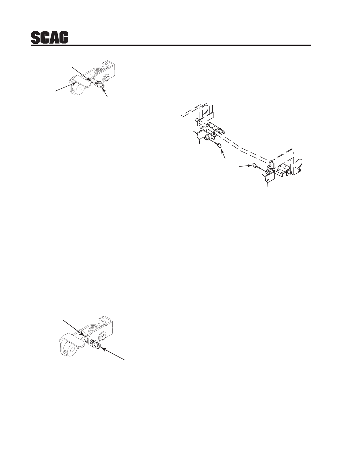
3. Repeat on opposite side.
Roll Pin
Lift Up on
Handle
Push and Turn Pin to line
up Roll Pin with Slot
to Unlock
FIGURE 2-1
2. Repeat this procedure on the opposite side.
The machine is now ready to operate.
2.3 REMOVING THE TIGER STRIPER
The Tiger Striper can be easily removed whenever
the machine is being transported or when striping is
not needed. To remove the Tiger Striper, follow the
instructions below.
1. Prepare the machine so there is easy and safe
access to the work area. Remove the key and
maintain all safety related work procedures.
Always wear eye and hand protection.
2. Lock the Tiger Striper up in the transport
position by lifting upward on the handle, push
and turn the lock pin 90 degrees. The small roll
pin must be out of the slot in the bracket to lock
in the transport position. See Figure 2-2.
Roll Pin
4. Once the Tiger Striper is locked in the transport
position, remove the quick pins securing the
Tiger Striper to the mounting brackets. See
Figure 2-3
Remove Quick Pins
FIGURE 2-3
5. Slide the Tiger Striper off of the mounting
brackets.
6. To install the Tiger Striper, slide the assembly on
to the mounting brackets and reinstall the quick
pins. Once the Tiger Striper has been reinstalled,
follow Section 2.2 Operating Instructions for
proper operation.
3.1 ASSEMBLY INSTRUCTIONS - STT
-NOTE-
Use the illustrated parts list as a part
number reference when following the
assembly instructions.
FIGURE 2-2
Push and
Turn Pin to
Lock
1. Remove all packaging materials. Lay out the
mounting hardware and the Tiger Striper
assembly for easy access.
2. Prepare the machine so there is easy and safe
access to the work area. Remove the key and
maintain all safety related work procedures.
Always wear eye and hand protection.
2
Page 5
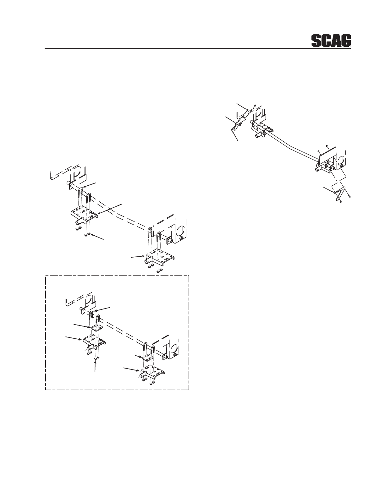
3. Attach the mounting brackets to the cross bar
between the wheel motor brackets using (4) ubolts and (8) serrated flange nuts. See Figure
3-1. Do not tighten the hardware.
5. Install the left and right hand Striper Stop
Brackets (p/n 423953 & p/n 423954) to the
frame and secure with (4) 3/8-16 x 1" bolts and
(4) elastic stop nuts. See Figure 3-2.
-NOTE-
If the Tiger Striper is installed on an STT with
a serial number below 7219999, part
number 423966 mounting spacer will need to
be installed between the mounting bracket
and cross bar. See Figure 3-1.
(4x) U-Bolts
Mounting
Bracket
(8x) Serrated Flange
Nuts
Mounting
Bracket
STT with a serial number of 7219999 or Below
(4) 3/8-16 Elastic
Stop Nut
423953 L.H.
Stop Bracket
(4) 3/8-16 x 1" Bolt
423954 R.H.
Stop Bracket
FIGURE 3-2
6. Install the Tiger Striper roller assembly to the
mounting brackets and secure with the quick
pins.
7. Once the Tiger Striper roller assembly is installed
and secure, tighten the mounting hardware on
both mounting brackets.
(4x) U-Bolts
Mounting
Spacer
Mounting
Bracket
Mounting
Spacer
Mounting
Bracket
(8x) Serrated Flange
Nuts
FIGURE 3-1
4. The edge of the mounting bracket should be
under the wheel motor mounting plate for proper
installation. See Figure 3-1.
8. Follow Section 2.2 Operating Instruction for
proper operation.
3.2 ASSEMBLY INSTRUCTIONS - STC
-NOTE-
Use the illustrated parts list as a part
number reference when following the
assembly instructions.
1. Remove all packaging materials. Lay out the
mounting hardware and the Tiger Striper
assembly for easy access.
2. Prepare the machine so there is easy and safe
access to the work area. Remove the key and
maintain all safety related work procedures.
Always wear eye and hand protection.
3
Page 6

3. Attach the mounting brackets to the cross bar
between the wheel motor brackets using (4)
u-bolts and (8) serrated flange nuts. See Figure
3-3. Do not tighten the hardware.
-Note-
The Tiger Striper cannot be installed on an
STC with a serial number below 7630001.
(4x) U-Bolts
Mounting
Spacer
Mounting
Bracket
Mounting
Spacer
(8x) Serrated Flange
Nuts
Mounting
Bracket
4.1 LAWN STRIPING
HOW DOES LAWN STRIPING WORK?
The “stripe” that you see on the lawn is actually light
reflecting off the blades of grass. The direction in
which the grass is bent determines the “light” or
“dark” stripe. When the blades of grass are bent
away from you, the grass appears lighter in color
because light is reflecting off of the length of the
blade. When the blades of grass are bent towards
you, the stripe appears darker as you are looking at
more of the tips of the blades (a smaller reflective
surface) and the shadows under the blades of grass.
Cutting a lawn in the up/down, north/south, east/
west,
opposing directions provides the best stripe
effect.
You may find that certain grasses have a more
noticeable stripe (stripe easier) than others. Cutting
the grass at a different height can sometimes change
the intensity of the stripe. A slightly higher cut
(example: 3" versus 2.5") can provide more grass to
be bent over, thus producing a more noticeable
stripe. In some types of grass, this may have the
opposite or no effect.
FIGURE 3-3
4. The edge of the mounting bracket should be
under the wheel motor mounting plate for proper
installation. See Figure 3-3.
5. Install the Tiger Striper roller assembly to the
mounting brackets and secure with the quick
pins.
6. Once the Tiger Striper roller assembly is installed
and secure, tighten the mounting hardware on
both mounting brackets.
7. Follow Section 2.2 Operating Instruction for
proper operation.
Grass that tends to be "stiff" and resists bending will
not yield a stripe as well as a softer grass that bends
easily.
Note that you do not need to cut the grass in order to
stripe it. The roller simply needs to be in the
unlocked/engaged position. You may find that when
creating more advanced, overlapping striping
patterns, you can complete the job faster by applying
the overlaying stripes without the blades engaged.
Striping can be used to draw attention to particular
landscape features. It can be used to further
enhance the finished, manicured cut that your Scag
mower delivers.
4
Page 7

LAWN STRIPING GUIDELINES
A stripe pattern can add richness and depth to any
lawn. Here are some guidelines to help produce
various patterns and to enhance your striping
techniques.
Basic stripe pattern:
Begin by mowing the perimeter around the property
(Reference Figure 4-1). Next, mow in opposing
directions through the remaining property (as shown
in Figure 4-1). Take care when turning at the end of
each row to prevent turf damage. A simple "Y"
type turn at the end of each row will reduce the
chance of turf damage while setting the mower up
for the next row to be mowed.
"Checkerboard" pattern:
Begin by mowing the perimeter around the property
(Reference Figure 4-1). Next, mow in opposing
directions (North and South or East and West)
through the remaining portion of the property (as
shown in Figure 4-1). Take care when turning at the
end of each row to prevent turf damage. A simple
"Y" type turn at the end of each row will reduce the
chance of turf damage while setting the mower up
for the next row to be mowed.
Now, travel in the opposite direction of the original
mowing pattern (if you were mowing North and
South, now mow East and West, etc). Reference
Figure 4-2.
Finish the job by mowing the perimeter again. This
will remove any stripe pattern irregularities left from
turning at the end of each row and delivers a
finished look.
FIGURE 4-1
Finish the job by mowing the perimeter again. This
will remove any stripe pattern irregularities left from
turning at the end of each row and delivers a finished
look.
FIGURE 4-2
"Diagonal or Criss-Cross" pattern:
This pattern is achieved using the same techniques as
the "Checkerboard" pattern. Simply apply the stripes in a
diagonal direction. See Figure 4-3.
FIGURE 4-3
5
Page 8
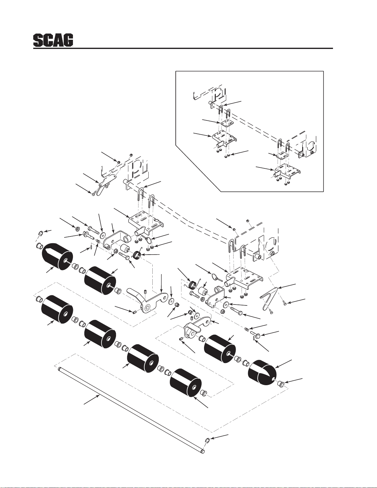
TIGER STRIPER ASSEMBLY - STT
STT with a serial number of 7219999 or Below
4 (4x)
30
5
26
27
21
27
15
30
17
25
3 (4x)
6
7
12
10
1 (4x)
2
3 (4x)
5
12
6
20
8
27
13
23
7
8
9
10
11
4 (4x)
14
31
24
6
16
18
15
1 (4x)
17
16
19
6
22
27
29
27
23
27
9
11
26
28
STT-TS Exploded View
6
Page 9

TIGER STRIPER ASSEMBLY - STT
Ref. Part
No. Number Description
1 04021-09 Nut, Elastic Stop 3/8-16
2 423953 Striper Stop, L.H.
3 04001-19 Bolt, Hex Head 3/8-16 x 1"
4 04100-01 U-Bolt, 5/16-18 x 1"
5 451660 Mounting Bracket Weldment, LH.
6 04041-11 Flatwasher, 3/8-.406 x 1-1/2" 7 Gauge
7 04001-22 Bolt, Hex Head 3/8-16 x 2-3/4"
8 04019-04 Nut, Serrated Flange 3/8-16
9 04050-02 Retaining Ring, .750 External "E"
10 461777 Pin, Lift Latch
11 04060-01 Pin, Slotted Spring .156 x 3/4"
12 482896 Spring, Lock Pin
13 04001-31 Bolt, Hex Head 3/8-16 x 2-1/2"
14 482894 Spring, Torsion L.H.
15 04019-03 Nut, Serrated Flange 5/16-18
16 04066-02 Quick Pin, .188 Dia.
17 451661 Mounting Bracket Weldment, R.H.
18 482895 Spring, Torsion R.H.
19 43648 Hub, Striper
20 451669 Pivot Weldment, L.H.
21 451670 Pivot Weldment, R.H.
22 451667 Hinge Weldment, L.H.
23 04012-06 Set Screw, 3/8-16 x 1/2"
24 04021-09 Nut, Elastic Stop 3/8-16
25 423954 Striper Stop, R.H.
26 461730 Roller Assembly, Striper End (Incl. Item 3)
27 461707 Roller Assembly (Incl. Item 28)
28 48100-24 Bushing, .752 Oilite
29 43653 Roller Shaft
30 423966 Spacer, Striper Mounting
31 451668 Hinge Weldment, R.H.
7
Page 10
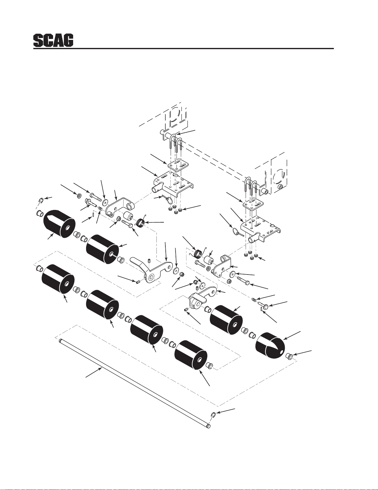
TIGER STRIPER ASSEMBLY - STC
4 (4x)
1
17
26
12
6
20
16
15
14
8
13
25
23
25
25
18
27
6
6
24
23
19
16
1
5
15
21
6
28
25
7
12
10
11
26
3
7
8
9
10
11
25
2
25
9
STC-TS Exploded View
8
Page 11

TIGER STRIPER ASSEMBLY - STC
Ref. Part
No. Number Description
1 423966 Spacer, Striper Mounting
2 43653 Roller Shaft
3 48100-24 Bushing, .752 Oilite
4 04100-01 U-Bolt, 5/16-18 x 1"
5 451660 Mounting Bracket Weldment, LH.
6 04041-11 Flatwasher, 3/8-.406 x 1-1/2" 7 Gauge
7 04001-22 Bolt, Hex Head 3/8-16 x 2-3/4"
8 04019-04 Nut, Serrated Flange 3/8-16
9 04050-02 Retaining Ring, .750 External "E"
10 461777 Pin, Lift Latch
11 04060-01 Pin, Slotted Spring .156 x 3/4"
12 482896 Spring, Lock Pin
13 04001-31 Bolt, Hex Head 3/8-16 x 2-1/2"
14 482894 Spring, Torsion L.H.
15 04019-03 Nut, Serrated Flange 5/16-18
16 04066-02 Quick Pin, .188 Dia.
17 451661 Mounting Bracket Weldment, R.H.
18 482895 Spring, Torsion R.H.
19 43648 Hub, Striper
20 451669 Pivot Weldment, L.H.
21 451670 Pivot Weldment, R.H.
22 451667 Hinge Weldment, R.H.
23 04012-06 Set Screw, 3/8-16 x 1/2"
24 04021-09 Nut, Elastic Stop 3/8-16
25 461707 Roller Assembly (Incl. Item 3)
26 461730 Roller Assembly, Striper End (Incl. Item 3)
27 451668 Hinge Weldment, L.H.
**L.H. Mounting Bracket is used on the Right Side on STC
**R.H. Mounting Bracket is used on the Left Side on STC
9
Page 12

NOTES
10
Page 13

LIMITED WARRANTY- COMMERCIAL ACCESSORY
Any part of the Scag commercial accessory manufactured by Scag and found, in the reasonable judgment of Scag,
to be defective in material or workmanship, will be repaired or replaced by an Authorized Scag Service Dealer without
charge for parts and labor.
The Scag accessory, including any defective part, must be returned to an Authorized Scag Service Dealer within
the warranty period. The expense of delivering the accessory to the dealer for warranty work and the expense of
returning it back to the owner after repair or replacement will be paid for by the owner. Scag’s responsibility in respect
to claims is limited to making the required repairs or replacements, and no claim of breach of warranty shall be cause
for cancellation or rescission of the contract of sale of any Scag machine. Proof of purchase will be required by the
dealer to substantiate any warranty claim. All warranty work must be performed by an Authorized Scag Service
Dealer.
This warranty is limited to 90 days from the date of original retail purchase for any Scag accessory that is used for
commercial purposes, or any other income-producing purpose including rental use.
This warranty does not cover any accessory that has been subject to misuse, neglect, negligence, or accident, or
that has been operated in any way contrary to the operating instructions as specified in the Operator's Manual. The
warranty does not apply to any damage to the accessory that is the result of improper maintenance, or to any
accessory or parts that have not been assembled or installed as specified in the Operator's Manual.
The warranty does not cover any accessory that has been altered or modified. In addition, the warranty does not
extend to repairs made necessary by normal wear, or by the use of parts or accessories which, in the reasonable
judgment of Scag, are either incompatible with the Scag mower or adversely affect its operation, performance or
durability. This warranty does not cover engines and electric starters, which are warranted separately by their
manufacturer.
Scag Power Equipment reserves the right to change or improve the design of any accessory without assuming any
obligation to modify any accessory previously manufactured.
All other implied warranties are limited in duration to the 90 day warranty period. Accordingly, any such implied
warranties including merchantability, fitness for a particular purpose, or otherwise, are disclaimed in their entirety
after the expiration of the appropriate ninety day warranty period. Scag’s obligation under this warranty is strictly
and exclusively limited to the repair or replacement of defective parts and Scag does not assume or authorize anyone
to assume any other obligation for them. Some states do not allow limitations on how long an implied warranty lasts,
so the above limitation may not apply to you.
Scag assumes no responsibility for incidental, consequential or other damages including, but not limited to, expense
for gasoline, oil, expense of delivering the machine to an Authorized Scag Service Dealer and expense of returning
it back to the owner, mechanic’s travel time, telephone or telegram charges, rental of a like product during the time
warranty repairs are being performed, travel, loss or damage to personal property, loss of revenue, loss of use of
the mower, loss of time, or inconvenience. Some states do not allow the exclusion or limitation of incidental or
consequential damages, so the above limitation or exclusion may not apply to you.
This warranty gives you specific legal rights, and you may also have other rights which vary from state to state.
Page 14

© 2004
SCAG POWER EQUIPMENT
DIVISION OF MET ALCRAFT OF MAYVILLE, INC
WWW.SCAG.COM
PART NO. 03158
PRINTED 8-2004
PRINTED IN USA
 Loading...