

Page 1

MODEL GC-STC-CS
OPERATOR’S MANUAL
THIS MANUAL CONT AINS THE OPERATING
INSTRUCTIONS AND SAFETY INFORMATION FOR YOUR SCAG ACCESSOR Y . READING THIS MANUAL WILL PROVIDE YOU
WITH MAINTENANCE AND ADJUSTMENT
PROCEDURES TO KEEP YOUR ACCESSORY
PERFORMING TO MAXIMUM EFFICIENCY.
THE SPECIFIC MODELS THAT THIS BOOK
COVERS ARE CONTAINED ON THE INSIDE
COVER. BEFORE OPERATING YOUR MACHINE, PLEASE READ ALL THE INFORMATION ENCLOSED.
PART NUMBER 03156
Page 2

WARNING
FAILURE TO FOLLOW SAFE OPERATING PRACTICES
MAY RESULT IN SERIOUS INJURY.
* Keep all safety shields in place.
* Before performing any maintenance or service, stop the machine and
remove the spark plug wire.
* If a mechanism becomes clogged, stop the engine and wait for all moving
parts to come to a complete halt before cleaning.
* Keep hands, feet and clothing away from power-driven parts.
* Read this manual completely as well as the Operator's Manual that came
with your mower .
* Keep others off the tractor (only one person at a time).
REMEMBER - YOUR MOWER IS ONLY AS SAFE AS THE OPERATOR!
Hazard control and accident prevention are dependent upon the awareness,
concern, prudence, and proper training of the personnel involved in the operation, transport, maintenance, and storage of the equipment.
This manual covers the operating instructions
and illustrated parts list for:
GC-STC-CS with a serial number of A8100001 to A8199999
Page 3
WARNINGWARNING
DO NOT OPERATE WITHOUT DISCHARGE CHUTE, MULCHING
KIT, OR ENTIRE GRASS CATCHER INSTALLED
DANGER
1.1 INTRODUCTION
This manual has been prepared to provide the
information you need to correctly assemble, operate,
and maintain this grass catcher. Read it carefully and
keep it for future reference.
The replacement of any part on this product by other
than the manufacturer's authorized replacement part
may adversely affect the performance, durability or
safety of this product.
USE OF OTHER THAN ORIGINAL SCAG
REPLACEMENT PARTS WILL VOID THE
WARRANTY.
If additional information or service is needed that is
not outlined in this manual, please contact your Scag
Power Equipment dealer. Scag dealers are trained in
the latest service methods and carry a full line of Scag
replacement parts.
When ordering parts, always provide the complete
model number of your catcher.
All information provided in this manual is based upon
information available at the time of printing. Scag
Power Equipment reserves the right to make changes
at any time without notice or obligation.
A replacement manual is available from your
authorized Scag Service Dealer or by contacting:
Scag Power Equipment, Service Department at P.O.
Box 152, Mayville, WI 53050. You may also contact
us through our website at www.scag.com The
manual for this grass catcher can be downloaded by
using the model and serial number or use the contact
form to make your request. Please indicate the
complete model and serial number of your Scag
product when requesting replacement manuals.
2. Before removing the grass bags, disengage the
mower, stop the engine and wait for all
movement to stop.
3. ALWAYS turn the engine OFF, remove the key
and wait for all movement to stop before
servicing or cleaning the mower or the grass
catcher.
DANGER
1.2 DIRECTION REFERENCE
The "Right" and "Left", "Front" and "Rear" of the
machine are referenced from the normal operating
position.
2.1 SAFETY AND OPERATING
INSTRUCTIONS
-NOTETo avoid personal injury, it is imperative that all
safety instructions be observed.
1. Read this operator's manual and the
operator's manual that is supplied with the
machine this attachment is used on.
ROTATING BLOWER
BLADES
STOP ENGINE BEFORE
ENTERING CHUTE
CONTACT CAN INJURE
4. Do not modify or alter any component of the
grass catcher attachment or mower.
5. Do not allow any passengers to ride on the grass
catcher attachment or on the mower.
2.2 GRASS CATCHING OPERATION
1. With the hopper door closed, engage the deck
drive.
2. Proceed to mow until the hopper is full.
1
Page 4
3. When dumping the hopper into a disposal area:
WARNING
5. To clean the hopper debris screen;
WARNING
DO NOT DUMP CLIPPINGS IN A DISPOSAL AREA THAT IS
BURNING
A. Disengage the deck drive, apply the parking
brake and allow all moving parts to come to
a complete stop.
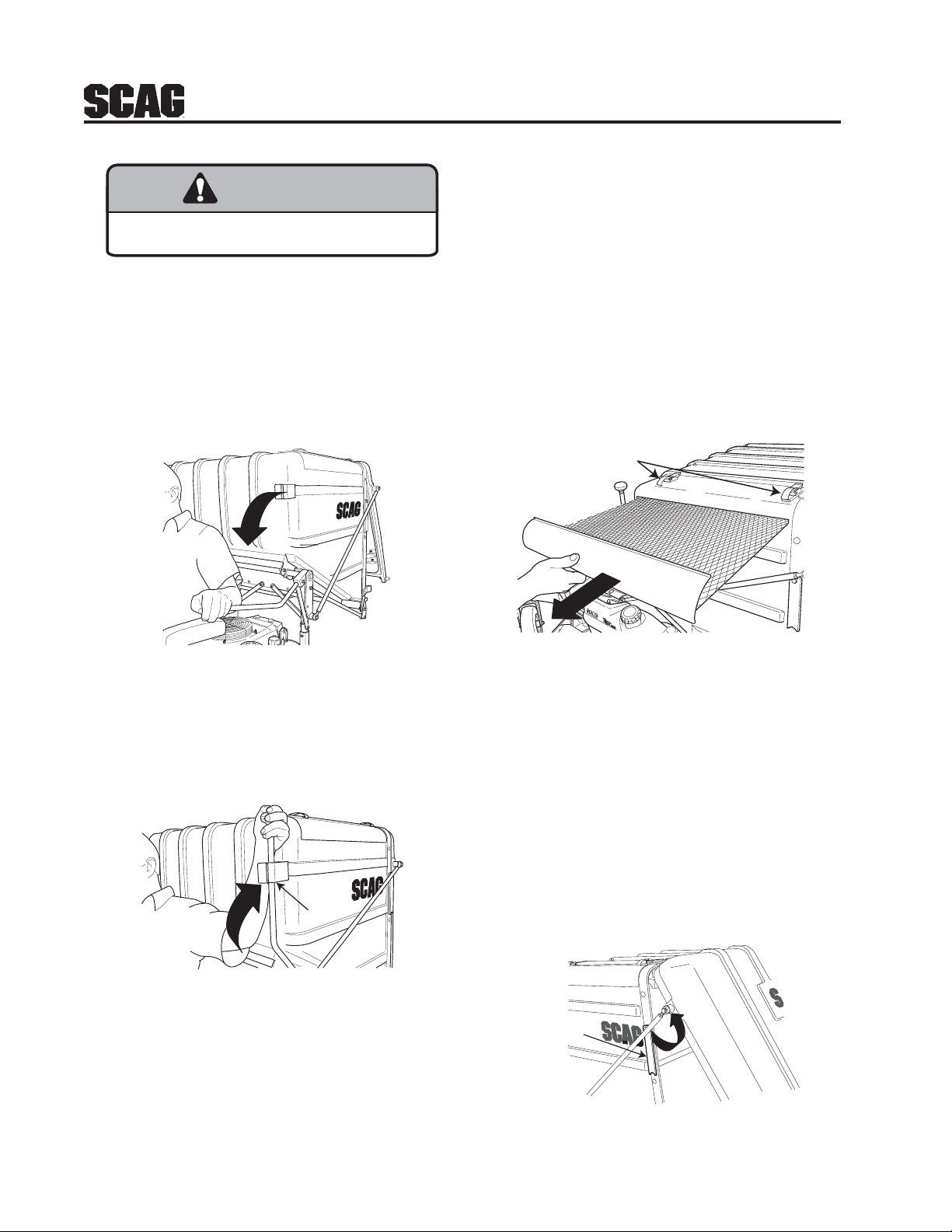
B. Pull downward on the hopper door handle to
allow the hopper sweeper to remove the
material from inside the hopper. See Figure
2-1.
Figure 2-1 GC-CS
A. Disengage the deck drive and allow all
moving parts to come to a complete stop.
B. Apply parking brake and shut off the engine.
C. Stand on the left side of the hopper
assembly.
D. Unhook the debris screen latches and
remove the debris screen from the hopper.
See Figure 2-3.
Debris Screen
Latches
Figure 2-3 GC-CS
FIGURE 2-1
C. Once the material has been completely
removed from the hopper, lift the hopper
door handle to close the hopper door and
lock into place. See Figure 2-2.
LOCK
Figure 2-2 GC-CS
FIGURE 2-2
4. When dumping the hopper into a disposal area,
inspect the hopper debris screen for material.
When the debris screen is full of material, the
grass catching ability may suffer. Frequency of
cleaning the hopper debris screen will vary
depending on conditions.
FIGURE 2-3
E. Remove material from the debris screen and
reinstall. Secure by latching the debris
screen latches.
6. When service is needed inside the hopper,
disengage the deck drive and allow all moving
parts to come to a complete stop, shut off the
engine and apply the parking brake. Rotate the
hopper door prop rod upward until it contacts the
hopper door. This will prevent the hopper door
from moving until the service is complete. See
Figure 2-4.
Hopper Prop
Rod
Figure 2-4 GC-CS
FIGURE 2-4
2
Page 5
3.1 ASSEMBLY INSTRUCTIONS FOR 48"
WARNING
AND 52" CUTTER DECK
-NOTEUse the illustrated parts list as a part number
reference when following the assembly
instructions.
-NOTEWhen installing this grass catcher on a machine
with a serial number range from 7630001 to
8479999, you will need to install part number
461764 for a 48" cutter deck or 461765 for a
52" cutter deck. This kit includes a new Turbo
Baffle and Deck Baffle.
1. Remove all packaging materials. Lay out the
mounting hardware and the catcher assembly
parts for easy access. Prepare the work area
making sure that it is a clean, safe environment.
WARNING
DO NOT OPERATE WITHOUT DISCHARGE CHUTE, MULCHING
KIT, OR ENTIRE GRASS CATCHER INSTALLED
2. Remove the discharge chute from the cutter
deck. See Figure 3-1.
-NOTEDo not discard the discharge chute or
mounting hardware. The discharge chute
MUST be reinstalled anytime the grass
catcher is removed from the machine.
3. Remove the right side belt cover to gain access to
the spindle assembly. Remove the front u-nut
from the cutter deck bracket. See Figure 3-1.
4. Install the grass catcher pulley onto the spindle
assembly. Apply loctite to both pulley setscrews
and tighten. See Figure 3-1.
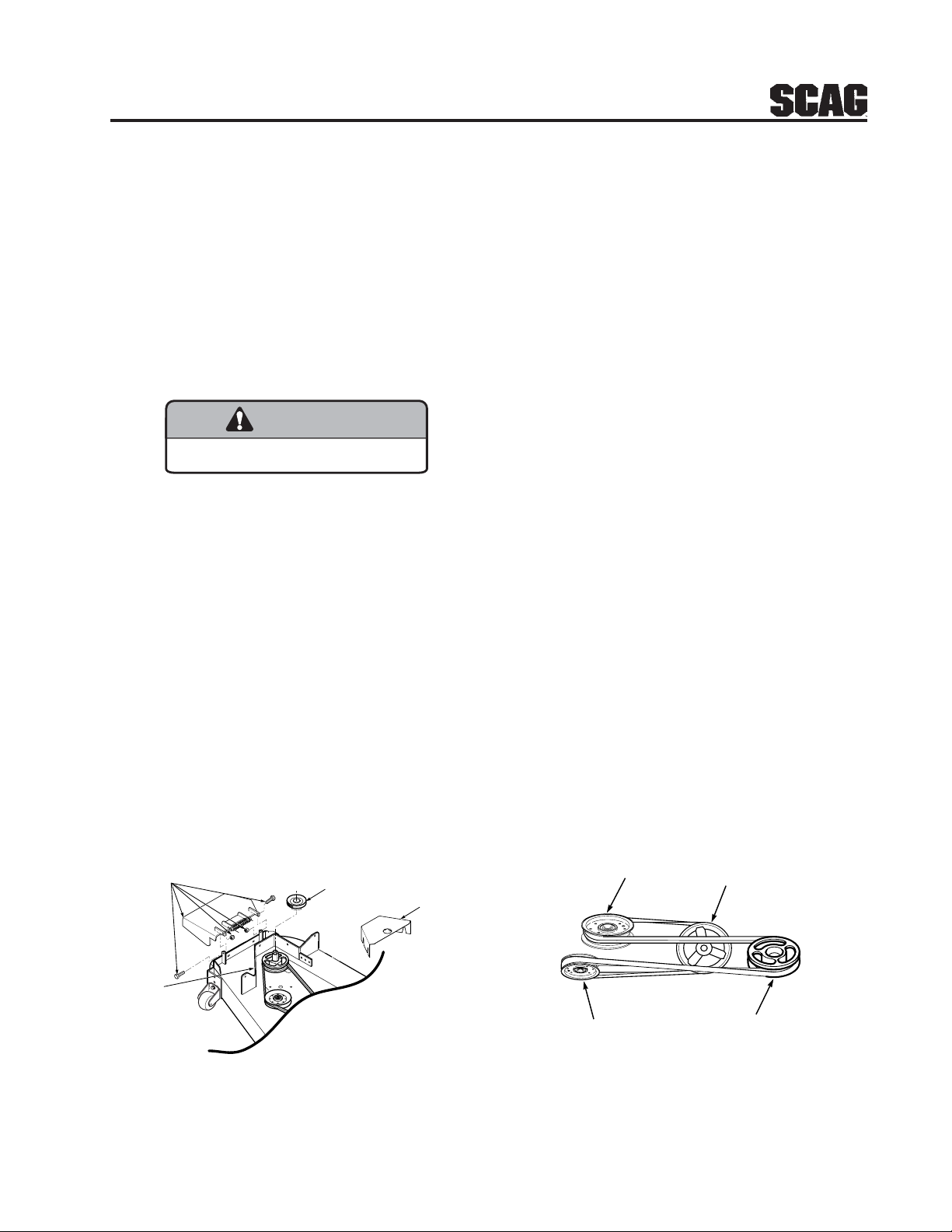
5. Install the blower mounting bracket to the deck
using carriage bolts (p/n 04003-11), lockwashers,
and nuts. Do not fully tighten the hardware at
this time. See Figure 3-2, Page 4.
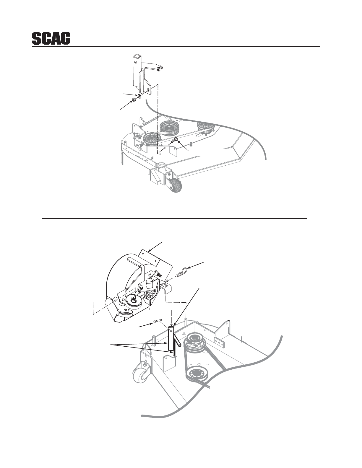
6. Install the blower assembly to the mounting
bracket and secure with the mounting pin.
See Figure 3-3, Page 4.
7. Align the blower assembly with the discharge
opening of the cutter deck. Tighten the hardware
for the mounting bracket. Then tighten the
hardware for the catch plate. See Figure 3-3,
Page 4.
8. Install the large hair pin through the rear hole in
the discharge chute mounting bracket. See
Figure 3-3, Page 4.
Retain the original belt cover. This cover
MUST be reinstalled anytime the
complete catcher system is removed.
REMOVE DISCHARGE
CHUTE AND
HARDWARE
REMOVE U-NUT
-NOTE-
INSTALL PULLEY
ON RH SPINDLE SHAFT ON TOP OF EXISTING
SPINDLE DRIVE
PULLEY
RIGHT SIDE OF
CUTTER DECK SHOWN
(Note: Some parts not shown for viewing purposes.)
FIGURE 3-1
REMOVE EXISTING
RT. SIDE BELT
COVER
Figure 1- GC-STC install art
9. Install the belt to the spindle pulley. When
replacing the belt, see figure below.
BACK SIDE
IDLER PULLEY
FRONT SIDE
IDLER PULLEY
BLOWER
PULLEY
SPINDLE
PULLEY
3
Page 6
FLATWASHER
ELASTIC STOP
NUT
CARRIAGE BOLT
FIGURE 3-2
BLOWER
ASSEMBLY
HAIR
PIN
TIGHTEN
CATCH PLATE
HARDWARE
MOUNTING PIN
TIGHTEN MOUNTING
BRACKET HARDWARE
2005 GC-STC install art 3
PROPERLY
SERVICE
ENGINE
WITH
OIL
AND
FUEL.
FIGURE 3-3
4
MOUNTING
BRACKET
RIGHT SIDE OF
CUTTER DECK SHOWN
(Note: Some parts not shown for viewing purposes.)
Page 7

10. Install the new belt covers and secure. See
items number 1 and number 21 on page 10 of the
Blower Mounting Components section in the
Illustrated Parts List for proper installation.
11. Install the hopper mounting brackets to the
outside of the frame on the rear of the machine.
See Figure 3-4.
Hopper
Mounting
Brackets
-NOTEThe hopper dump handle can be installed on
either side for operator convenience. When
installing this grass catcher on a machine
with the Roll Over Protection System (ROPS),
the curved handle will need to be installed on
the right side.
13. Install the hose from the blower assembly
adapter to the hopper hood and secure using the
6-1/2" clamps.
Rear Frame
Figure 4 A GC-STT Install Art
FIGURE 3-4
12. With help from an assistant, install the hopper
assembly to the machine by installing the
mounting post into the hopper mounting brackets
and secure with the ring pins. Tighten the bolts
and jam nuts. See Figure 3-5.
14. Using the weight support bar as a guide, identify
the four corresponding mounting holes, and the
existing hardware that will need to be removed
in order to secure the weight support bar to the
front of the machine as shown. See Figure 3-6.
15. Install one 7/16-14 x 1-3/4" hex head bolt into
each of the four mounting holes in the weight
support bar, and through the matching holes in
the caster support weldment. Secure this
assembly to the front of the machine using the
7/16- .5" x 1-1/4" x .083" flatwashers, and the
7/16-14 elastic stop nuts. Torque hardware to
59 ft. lbs. See Figure 3-6.
Locking
Bolts
FIGURE 3-6
16. Operate and test.
Locking
Bolts
Ring Pins
Ring Pins
FIGURE 3-5
5
Page 8

4.1 GRASS CATCHER REMOVAL
WARNING
INSTRUCTIONS
1. Prepare the work area making sure that it is a
clean, safe environment.
2. Remove the rubber strap holding the adapter to
the blower assembly. See Figure 4-1.
3. Remove the pin and hair pin holding the blower
assembly to the mounting bracket on the cutter
deck and remove the blower assembly. See
Figure 4-1.
ADAPTER
HAIR
BLOWER
ASSEMBLY
2004 GC-STC removal art 1
PIN
MOUNTING
BRACKET
PIN
RIGHT SIDE OF
CUTTER DECK SHOWN
(Note: Some parts not shown for viewing purposes.)
5. With help from an assistant, remove the hopper
assembly from the mounting posts.
WARNING
DO NOT OPERATE WITHOUT DISCHARGE CHUTE, MULCHING
KIT, OR ENTIRE GRASS CATCHER INSTALLED
6. Re-install the side discharge chute to the opening
on the cutter deck. Replace the two outside
mounting bolts on the discharge chute with the
clevis pins (p/n 04064-15) and rue cotter pins
(p/n 04069-03). See Figure 4-3.
DISCHARGE
CHUTE
CLEVIS PIN
P/N 04064-15
GC-STC removal art 3
FIGURE 4-3
CLEVIS PIN
P/N 04064-15
RUE COTTER PIN
P/N 04069-03
FIGURE 4-1
4. Loosen the four (4) locking bolts and jam nuts.
Remove the two (2) pins holding the hopper
assembly to the mounting posts on the rear of the
machine. See Figure 4-2.
Loosen
Loosen
Locking
Bolts
Locking
Bolts
Remove
Mounting
Pins
2005 GC-STC removal art 2-A
Remove
Mounting
Pins
FIGURE 4-2
6
Page 9

Notes
7
Page 10

GC-STC 48" & 52" BLOWER HOUSING ASSEMBLY
DANGER
DANGER
39
48
10
9
11
12
13
4
5
6
8
7
10
9
11
14
47
14
15
11
12
27
44
1
2
3
10
43
16
21
15
14
17
34
42
41
40
41
27
26
17
IN
S
T
A
W
O
L
P
L
A
R
E
B
E
R
A
R
E
D
A
O
L
N
T
P
T
E
IN
R
IN
C
A
G
T
O
O
R
V
M
G
'
S
E
A
M
R
C
A
N
B
H
U
A
IN
E
L
F
E
O
R
E
18
19
25
28
20
38
22
23
46
35
51
3
27
24
14
R
D
O
T
A
A
N
T
Stop eng
I
N
G
G
E
B
ine be
L
R
DO
U
A
D
N
N
ISC
D
LE
fore cleaning or rem
O
E
H
T O
SS
A
S
G
R
P
GE
ER
A
R
E
G
N
R
E
W
A
O
L
D
B
G
N
I
T
A
T
O
R
S
E
D
A
L
B
E
R
O
F
E
B
E
IN
G
N
E
P
E
T
O
T
U
H
S
C
G
N
I
R
E
T
N
E
E
R
U
J
IN
N
A
C
T
C
A
T
N
O
C
R
E
W
O
L
B
S
G
E
E
N
R
I
D
T
O
A
A
F
L
T
E
E
B
O
B
T
R
U
E
H
N
I
E
C
G
DANGER
R
G
N
U
E
N
J
I
N
P
R
I
E
O
N
T
T
A
S
N
C
E
T
C
A
T
N
O
C
R
A
N
G
ATE
S
S
UA
D
C
M
R
B
A
D
O
TC
L
IS
W
H
O
ER
o
IN
E
vin
W
R O
S
g
TA
E
R
L
R
L
ED
29
24
14
50
30
33
37
31
32
31
45
47
2005 GC Blower Assembly
35
34
45
49
8
Page 11

GC-STC 48" & 52" BLOWER HOUSING ASSEMBLY
Ref. Part
No. Number Description
1 04067-07 Pin, Ring 2-1/4" Long
2 481547 Lanyard, Deck Height Pin
3 04019-02 Nut, Serr. Flange 1/4-20
4 04001-59 Bolt, Hex Head 1/4-20 x 1-1/4"
5 04001-01 Bolt, Hex Head 1/4-20 x 3/4"
6 423298 Belt Cover, Rear
7 481428 Grip, Blower Lever
8 482300 Cap, Square
9 04024-02 Nut, Push On 3/8 Thread
10 04021-05 Lock Nut, 3/8-16
11 04041-07 Flatwasher, 3/8-.391 x .938 x .105
12 43277 Spacer
13 482299 Pulley, Idler 4" Dia.
14 04021-09 Nut, Elastic Stop 3/8-16
15 04030-04 Lockwasher, 3/8-16
16 423933 Plate, Catch Mounting
17 04003-05 Bolt, Carr. 3/8-16 x 1-1/2"
18 04001-54 Bolt, Hex Head 3/8-16 x 3" - 52"
04001-46 Bolt, Hex Head 3/8-16 x 2-1/4" - 61"
19 04001-81 Bolt, Hex Head 3/8-16 x 3-1/2"
20 04001-21 Bolt, Hex Head 3/8-16 x 1-3/4"
21 461812 Idler Arm Assembly
22 482278 Belt, GC-STC
23 482079 Pulley, 3" O .D., GC-STC
24 04043-04 Washer, 3/8 Hardened
25 43575 Pivot, Idler
26 481039 Decal, Belt Cover
Ref. Part
No. Number Description
27 04019-04 Nut, Serr. Flange 3/8-16
28 04001-136 Bolt, Hex Head 3/8-16 x 1-1/2 Gr. 8
29 481377 Decal, Danger
30 461681 Blower Housing Assembly
31 04003-12 Bolt, Carr. 5/16-18 x 3/4" Gr . 5
32 04063-06 Key, 1/4 x 1/4 x 1-1/2"
33 451683 Fan Weldment
34 483034 Bearing Assembly
35 04021-10 Nut, Elastic Stop 5/16-18
36 04040-04 Flatwasher, 5/16-.344 x .688 x .065
37 421319 Cover, Blower Housing
38 48136-02 Clamp, 8-5/8" Max Dia.
39 48135-09 Hose, 8.00" Dia. x 53" Long
40 482298 Pulley, 4-3/4" O.D. - 1" Bore
41 04012-04 Set Screw, 5/16-18 x 3/8"
42 451655 Frame, Blower Mount
43 481522 Spring, Main Drive
44 43212 Spacer
45 04019-03 Nut, Serr. Flange 5/16-18
46 461723 Adapter w/Strap
47 424094 Plate, Blower Catch
48 04062-05 Hair Pin Cotter, .243 x 4"
49 461680 Blower Housing Assembly, GC-STT
50 482080 Decal, Rotating Blower
51 481377 Decal, Blower
9
Page 12

GC-STC 48" & 52" BLOWER MOUNTING COMPONENTS
FOR MACHINES WITH A SERIAL
NUMBER BETWEEN
7630001 - 8479999
ONLY
30
10
6
10
2
4
1
3
12
5
13
11
6
7
8
6
9
21
23
25
26
28
32
27
29
27
29
28
UNDER SIDE OF
CUTTER DECK SHOWN
31
24
25
26
16
20
18
17
22
14
15
15
19
RIGHT SIDE OF
CUTTER DECK SHOWN
10
390STC203B
Page 13

GC-STC 48" & 52" BLOWER MOUNTING COMPONENTS
Ref. Part
No. Number Description
1 482612 Belt Cover, GC-STC
2 04029-04 Wingnut, Plastic 3/8" Small
3 482300 Cap, Square Vinyl
4 04021-08 Nut, Elastic Stop 1/4-20
5 461723 Adapter, Blower GC-STC, includes item #7
6 04040-14 Flatwasher, 1/4-.312 x .750 x .065
7 48137-04 Rubber Strap 7-3/4"
8 04001-59 Bolt, Hex Head 1/4-20 x 1-1/4"
9 481625-01 Knob W/Stud, 3/8-16 x 1-1/4"
10 04064-15 Clevis Pin, 5/16 x 1-1/2"
11 04069-03 Pin, Rue Cotter 5/16 Dia.
12 04067-07 Pin, Ring 1/2 x 2-1/4"
13 481547 Lanyard
14 482587 Pulley, 4.0" Dia. 1.125 Bore
15 04012-04 Setscrew, 5/16-18 x 3/8"
16 04021-09 Nut, Elastic Stop 3/8-16
17 04030-04 Lockwasher, 3/8"
18 04041-07 Flatwasher, 3/8-.391 x .938 x .105
19 04003-11 Bolt, Carr. 3/8-16 x 1-1/4" Grade 5
20 451693 Mounting Post Weldment, Blower
21 423708 Belt Cover
22 04110-03 U-Nut
23 04017-05 Bolt, Hex Head 1/4-20 x 3/4"
24 04003-23 Bolt, Carriage 3/8-16 x 1"
25 04021-09 Nut, Elastic Stop 3/8-16
26 04041-07 Flatwasher, 3/8-.391 x .938 x .105
27 04001-09 Bolt, Hex Head 5/16-18 x 1"
28 04040-15 Flatwasher, 5/16-.375 x .875 x .083
29 04021-10 Nut, Elastic Stop 5/16-18
30 04019-02 Nut, Serrated Flange 1/4-20
31 423633 Baffle, 48"
423629 Baffle, 52"
32 423955 Baffle, Turbo 48" Deck
423956 Baffle, Turbo 52" Deck
11
Page 14

16
GC-STC-CS HOPPER COMPONENTS
14
49
50
6
55
2
53
34
12
34
55
6
18
33
24
40
45
58
58
56
10
54
53
59
59
49
43
49
49
28
15
49
49
29
61
25
49
62
50
53
52
36
41
60
A
35
61
20
19
53
46
5
33
37
36
49
66
65
64
21
37
57
C
26
49
60
49
4
10
61
60
C
33
32
38
46
28
27
43
38
13
58
3
31
29
48
53
7
B
59
45
41
11
37
25
49
46
A
51
44
68
58
46
26
40
59
34
42
63
49
30
22
49
49
17
8
12
9
34
50
B
24
49
18
49
70
1
38
19
63
33
65
20
61
69
71
71A
49
53
38
53
57
64
66
49
21
67
35
33
45
49
65
49
23
32
37
60
2005 CSHOPPEREXPLOD-STC
12
Page 15

GC-STC-CS HOPPER COMPONENTS
Ref. Part
No. Number Description
1 461627 Hopper, GC-STC-CS
2 482732 Door, GC-CS
3 461626 Sweeper Weldment, GC-CS
4 482777 Pad, Rubber
5 04090-02 Pop Rivet, 3/16 x .652
6 423834 Plate, Stiffener
7 423938 Support Frame, Hopper
8 423849 Hinge Bracket, L.H.
9 423850 Hinge Bracket, R.H.
10 423858 Bracket, Hopper Support
11 423837 Latch, Door Prop
12 423840 Plate, Latch
13 451599 Bellcrank Weldment, Upper
14 451601 Debris Screen Weldment
15 451602 Screen Support Weldment, Rear
16 451603 Screen Support Weldment, Front
17 451607 Hinge Weldment, Hopper
18 43631 Spacer
19 423851 Brace Stiff ener, Short
20 423852 Tube, Upright
21 422386 Brace, Engine Mount
22 423862 Latch, Dump Rod Inner
23 423864 Latch, Dump Rod Outer
24 43063 Spacer
25 43282 Spacer
26 43277 Spacer
27 481309 Latch, Hood
28 43641 Linkage Assembly, Lower
29 43640 Linkage Assembly, Upper
30 481245 Knob
31 04001-10 Bolt, Hex Head 5/16-18 x 1-1/4
32 04001-18 Bolt, Hex Head 3/8-16 x 3/4"
33 04001-19 Bolt, Hex Head 3/8-16 x 1"
34 04001-20 Bolt, Hex Head 3/8-16 x 1-1/2"
35 04001-21 Bolt, Hex Head 3/8-16 x 1-3/4"
36 04001-32 Bolt, Hex Head 3/8-16 x 1-1/4"
37 04001-45 Bolt, Hex Head 3/8-16 x 2"
38 04001-46 Bolt, Hex Head 3/8-16 x 2-1/4"
39 04001-63 Bolt, Hex Head 5/16-18 x 3-1/2"
Ref. Part
No. Number Description
40 04001-77 Bolt, Hex Head 3/8-16 x 3-1/2"
41 04003-04 Bolt, Carriage 5/16-18 x 1"
42 04010-01 Screw, #10-32 x 1/2"
43 04017-16 Cap Screw, 5/16-18 x 3/4" Serr. Flan.
44 04017-17 Cap Screw, 5/16-18 x 1" Serr. Flan.
45 04019-03 Nut, 5/16-18 Serrated Flange
46 04019-04 Nut, 3/8-16 Serrated Flange
47 04020-12 Nut, 3/8-16 UNC Jam
48 04021-01 Nut, #10-32 Elastic Stop
49 04021-09 Nut, 3/8-16 Elastic Stop
50 04021-10 Nut, 5/16-18 Elastic Stop
51 04032-01 Washer, Special Wave
52 04040-15 Washer, 5/16-.375 x .875 x .083 Flat
53 04041-07 Washer, 3/8-.931 x .938 x .105 Flat
54 43642 Bushing, Hopper Latch GC-CS
55 04001-54 Bolt, Hex Head 3/8-16 x 3"
56 451598 Hinge Weldment, Door
57 481547 Lanyard
58 481538 Rod End Male, 3/8-24 L.H. Thread
59 04020-26 Nut, 3/8-24 UNF L.H. Thread
60 481539 Rod End Male, 3/8-24 R.H. Thread
61 04020-25 Nut, 3/8-24 UNF R.H. Thread
62 423865 Alignment Bracket, GC-CS
63 04001-31 Bolt, Hex Head 3/8-16 x 2-1/2"
64 04030-04 Lock Wasker, 3/8-16 Spring
65 04020-04 Nut, 3/8-16 UNC Zinc
66 04021-05 Nut, 3/8-16 Center Lock
67 04001-12 Bolt, Hex Head 5/16-18 1-3/4"
04012-10 Nut, 5/16-18 Elastic Stop (Not Shown)
68 44147 Rod, Dump Lever
69 423855 Bracket, Lower Stiffener
423859 Backing Plate, Hopper (Not Shown)
70 423836 Retainer Strip, Hopper
71 451726 Mounting Bracket Weldment, R.H.
71A 451725 Mounting Bracket Weldment, L.H.
13
Page 16

481039
GC-STC-CS DECALS
482275
481327
483037
481377
14
483039
Page 17

LIMITED WARRANTY- COMMERCIAL ACCESSORY
Any part of the Scag commercial accessory manufactured by Scag and found, in the reasonable judgment of Scag,
to be defective in material or workmanship, will be repaired or replaced by an Authorized Scag Service Dealer without
charge for parts and labor.
The Scag accessory, including any defective part, must be returned to an Authorized Scag Service Dealer within
the warranty period. The expense of delivering the accessory to the dealer for warranty work and the expense of
returning it back to the owner after repair or replacement will be paid for by the owner. Scag’s responsibility in respect
to claims is limited to making the required repairs or replacements, and no claim of breach of warranty shall be cause
for cancellation or rescission of the contract of sale of any Scag machine. Proof of purchase will be required by the
dealer to substantiate any warranty claim. All warranty work must be performed by an Authorized Scag Service
Dealer.
This warranty is limited to 90 days from the date of original retail purchase for any Scag accessory that is used for
commercial purposes, or any other income-producing purpose including rental use.
This warranty does not cover any accessory that has been subject to misuse, neglect, negligence, or accident, or
that has been operated in any way contrary to the operating instructions as specified in the Operator's Manual. The
warranty does not apply to any damage to the accessory that is the result of improper maintenance, or to any
accessory or parts that have not been assembled or installed as specified in the Operator's Manual.
The warranty does not cover any accessory that has been altered or modified. In addition, the warranty does not
extend to repairs made necessary by normal wear, or by the use of parts or accessories which, in the reasonable
judgment of Scag, are either incompatible with the Scag mower or adversely affect its operation, performance or
durability. This warranty does not cover engines and electric starters, which are warranted separately by their
manufacturer.
Scag Power Equipment reserves the right to change or improve the design of any accessory without assuming any
obligation to modify any accessory previously manufactured.
All other implied warranties are limited in duration to the 90 day warranty period. Accordingly, any such implied
warranties including merchantability, fitness for a particular purpose, or otherwise, are disclaimed in their entirety
after the expiration of the appropriate ninety day warranty period. Scag’s obligation under this warranty is strictly
and exclusively limited to the repair or replacement of defective parts and Scag does not assume or authorize anyone
to assume any other obligation for them. Some states do not allow limitations on how long an implied warranty lasts,
so the above limitation may not apply to you.
Scag assumes no responsibility for incidental, consequential or other damages including, but not limited to, expense
for gasoline, oil, expense of delivering the machine to an Authorized Scag Service Dealer and expense of returning
it back to the owner, mechanic’s travel time, telephone or telegram charges, rental of a like product during the time
warranty repairs are being performed, travel, loss or damage to personal property, loss of revenue, loss of use of
the mower, loss of time, or inconvenience. Some states do not allow the exclusion or limitation of incidental or
consequential damages, so the above limitation or exclusion may not apply to you.
This warranty gives you specific legal rights, and you may also have other rights which vary from state to state.
Page 18

© 2004
SCAG POWER EQUIPMENT
DIVISION OF MET ALCRAFT OF MAYVILLE, INC
www.scag.com
PART NO. 03156
PRINTED 8-2004
PRINTED IN USA
 Loading...