

SBS AT10.1 series Operating And Service Instructions

Operating and Service Instructions
AT10.1 SERIES
MICROPROCESSOR-CONTROLLED
FLOAT BATTERY CHARGER
SINGLE PHASE INPUT
GROUP II
(30 - 100 Adc OUTPUT)
Address: N56 W16665 Ridgewood Drive
Menomonee Falls, WI 53051
Tel: 800-554-2243
Fax: 262-703-3073
Online: www.SBSBattery.com

HOW TO REA D THE AT10.1 MODEL NUMBER
GROUP II RATINGS (30-100 Adc)
The AT10.1 configured model number is coded to describe the unit's features and options. Please
identify the model number printed on the data nameplate decal, and write it in the spaces provided below.
AT10
A B C D E F G H J K L M N P
Follow the chart below to determine the configuration of the AT10.1.
DESCRIPTION CODE FEATURE DESCRIPTION CODE FEATURE
A SERIES AT10 AT10.1 BATTERY CHARGER S STANDARD
NOMINAL
DC OUTPUT
B
VOLTAGE
NOMINAL
C
DC OUTPUT
CURRENT
F SUPPLIED
DC OUTPUT
D
FILTERING
AC INPUT
E
VOLTAGE
DESCRIPTION CODE FEATURE DESCRIPTION CODE FEATURE
012 12 Vdc M MEDIUM A IC
024 24 Vdc H HIGH AIC
048 48 Vdc
130 130 Vdc F SUPPLIED
030 30 Adc
040 40 Adc S STANDARD
050 50 Adc M MEDI UM AIC
075 75 Adc H HIGH AIC
100 100 Adc
U UNFILTERED
F FILTERED (STANDA RD) A SUPPLIED
E BATT ELIM I NATOR FILTER
120 120 Vac 60 Hz G SUPPLIE D
208 208 Vac 60 Hz
240 240 Vac 60 Hz L SUPPLIED
480 480 Vac 60 Hz
600 550-600 V ac 60 Hz F APPLIED
220 220 Vac 50/60 Hz
380 380 Vac 50/60 Hz S APP LIED
416 416 Vac 50/60 Hz
A C CIRCUIT
BREAKER
F
RATING
(SEE TABLE)
AC FUSES
G
(200 kAIC)
DC CIRCUI T
BREAKER
H
RATING
(SEE TABLE)
DC FUSES
J
(20 kAIC)
AUX AL ARM
K
RELAY BOARD
COPPER
L
GRO UND B US
LIGHTNING
M
ARRESTOR
FUNGUS
N
PROOFING
STATIC
P
PROOFING
0 NO AC BREAKER
X NOT SUPPLIED
0 NO DC BREA KER
X NOT SUPPLIED
X NOT SUPPLIED
X NOT SUPPLIED
X NOT SUPPLIED
X NOT APPLIED
X NOT APPLIED
INPUT AND OUT P UT INTE RRUP TING CAPACITY RATINGS
ORDER
CODE
S STANDARD 5,000 AIC 5,000 AIC
M MEDIUM AIC 25,000 AIC 10,000 AIC 200,000 AIC 20,000 AIC
H HIGH AIC 65,000 AIC 20,000 AIC
* Contact your sales representative 500-600 Vac 60Hz circuit breaker AIC ratings.
CIRCUIT
BREAKER
TYPE
NOTICE .
The factory-configured model number printed on the AT10.1 data nameplate decal does not
feature certain options and accessories. Nor does it feature any field-installed options. Check off below
any options and/or accessories that are initially included, or are installed after shipment.
floor/wall/rack-mounting brackets zero-center ground detection meter w/test switch
NEMA Type 2 drip shield end of discharge alarm relay
NEMA Type 4 (12/13) c abinet bat t er y discharge alarm relay
c ab inet heater s trips bar r ie r typ e a uxiliary a larm ter minal bloc k (s)
pad/ key lock f or f r ont panel door external temperat ure compensation probe
analog ac voltmeter DNP3 Level 2 / Modbus communications module
analog ac ammeter forced load sharing signal inter connection cable
AC CIRCUIT
BREAKER RATINGS
(208/240/480 Vac) *
DC CIRCUIT
BREAKER RATINGS
(125/250 Vdc)
OPTIONAL AC
FUSE RATING
(208-600 Vac)
OPTIONAL DC
FUSE RATING
(12/24/48/130 Vdc )
Please find the serial number on the
data nameplate and record it here:

M ANUFACTURER'S WARRANTY
FIVE-YEAR WARRANTY
NEW PRODUCT - BATTERY CHARGER
[applies only to product(s) delivered within the United States and Canada]
Product Detai l s:
Battery Charger Model:
Factory Ordering Code:
Battery Charger Serial Number:
Date Shipped:
Date Energized:
S tandard Wa rranty
This product is warranted to be free from defects in material and
workmanship for a period of five (5) ye ars from date of manufacture.
During the term of the warra nty period: par ts, assemblies, or components
de e me d t o b e d e fec t ive will b e re pa ir ed o r r ep laced at the manufacturer's
option, free of charge. All costs related to removal, reinstallation and
tr anspor tation w ill be pa id by the purc hase r/cu sto mer a nd/or op er ator of
the product. Evaluation, repair and/or replacement of any defective
part(s) are FOB manufacturer's factory.
This warranty does not cover products or parts that are damaged from
improper use or abuse, as determined by the manufacturer. Accessory
items or additional items carry only their respective manufacturer’s
warranty. Consumable items (such as fuses and electrolytic capacitors),
which wear out under normal use are specifically not covered by this
standard wa rranty. Any conseque ntial damage due to diagnosis or repa ir
by any party other than the manufacturer's authorized personnel is not
cover e d unde r this warra nty.
Remove this sheet as needed fr om bound manual.

M ANUFACTURER'S WARRANTY
Extended Spare Par ts Warranty
The manufacture r 's extende d wa r r anty includes all items as me ntioned in
the "St a ndard Warran ty" as previously listed, plus rea sonable in/out
freight costs related to a warranty claim for parts. Said freight cost is
based on e ither standar d UPS rates or c ommon ca r r ier only, as
appropriate. Contac t your sa les re pre se nta tive for more information &
pricing regarding the exte nded spa r e pa r ts wa rr a nty.
Magnetic Par ts 25-Year Extended Warranty
(eq ual t o 5% of th e or iginal purchas e price)
Lifetime warranty (limited to 25 years from date of shipment) covers
battery charger major electromagnetic components (T1 transformer, L1
inductor & L2 inductor) as a pplica ble. Cover a ge is for 100% r e placement
of any covered magnetic compone nt that fails during normal use. Abuse,
neglect, and damage from outside sources or improper application will
make this warra nty null and void. The manufacture r rese rves the r ight to
make final dete rmination regar ding the application of this wa rranty. The
manufacturer will be responsible for costs related to inbound and
outbound freight of warranted ma gnetic components (T1, L1 & L2).
Freight cost is based on standard UPS rates or common carrier only, as
appropriate. Costs related to removal and/or reinstallation of warranted
magnetic c omponents will be th e r es ponsibilit y o f th e p u r c h a s e r / c us t o me r
and/or oper a tor of the produc t. Contact your sa les repr ese nta tive for more
information & pricing regar ding the magnetic parts exte nde d wa r ra nty.
. NOTICE .
Requests for re turns or wa rra nty claims must be made via manufacturer 's
Return Mate rial Authorization (RMA) instructions and assignment.
Contact your sales representative for more information & pricing
regarding returns or warranty claims. Returns that do not follow this
proc ed ur e will n ot be honored.
Election to any of the above offered extended warranties must be done
w ithin the ter ms of the in itia l standard war ran ty.
Remove this sheet as needed fr om bound manual.

IMPORTANT SAFETY INSTRUCTIONS
PLEASE READ AND FOLLOW
ALL SA FETY I NSTRUCTIONS
NOTICE
1. Before using the AT10.1, read all instructions and cautionary markings on:
A) this equipment, B) battery, and C) any other equipment to be used in
conjunction with the AT10.1.
2. This manual contains important safety and operating instructions, and should
therefore be filed for easy access.
3. Remove all jewelry, watches, rings, etc. before proceeding with installation or
service.
4. Maintain at least 6in / 152mm of free air on all vented surfaces for cooling.
Allow sufficient clearance to open the front panel for servicing.
5. Connect or disconnect the battery only when the AT10.1 is off, to prevent
arcing or burning.
6. Do not operate the AT10.1 if it has been damaged in any way. Refer to
qualified service personnel.
7. Do not disassemble the AT10.1. Only qualified service personnel should
attempt repairs. Incorrect reassembly may result in explosion, electrical
shock, or fire.
8. Do not install the AT10.1 outdoors, or in wet or damp locations, unless
specifically ordered for that environment.
9. Do not use the AT10.1 for ANY purpose not described in this manual.
! WARNING
10. Do not touch any uninsulated parts of the AT10.1, especially the input and
output connections, as there is the possibility of electrical shock.
11. During normal operation, batteries may produce explosive gas. Never smoke,
use an open flame, or create arcs in the vicinity of the AT10.1 or the battery.
12. Turn the AT10.1 off before connecting or disconnecting the battery to avoid
shock hazards and/or equipment damage.
13. De-energize and lock out all ac and dc power sources to the AT10.1 before
servicing.
14. Do not operate the AT10.1 with any power source that does not match the
specified ac and dc voltage ratings. Refer to the data nameplate decal affixed
to the outside panel for operational requirements.
15. Do not operate the AT10.1 with the Plexiglas safety shield or any other
supplied guards removed or improperly installed.
i

TABLE OF CONTENTS
HOW TO READ THE AT10.1 MODEL NUMBER....................................... Inside Front Cover
MANUFACTURER'S WARRANTY..............................................................Removable Form
IMPORTANT SAFETY INSTRUCTIONS................................................................................i
1 Receiving and Installing the AT10. 1 Bat t er y Charger
1.1 Storing the AT10.1..........................................................................................2
1.2 Reporting shipp ing damag e.............................................................................2
1.3 Unpacking and inspecting the AT10.1..............................................................2
Inspection chec kl ist......................................................................................... 2
1.4 Moving the AT10.1..........................................................................................3
Encl os ur e type and weight table ......................................................................3
1.5 Mounting t he AT10.1.......................................................................................3
1.5.1 Wall-Mounting the AT10.1.........................................................................4
1.5.2 Floor-Mounting the AT10.1........................................................................6
1.5.3 Rack-Mounting the AT10.1 ........................................................................8
1.6 C hanging transformer taps ............................................................................10
1.7 Making the ac input connections....................................................................12
1.8 Making t he dc output connectio ns..................................................................14
1.9 Wiring the AT10.1 for remote sensing ............................................................16
1.10 Wiring to the remote alarm contacts............................................................... 18
Auxiliary Alarm Relay PC Board (optional)......................................................19
1.11 Installi ng the temperat ure compensation probe (optional)................................20
Usi ng temper ature com pens ation ..................................................................22
1.12 Installing the AT10.1 for remote communications (optional)............................. 23
1.13 Installi ng the AT10.1 for for ced load sharing (optio nal) ....................................23
2 Operating the AT10.1 Batter y Charger
2.1 Star t ing the AT10.1
2.1.1 Understanding the start- up sequence.......................................................24
2.1.2 C hecking the installation.........................................................................24
2.1.3 Starting the AT10.1.................................................................................24
Usi ng the di gi tal m eter ............................................................................24
Factory settings ta ble ..............................................................................25
2.2 Using the AT10.1 front panel features
2.2.1 If the meter displays an error message.....................................................26
2.2.2 Selecting t he meter mode........................................................................26
2.2.3 Selecting t he Float or Equalize mode.......................................................27
2.2.4 C hoosing the Equalize method ................................................................27
M anual Timer method.............................................................................27
M anual Equalize method .........................................................................28
Auto-Equalize Timer method ...................................................................28
2.2.5 Testing the front panel indicators .............................................................29
2.2.6 Testing the Auxiliary Alarm Relay PC Board (optional)..............................29
2.2.7 Interpreting the alarm indicators...............................................................29
ii

2.3 Sett ing the AT10.1 parameters
2.3.1 Understanding parameter set t ings...........................................................30
2.3.2 Setting the Float and Equalize voltages ................................................... 31
2.3.3 Setting the Equalize timer .......................................................................32
2.3.4 Setting the Alarms.................................................................................. 32
Set ting the hi gh and l ow dc voltage alar m s............................................... 33
Adjus ti ng gr ound detection sensitivity ...................................................... 34
Di sabling the ground detection alar m....................................................... 35
2.3.5 Setting the Current Limit value ................................................................ 35
2.3.6 Enabling the high dc voltage shutdown feature......................................... 36
2.3.7 Adjusting t he Voltmeter accuracy.............................................................37
2.3.8 Using the Low Level Detector (LLD) ........................................................38
2.3.9 Using the front panel security feature....................................................... 39
2.4 Performing routine maintenance....................................................................40
Sample preventive maintenance procedur e....................................................42
3 Servicing the AT10.1 Bat t er y Charger
3.1 A step-by-step troubleshooting procedure......................................................44
3.2 Interpreting front panel error messages..........................................................45
3.3 Using the troubleshooting chart.....................................................................48
3.4 Troubleshooting chart begins on.................................................................... 49
3.5 Replacing defective components...................................................................58
3.6 Ordering replacement parts...........................................................................62
Repl acem ent parts tables (begin on)..............................................................62
TABLE OF CONTENTS
APPENDIX A: AT10.1 Performance Specifications .......................................................... 70
APPENDIX B: Field Inst alla bl e Accessories ....................................................................71
APPENDIX C: Standard Dr awings *
Outline: AT10.1 Group II Battery Charger NEMA-1 Style-5017 Enclosure...................................72
Outline: AT10.1 Group II Battery Charger NEMA-1 Style-5018 Enclosure...................................74
Internal Component Layout: AT10.1 Style-5017 Enclosure w/Common Options.........................76
Internal Component Layout: AT10.1 Style-5018 Enclosure w/Common Options.........................78
Instrument Panel / PC Board Detail: AT10.1 Group II Battery Charger........................................80
Schematic: AT10.1 Group II Battery Charger - Standard w/o Options .........................................82
Schematic: AT10.1 Group II Battery Charger - with Common Options.........................................84
Connection Diagram: AT10.1 Group II Battery Charger - Standard w/o Options .........................86
Connection Diagram: AT10.1 Group II Battery Charger - with Common Options.........................88
APPENDIX D: Recommended Float/Equalize Voltages / Temp. Compensation............. 90
APPENDIX E: DNP3 Level 2 / M odbus Commu nications Module..................................... 91
APPENDIX F: Forced Load Sharing................................................................................. 92
APPENDIX G: CE Gr ounding Co mp li ance ....................................................................... 94
MANUAL SPECIFICATIONS............................................................................................. 96
* A customized record drawing package is available for your particular AT10.1, featuring an
ite mized internal component lay out , electrical schematic with component r at i ngs, and a full
connection diagram. If the standard dr awings feature d i n t his manual are not s ufficient, please
contact your Sales Repres entative for drawing availability from the AT10.1 manufacturer.
iii

RECEIVING THE AT10.1
1. RECEIVING THE AT10.1
1.1. STORING THE AT10.1
If you store the AT10.1 for more than a few da ys before installation, you
should store it in its original shipping conta iner, a nd in a tempera tur e
controlled, dr y c limate. Ambient temperatures of 0 to 122 °F / -18 to 50
°C are acceptable. Storage should not exceed two (2) years due to the
limited shelf life of the dc filter capacitors when they are not in service.
1.2. REPORTING S HIPPING DAMAGE
Upon deliver y of the AT10.1 (or r e lated products) if you discover any
damage or shortage, ma ke notation on all copies of delivering carr ier's
delivery receipt before signing and notify the delivery person of your
findings. If loss or da mage is discovered after delivery, notify delivering
carr ier immediately and reque st a n inspection. The manufacture r doe s not
a ssum e any liability f or damage d ur ing t ransportation or handlin g.
Should the produc ts re quire an inspection by (or return to) the
manufacturer , please c onta c t your sa les repr e senta tive for further
instruc tions. Any returned ma ter ial must be properly packed in
compliance with shipping regulations. It is preferable to use the original
shipping mate r ials if possible. Mark the outside of the shipping container
with the Return Material Authorization (RMA) number issued by the
manufacturer.
1.3. UNPACKING AND INSPECTING THE AT10.1
Carefully remove all shipping materials from the AT10.1. Re move the
AT10.1 from the shipping pallet for inspection. Save all shipping
materials until you ar e sure tha t ther e is no shipping damage.
Once the AT10.1 is unpacked, inspect the unit for possible shipping
damage, using the c he c klist below. If shipping damage has occ ur r e d, re fer
to Section 1.2 on this page for proper re porting.
INSPECT I O N CHECKL IST
Enclosure exterior and interior are not marre d or de nted.
There is no visible da ma ge to exterior or interior components.
All internal components ar e se c ur e .
Printed circuit boards are firmly seated on their standoffs.
All h ard ware is tight.
All wire terminations are secure.
The User 's Manual is included.
You received all items on the packing list.
2

INSTALLING THE AT10.1
1.4. MOVING THE AT10.1
Once you ha ve established that the AT10.1 is undamaged, identify the
enclosure style and weight of your unit. Refer to the table below.
AT10.1 Enclosure Style and Shipping Weight Table
Group II NEMA-1 Cabinets (Style-5017 / Style-5018)
Output
Voltag e 30 Adc 40 Adc 50 Ad c 75 Adc 100 A dc
12 Vd c
24 Vd c
48 Vd c
130 Vd c
Style-5017
140 lbs
63 kg
Style-5017
150 lbs
68 kg
Style-5017
170 lbs
77 kg
Style-5017
220 lbs
100 kg
Style-5017
155 lbs
70 kg
Style-5017
180 lbs
82 kg
Style-5017
220 lbs
100 kg
Style-5018
300 lbs
136 kg
Ampere Rating
Style-5017
170 lbs
77 kg
Style-5017
190 lbs
86 kg
Style-5017
240 lbs
109 kg
Style-5018
320 lbs
145 kg
Style-5018
220 lbs
100 kg
Style-5018
250 lbs
113 kg
Style-5018
340 lbs
154 kg
Style-5018
440 lbs
200 kg
Style-5018
280 lbs
127 kg
Style-5018
320 lbs
145 kg
Style-5018
440 lbs
200 kg
n/a
Actual unit weight is approximately 20 lbs / 9kg below listed s hipping weight in table.
The Style- 5017 & Style-5018 enclosures do not feature top lifting eyes for
moving. Move the AT10.1 with a forklift whenever possible, using the
supplie d shipping pa llet.
To lift the AT10.1 into a wall-mount or rac k-mount installation, use a
heavy-duty sling or a scissor lift. To place the AT10.1 into a floor-mount
installation, use a forklift, lifting the Style-5018 enc losure from the
bottom between the mounting legs.
For further AT10.1 standard c a binet information, see the outline dr a wings
for the Style-5017 (JE5025-00
) and Style-5018 (JE5026-00) enclosures
in Appendix C on pages 72 a nd 74.
1.5. MOUNTING THE AT10.1
The AT10.1 must be installed in manner that allows easy access to the
front ac (CB1) and dc (CB2) c ircuit breakers. Chose a mounting method
for the AT10.1 enclosure from the table below.
MANUAL
SECTION
1.5.1 Wall-Mounting STANDARD OPTIONAL
1.5.2 Floor-Mounting OPTIONAL STANDARD
1.5.3
MOUNTING METHOD
19in / 483mm Rack-Mounting OPTIONAL n/a
23-24in / 584-610mm
Rack-Mounting
OPTIONAL OPTIONAL
ENCLOSURE
Style-5017 Style-5018
3

INSTALLING THE AT10.1
1.5.1. Wall-Mounting the AT10.1
Wall- mounting is the standa r d me a ns of installing the AT1 0.1 S ty le-5017
enclosure. When wa ll-mounting the AT10.1, consider the following:
1. Refer to the outline drawing (JE5025-00) in Appendix C on page 72 for the
overall footprint of the Style-5017 enclosure.
2. The wall must be strong enough to properly support the weight of the
AT10.1, plus a safety factor. See the Weight Table featured in Section 1.4
on page 3. The weight of your AT10.1 may be different, depending on the
feature, options, and accessories ordered with the unit.
3. Be conscious of planned ac input and dc output wiring to the AT10.1,
selecting conduit entrances carefully. Note the standard pre-fab conduit
knockouts located on the sides of the enclosures.
4. The location:
• Should be free of drips and splatter. If falling particles and liquids are a
problem, install NEMA-2 type drip shield accessory (EI0191-01). For
kit availability, see ordering information in Appendix B on page 71.
• Should be between 0 and 122 °F / -18 and 50 °C, with relative humidity
between 5% and 95% non-condensing.
• Must be free of flammable or explosive materials.
5. Maintain at least 6in / 152mm of free air on all vented surfaces for cooling.
6. Allow at least 36in / 914mm front clearance for access to the AT10.1 for
operation and maintenance.
NOTICE
If you need to wall- mount the AT10.1, house d in a Style- 5018 e nc losure,
a wall-mounting bra c ke t accessory (EI5008-00) is required. For kit
a vaila bility s ee orde rin g infor ma tion in A ppendix B on page 71. Th e kit
includes two (2) mounting bra c ke ts, spe c ial hardwar e , a nd Installation
Instructions (JA5063-00
) for the wall-mounting proce dur e .
4

PROCEDURE (S tyle-5017 encl os ure)
To wall-mount the AT10.1, install
eight (8) 0.25in / 6.4mm anchor
bolts, r a ted to support the unit
weight plus a safety factor of at
least two ( 2) times, into the wa ll.
Place the AT10.1 on the anchor
bolts, a dd a ppropr iate mounting
hardwa r e , a nd tighten se cu re ly.
Refer to the graphic below for the
AT10.1 Style-5017 wa ll-mounting
pattern and e nc losure footprint.
Dimensions are in/mm.
INSTALLING THE AT10.1
Style-5017 Enclosure
5

INSTALLING THE AT10.1
1.5.2. Floor-Mounting the AT10.1
Floor-mounting is the sta nda rd me a ns of installing the AT1 0.1 Style -5018
enclosure. When floor-mounting the AT10.1, consider the following:
1. Refer to the outline drawing (JE5026-00) in Appendix C on page 74 for the
overall footprint of the Style-5018 enclosure.
2. Be conscious of planned ac input and dc output wiring to the AT10.1,
selecting conduit entrances carefully. Note the standard pre-fab conduit
knockouts located on the sides of the enclosure.
3. The location:
• Should be free of drips and splatter. If falling particles and liquids are a
problem, install NEMA-2 type drip shield accessory (EI0191-02). For
kit availability, see ordering information in Appendix B on page 71.
• Should be between 0 and 122 °F / -18 and 50 °C, with relative humidity
between 5% and 95% non-condensing.
• Must be free of flammable or explosive materials.
4. Maintain at least 6in / 152mm of free air on all vented surfaces for cooling.
5. Allow at least 36in / 914mm front clearance for access to the AT10.1 for
operation and maintenance.
If you are floor-mounting the AT10.1 in a Style-5017 enc losure, a floormounting bracket accessory (EI0192-00) is requir ed. F or kit a vaila bility
see orde r ing information in Appendix B on page 71. The kit includes
bracke ts that e levate the top of the AT10.1 approximately 47in / 1194mm
above floor level, with provisions for floor anchoring. The kit also
includes
floor-mounting procedure.
special hardware and Installation Instructions (JA0083-00) for the
NOTICE
6

PROCEDURE (S tyle-5018 encl os ure)
To floor-mount the AT10.1, install
four (4) 0.25in / 6.4mm anchor
bolts into the floor.
Carefully lift the AT10.1 above the
anchor bolts using the methods
described in Section 1.4. Guide the
enclosure onto the floor bolt pattern
and lower it into place.
Add appropriate mounting
hardwa r e to the a nc hor bolts and
tighten se c u r e ly.
Refer to the graphic below for the
AT10.1 Style-5018 floor-mounting
pattern and e nc losure footprint.
Dimensions are in/mm.
INSTALLING THE AT10.1
Style-5018 Enclosure
7

INSTALLING THE AT10.1
1.5.3. Rack-Mounting the AT10.1
The AT10.1 can be installed in most relay racks with standard EIA hole
spacing. The Style-5017 and Style-5018 enclosures do not need to be
modified for r a c k mounting, but a spe c ial kit (EI0193-0#) is required.
For kit ava ilab ility see the o rde rin g info rm at ion in Ap pendix B on pa g e
71. The kit includes two (2) mounting bra ck ets, necessary hardware, and
Installation Instructions (JA0091-02
mounting procedure . Refer to the table below for allow a ble combinations.
/ JA0091-03) for the rack-
CHARGER RAT ING
Voltage Current
12 Vdc 30-50 Adc EI0193-01 EI0193-02
12 Vdc 75-100 Adc n/a EI0193-03
24 Vdc 30-50 Adc EI0193-01 EI0193-02
24 Vdc 75-100 Adc n/a EI0193-03
48 Vdc 30-40 Adc EI0193-01 EI0193-02
48 Vdc 50-100 Adc n/a EI0193-03
130 Vdc 30 Ad c EI0193-01 EI0193-02
130 Vdc 40-75 Adc n/ a EI0193-03
M OUNT ING KIT
19in / 483mm
RACK WI DTH
23-24in /
584-610mm
When rack- mounting the AT10.1, c onsider the following:
1. The rack must be strong enough to properly support the weight of the
AT10.1. See the Weight Table located in Section 1.4 on page 3.
2. Be conscious of planned ac input and dc output wiring to the AT10.1,
selecting conduit entrances carefully. Note the standard pre-fab conduit
knockouts located on the sides of the enclosures. Ensure that planned
conduit is accessible after the AT10.1 is rack-mounted.
3. The location:
• Should be free of drips and splatter. If falling particles and liquids are a
problem, install a NEMA-2 type drip shield accessory (EI0191-0#). For
kit availability, see ordering information in Appendix B on page 71.
• Should be between 0 and 122 °F / -18 and 50 °C, with relative humidity
between 5% and 95% non-condensing.
• Must be free of flammable or explosive materials.
4. Maintain at least 6in / 152mm of free air on all vented surfaces for cooling.
5. Allow at least 36in / 914mm front clearance for access to the AT10.1 for
operation and maintenance.
8

INSTALLING THE AT10.1
PROCEDURE (S tyle-5017)
Refer to the d e tailed Instructions (JA0091-02) supplied with the kit.
• Make sure the side manual pocket is removed.
• Attach the two (2) rack-mounting brackets to the sides of the Style-5017
enclosure, using the supplied 0.25in / 6.4mm hardware, and tighten securely.
• Using a scissor lift, guide the AT10.1 into the gap of the relay rack.
• Adjust height and mount in place using appropriate hardware (not supplied).
PROCEDURE (S tyle-5018)
Refer to the d e tailed Instructions (JA0091-03) supplied with the kit.
• Attach the two (2) rack-mounting brackets to the sides of the Style-5018
enclosure, using the supplied 0.25in / 6.4mm hardware, and tighten securely.
• Using a scissor lift, guide the AT10.1 into the gap of the relay rack.
• Adjust height and mount in place using appropriate hardware (not supplied).
9

INSTALLING THE AT10.1
1.6. CHANGING THE TRANSFORMER TAPS
AT10.1s (30-100 Adc Group II ratings) ar e nor mally designed for a single
ac input supply voltage. V e rify the ac voltage listed on the da ta na me plate
decal, and the CAUTION tag attached to the ac input circuit brea ke r
(CB1). The AT10.1 a c input transformer (T1) is designed with a voltage
toler a nc e of +10% to -12% .
! WARNING
If your particular site ac supply voltage does not match your AT10.1
ac input requirements, you M AY need to change the ac input circuit
breaker (and/or fuses), and the input surge suppressors. In
add itio n, you must replace (or rewire) the ac input power isolation
transf ormer (T1) as described belo w.
Failure to use properly rated components may damage the AT10.1.
If your AT10.1 wa s supplied with the 480 Vac 60H z a c input feature, the
transfor me r w ill only accept the listed voltage.
NOTICE
Do not attempt to rewi re t he 480Vac transf ormer. If a diff er ent ac
input volt age for the AT10.1 i s des ired, please contac t your sales
representativ e for ordering replac em ent parts ( T1, CB1, V R2-VR5).
If your AT10.1 wa s supplied with one of the following ac input voltage
features, the transformer is re- ta ppa ble:
• 120 or 208 or 240Vac 60Hz
• 120 or 220 or 240Vac 50/60Hz
• 380 or 416Vac 50/60Hz
• 550 or 600Vac 50/60Hz
Before you connec t a c powe r to the AT10.1, inspect the primary wiring of
the ac input transformer ( T1) . Ma ke sure it is "tapped" for the desired ac
input supply voltage.
Befor e starting work, disconnect and loc k out all external ac and
dc power sources to the AT10.1. Merel y turning off (opening)
the front panel ac and dc circuit breakers (CB1/CB2) is not
suff i ci ent to el i mi nate l iv e vol tages i nsi de t he encl osure. Veri fy
that no voltages are present inside the AT10.1, using a
vol tmeter at the ac term inals TB1-L1 & T B 1- L2, the dc t er m inals
TB1(+) & TB1(-), the dc remote sense terminals, and any
exter nal wiring to alarm r elay cont ac ts.
10
NOTICE

INSTALLING THE AT10.1
PROCEDURE
1. Shut down the AT10.1 and verify that no internal voltages are present.
2. See Section 3.5 for necessary steps to follow when accessing internal
components within the AT10.1.
3. Refer to the images below and indentify the primary "taps" (T1-H1 through
T1-H5) of the power isolation transformer.
AT10.1 GROUP II SINGLE PHASE ISOLATION TRANS FORMER
TOP VIEW LAYOUT (T1) SCHEMATIC (T1)
4. Inside the AT10.1, inspect the wiring of the transformer and identify the
primary-side "taps" (T1-H1 through T1-H5).
5. Change the jumpers on the primary-side taps as needed per the table below.
jumper setting
120 Vac
jumper setting
208 Vac
jumper setting
240 Vac
H1+H3, H2+ H5 H2+H4, (2) JU MP E RS H2+H3, (2) JUMPER S
6. If your transformer is supplied with two (2) jumpers, always use both as
specified in the table.
7. NOTICE If you are changing from 120Vac to 208/240Vac, or from
208/240Vac to 120Vac, you also need to change the input surge suppressors
(VR2, VR4 & VR5) and the input breaker (CB1), and/or ac input fuses
(F1A/B). See Section 3.6 on page 62 for replacement part requirements.
8. Check your work and confirm all connections are tight.
9. Restart the AT10.1 using the procedure in Section 2.1.
10. Contact the factory for a new data nameplate with revised ac input values.
11. For a list of maxium ac input current values, access standard (DC5016-00
).
12. For more information, see the schematics & wiring diagrams in Appendix C.
13. For voltage changes not listed, reference service instruction (JD5026-00
).
11

INSTALLING THE AT10.1
1.7. MAKING THE AC INPUT CONNECTIONS
The AT10.1 is a commercial product, and not intende d for use in a
residential environment, or to be pow e re d by low-volta ge public mains.
It is the responsibility o f the installer of the AT10.1 to provide suitable ac
supply wiring. Wiring must be approved for use in the country in which
the AT10.1 is installed. When se lecting wire sizes, c onsult the data
nameplate decal affixed to the front panel of the AT10.1 for maximum
voltage and c ur r e nt re quirements. The AT10.1 must also be grounded in
accordance with the electrical rules of the country where installed.
Follow these steps to supply proper ac powe r to the AT10.1:
1. Confirm that the AT10.1 main power transformer (T1) is properly jumpered
for your ac input supply voltage. See Section 1.6 for details.
2. Use a branch circuit breaker or fused disconnect switch upstream from the
AT10.1. This device should have lockout capability so that the ac input
supply to the AT10.1 can be de-energized for unit maintenance. A time
delay circuit breaker or slow-blow fuse is recommended.
3. Size the branch circuit breaker or fused disconnect switch for the maximum
ac input current of the AT10.1. This rating is listed on the left-hand side of
the AT10.1 data nameplate. For a comprehensive list of these maximum ac
input values, access standard (DC5016-00
If your AT10.1 is w ired for 480 Vac input , and is equipped w it h the standard
AIC ac circuit breaker (no ac fuses), you need a feeder breaker or fuse
rated to interrupt the s hort-circuit current of your ac supply.
4. Size ac input wiring per the National Electric Code (NEC) and local codes
for the trip rating of the branch circuit breaker or fused disconnect switch.
5. Do not run external ac input power wiring through the same conduit of the
AT10.1 enclosure as external dc output power wiring.
6. All site requirements of your facility take precedence over these instructions.
! WARNING
).
NOTICE
PROCEDURE
1. Remove the Plexiglas safety shield.
2. Run the ac input supply wiring into the AT10.1, ending at terminals TB1-L1,
TB1-L2, and TB1-GND on the I/O panel board.
3. The AT10.1 features three (3) CU-AL compression lugs on the ac input
terminals, which accept #14 - 1/0 AWG wire. Strip 0.50in / 13mm from the
insulation of the incoming ac input supply wiring.
4. Connect the wires to the appropriate ac lugs as shown on the next page.
5. Using a flat-head screwdriver, securely tighten the compression screws on
the ac lugs to 35-50 in-lb / 4.0-5.7 Nm.
6. Check all connections and reinstall the Plexiglas safety shield.
12

INSTALLING THE AT10.1
MAKING THE AC INPUT CONNECTIONS - GRAPHICS
NOTES
1. The drawing above does not show other components mounted to the I/O
panel. Be careful not to disconect any other component leads.
2. Conduit must be properly grounded, and in compliance with the national
wiring rules of the country where installed.
3. Use copper or aluminum conductors only.
4. On 120 Vac input, connect the neutral leg to the terminal L2.
! CAUTION
13

INSTALLING THE AT10.1
1.8. MAKING THE DC OUTPUT CONNECTIONS
It is the responsibility o f the installer of the AT10.1 to provide suitable dc
output, battery, a nd dc load wiring. Follow these steps to conne c t the
battery to the AT10.1:
1. Size the dc wiring to minimize voltage drop. The acceptable wire size
depends on your installation. As a guideline, the voltage drop should not
exceed 1% of nominal output voltage at full current. Refer to the table below
to determine the voltage drops for various wire sizes, currents and distances.
WIRE SIZING CHART
VOLTAGE DROP PER 100f t / 30.5m O F W IRE ( f or copper at 68 ° F / 20 °C)
WIRE SIZE
(AWG)
#10
#8
#6
#4
#2
#0
30 40 50 75 100
3.0V 4.0V 5.0V
1.9V 2.5V 3.1V
1.2V 1.6V 2.0V 3.0V
0.7V 1.0V 1.2V 1.9V 2.5V
0.5V 0.5V 0.8V 1.2V 1.6V
0.3V 0.4V 0.5V 0.7V 1.0V
EXAMPLE: 100ft / 30.5m of #8 AWG wire at 50A has a 3.1 Volt drop.
2. The AT10.1 is factory wired to regulate the output voltage at the output
terminals. If the total voltage drop is greater than 1% (e.g., 1.3V for a 130
Vdc system), remote sense wiring is recommended, see Section 1.9.
DC CURRENT ( Amperes)
not recom m ended not recommended
not recom m ended not recommended
not recom m ended
14
3. Do not run external ac and dc power wiring, feeding the AT10.1, through the
same conduit.
4. All specific requirements of your facility take precedence over these
instructions.
PROCEDURE
1. Use a dc disconnect switch or circuit breaker between the AT10.1 and dc
bus. This device should have lockout capability to allow the AT10.1 to be
disconnected from the dc bus for maintenance.
2. Remove the Plexiglas safety shield.
3. Run the dc wiring to terminals TB1(+) and TB1(-) on the I/O panel board in
the enclosure. Compression lugs, accepting wire sizes #14-1/0 AWG, are
supplied for your convenience.
4. Strip the insulation 0.5in / 12.7mm on the incoming wires. Connect the
wires to the appropriate dc lugs as shown on the next page.
5. Using a flat-head screwdriver, securely tighten the compression screws on
the lugs to 35-50 in-lb / 4.0-5.7 Nm.
6. Reinstall the safety cover after you have made and checked all connections.

INSTALLING THE AT10.1
MAKING THE DC OUTPUT CONNECTIONS - GRAPHICS
NOTES
1. The drawing above does not show other components mounted to the I/O
panel. Be careful not to disconect any other component leads.
2. Always use a proper ground.
3. Use copper or aluminum conductors only.
! CAUTION
15

INSTALLING THE AT10.1
1.9. WIRING THE AT10.1 FOR REMOTE S ENSING
You can w ire the AT10.1 to regulate the output voltage at the battery
terminals, instead of at the charger output terminals (TB1+/-). Remote
sensing p ro vid es the follo win g :
1. Compensates for voltage drop in the dc wiring between the AT10.1 and the
battery.
2. Directly monitors the battery or dc bus voltage. The front panel meter
displays the actual voltage on the dc bus.
SCHEMATIC
Y ou wire the AT1 0.1 f or remote se nsing b y in stallin g twisted pair c abling
from the AT10.1 remote sense te r minals to the ba tte r y te r minals. The
AT10.1 control circuitry then measures the dc voltage at the battery
terminals, a nd c on tr ols the o utpu t of the charger to maintain the battery
voltage at the desired float or equalize voltage.
NOTICE
If the r em ote sense wiring fails, the AT10.1 detects the faul t, and
displays E 06 on the front panel m eter. See S ec tion 3. 2 for detai ls.
! CAUTION
The AT10.1 cannot pr otect against shor t circ uits in the rem ote sense
wiri ng. You should install a 1.0A fuse at the batter y or dc bus end of
the rem ote sense cabl e.
PROCEDURE
1. De-energize and lock out all ac and dc voltages within the AT10.1 enclosure.
Check with a voltmeter.
2. Remove safety shield.
3. Remove the two (2) dc output CU-AL compression lugs.
16

INSTALLING THE AT10.1
4. Move wire # 36 from TB1(-) to REM SENSE(-).
5. Move wire # 38 from TB1(+) to REM SENSE (+).
6. Connect user-supplied external remote sense leads from the battery or dc bus
to the remote sense terminals on the I/O panel.
7. Replace the two (2) dc output CU-AL compression lugs and tighten all
hardware.
8. Check your work thoroughly. Replace the safety shield before re-eneregizing
the AT10.1.
9. Restart the AT10.1 according to the instructions in Section 2.1.
NOTES
1. Use #16 AWG twisted pair.
2. Maximum current is 150 mA.
3. Run leads in their own conduit.
4. Fuse the wiring at the battery or dc bus.
DISABL ING REMOTE SENS E
If you eve r ne e d to disable remote sense , follow the ste ps be low:
1. De-energize and lock out all ac and dc voltages to the AT10.1.
2. Check with a voltmeter.
3. Disconnect the remote sense wires from the battery or dc bus first.
4. Remove the remote sense leads from the remote sense (+) and (-) terminals
on the I/O panel (TB1) second.
5. Insulate each lead separately, coil up the wires, and leave them in the bottom
of the AT10.1, in case you want to wire for remote sense in the future.
6. Reconnect wire # 38 to the dc output (+) terminal.
7. Reconnect wire # 36 to the dc output (-) terminal.
8. Restart the AT10.1 according to the instructions in Section 2.1.
17
INSTALLING THE AT10.1
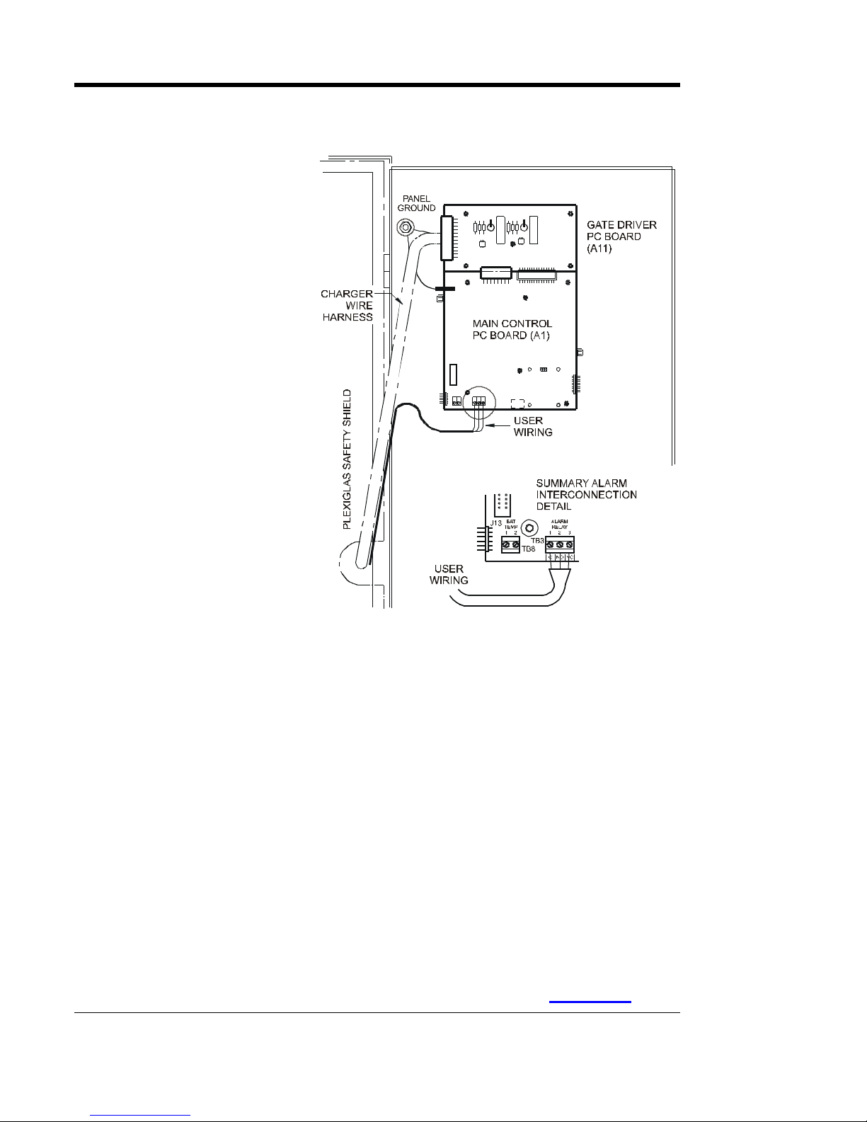
1.10 . WIRING TO THE REMOTE ALARM CONTACTS
Built-in Summary "Common" Alarm Relay (standard)
The AT10.1 Main
Control PC Boar d (A1)
is equipped with a
"common" Summary
Alar m r elay. This
relay contact transfers
when any one or more
of the standard AT10.1
alarms exist.
See Sections 2.2.7 and
2.3.4 for a list of these
alarms and status
codes. One form-C
alarm contacts are
provided, and
accessible via terminal
block (TB3), as shown
in the figure to th e
right.
Follow the procedure
below to wire an
annunciator to this
contact.
PROCEDURE
1. Allow 30in / 762mm of wire inside the enclosure. Excess will be trimmed.
2. Route annunciator wires to the AT10.1 front panel door by following the
3. Trim wires to the proper length for connecting to TB3. Strip 0.25in / 6.4mm
4. Make the connections at TB3, and securely tighten compression screws.
NOTES
1. Alarm contacts are rated at 0.5A / 125 Vac/Vdc.
2. Summary Alarm relay terminal block (TB3) is compression type, accepting
existing harness through the door hinge as shown. Use two (2) wire ties and
allow a 4-6in / 102-153mm loop for the hinge.
of insulation from the wires.
wire sizes #22-14 AWG.
3. Terminals are labeled in non-alarm condition.
4.
If user alarm contacts (TB3 and/or TB4A/B) are to drive inductive dc loads
(e.g. a larger dc relay) an external protective diode must be applied at the dc
relay to avoid equipment damage. See Application Note (JD5011-00
).
18

INSTALLING THE AT10.1
Auxiliary Alarm Relay PC Board (optional)
T he op tiona l A ux iliary A larm Re lay PC Board (A5) , m ounted on the right
side panel of the circuit breaker br a c ke t, pr ovides two (2) form-C conta c ts
(TB4-1 through TB4-36) for each of the following individual alarms:
• High DC Voltage
• Low DC Voltage
• DC Output Failure
• AC Input Failure
• Ground Fault Detection (positive or negative)
• Summary (common) Alarm
Alarm conta c ts (TB4A/B), marke d in non-alarm condition, ar e a s follows:
HVDC HVDC LVDC LVDC
C, NC, NO C, NC, NO C, NC, NO C, NC, NO C, NC, NO C, NC, NO C, NC, NO C, NC, NO C, NC, NO C, NC, NO C, NC, NO C, NC, NO
1 2 3 4 5 6 7 8 9 10 11 12 13 14 15 16 17 18 19 20 21 22 23 24 25 26 27 28 29 30 31 32 33 34 35 36
DC OUT
FAILURE
DC OUT
FAILURE AC FAIL AC FAIL
GROUND
DETECT
GROUND
DETECT SUMMARYSUMMARY
PROCEDURE
1. Deenergize and lock out all ac and dc voltages to the AT10.1.
2. Allow internal voltages to dissipate, then check with a voltmeter.
3. Remove the Plexiglas safety shield.
4. Route your remote annunciator wiring into the enclosure through one of the
unused conduit knockouts on the side of the enclosure.
5. As shown in the figure above, connect the wiring (use #22-14 AWG) to the
appropriate terminals of TB4 on the Auxiliary Alarm Relay PC Board (A5).
6. Strip each wire 0.25in / 6.4mm and securely tighten the terminal screws.
7. Replace the safety shield and restart the AT10.1.
NOTES
1. Alarm contacts are rated at 0.5A / 125 Vac or Vdc.
2. Terminal block (TB4) is compression type, accepting #22-14 AWG wire.
3. Terminals are labeled in non-alarm condition.
4. For a detailed view of the optional Auxiliary Alarm Relay PC Board (A5),
refer to drawing (JE5030-29
) listed in Appenix C on Page 80.
19

INSTALLING THE AT10.1
1.11. INSTALLING THE TEMPCO PROBE ASSEMBLY (OPTIONAL)
The temperature compensation (or TempCo) probe contains a
tempera ture - de pende nt r e sistor in an e poxy module that you install near
your batter y. The r e a re thr e e ( 3) steps in installing t he a ssem bly :
1. Mounting the probe assembly near the battery.
2. Installing an interconnection cable from the probe assembly to the AT10.1.
3. Wiring the charger end of the cable to a terminal block on the AT10.1.
The ac tual temperatur e c ompensa tion probe (A10), or puc k, is the same
for all battery types and all output voltages of the AT10.1. The accessory
part numbers differ de pe nding on ca ble length orde re d. See the tables in
Appendix B on page 71 for ordering information. Each kit contains
detailed Installation Instructions (JA5015-00
Applica tion N ote (JD5003-00
) for further user details. The main
elements of the installation are outlined below.
! WARNING
High voltages appear at several points inside the AT10.1. Use extreme
caution when work ing inside the e nc los ure . D o not atte mpt to work
inside the AT10.1 unless you are a qualified technician or electrician.
), a nd a se pa ra te
Disconnect and lock out all power from the AT10.1 bef ore starting to
remov e or re plac e any c omponents. Turn the ac powe r off at the
distribution panel upstream f rom the charger. Disc onnect the battery
from the AT10.1 output terminals TB1(+/-).
PROCEDURE
1. De-energize and lock out all ac and dc voltage sources to the AT10.1, and
check with a voltmeter before proceeding.
2. Mount the probe on a clean, dry surface, as close to the battery as possible,
such as the battery rack. DO NOT mount the probe:
• on the battery itself
• on unpainted wood, or bare galvanized metal.
• on plastic surfaces
3. To apply the probe, clean the mounting surface with isopropyl alcohol, and
allow to dry thoroughly. Remove the protective backing from the doublefaced adhesive tape on the probe, and securely press it onto the surface.
4. Install the cable supplied with the temperature compensation probe kit:
• Start at the AT10.1. The end of the cable with two (2) stripped wires and
a quick-connect terminal will be installed inside the AT10.1.
• Leave 30in / 762mm of cable inside the enclosure, and route the other
end to the probe at the battery.
20

INSTALLING THE AT10.1
• Run the cable though a conduit if possible, but not through a conduit
containing any power wiring.
NOTICE
If the s tandard (25ft / 7.6m) c able is not long enough, longer cable
assemblies ar e av ailable in lengths of 50, 100 & 200ft / 15.2, 30. 5 &
61.0m. See Appendix B on page 71 for ordering inf or m ation.
• Make sure all wiring conforms to NEC, local, and site requirements.
5. Attach the interconnection cable to the AT10.1 as shown in the figure below:
• Route the
cable within
the AT10.1
enclosure so it
runs with the
wire harness
to the back of
the front
panel, and
easily reaches
the Main
Control PC
Board (A1).
• Route the other end to the probe at the battery and coil up excess cable.
• At the Main
Control PC
Board (A1),
insert one of
the bare wires
from the cable
into each
terminal of
TB8. Polarity
is not vital.
• Plug the connector at the end of the nylon-shielded wire of the cable
assembly onto J6.
• Using plastic wire ties, fasten the interconnection cable loosely to the
existing wire harness. Make sure that the cable conforms to the service
loop at the hinge end of the door.
6. At the battery, connect the quick-connect terminals to the temperature
compensation probe. Polarity is not vital. Coil up any excess wire and tape
or tie it together to prevent damage.
7. Set jumper (J30) on the Main Control PC Board (A1) to positions 2-3 to use
compensated voltages, or to positions 1-2 to use uncompensated voltages.
21

INSTALLING THE AT10.1
8. Check your work. Confirm that:
• All connections are secure.
• The shield is connected to ground at the charger end only (A1-J6).
• The cable is connected to the 2-position terminal block (TB8) on the
Main Control PC Board (A1). Other terminal blocks may look similar.
9. Restart the AT10.1 using the startup procedure in Section 2.1. During
startup, the AT10.1 displays Pb on the front panel meter, indicating that the
temperature compensation is set up for lead-acid battery types. While this is
being displayed, you can press any front panel key to change the display to
read nicd, to change the temperature compensation setup for nickel-
cadmium batteries. The choice you make is saved internally, and will be
used again by the AT10.1 the next time it starts.
10. Adjust the output float and equalize voltages to the battery manufacturer's
recommended values, using the AT10.1 front panel meter, as described in
Section 2.3.2.
If the temperature compensation probe, or the probe wi ri ng, i s
damaged and becomes an open circuit, t he AT10.1 detect s the
damage and displays E 08 on the front panel meter. The
AT10. 1 t hen reverts t o normal non-temperature-compensated
operation unt il the probe or wiring is repaired. Once the probe
is repaired, you must restart the AT10.1 to act i vate the probe,
as described in Section 2. 1.
NOTICE
Using temperature compensation
When an electric storage battery is being charged, the terminal voltage of
the battery c ha nges a small amount whenever the ba tter y te mper a tur e
changes. As the battery temperature increases, its terminal voltage
decreases. When a constant output voltage float type rectifier charges a
battery, float current increases when the temperature increases. This
results in overcharging the battery, which can result in damage to the
materials, or at least the need for more frequent maintenance.
When the AT10.1 is equipped with a temperature c ompe nsa tion probe, it
is able to adjust the output voltage applied to the battery to keep the float
curre nt c onstant, ther e by a voiding overchar ging. The pr obe se nse s the
ambient temperature at the battery, and adjusts the output float/equalize
voltages to compensate for variations in temperature. If the ambient
temperature increases, the AT10.1 output voltage decreases.
If you are experiencing any inconsistencies in the AT10.1 when the
tempera ture c ompensa tion probe is utilized, tempora r ily disc onne c t the
probe, a nd r e fer to the Ap plication Note (JD5003-00
) for further details.
22

INSTALLING THE AT10.1
N ote t he follow ing:
• You should set the Float and Equalize voltages to the values
recommended by your battery manufacturer for 77 °F / 25 °C.
• When you enter the Edit Mode to adjust the Float or Equalize voltage
(see Section 2.3.2), the front panel meter displays the 77 °F / 25 °C value
for the Float or Equalize voltage, even if the battery is warmer or cooler
than 77 °F / 25 °C.
• The actual output voltage of the AT10.1 may be different from the value
displayed on the front panel meter, if the battery is warmer or cooler than
77 °F / 25 °C.
• Use a digital meter to measure the actual output voltage of the AT10.1.
If you know the temperature at the temperature compensation probe, you
can use the graph below to determine that the output voltage is correct.
• If the battery temperature goes below 32 °F / 0 °C, there will be no
further increase in AT10.1 output voltage. Likewise, if the battery
temperature goes above 122 °F / 50 °C, there is no further decrease in
output voltage.
OUTPUT VOLTAGE VS BATTERY TEMPERATURE
108
106
104
102
Nicke l- Cadmium
100
Percent Ou t put Voltage
98
96
94
20 40 60 80 100 120
Temp erature, Degrees Fah renh eit
Lead-Acid
Example:
100 Deg. F
97% Output
Voltage
EXAMPLE: Suppose you have a lead-acid battery whose temperature is
100 °F / 37.8 °C. As shown on the graph, the output voltage should be
approximately 97% of the 77 °F voltage. If the float voltage is set on the
front panel to 132 Vdc, the actual output voltage will be:
132 x 0.97 = 128 Vdc
1.12 . INSTALLING FOR REMOTE COMMUNICATION (OPTIONAL)
Refer to separate Ope rating Instructions (JA0102-04
1.13 . INSTALLING FOR FORCED LO AD SHARING (OPTIONAL)
Refer to Appendix F on page 92 or Op e rating Instructions (JA5054-00).
).
23

OPERATING THE AT10.1
2. OPERATING THE AT10.1 BATTERY CHARGER
2.1. STARTING THE AT10.1
2.1. 1. Underst anding th e st art up sequence
The AT10.1 is set up at the factory to work with most common batteries
and loads without further a djustment. When you start the AT10.1 for the
first time, the factory settings (float voltage, equalize voltage, etc.) control
the opera tion of the charger. Y ou c a n c ha nge the se ttings after you sta r t
the AT10.1. The FACTORY SETTINGS are listed in table on pa ge 25.
The AT10.1 startup routine takes a bout 5 sec onds. The microproc e ssor
that controls the AT10.1 initializes the charger by reading the settings that
are stored internally. The control circuitry then "soft starts" the AT10.1,
and the dc output voltage and current increase gradually to the rated value.
2.1. 2. Checking th e instal lation
Confirm that you have followed the installa tion
instruc tions care fully. Chec k the a c input
supply voltage a nd the ba tter y voltage, and
make sur e they ma tc h the infor ma tion on the
AT10.1 data nameplate. Verify that the
jumpers on the m ai n transformer ( T1) are
correc t for your ac supply vol tage . Open the
front panel door and care fully chec k the battery
polarity at the dc output terminals TB1(+/-).
2.1. 3. Starti ng th e AT10.1
When you are sur e tha t all connections to the
AT10.1 are pr ope r ly made, follow these ste ps
to start up the AT10.1:
• Turn on (close) the dc output circuit breaker (CB2) first.
• The digital meter indicates battery voltage only. If the meter display
does not light, do not proceed. Turn off (open) the dc breaker (CB2).
• Check all connections and the battery polarity again. Also check the
battery voltage. It must be above 50% of nominal voltage to turn on the
display. If you cannot find the problem, refer to the Troubleshooting
Procedure in Section 3.1 on page 44.
If you at t empt to turn on the dc circuit breaker (CB2) w ith the batt ery
connected in reverse polarity, t he breaker w ill immediately trip. Do not
try to close the dc breaker again, since t hi s may damage the AT10.1. If
your AT10.1 is equipped wi t h dc f uses, one or bot h fuses will blow when
the battery is reversed. Correct t he battery polarity before proceeding.
Using the Digital Meter
When you first start the
AT10.1, the meter display
alternates between dc output
voltage and dc output current.
Each reading is held for 2
seconds. Indicator lights to
the l eft of the display indicate
whether the meter is
displaying voltage or current.
If you want to “freeze” the
meter to display only vol tage,
press the METER MODE
key on the front panel. To
freeze the meter to display
only current, press the key
again. Press the key twice
more to revert to the
alternating display.
NOTICE
24
 Loading...