

Page 1
We’ve been there when you need.
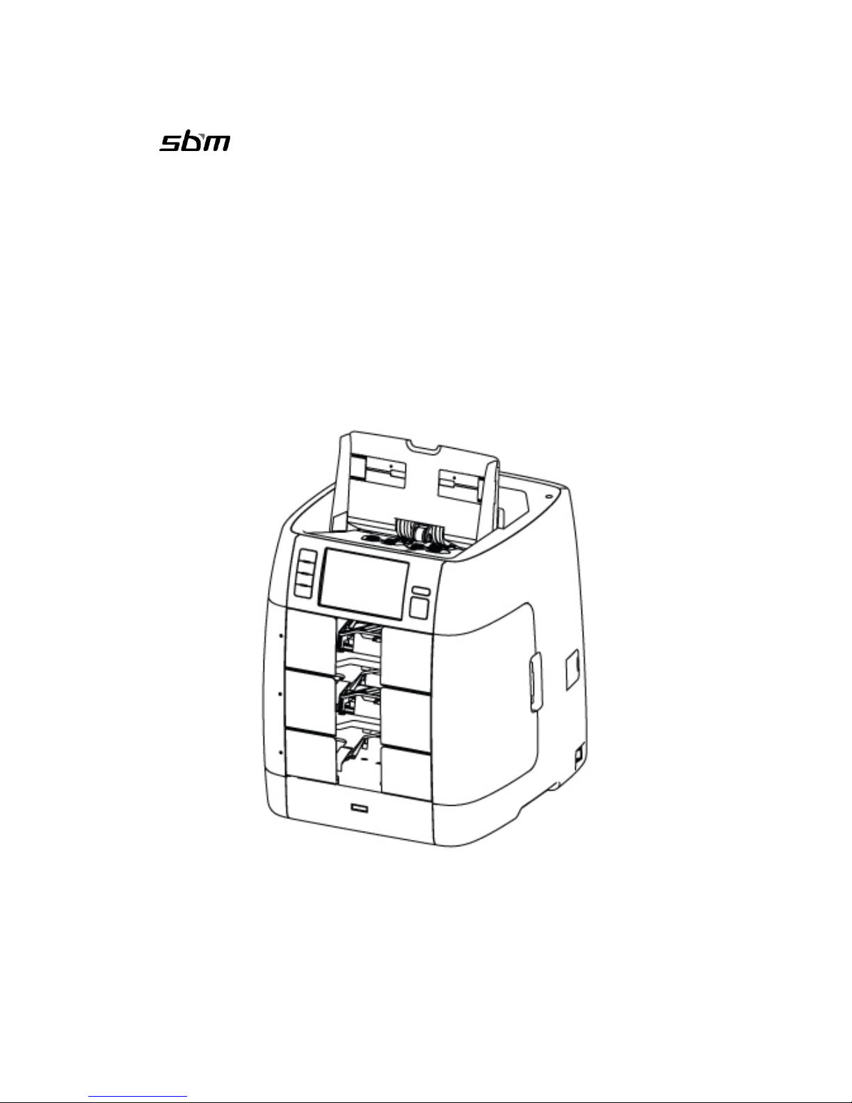
SB-3000
Currency Discrimination Fitness Sorter
SEVICE MANUAL
Ver. 1.5
SBM Co., LTD
Head Office/ R&D Center
6F, Hyunwoo Bldg 206, Anayang 7-Dong, Manan-Gu, Anyang-City, Gyeonggi-Do, Korea 430-817
Page 2

2
Note
The information or material contained in this document is the property of SBM. Any recipient of
the information or material contained in this document shall not disclose or divulge, directly or
indirectly, this document or the information or material contained herein without the prior written
consent of SBM.
All copyrights, trademarks, patents and other rights in connection herewith are expressly
reserved to SBM and no license is created hereby.
The above duty of confidence also entails a prohibition of reproduction of this text without
specific authority, in writing, from SBM.
Page 3

3
Every person working at the Fitness Sorter; SB-3000 must have previously read and understand
the user manual and, specially the safety information. The Fitness Sorter; SB-3000 may only be
operated by authorized personnel and may be serviced by trained and authorized personnel.
Safety Information
Always be careful when using the machine. To reduce the risk of fire, electrical shocks,
and other injuries, keep these safety considerations in mind when installing, using, and
maintaining your machine:
Stability
Place the machine on a secure, stable surface. The machine can be seriously damaged
if it falls.
Power Supply
Provide correct power to the machine, as listed on the back of the machine. If you are
not sure of the type of power that is supplied to your office, call your electric company.
Grounding
If the plug has three prongs, it must be plugged into a grounded (three hole) outlet.
Grounded plugs and outlets are designed for your safety - do not try to make a three-
prong plug fit into a two-prong outlet by modifying the plug or outlet in any way. If you
cannot insert the plug into your wall outlet easily, then a qualified electrician should
inspect the outlet.
Overload
Do not plug too many electrical devices into a wall outlet or an extension cord. An
overloaded outlet could be a reason of a fire and electrical shock hazard.
Cleaning
Before cleaning the machine, unplug it from the power outlet. Clean exposed parts with
a soft cloth slightly dampened with water. Do not use aerosol cleaners.
Gas Leaks
Never use any machine close to a gas leak. If you think gas is leaking, call the gas
company immediately. A small electrical spark in the machine could cause a fire or
explosion.
Page 4

4
Precaution
When using the machine, these precautions should always be followed:
1. Never push objects of any kind into your machine through the case or cabinet
openings.
2. Do not use your machine near water, in wet locations, or outdoors.
3. Do not allow anything to rest on the power cord, line cord, or PC interface cable.
Do not locate your machine where the cords can be damaged by persons’ walking
on them.
4. Do not allow pets to chew on the power cord or PC interface cable.
5. Use supplies or cleaning materials only as directed. Keep all supplies and
materials out of the way of children.
6. The power supply turns this machine on and off. Make sure that your machine is
installed near an outlet and is easily accessible.
7. Never remove covers or guards that require a tool for removal. There are no
operator serviceable areas inside your machine. Refer servicing to authorized
service personnel.
8. Never defeats interlock switches. This machine is designed to restrict operator
access to unsafe areas. Covers, guards and interlock switches are provided to
ensure that the machine will not operate with covers opened.
9. Risk of explosion if battery is replaced by an incorrect type. Dispose of used
batteries according to the instruction.
Managing the performance of the machine
This unit has many sophisticated sensors. Without proper maintenance, it cannot last its
good performance. Please read the ‘Chap8 Maintenance’ section of this manual
carefully, and do it everyday. When the performance is deteriorated on a sudden, please
clean all the sensors first before calling a service.
Page 5
5
Safety Notes
Your machine and the supplies are designed and tested to meet strict safety
requirements. Included are safety agency examination and approval and compliance to
established environmental standards. Please read the following instructions carefully
before operating your machine, and refer to them as needed to ensure the continued
safe operation of your machine.
Battery is used for ‘PBA POCKET’ in this machine. If wrong date and time are displayed
on LCD after correct setting, it is necessary to change the battery of ‘PBA POCKET’.
Please read the following instructions carefully before changing the battery.
Either the symbol , or a similar symbol, combined with the triangle shaped
warning sign from ISO 3864-2, or the following statement or equivalent text shall be
used:
WARNING
Hazardous moving ports!
Keep fingers and other body parts away
WARNING
Hazardous moving parts keep away from moving fan blades.
Page 6
6
FCC Compliance Statement
This manual user general symbols for safety information and symbols to identify special
dangers.
Refer to the below Icons before reading Manual.
Icon Word Explanation
DANGER
WARNING
This symbol with the signal word (Danger/ Warning) refers
to an immediate risk to life or health
CAUTION
This symbol is to identify safety information. Ignoring this
warning can result in damage to the system or endanger
data consistency.
THIS DEVICE COMPLIES WITH PART 15 OF FCC RULES.
OPERATION IS SUBJECT TO THE FOLLOWING CONDITIONS:
THIS DEVICE MAY NOT CAUSE HARMFUL INTERFERENCE, AND THIS
DEVICE MUST ACCEPT ANY INTERFERENCE RECEIVED, INCLUDING
INTERFERENCE THAT MAY CAUSE UNDESIRED OPERATION.
Page 7
7
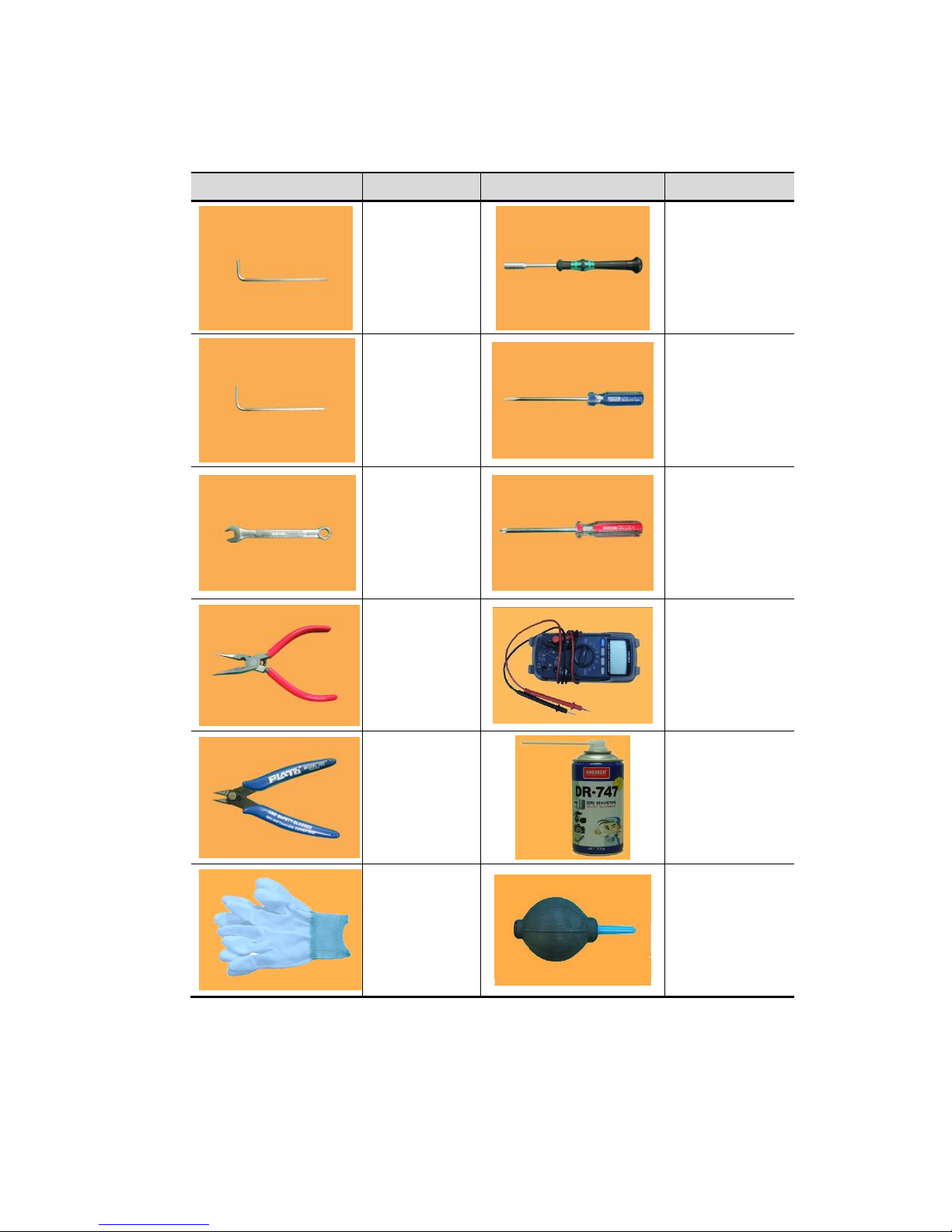
Recommended Tools
Picture Name and Spec.
Picture Name and Spec.
L Wrench
Ø1.5
Hexagonal
Screwdriver
5mm
L Wrench
Ø2
Screwdriver(-)
2.5mm
Spanner
7mm
Screwdriver(+)
Ø6
Long-Nose
Multi-Meter
Nipper
Dust Blower
Aerosol
Anti-Static
Gloves
Rubber Coated
Dust Air Blower
Dust Blower: Dust may cause to make a short in PCB so periodically clear dust apt to be
accumulated inside of machine.
Anti-Static Gloves: In maintenance or repairing, recommended to put it on to protect static
caused to make a short.
Page 8

8
CONTENTS
1.0.0. INSTALLATION ------------------------------------------------------------------------------------------------------ 13
2.0.0. DESCRIPTION OF THE PARTS ------------------------------------------------------------------------------- 15
2.1.0. EXTERIOR VIEW ----------------------------------------------------------------------------------------------- 15
2.1.1. FRONT VIEW ------------------------------------------------------------------------------------------------- 15
2.1.2. REAR VIEW --------------------------------------------------------------------------------------------------- 15
2.1.3. INTERFACE VIEW ------------------------------------------------------------------------------------------- 16
2.2.0. INTERIOR VIEW ------------------------------------------------------------------------------------------------ 16
2.2.1. INSIDE VIEW (LEFT) ---------------------------------------------------------------------------------------- 16
2.2.2. INSIDE VIEW (RIGHT) -------------------------------------------------------------------------------------- 17
2.2.3. INSIDE VIEW (REAR) --------------------------------------------------------------------------------------- 17
2.3.0. PARTS -------------------------------------------------------------------------------------------------------------- 18
2.3.1. SENSOR -------------------------------------------------------------------------------------------------------- 18
2.3.2. ROLLERS ------------------------------------------------------------------------------------------------------ 23
2.3.3. PULLEY ---------------------------------------------------------------------------------------------------------- 24
2.3.4. TIMING BELTS ------------------------------------------------------------------------------------------------ 25
2.4.0. FUNCTION OF EACH BOARD -------------------------------------------------------------------------------- 26
3.0.0. OVERALL OF CONTROL --------------------------------------------------------------------------------------- 32
3.1.0. OVERALL OF CONTROL PANEL --------------------------------------------------------------------------- 32
3.2.0. OVERALL OF TOUCH SCREEN ---------------------------------------------------------------------------- 33
4.0.0. PREPARATION OF OPERATION ----------------------------------------------------------------------------- 35
4.1.0. READY FOR BANKNOTES ---------------------------------------------------------------------------------- 35
4.2.0. HOW TO ADJUST THE BILL GUIDE HOPPER -------------------------------------------------------- 36
4.3.0. HOW TO PLACE NOTES INTO THE HOPPER -------------------------------------------------------- 36
4.4.0. COUNTING ------------------------------------------------------------------------------------------------------ 37
5.0.0. BASIC OPERATION ----------------------------------------------------------------------------------------------- 38
5.1.0. PROCEDURE OF OPERATION ----------------------------------------------------------------------------- 38
5.1.1. FLOW CHART ------------------------------------------------------------------------------------------------- 38
5.1.2. CURRENCY SETTING ------------------------------------------------------------------------------------- 39
5.1.3. WORKING MODE SETTING ------------------------------------------------------------------------------ 39
5.1.4. COUNTING RESULT CONFIRMATION ----------------------------------------------------------------- 41
5.1.5. GRAND TOTAL ----------------------------------------------------------------------------------------------- 43
Page 9

9
5.1.6. PRINTING ------------------------------------------------------------------------------------------------------- 45
5.1.7. REJECT REASON (for SVC) ------------------------------------------------------------------------------ 48
5.2.0. WORKING MODE & FUNCTION ---------------------------------------------------------------------------- 49
5.2.1. SUMMARY ------------------------------------------------------------------------------------------------------ 49
5.2.2. BASIC WORKING MODE ---------------------------------------------------------------------------------- 49
■ FITNESS Mode --------------------------------------------------------------------------------------------- 49
■ COUNT Mode ------------------------------------------------------------------------------------------------ 51
■ FACE Mode -------------------------------------------------------------------------------------------------- 52
■ ORIENT Mode ----------------------------------------------------------------------------------------------- 52
■ ISSUE Mode ------------------------------------------------------------------------------------------------- 53
■ DISPENSE Mode ------------------------------------------------------------------------------------------- 54
■ OCR Mode ---------------------------------------------------------------------------------------------------- 55
5.2.3. USER DEFINED MODE ------------------------------------------------------------------------------------ 57
5.2.4. FUNCTIONS --------------------------------------------------------------------------------------------------- 59
6.0.0. USER MENU (for USER) ---------------------------------------------------------------------------------------- 62
■ LANGUAGE -------------------------------------------------------------------------------------------------- 63
■ MY GRAND TOTAL ---------------------------------------------------------------------------------------- 63
■ COUNT INFERFACE -------------------------------------------------------------------------------------- 63
1. START COUNTING ------------------------------------------------------------------------------------- 63
2. POCKET CAPACITY ----------------------------------------------------------------------------------- 64
3. ACCEPT RESULT --------------------------------------------------------------------------------------- 64
4. PRINT RESULT ------------------------------------------------------------------------------------------- 64
■ USER INTERFACE ----------------------------------------------------------------------------------------- 64
1. TOUCH CALIBRATION -------------------------------------------------------------------------------- 64
2. SET DATE/ TIME ---------------------------------------------------------------------------------------- 64
3. SELECTION WAY --------------------------------------------------------------------------------------- 64
4. SORTING ORDER -------------------------------------------------------------------------------------- 64
5. LCD BRIGHTNESS ------------------------------------------------------------------------------------- 64
6. BEEP ------------------------------------------------------------------------------------------------------- 64
7. POWER SAVING ---------------------------------------------------------------------------------------- 64
■ INFORMATION ---------------------------------------------------------------------------------------------- 65
1. ABOUT SB3000 ----------------------------------------------------------------------------------------- 65
2. A/S CALL NUMBER ------------------------------------------------------------------------------------ 65
■ FACTORY DEFAULT --------------------------------------------------------------------------------------- 65
Page 10

10
7.0.0 ADMIN MENU (for ADMINISTRATOR) ------------------------------------------------------------------------- 66
■ LOADING DEFAULT --------------------------------------------------------------------------------------- 67
■ CHAGNE PASSWORDS ---------------------------------------------------------------------------------- 67
■ MACHINE SETTING --------------------------------------------------------------------------------------- 67
1. STATION ID ----------------------------------------------------------------------------------------------- 67
2. ETHERNET ------------------------------------------------------------------------------------------------ 67
3. PRINTER -------------------------------------------------------------------------------------------------- 67
4. CUSTOMER DISPLAY --------------------------------------------------------------------------------- 68
■ VALUE SETTING ------------------------------------------------------------------------------------------- 68
1. CF LEVEL ------------------------------------------------------------------------------------------------- 68
2. FITNESS -------------------------------------------------------------------------------------------------- 69
■ FUNCTION ON/OFF --------------------------------------------------------------------------------------- 72
1. CF ITEMS ------------------------------------------------------------------------------------------------- 72
2. TAPE IN OUNT MODE -------------------------------------------------------------------------------- 72
■ USER SETTING --------------------------------------------------------------------------------------------- 72
1. CONCURRENT USER --------------------------------------------------------------------------------- 72
2. SETTING PLACE --------------------------------------------------------------------------------------- 73
■ GRAND TOTAL ---------------------------------------------------------------------------------------------- 73
1. GRAND TOTAL TYPE --------------------------------------------------------------------------------- 73
2. CLEAR ----------------------------------------------------------------------------------------------------- 73
3. INITIALIZE ALL ------------------------------------------------------------------------------------------ 73
4. SUMMARY ------------------------------------------------------------------------------------------------ 73
5. EACH USER --------------------------------------------------------------------------------------------- 74
■ LOG DATA ---------------------------------------------------------------------------------------------------- 76
8.0.0. SEVICE MENU ------------------------------------------------------------------------------------------------------ 78
8.1.0. SAVING DEFAULT ------------------------------------------------------------------------------------------------ 79
8.2.0. ADMIN PWD ------------------------------------------------------------------------------------------------------ 79
8.3.0. DOWNLOAD TARGET ----------------------------------------------------------------------------------------- 79
8.4.0. MACHINE MANAGEMENT ----------------------------------------------------------------------------------- 80
8.4.1. PROGRAM UPDATA ---------------------------------------------------------------------------------------- 80
8.4.2. TOUCH CALIBRATION ------------------------------------------------------------------------------------- 80
8.4.3. CALIBRATION (SHADING) -------------------------------------------------------------------------------- 80
8.4.4. MACHINE TEST ---------------------------------------------------------------------------------------------- 81
8.4.5. LOG DATA ------------------------------------------------------------------------------------------------------ 83
8.5.0. MACHINE SETTING -------------------------------------------------------------------------------------------- 84
Page 11

11
8.5.1. SET DATE/ TIME ----------------------------------------------------------------------------------------------- 84
8.5.2. SET A/S CALL -------------------------------------------------------------------------------------------------- 84
8.5.3. ETHERNET ---------------------------------------------------------------------------------------------------- 84
8.6.0. VALUE SETTING ------------------------------------------------------------------------------------------------ 84
8.6.1. CF LEVEL ------------------------------------------------------------------------------------------------------ 84
8.6.2. HOPPER LEVEL ---------------------------------------------------------------------------------------------- 85
8.6.3. DOUBLE LEVEL ---------------------------------------------------------------------------------------------- 85
8.6.4. FITNESS -------------------------------------------------------------------------------------------------------- 85
8.7.0. FUNCTION ON/OFF -------------------------------------------------------------------------------------------- 92
8.7.1. CF ITEMS ------------------------------------------------------------------------------------------------------ 92
8.7.2. TAPE IN COUNT MODE ------------------------------------------------------------------------------------ 93
8.8.0. ABOUT SB3000 -------------------------------------------------------------------------------------------------- 93
9.0.0. CALIBRATION (SHADING) ------------------------------------------------------------------------------------- 94
9.1.0. CIS CALIBRATION ---------------------------------------------------------------------------------------------- 94
9.2.0. TAPE CALIBRATION ------------------------------------------------------------------------------------------- 98
9.3.0. UV CALIBRATION ---------------------------------------------------------------------------------------------- 100
9.4.0. MR CALIBRATION ---------------------------------------------------------------------------------------------- 102
10.0.0. ADJUSTMENT ---------------------------------------------------------------------------------------------------- 104
10.1.0. GAP BETWEEN SEPARTOR AND ADF ROLLER ---------------------------------------------------- 104
10.2.0. PICK-UP POSITION SENSOR ----------------------------------------------------------------------------- 106
10.3.0. GAP OF SELECTOR ----------------------------------------------------------------------------------------- 107
10.4.0. TIMING BETWEEN PICK-UP AND ADF ROLLER ---------------------------------------------------- 109
10.5.0. THE HOPPER LEVEL ---------------------------------------------------------------------------------------- 110
11.0.0 S/W UPGRADE ---------------------------------------------------------------------------------------------------- 111
11.1.0. S/W VERSION AND CURRENY CHEDK ---------------------------------------------------------------- 111
11.2.0. UPGRAD BY USER MEMORY STICK ------------------------------------------------------------------- 112
11.3.0. UPGRAD BY VOL PROGRAM IN PC -------------------------------------------------------------------- 113
12.0.0. GETTING DATA --------------------------------------------------------------------------------------------------- 115
13.0.0. TROUBLESHOOTING -------------------------------------------------------------------------------------------- 122
■ ERROR ON INITIAL OEPRIATING -------------------------------------------------------------------------------- 122
■ ERROR ON OPERATING -------------------------------------------------------------------------------------------- 123
Page 12

12
14.0.0. MAINTENANCE ---------------------------------------------------------------------------------------------------- 124
14.1.0. SENSORTS ------------------------------------------------------------------------------------------------------ 124
14.2.0. ROLLERS --------------------------------------------------------------------------------------------------------- 131
14.3.0. DUST TRAP ------------------------------------------------------------------------------------------------------ 131
15.0.0. BOARD & COMPONENT ---------------------------------------------------------------------------------------- 132
15.1.0. Connection Diagram ------------------------------------------------------------------------------------------- 132
15.2.0. Board Descriptions --------------------------------------------------------------------------------------------- 133
16.0.0. DRAWINGS --------------------------------------------------------------------------------------------------------- 147
17.0.0. SPECIFICATION --------------------------------------------------------------------------------------------------- 253
Page 13
13
1.0.0. INTSTALLATION
Packing List
No. Part Name Qty Remark
1 SB-3000 1 Unit
2 AC Power Cord 1 pc.
3 User Manual 1 pc.
4 Cleaning Brush 1 pc.
5 Sensor Cleaning Cloth 1 pc.
6
Serial Cable
(Connection between SB-3000 & PC)
1 pc. Optional
7
Printing Cable
(Used in connecting a printer)
1 pc. Optional
※The manufacturer does not provide a Micro SD Memory Card.
Work Area
To help guarantee trouble-free operation of your machine, place it on a flat, stable
surface near your workstation.
Do not place our machine:
In direct sunlight
Near heat sources or air conditioners
In dusty or dirty environments
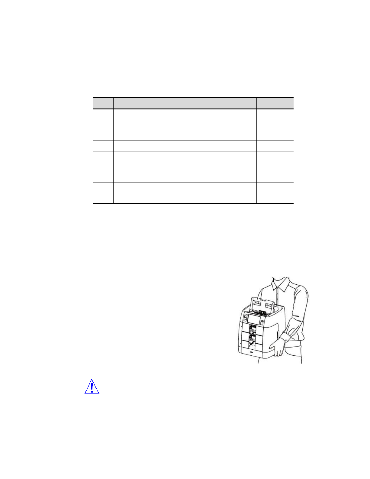
Handing
When handling or moving the machine, do not lift with
grasping the Front Area. The picture shows how to lift
the machine correctly. Please refer to the pictures as
right.
[How to move]
1 Get close to the machine and bend your knees.
2 Keep your back straight.
3 Check the center of weight and hold the grip tight.
4 When you turn the direction, do not twist your body but use your steps to turn.
(FIG 2-01)
Page 14
14
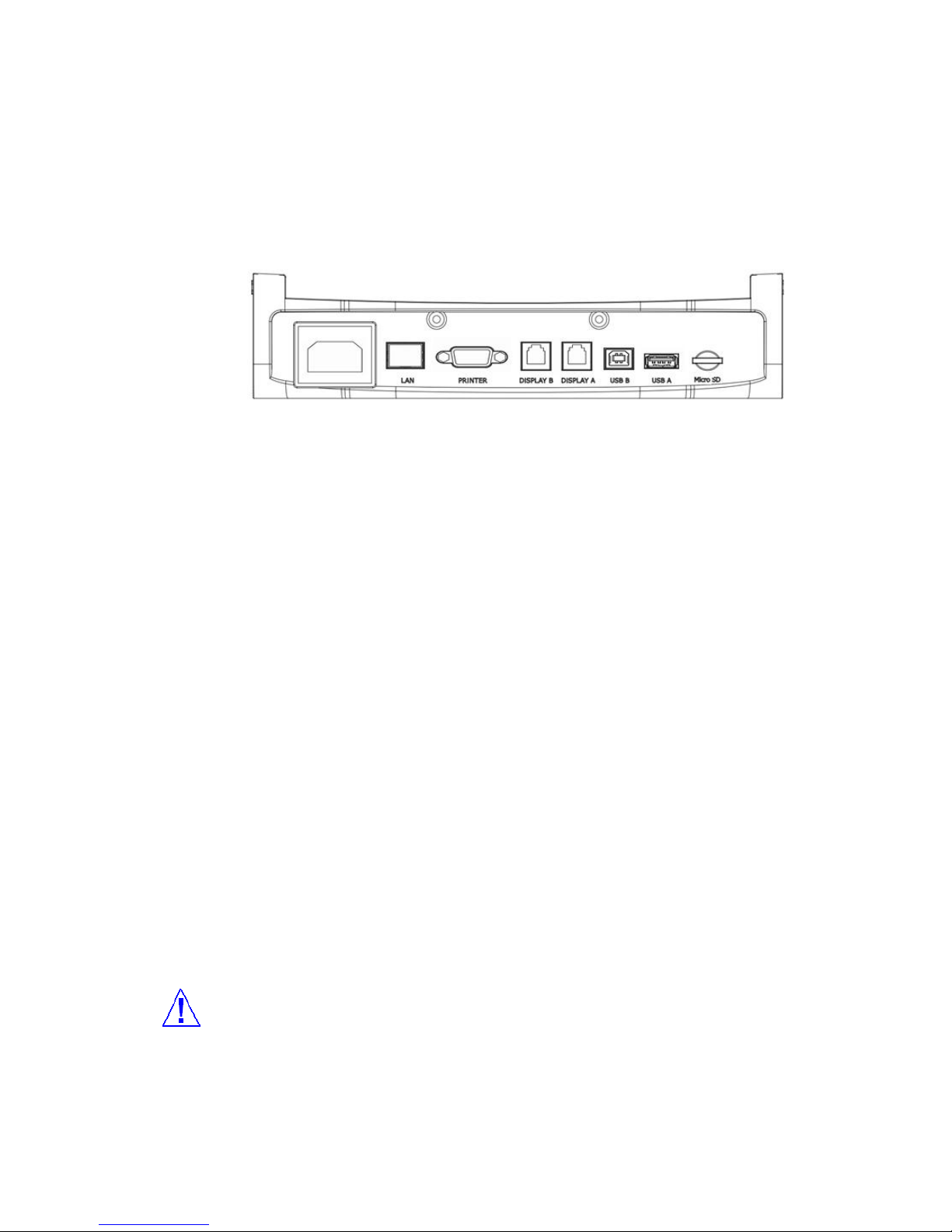
Connection
Plug one end of the cord into the back of the machine and the other end into a standard AC
power outlet.
Interface
[LAN]
1. The counting results is sent to PC though LAN
2. PC can control the set though LAN
3. The set can be upgrade through LAN
[Serial Pinter]
SB-3000 has a serial interface port, which allows you to connect your printer to print out counting
result. To connect your printer to the machine, follow the steps as below:
1. Make sure that both the SB-3000 and the printer are turned off.
2. Plug the cable of printer into the serial port of SB-3000.
3. Turn on the SB-3000 and set parameters referring to the Chapter 6 of this manual.
[Display A] & [Display B]
External Display [option] can be connected with these 2 ports
1 or 2 user can make the counting result display using these ports.
[USB A]
The set can be upgraded the firmware with USB Memory Stick.
[USB B]
The set can connect SB-3000 to PC with USB B. this port is for Service
1. The massive data will be sent to PC with high speed.
2. If there are problems in USB A, USB B will be the alternative port
[Micro SD]
Optional
[Warning]
If user inserts USB B into [Display A] or [Display B] port, electrical short can be happened. Please,
check the right port before inserting.
(FIG 2-02)
Page 15
15
2.0.0. DESCRIPTION OF THE PARTS
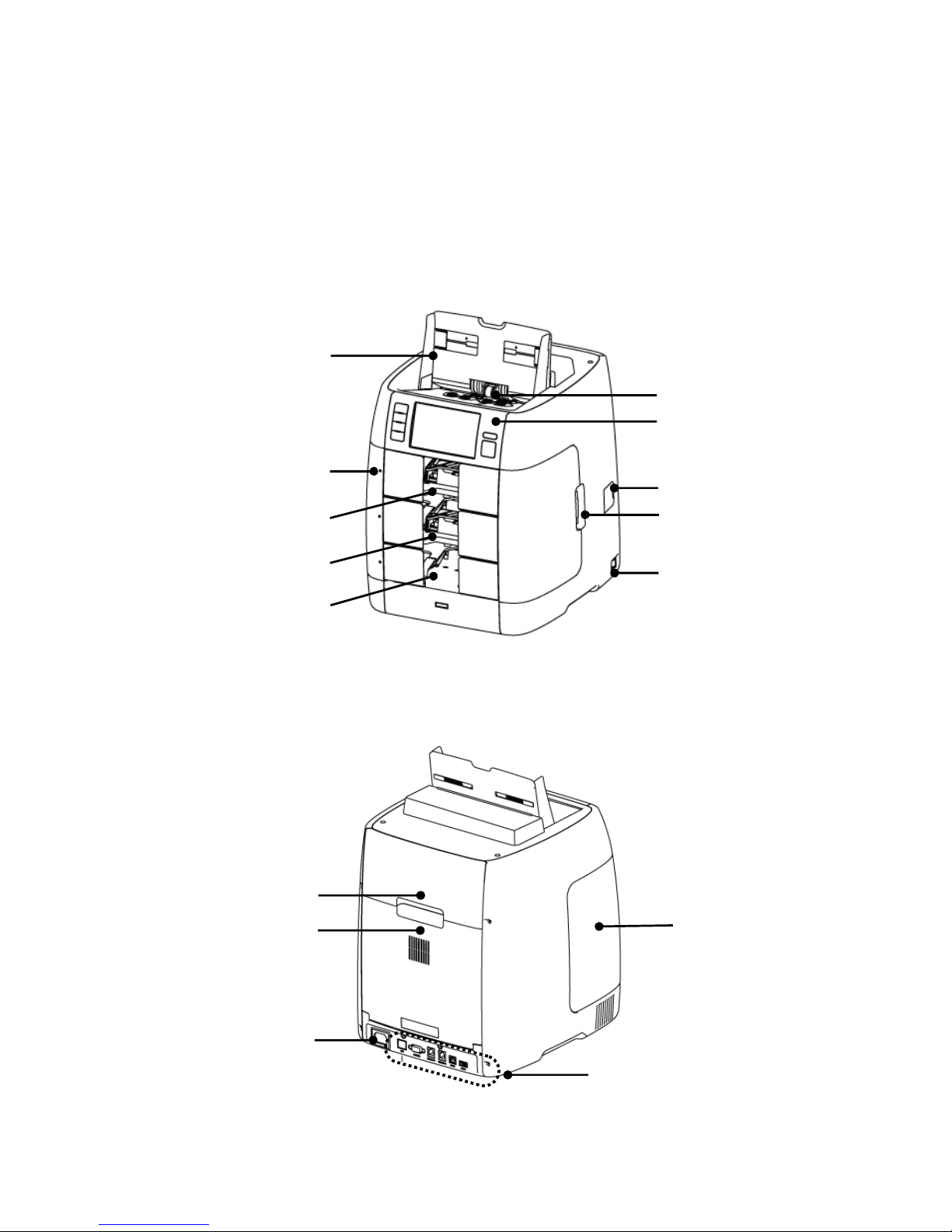
2.1.0. EXTERIOR VIEW
2.1.1. FRONT VIEW
2.1.2. REAR VIEW
BILL GUIDE
CONTROL PANEL
POCKET LED
STACKER #1
STACKER #2
REJECT POCKET
FRONT DOOR
POWER SWITCH
DUST CAP
REAR DOOR A
REAR DOOR B
AC POWER
INTERFACE
HOPPER
OPEN HANDLE
(FIG 3-01)
(FIG 3-02)
FRONT DOOR
Page 16
16
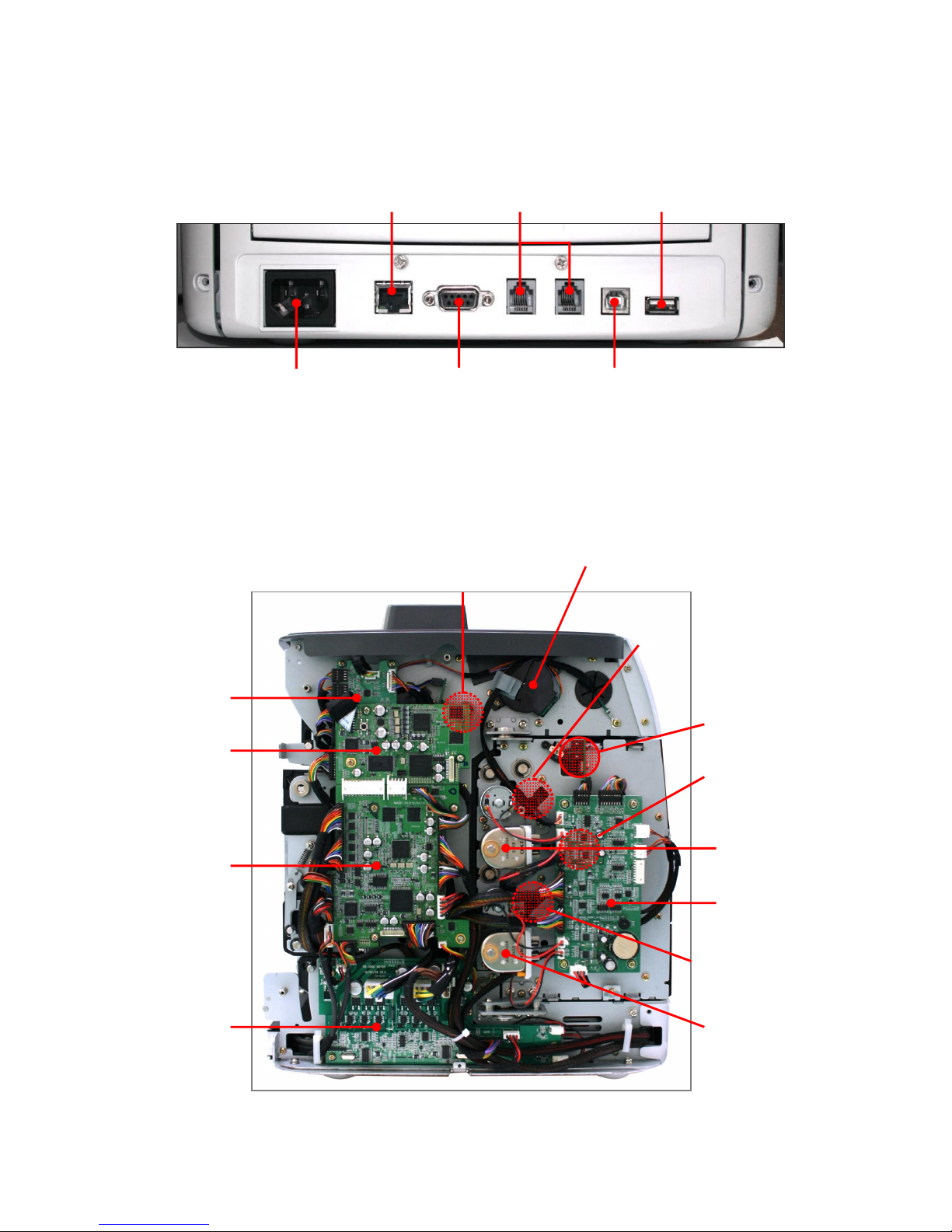
2.1.3. INTERFACE VIEW
2.2.0. INTERIOR VIEW
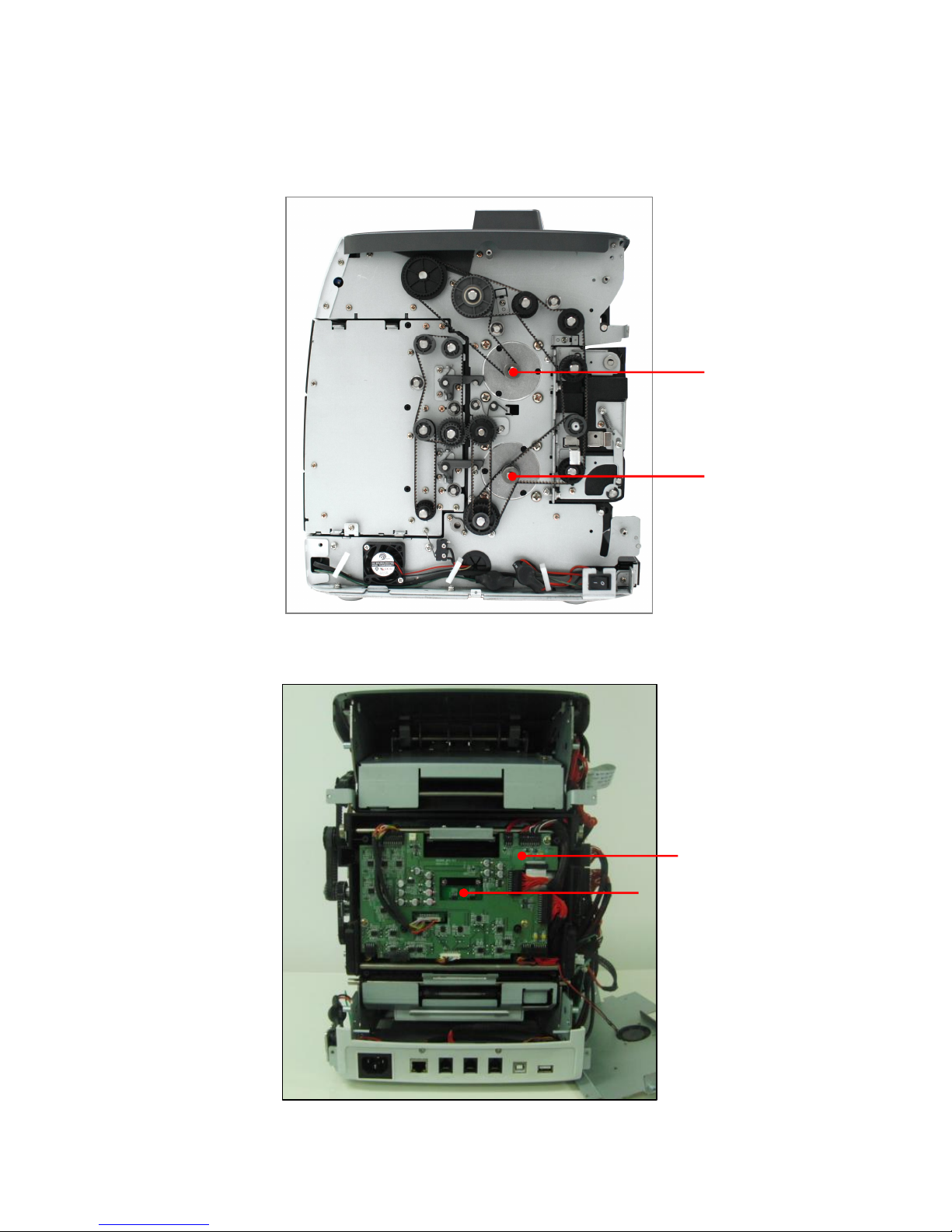
2.1.1. INSIDE VIEW (LEFT)
Feeding Motor Encoder
Pick up Position Sensor
(Inside)
Connector Board
Image 2 Board
Image 1 Board
Motor Board
Pocket Board
Solenoid 1
Solenoid 2
Overflow Sensor 2
Overflow Sensor 1
POWER CORD
LAN
PRINTER
(RS 232PORT)
(CUSTOEMR DISPLAY)
RJ11
USB B TYPE
(FOR PC CONTROL)
(FOR USB MEMORY STICK)
USB A TYPE
Hi/Low Sensor 1
Hi/Low Sensor 2
Page 17
17
2.1.2. INSIDE VIEW (RIGHT)
2.1.3. INSIDE VIEW (REAR)
Tape Detect Receive
MTU Board
Feeding Motor
Main Motor
Page 18
18
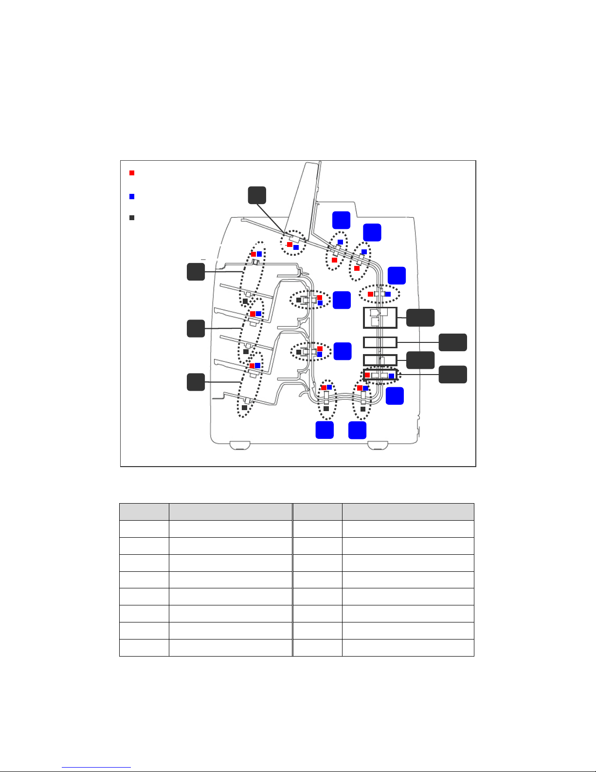
2.3.0. PARTS
2.3.1. SENSORS
■ Positions of Sensors
No Description No Description
① RP1 sensors, JAM1 position ⑨-1 CIS & Optional CIS
② RP2 sensors, JAM2 position ⑨-2 Tape Detection Module
③ RP3 sensors, JAM3 position ⑨-3 MR sensors
④ RP4 sensors, JAM4 position ⑨-4 UV sensors
⑤ RP5 sensors, JAM5 position ⑩ Hopper sensor
⑥ RP6 sensors, JAM6 position ⑪ Stacker1 sensor
⑦ RP7 sensors, JAM7 position ⑫ Stacker2 sensor
⑧ RP8 sensors, JAM8 position ⑬ Reject pocket sensor
①
②
③
④
⑤
⑥
⑦
⑧
⑩
⑫
⑬
⑨-1
⑨-2
⑨-3
⑨-4
⑪
T: TRN (Transmitter)
R: RCV (Receiver)
P: Prism
Page 19
19
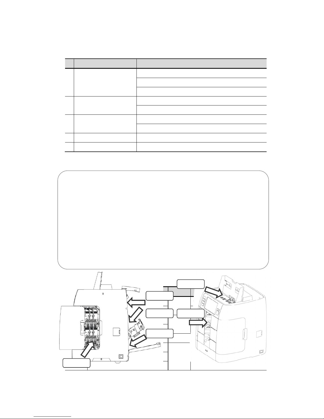
■ Specifications of Sensors
1
Sensor Specification
1 UV Sensors
1) 405nm Transmission 1ch (UV) X 2ea
2) 375nm Transmission 1ch (SUV) X 2ea
3) 375nm Reflection 2 ch (SUV) X 2ea
2 MR Sensors
1) 60mm MR ARRAY 6 ch X 1(EA)
2) 6mm MG SIGNLE X 6 (EA)
3 IR & White Sensor
1) 885 ~ 890nm, 100dpi Transmission Image
2) 50dpi WHITE Transmission Image
4 CIS sensor 455 ~ 645nm, 100dpi 3ch RGB Reflection Image X 2(EA)
5 TAPE and Double Detection 10ch mechanical TAPE Detector
■ View Point
■ Accessible sensors in each view point
View Accessible sensors View Accessible sensors
A
RP1 Sensor①
C
RP5 Sensor⑤
RP2 Sensor② RP6 Sensor⑥
B
③ RP3 Sensor
D
RP⑦ 7 Sensor
RP4 Sensor④ RP8 Sensor⑧
⑨-1 CIS, CIS (optional) E Hopper Sensor⑩
⑨-2 Tape Detector module F Stacker 1 Sensor⑪
⑨-3 MR Array, MG single L/R Stacker 2 Sensor⑫
⑨-3 UV Sensors Reject Sensor⑬
View-D
View-C
View-B
View-A
View-E
View-F
Page 20
20
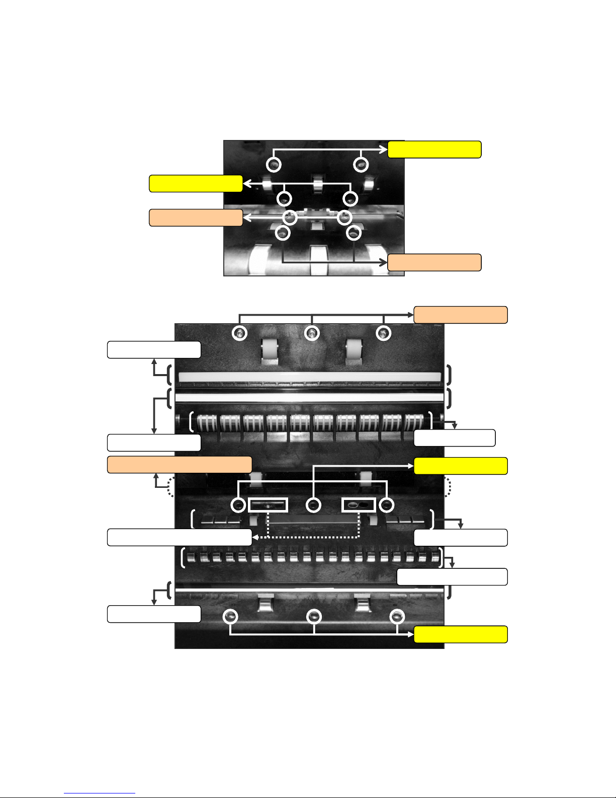
■ Sensors as View
① VIEW A
② VIEW B
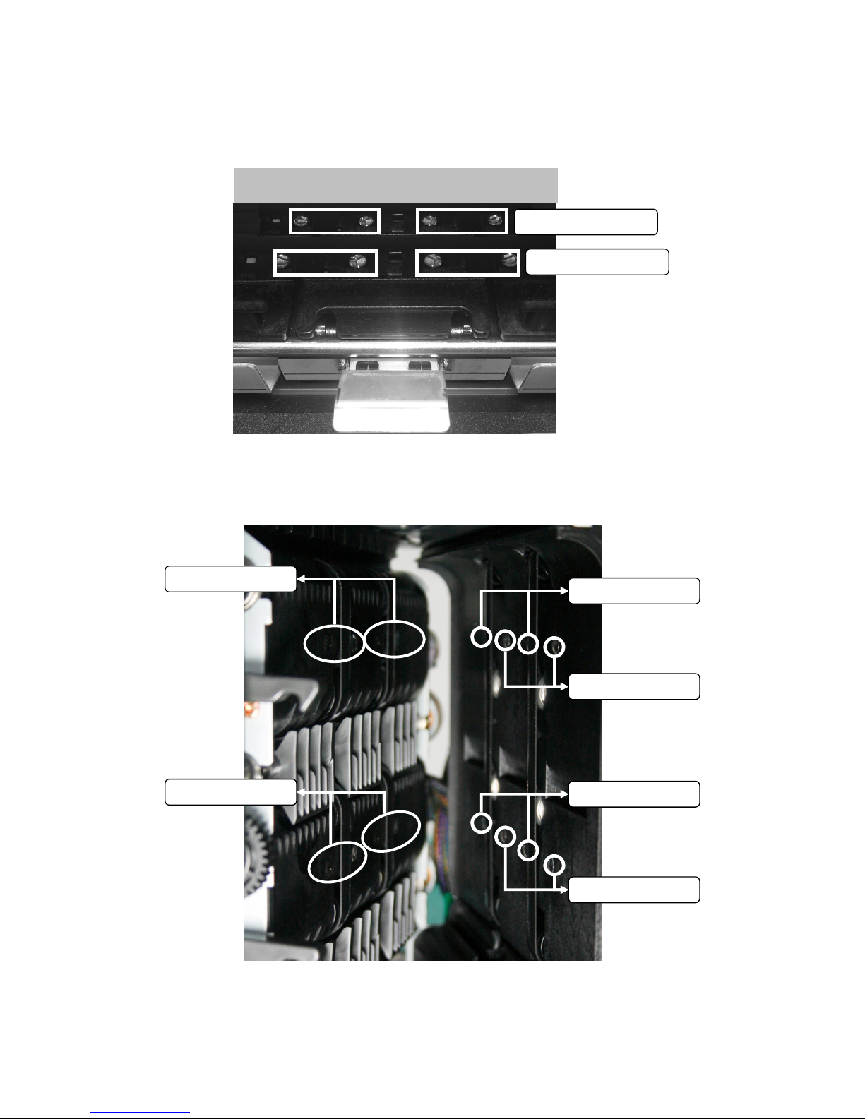
RP2 Trans. sensors
RP1 Trans. sensors
RP2 Rcv. sensors
RP1 Rcv. sensors
RP3 Trans. sensors
RP3 Rcv. sensors
RP4 Trans. sensors
MR Array & Singles
IR Trans. sensor
OPT CIS sensor
Roller Detect Tape
RP4 Rcv. Sensors & UV sensors
CIS sensor
UV sensors (Left/ Right)
Ass’y Block Tape Detect
Page 21
21
③ VIEW C
④ VIEW D
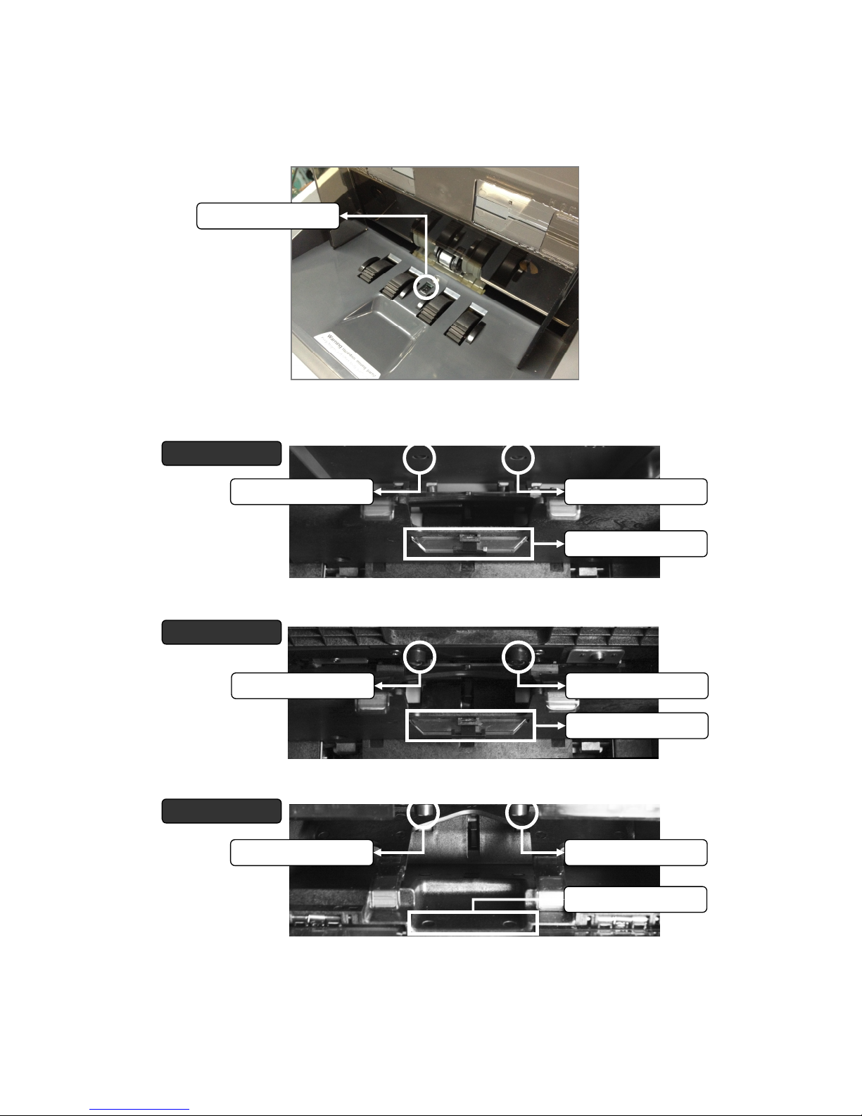
Prism for RP6 sensors
Prism for RP5 sensors
Trans. and Rcv. Sensors (Hidden)
RP8 Trans. sensors
RP8 Rcv. sensors
RP7 Trans. sensors
RP7 Rcv. sensors
Prisms of RP7
Prisms of RP8
Page 22
22
⑤ VIEW E
⑥ VIEW F
Hopper sensor
Stacker 1
Stacker 2
Reject Pocket
Stacker1 Trans. sensor
Stacker1 Rcv. sensor
Prism of Stacker1
Stacker2 Trans. sensor
Reject Trans. sensor
Stacker2 Rcv. sensor
Prism of Stacker2
Stacker2 Rcv. sensor
Prism of Reject
Page 23
23
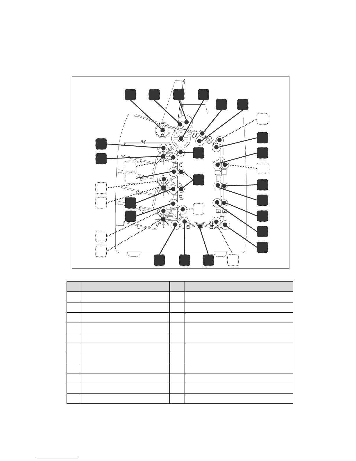
2.3.2. ROLLERS
No
Part Name No
Part Name
1 ROLLER_PICKUP 12 ROLLER_FEED_MG
2 ROLLER_PRESS 13 CROWN_EXIT_ROLLER
3 ROLLER_SEPARATE 14 CROWN_TRANSFER_ROLLER_PINCH_S
4 ROLLER_ADF 15 CROWN_TRANSFER_ROLLER_PINCH
5 ROLLER_PINCH_FEED 16 CROWN_TRANSFER_ROLLER
6 FEED_ROLLER_A 17 CROWN_EXIT_ROLLER
7 FEED_ROLLER_B 18 CROWN_EXIT_ROLLER_PINCH_A
8 FEED_ROLLER 19 ROLLER_PIHCN_MR
9 MOUDLE_ROLLER_T 20 CROWN_EXIT_ROLLER_PINCH_1
10 ROLLER_DETECT_TAPE_S3000 21 ROLLER_FEED_OUTLET
11 ROLLER_PINCH_MR 22 ROLLER_PINCH_TRANS_POCKET
1
2 3
4
5
6
5
7
8
5
9
10
11
12
13
13
13
14
16 15
17
18
19
18
20
21
22
21
22
21
22
17
Page 24
24
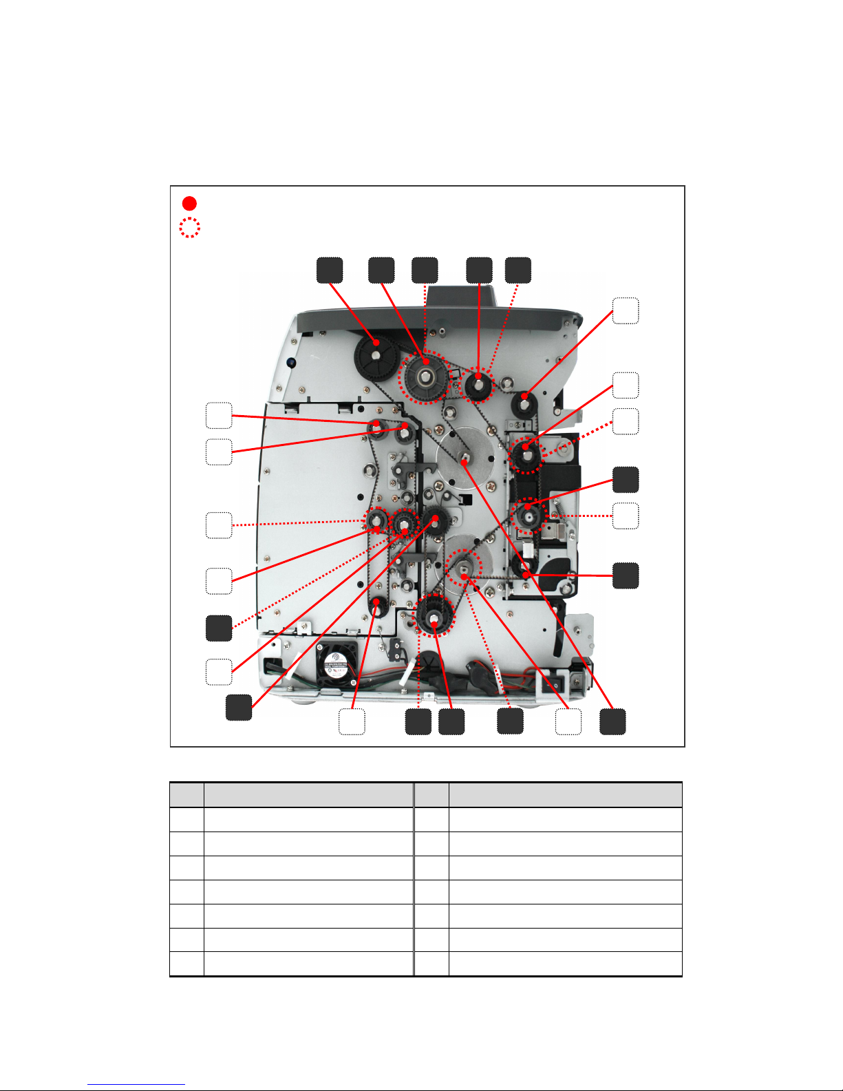
2.3.3. PULLEY
No
Part Name No
Part Name
1 PULLEY_ADF_V_S3M-40 8 PULLEY_STEP_MOTOR_S3M_15
2 PULLEY_ADF_CLUTCH40 9 PULLEY_S3M_18
3 PULLEY_ADF_S3M-40 10 PULLEY_S3M_16
4 PULLEY_FEED 11 PULLEY_FEED_4_V_S3M-32
5 PULLEY_FEED_1_V_S2M-24 12 GEAR_M08_T35-2
6 PULLEY_S3M-20 13 GEAR_M08_T35
7 PULLEY_FEED_1_V_S2M-24
: Forward part,
: Backward part
1
2 3 4 5
5
5
5
6
6
7
8
8 10 11 4
6
12
6
13
6
4
6
9
Page 25
25
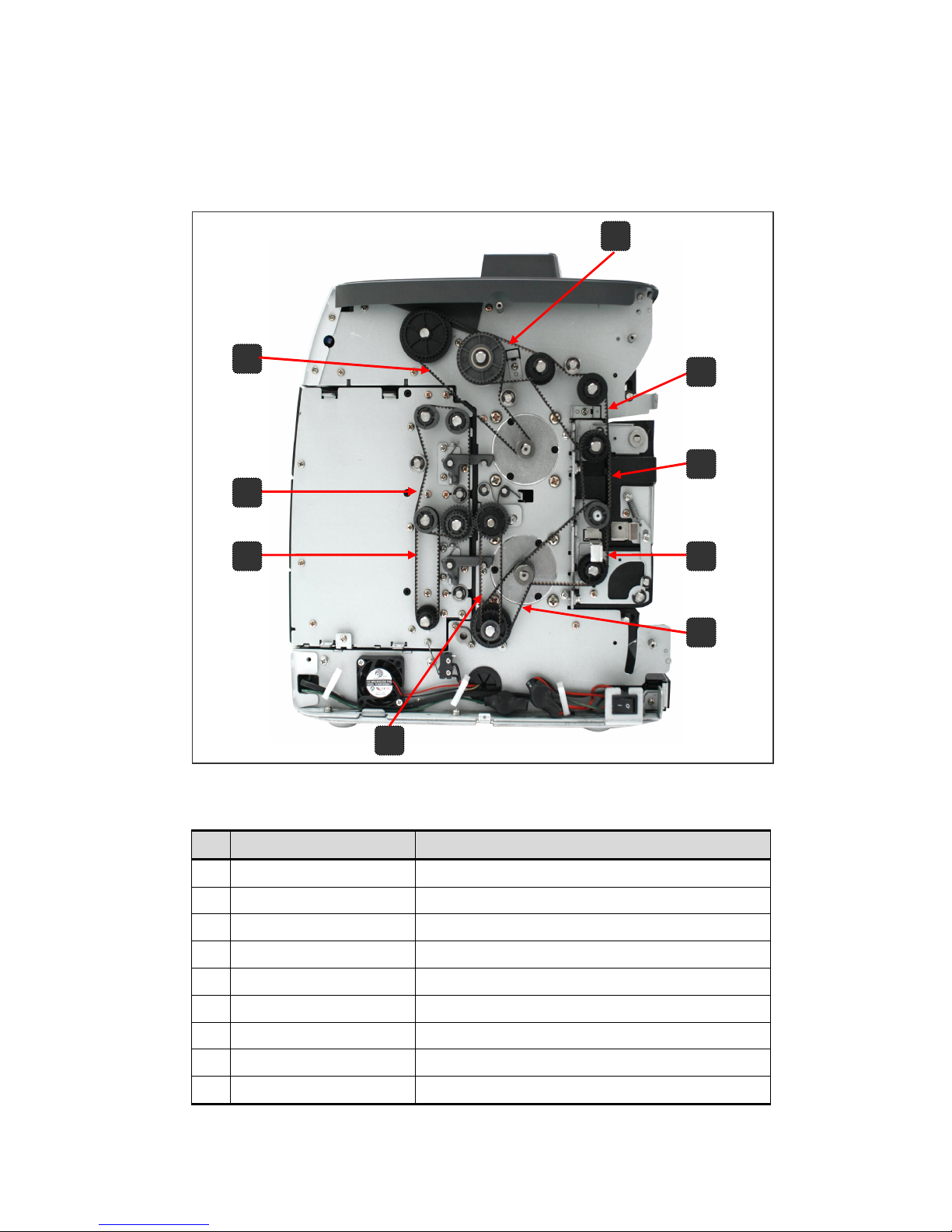
2.3.4. TIMING BELTS
No
Belt Code Part Name
1 S3M 345 BELT ADF PICK MOTOR
2 S3M 186 BELT ADF LINK
3 S3M 237 BELT DETECT 1
4 S3M 171 BELT DETECT 2
5 S3M 213 BELT DETECT 3
6 S3M 180 BELT MOTOR-2
7 S3M 216 BELT GEAR LINK
8 S3M 273 BELT OUTLET
9 S3M 213 BELT OUTLET SMALL
1
2 5 7 3 4
6
9
8
Page 26
26
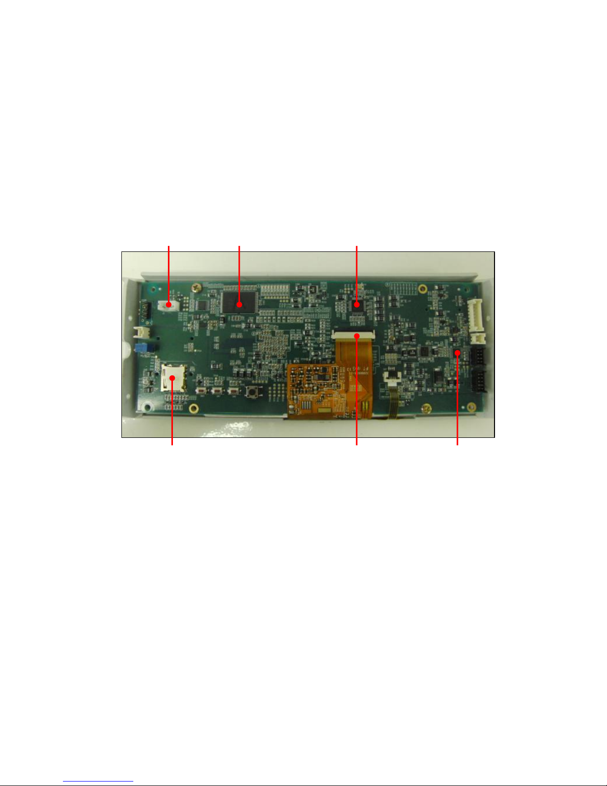
2.4.0. Function of each Board
■ Main Board
The part controlling on Main Board is as follows
Operation Panels
: LCD displaying, Audio Codec, Hopper sensor, SD Card, USB
SDRAM
Hopper Sensor
Audio Codec
SD Card Slot
LCD Conn.
UART
Page 27
27
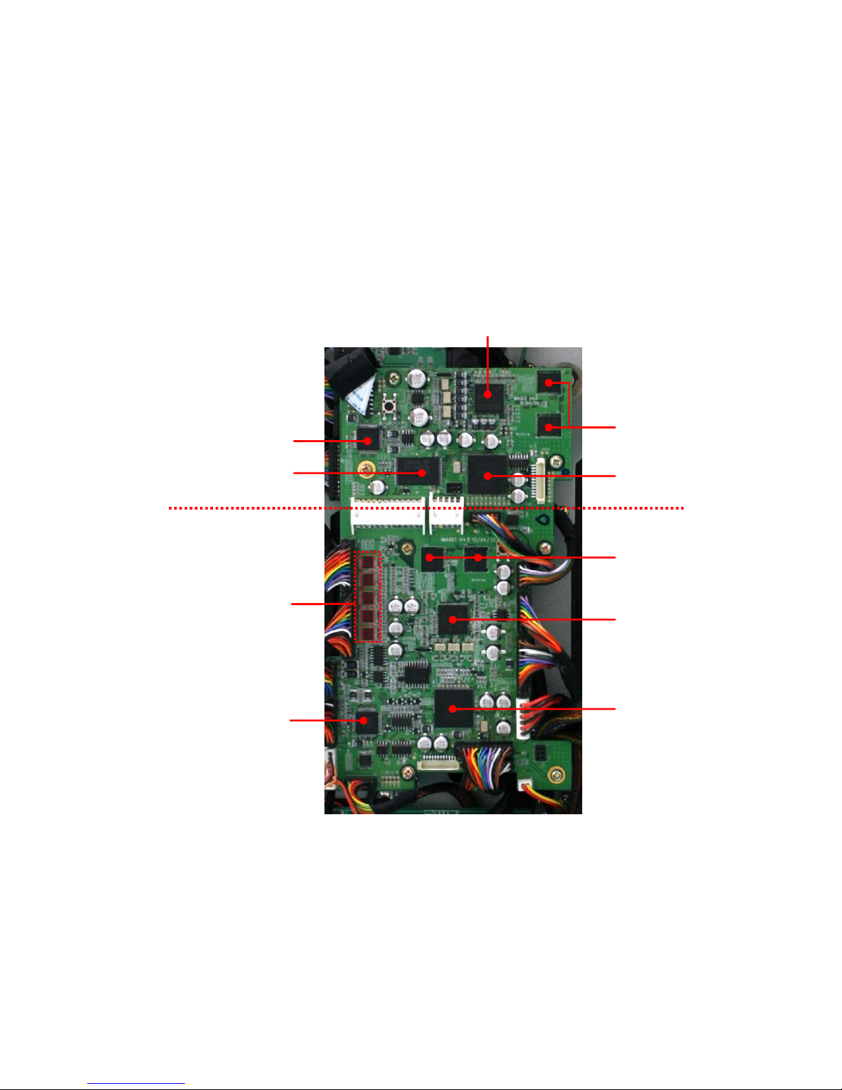
IMAGE 2 (OPTION)
■ Image Board
The part controlling on Image board as follows
Control & Processing
Counterfeit Detection: UV, MR Array, MRS L/R. IR
Fitness: CIS, CAP (Tape)
Positing sensors: RP 1 ~ 8
Output Port: Serial, Parallel, USB, RJ11 (Customer Display)
CPU
PLD
SDRAM
Image Processor
Flash
MUX
Image Processor
SDRAM
CPU
PLD
IMAGE 1
Page 28
28
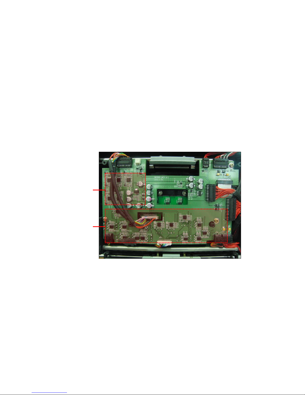
■ MTU Board (‘CF AMP’ & ‘CAP AMP’)
MTU: Magnetic, Tape, Ultraviolet
The part controlling on MTU board is CF Amp.(for Magnetic sensor) and Cap Amp.(for tape detection)
CF AMP
Input: MR array (6 channels), MRS L/R
Role & Output: Amplifying MR signal and transferring it to the Image Board.
CAP AMP
Amplifying the CAP sensor signal and transferring it to the Image Board
CAP AMP
CF AMP
Page 29
29
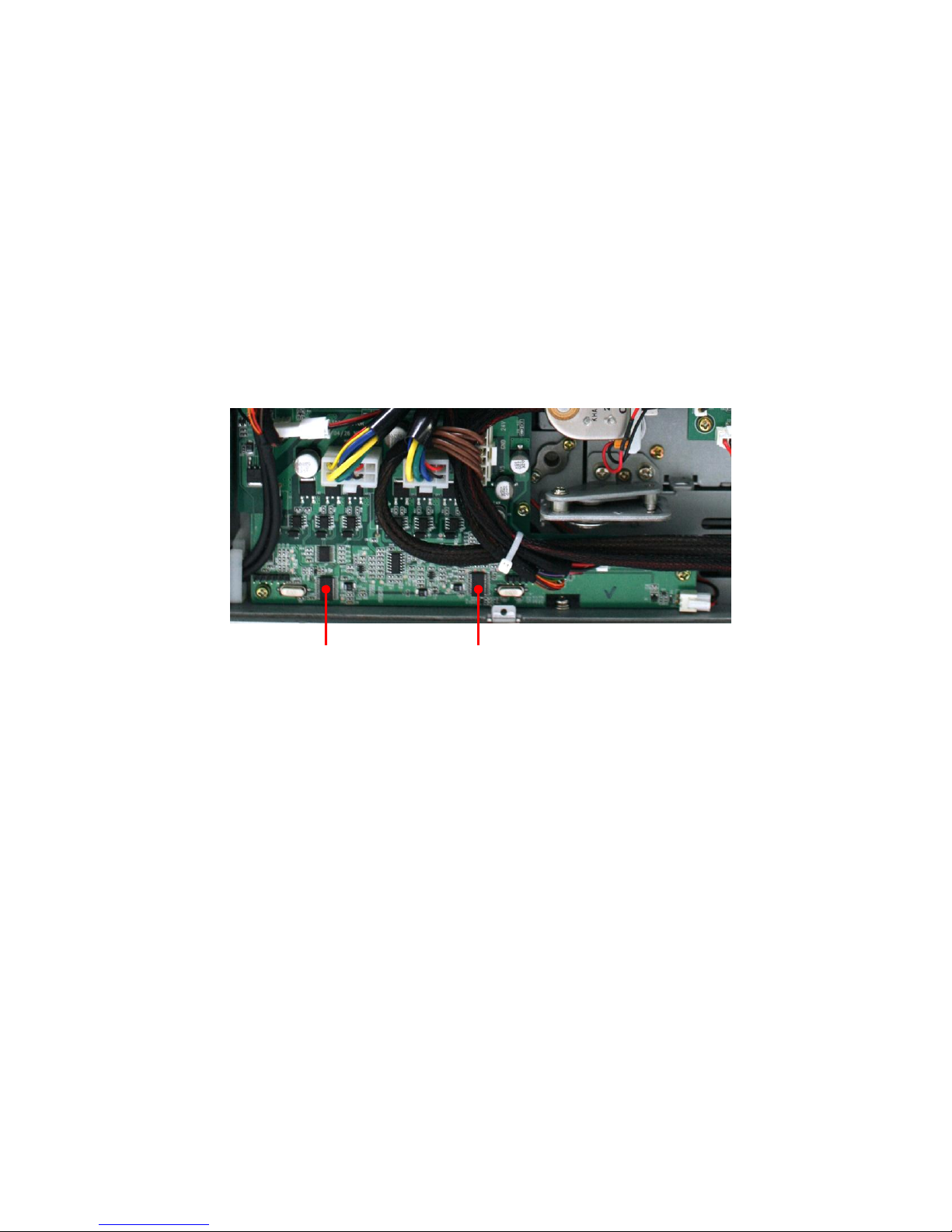
■ Motor Board
The part controlling on Motor Board is as follows
Operation Panels
Main Motor
Pickup Motor
Fan
Main Motor
Pickup Motor
Page 30
30
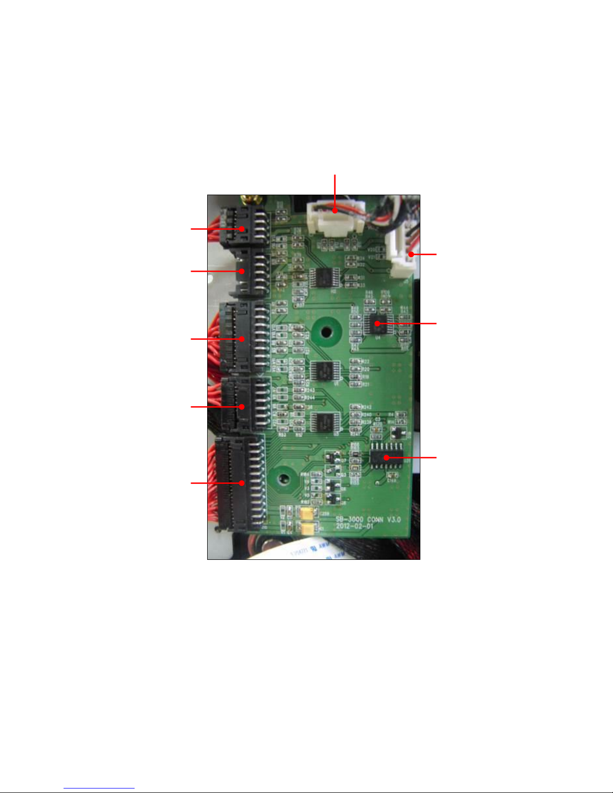
■ Connector Board
RP1, 2 Tran.
RP1, 2 Rcv.
Comparator
AMP
RP 7
RP 8
RP 5, 6
RP 3 Rcv.
& IR Trans
Image Board
Page 31
31
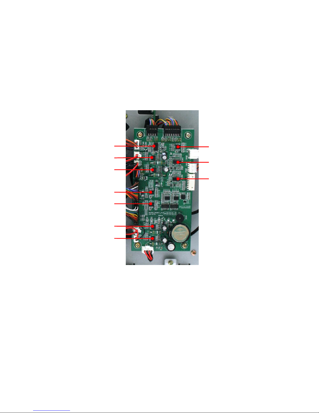
■ Pocket Board
The part controlling on Pocket Board is as follows
Control & Processing
Operation Panel: Stacker 1, 2 and Reject Pocket
Sensors: Stacker 1, Stacker 2, Reject Pocket, Stacker Overflow, Stacker Hi & Low
Geared Motor 1
Comparator
Stacker 2 Sensor
Reject Pocket Sensor
Solenoid 1
Stacker 1 Sensor
Stacker Hi & Low Sensor
Stacker 1 & 2 Reject Sensor
Geared Motor 2
Solenoid 2
Page 32
32
3.0.0. OVERALL OF CONTROL
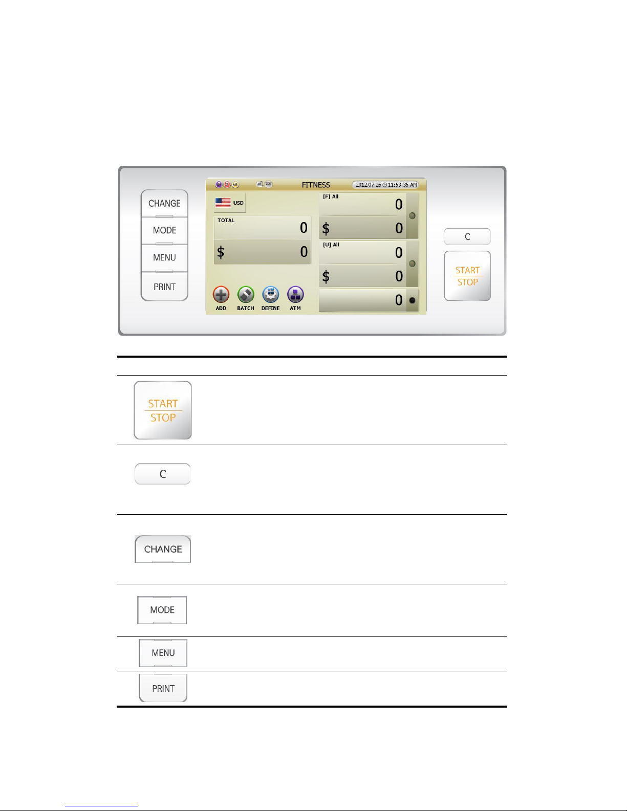
3.1.0. OVERALL OF CONTROL PANEL
Indication Description
- Manually START (when manual starting is set)
- Emergency STOP & START while counting.
- Save or set the mode
- This key means ‘OK’ and ‘YES.’
- CLEAR the count result or go back to previous stage.
- CANCEL the present setting.
- User can remove the jammed notes.
- This key means ‘Cancel’, ‘Close’ and ‘No.’
- To change the display form of count result.
- To change the activated icon one by one
- This key means CHANGE something.
(In case of using [CHANGE] key, will be referred at {Help} part)
- To change the WORKING MODE.
(FITNESS, COUNT, FACE, ORIENT, ISSUE, DISPENSE and OCR)
- User can enter ADMIN Menu from MENU.
- To enter Setting Menu (User can set various Parameters).
- To escape from Setting Menu.
- To print the counted result.
(FIG 3-03)
Page 33
33
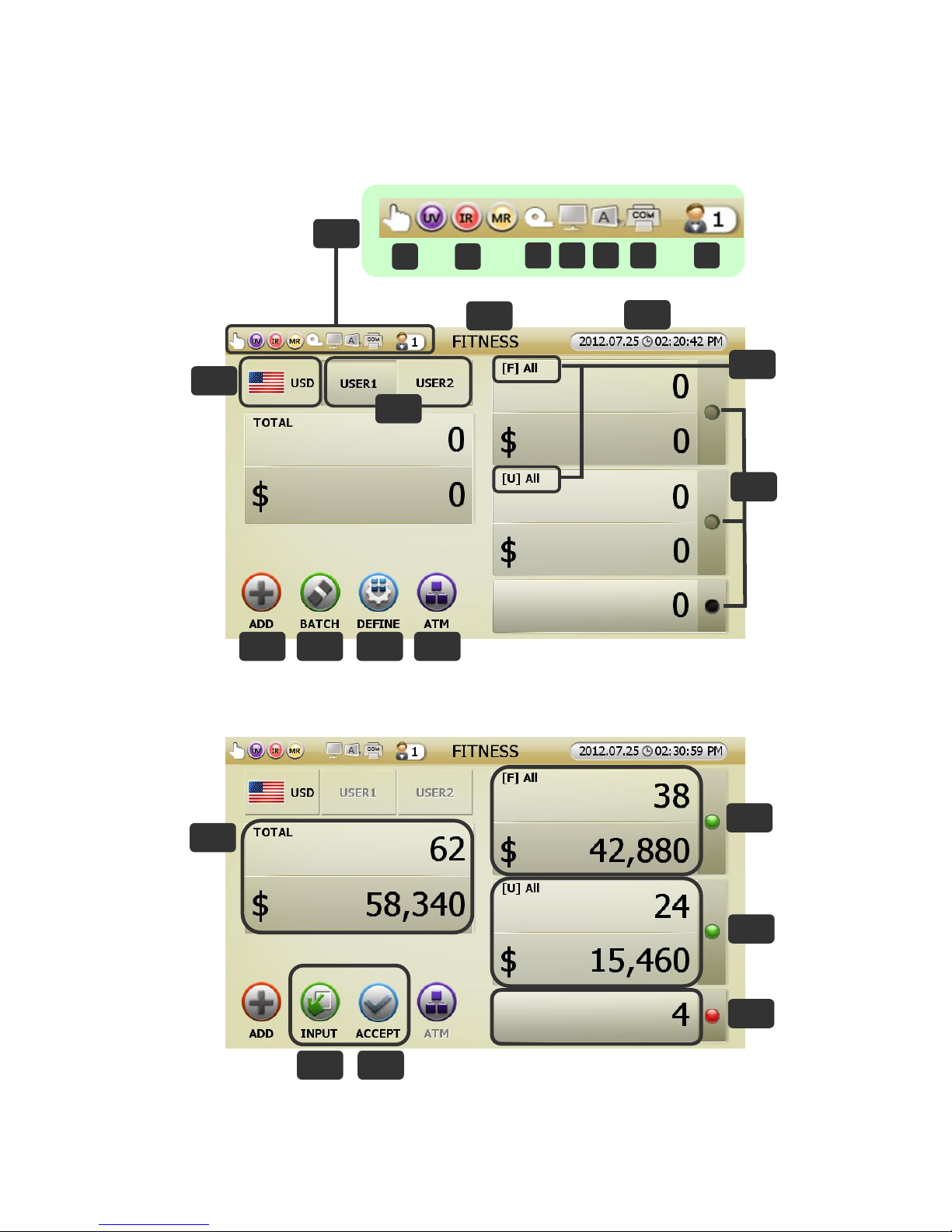
3.2.0. OVERALL OF TOUCH SCREEN
[Before counting]
[After counting]
(FIG 3-05)
14
15 16
17
12
13
(FIG 3-04)
4
6 7 8 9
1
2
3
1-1
1-2
1-3 1-4 1-5 1-6
1-7
5
10
11
Page 34
34
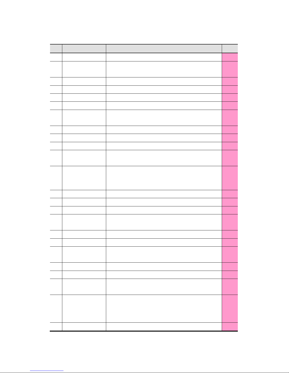
No.
Name Description Note
1
Indicators
1-1
Start mode
To show auto start or manual start
Auto start is Default and in case of manual start this appears
P44
1-2
Counterfeit To show On/Off of UV/ IR/ MR Sensors P52
1-3
Tape Sensor To show Tape Sensor On/Off except for in Fitness Mode P52
1-4
PC Control To show SB-3000 is controlled by PC or not
1-5
Customer Display To show Customer display is on operation (Display A, B) P48
1-6
Print Port
To show the using Print Port
[COM port, USB port, COM port (USB in P-OCR mode)]
P47
1-7
User Define Mode To show User Define Mode P37
2
Present Working Mode To show present Working Mode P29
3
Date & Time To show Date & Time P45
4
Present Currency
To show present currency. User can change currency when every
touch
P19
5
Concurrent User
2 persons can use SB-3000 at the same time
To set the user, touch the alternative button
Double Touch can change the user
P52
6
ADD To show ADD is On/Off P39
7
Batch Touch Batch button to set Batch function P40
8
Define User can define his/her own setting (Max. 8 settings) P37
9
Sub Mode
Indicates [Sub Mode] icon and
Activated in Fitness Mode & OCR Mode.
P30
P35
10
Pocket arrange display To show the kinds of notes which will be stacked
11
Pocket LED To show each pocket is empty/full
12
INPUT
To correct the count result. User can add the amount of Uncounted
notes or coins manually.
P22
13
ACCEPT Count result will be added to Grand Total P23
14
Total The Total of Stacker 1 and Stacker 2
15
Stacker 1
Stacker Pocket1 count result. Touch this button to see Detail
view(User can see Stacker1 & Stacker2 count results)
16
Stacker2
Stacker Pocket 2 count result. Touch this button to see Detail view
(User can see Stacker1 & Stacker2 count results. If Stacker2 is set for
Unfit, it displays Unfit Reason.)
17
Reject Reject Pocket count result. Touch this button to see Detail view.
Page 35
35
4.0.0. PREPARATION OF OPERATION
4.1.0. Banknotes Preparation
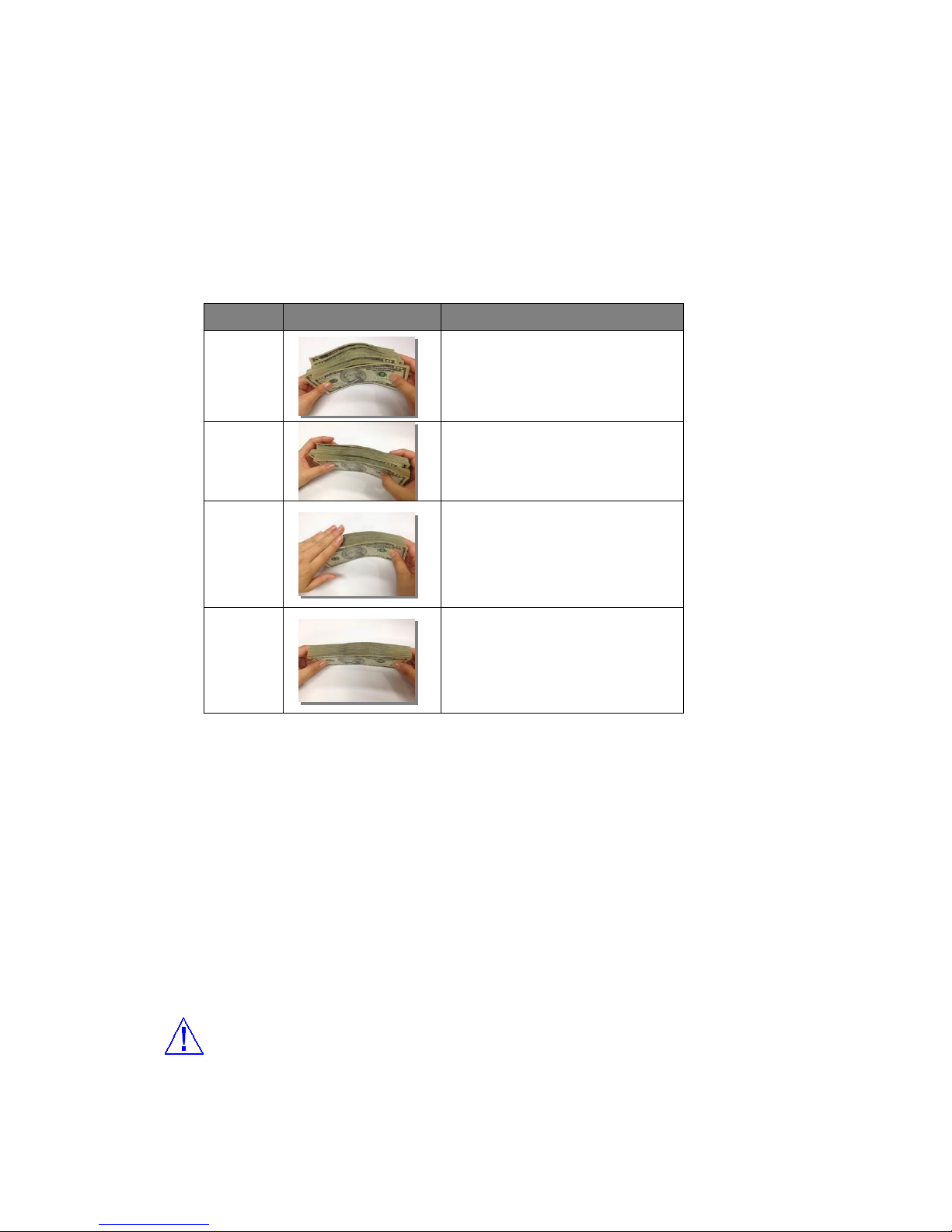
[PROCEDURE]
Step Figure Description
1 Step
Prepare the banknotes under the
condition of below ⒜
2 Step
Put one side of banknotes on the table
and align them.
3 Step
And make them square horizontally
and vertically.
4 Step
Now the banknotes are ready.
⒜ Proper banknote preparation improves the banknote processing and increase the throughout.
Before placing the banknotes into the Hopper,
Please sort out any banknotes as following
- Wet notes
- Excessively dirty/ spoiled notes
- Extreme damaged notes
- Severely folded/ curled notes etc.
These banknotes as above should be placed aside and be sorted by manual.
[CAUTION]
YOU HAVE TO MAKE SURE THAT THERE ARE NO CLIPS, BANDS OR SIMILAR FOREIGN
MATERIALS ON THE BANKNOTES. SOMETIMES IT CAUSES MALFUNCTION OF THE
MACHINE.
(FIG 4-01
)
Page 36
36
4.2.0. HOW TO ADJUST THE BILL GUIDE HOPPER
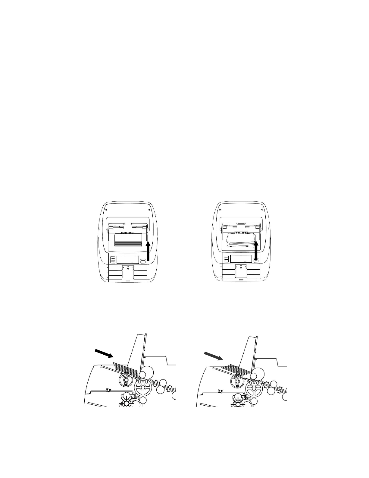
Before putting the banknotes into the Hopper, User needs to adjust the Bill Guide. Users should make sure
that there is enough room on the sides for the banknotes to be pulled in the Hopper easily (banknote
length + approximately 5mm)
4.3.0. How to place banknotes into the Hopper
It is very important to place the banknotes on the hopper correctly because recognition performance of the
banknotes is highly affected by the arrangement of the banknotes. And the number of the rejected notes
can be increased when they are not arranged and placed properly. Refer to the pictures for the correct
placement of the banknotes.
(FIG 4-02) (FIG 4-03)
(FIG 4-04) (FIG 4-05)
(Good) (No good)
(Good) (No good)
Page 37

37
4.4.0. COUNTING
In AUTO mode, SB-3000 starts to count the bill automatically as it detects the existence of the banknotes
in the hopper. In MANUAL mode, the machine will start to count the banknotes only if the banknotes are
placed into the hopper and START key is pressed. While counting, the machine will display the number of
the banknotes on LCD display and it stops working when it meets the conditions described as below;
No bills in the hopper
Stacker is full.
Rejecter is full.
The number of the bills counted is the same as the batch number to be set in BATCH function.
Errors have occurred.
If an error is occurred during operation and the machine stops, then an error message will be displayed.
To clear the error, press “C” key. The machine will try to solve the problem automatically, but if it fails to
clear a jam or there are some other mechanical errors, open the rear door A (rear top) or rear door B (rear
middle or rear bottom) and get rid of jammed banknotes and close the cover correctly. Then the machine
can clear error message automatically.
(Stop in operation)
Press [START/STOP] button to stop operation for an instant while the machine is operating.
If you want to count continuously again, press [START/STOP] button.
Stop in operation
Please START button to stop operation while the machine is counting.
If you want to count continuously again, press [START/STOP] button.
Page 38
38
5.0.0. BASIC OPERATION
5.1.0. PROCEDURE OF OPERATION
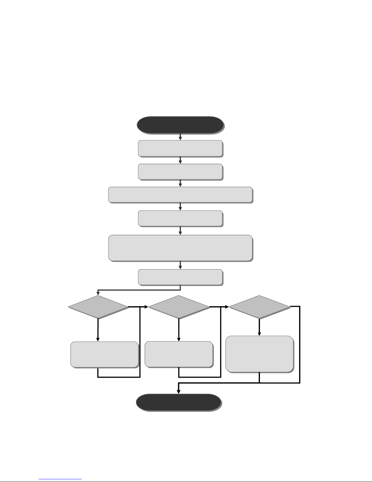
5.1.1. FLOW CHART
Operation Start
Banknotes Preparation ▶ Page
Bill Guide Adjusting ▶ Page 16
Setting of Currency, Working Mode, Pocket, etc ▶ Page 19
Put the notes on Hopper ▶ Page
Start Counting
In case of manual start, press [START/STOP] key
Close Counting
Operation End
NO
INPUT ACCEPT?
Add the count result to GT
▶ Page 23
PRINT?
Print Total/ the Day Total/
Grand Total
▶ Page 25
YES
YES
YES
NO
NO
Correct the count result
▶ Page 22
Page 39
39
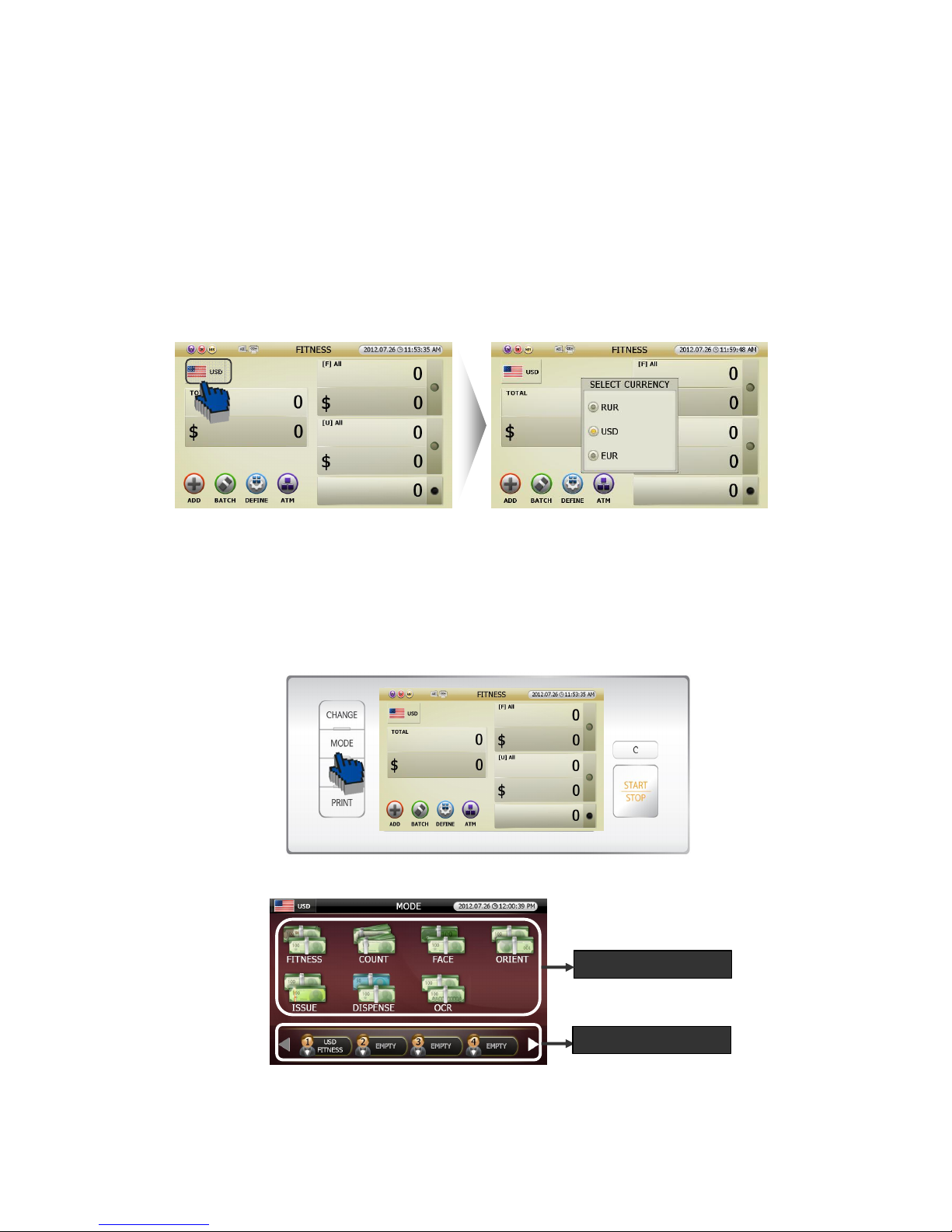
5.1.2. Currency Selection
In order to change the Currency, touch [CURRENCY] icon.
If you need to purchase more software to handle different currencies, PLESASE CONSULT WITH
YOUR DEALER.
5.1.3. Working Mode Setting
Can set working mode as below.
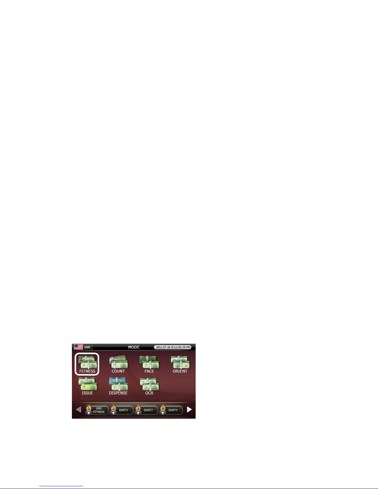
[1] Pressing [MODE] button in initial screen (FIG 5-01), the screen will change Mode screen like below
(FIG 5-03).
[2] MODE selection screen displays 2 windows like below (FIG 5-03).
(FIG 5-01)
(FIG 5-02)
(FIG 5-03)
① Basic Working Mode
② User Define Mode
Page 40
40
① Basic Working Mode: Fitness, Count, Face, Orient, Issue, Dispense, OCR Mode
② User Define Mode: User can set up Max 8 modes for his/her usual or specific purpose.
[3] Can select the ‘Working Mode’ by touching the icon.
[4] The screen will change into initial screen of wokring mode selected
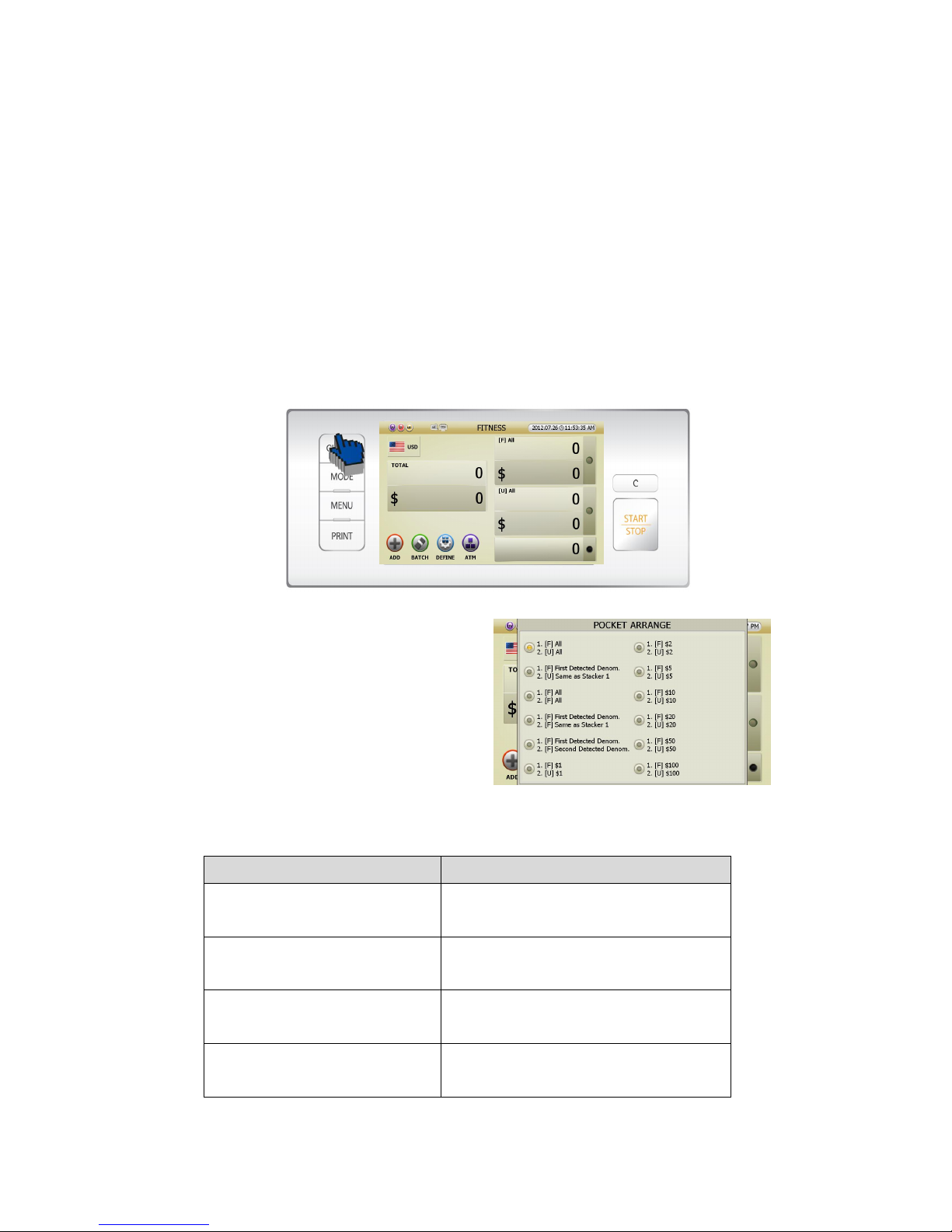
Can allocate stacker and reject pockets in Basic Working Mode like below.
[1] If user press [CHANGE] button in initial screen (FIG 5-01), the display will change like below (FIG 5-04).
[2] Can select the pocket allocation in ‘POCKET
ARRANGE’ list by touching the title
[3] The screen will change into initial screen
[4] Pocket Arrange list explanation
Pocket Arrange indication Stacker 1, Stacker 2 explanations
1. [F] All
2. [U] All
Stacker 1: All the Fit notes
Stacker 2: All the Unfit notes
1. [F] First Detected Denom.
2. [U] Same as Stacker 1
Stacker 1: First detected Fit Denom. notes
Stacker 2: Same as Stacker 1 notes but Unfit
1. [F] All
2. [F] All
Stacker 1: All the Fit notes
Stacker 2: All the Fit notes
1. [F] First Detected Denom.
2. [F] Same as Stacker 1
Stacker 1: First detected Fit Denom. notes
Stacker 2: Same as Stacker 1
(FIG 5-04)
Page 41
41
1. [F] First Detected Denom.
2. [F] Second Detected Denom.
Stacker 1: First detected Fit Denom. notes
Stacker 2: Second detected Fit Denom. notes
1. [F] $1
2. [U] $1
Stacker 1: Fit $1
Stacker 2: Unfit $1
1. [F] $2
2. [U] $2
Stacker 1: Fit $2
Stacker 2: Unfit $2
1. [F] $5
2. [U] $5
Stacker 1: Fit $5
Stacker 2: Unfit $5
1. [F] $10
2. [U] $10
Stacker 1: Fit $10
Stacker 2: Unfit $10
1. [F] $20
2. [U] $20
Stacker 1: Fit $20
Stacker 2: Unfit $20
1. [F] $50
2. [U] $50
Stacker 1: Fit $50
Stacker 2: Unfit $50
1. [F] $100
2. [U] $100
Stacker 1: Fit $100
Stacker 2: Unfit $100
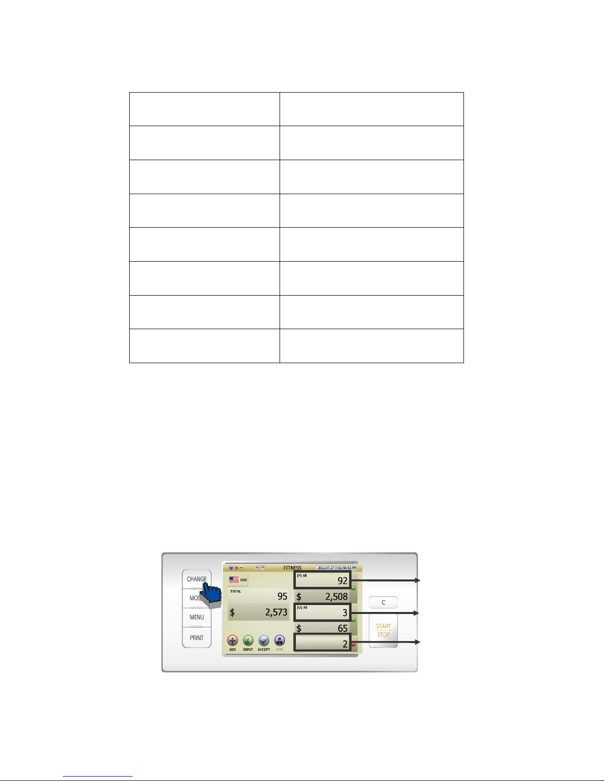
5.1.4 Counting Result Confirmation
Remark) Below picture are under the condition of [Fitness Mode] that Stacker 1 was [F] All and Stacker 2
was [U] All.
1 Counting Result Confirmation in Counting Result screen
[1] Pressing [CHANGE] button consecutively after counting, can see 3 screens like below pictures.
ⓐ
ⓑ
ⓒ
Page 42
42
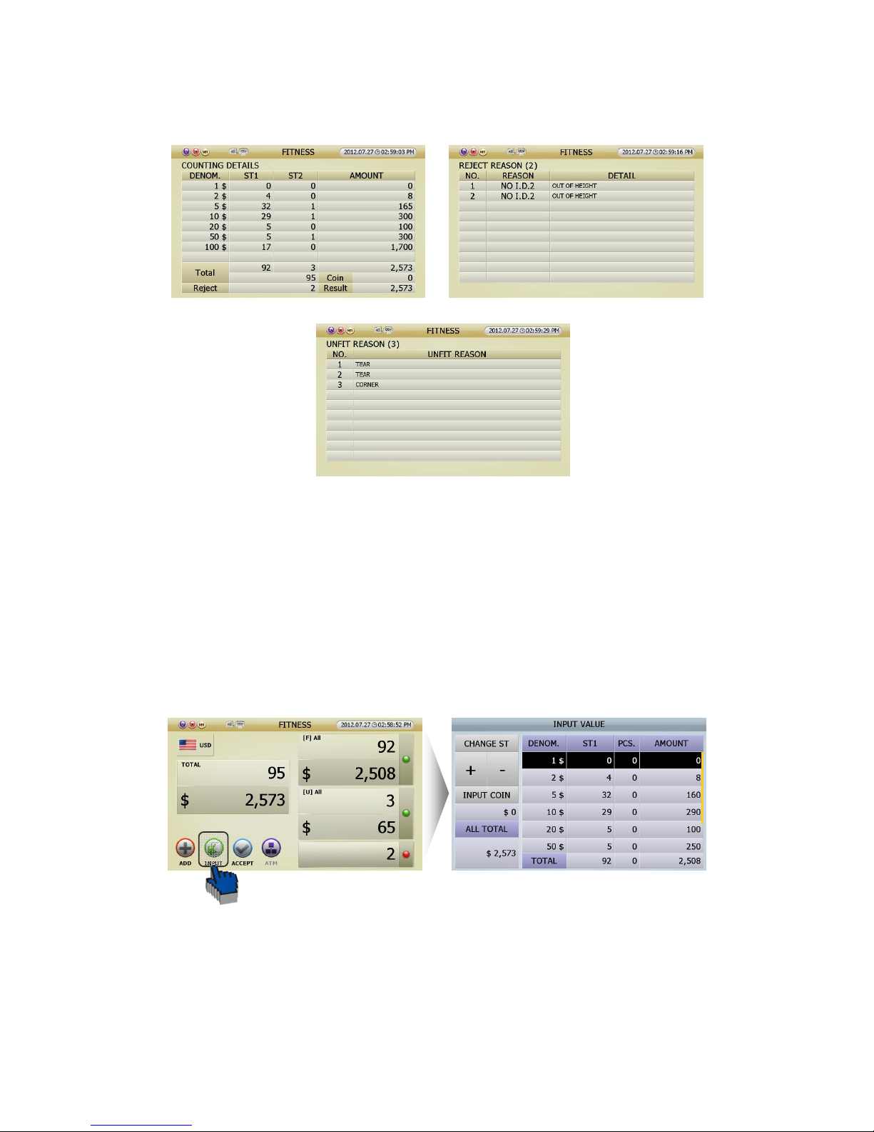
[2] If you touch the section of result in screen (fig 5-10), the screen will show specific results.
① If you touch the section (ⓐ) in Stacker 1, the screen will show the ‘COUNTING DETAILS’ (FIG 5-11).
② If your touch the section (ⓑ) in Stacker 2, the screen will show the ‘UNFIT REASON’ (FIG 5-13).
③ If your touch the section (ⓒ) in Reject, the screen will show the ‘Reject Reason’ (FIG 5-12).
2 [INPUT] function is designed to correct the counting result. You can add the amount of uncounted notes
(because of seriously damaged notes) or coins manually. If user touch [INPUT] icon in counting result
screen (FIG 5-10), You can see INPUT VALUE screen (FIG 5-14) and can correct the count result minutely.
(FIG 5-10)
(FIG 5-11)
(FIG 5-12)
(FIG 5-13)
(FIG 5-
10)
(FIG 5-14)
(FIG 5-10)
Page 43
43
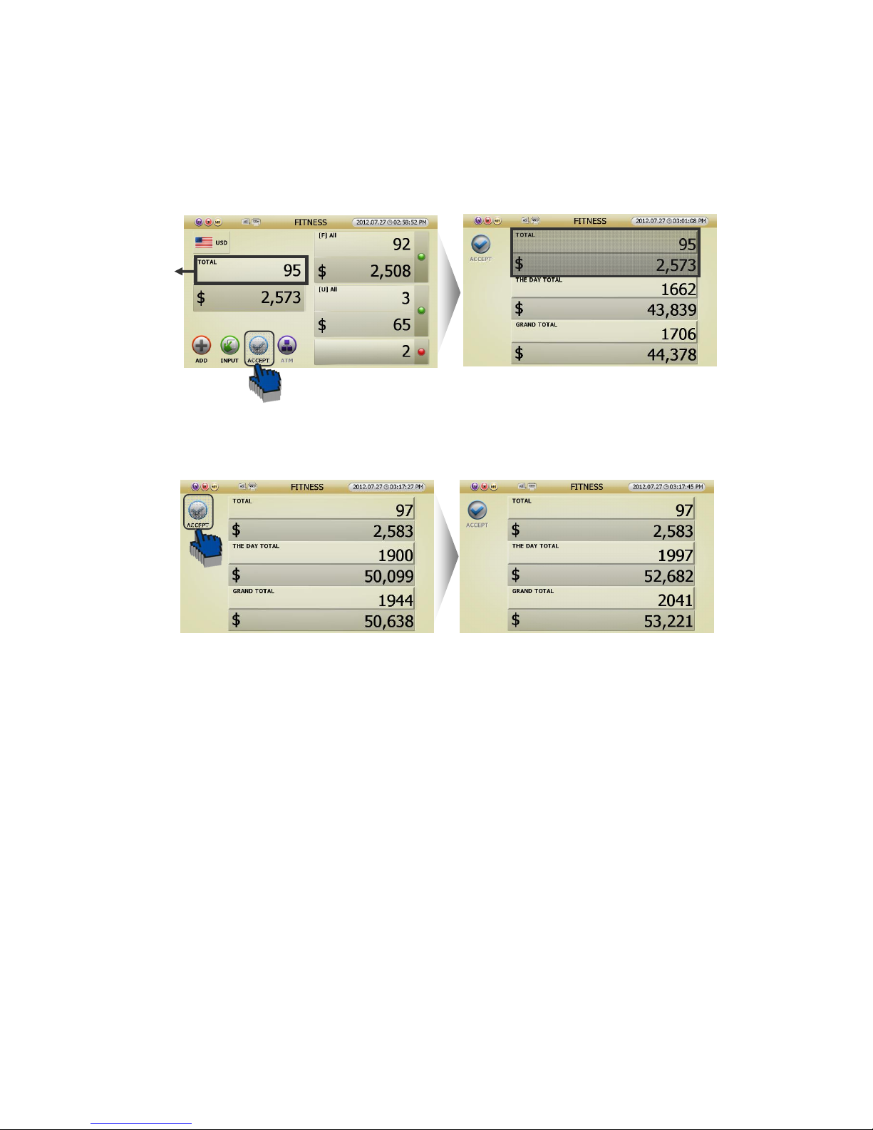
3 [ACCEPT] function means that user can add the counting result to Grand Total.
This is how to use [ACCEPT] function.
[1] If user touch [ACCEPT] icon in counting result screen,
[2] Or If you touch ⓓ section in counting result screen, can see the GRAND TOTAL Screen (FIG 5-16).
After you check the screen, touch the [ACCEPT] icon. Then the counting result will be added to GRAND
TOTAL.
Caution) The counting result can be [Accepted] only in [ADD] function-Off after taken off the notes
in the Pockets or Hopper
[3] Auto Accept
If you want, can set ‘Auto Accept.’ (Refering to page 44)
But, though it is set [Auto Accept], it is switched manually when Reject occurs on the counting
5.1.5 Grand Total (GT)
Grand Total means the accumulation of counted notes that user accepted. Namely, if you touch [ACCEPT]
icon after counting, the result will be added to GRAND TOTAL.
SB-3000 can show 3 kinds of count result. One is present ‘Total,’ another is the ‘Day Total,’ and the other is
‘Grand Total.’
(FIG 5-15)
(FIG 5-16) (FIG 5-17)
ⓓ
(FIG 5-10)
Page 44
44
1. There are 2 ways how to calculate Grand Total (Referring to page 23).
[1] Can touch [ACCEPT] icon in counting result screen (FIG 5-04),
[2] Or if you touch ‘total’ area in counting result screen (FIG 5-04), can see GRAND TOTAL screen (FIG 5-
16). After you check the screen, touch the [ACCEPT] icon. Then the counting result will be added to
GRAND TOTAL.
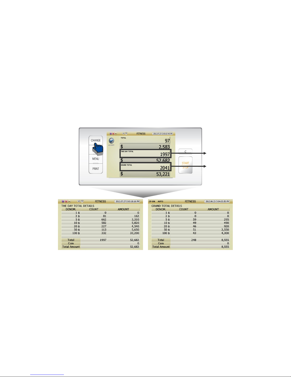
2. Can check THE DAY TOTAL DETAILS and GRAND TOTLA DETAILS by touching the section in Grand
Total Screen (FIG 5-17).
[1] Press [CHANGE] button, and can see THE DAY TOTAL DETAIL screen (FIG 5-18) and GRAND TOTAL
DETAIL screen (FIG 5-19).
[2] Touch the screen section in GRAND TOTAL screen (FIG 5-17), can enter detail stages.
① If you touch the section (ⓐ) in Stacker 1, can enter THE DAY TOTAL DETAILS screen (FIG 5-18).
② If your touch the section (ⓑ)
in
Stacker 2, can enter GRAND TOTAL DETAILS screen (FIG 5-19).
3. Can control [Grand Total] at ADMIN. MENU. (Referring to page 53)
(FIG 5-18)
(FIG 5-19)
ⓐ
ⓑ
(FIG 5-17)
Page 45
45
(FIG 5-21)
5.1.6 Print
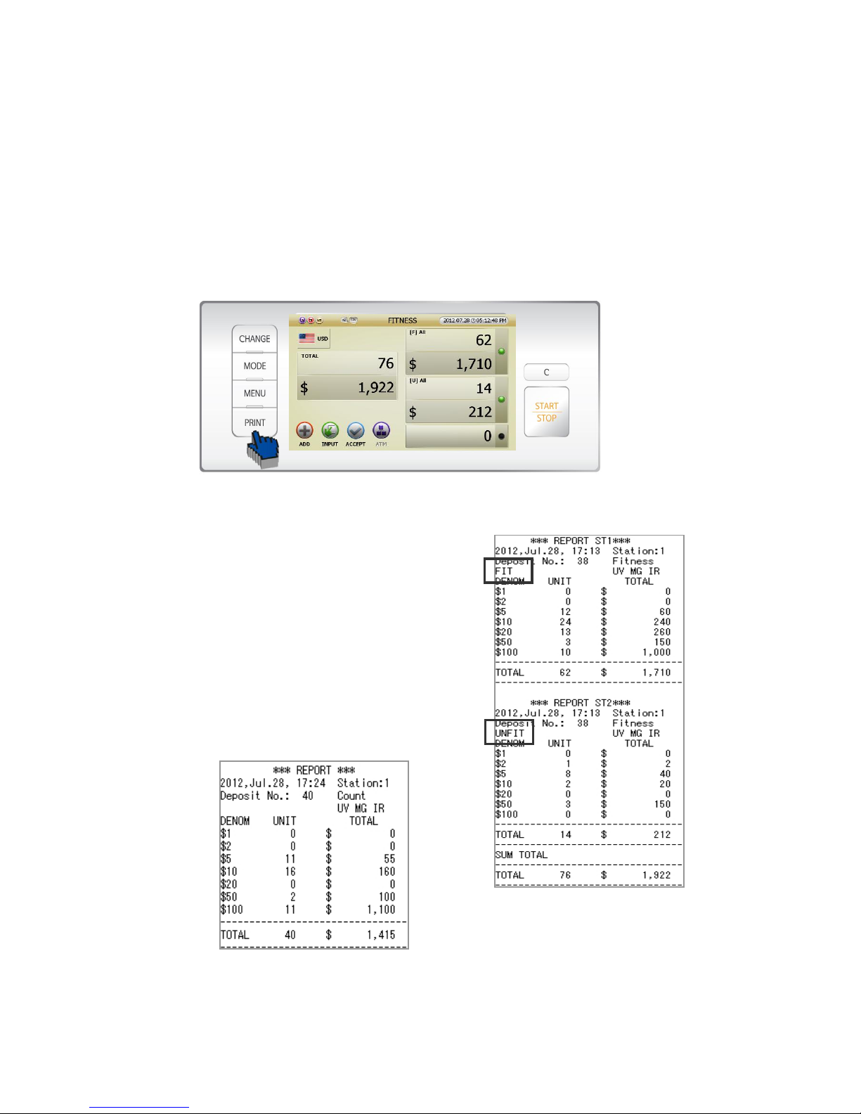
SB-3000 can print out below 3 results.
Present count result /GRAND TOTAL per user/GRAND TOTAL of SB-3000
Present Count Result Printing
Press [Print] Key after counting, and can print out as below.
* Caution) In order to print out, notes in Reject Pocket must be removed.
[1] If Stacker 1 and Stacker 2 are set as [Fit] and [Unfit] under
Fitness mode, the print report will show the result of Stacker1
[Fit] and Stacker 2 [Unfit] like right picture.
[2] If Stacker 1 and Stacker 2 are set as all [Fit], the print report
will show the sum of counting.
[3] If it is not under Fitness mode, the print report will show
the sum of counting.
(FIG 5-22)
(FIG 5-20)
Page 46
46
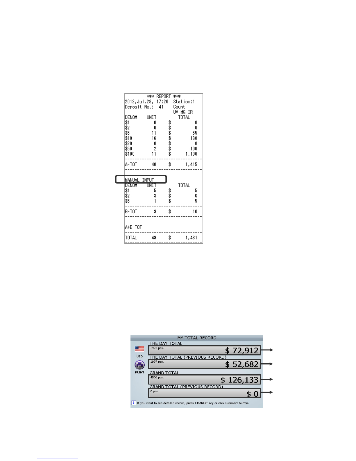
[4] In case you wants to correct the counting result by [INPUT] function (Referring to page 22).
If you print out the corrected counting result, the print report shows the ‘Manual Input’ separately and
shows the sum of counting below the ‘Manual Input.’
Grand Total Print per user
Up to 8 users can count banknotes with one SB-3000. And each user can print out his/her own GRAND
TOTAL.
1. Can check your own counting result at MY TOTAL RECORD in USER MENU.
(FIG 5-23)
(FIG 5-24)
ⓐ
ⓑ
ⓒ
ⓓ
Page 47
47
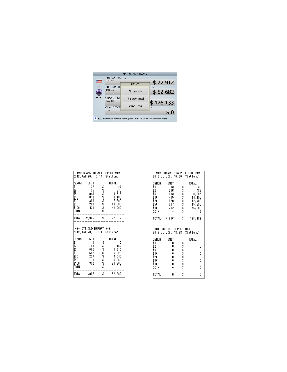
2. How to print out at MY GRAND TOTAL.
[1] Press [PRINT] button or touch [PRINT] icon in MY TOTAL RECORD screen (FIG 5-24), the inner
window will appear. Each cell means as below.
① All records: GRAND TOTAL 1 REPORT/ GT1 OLD REPORT/ GRAND TOTAL 2 REPORT/ GT2 OLD
REPORT
② The Day Total: GRAND TOTAL 1 REPORT/ GT1 OLD REPORT
③ Grand Total: GRAND TOTAL 2 REPORT/ GT2 OLD REPORT
[2] Press [CHANGE] button or touch the each area of sum(ⓐ/ⓑ/ⓒ/ⓓ) in MY TOTAL RECORD screen
(FIG 5-24) for selecting the print item, can press [PRINT] button or touch [PRINT] icon in order to print out.
How to print Grand Total of SB-3000
Can check in ADMIN MENU (Referring to page 55).
(FIG 5-26)
(FIG 5-27)
(FIG 5-25)
Page 48

48
5.1.7 Reject Reasons
No. Display on Screen Meaning
1 NO I.D The machine failed to identify the denomination.
NO I.D.1 Out of height
NO I.D.2 Out of width
NO I.D.3 Out of Skew
NO I.D.4 Can't find top edge
NO I.D.5 Can't find side edge
NO I.D.6 Can't find bottom edge
NO I.D.7 Long distance (SVM)
NO I.D.8 Long distance (Template)
NO I.D.9 White note
NO I.D.10 Last noid
NO I.D.11 OCR error
NO I.D.13 Asymmetrical Error
2 No READ The note was not successfully read
3 OVER RUN The next note was fed too close to the first one.
4 SUSPECT (CF)
The note was suspected to be counterfeit by UV,MR
and IR sensors
5 STAY NOTE The note was not fit to the condition of sorting
6 DOUBLE More than two pieces of notes were fed into machine.
7 CHAIN Chain Error
8 HALF Half Error
9 Over count
The note was in machine after completing the count fit
to the condition of sorting.
(Caution)
If the reject reason is double or chain, the number of the reject note displayed on LCD can be
different with the actual number of notes in the reject pocket.
Page 49
49
5.2.0. Working Mode & Functions
5.2.1. Summary
■ Working Mode
[Basic Working Mode]
● FITNESS Mode: SB-3000 can count and sort Fit Note from Unfit Note.
● COUNT Mode: SB-3000 can count and sort mixed denomination notes and can sort by
denominations.
● FACE Mode: SB-3000 can count and sort Face(Head) and Back(Tail).
● ORIENT Mode: SB-3000 can count and sort Face/Back and Up/Down each.
● ISSUE Mode: SB-3000 can count and sort old/new issue notes.
● DISPENSE Mode: User can set batch numbers by denominations. (Like Multi-Bach Mode)
● OCR Mode: SB-3000 can read and print the Serial No. of banknotes. (option)
[User Define Mode]
● User Define Mode: User can set up to 8 modes for his/her usual or specific purpose.
■ Function
● ADD Function: Counting result will be not cleared but added. After the ‘ADD Function’ is on, the
counted result and the present result will be summed up.
● BATCH Function: SB-3000 provides the preset numbers of banknotes or the preset amount of value.
5.2.2. Basic Working Mode
■ FITNESS MODE
FITNESS MODE discriminates circulated bank
notes between to recycle and to dispose.
Therefore, unfit bank notes by stains, holes and
graffiti etc. are sent to the designated pocket.
There are 8 items of the Fitness standards
discriminating between to recycle and to
dispose coinciding with pre-set criteria.
Page 50
50
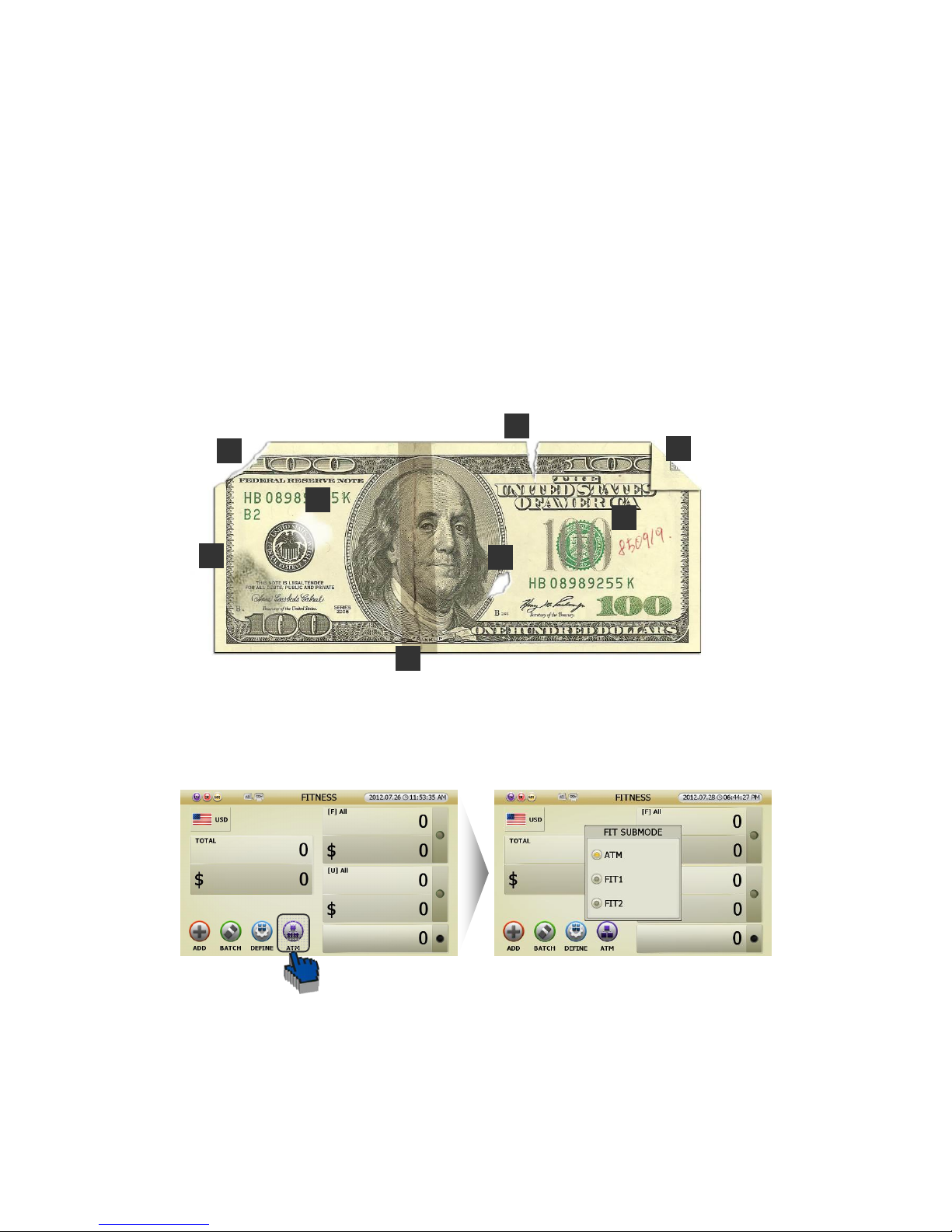
Fitness conditions
Soiling (Dirty): General Distribution of dirt across the entire banknote①
Tapes: Self② -explanatory
Tear: Self③ -explanatory
Missing corner: Self④ -explanatory
Holes: Self⑤ -explanatory
Corner folded (Dog⑥ -ears): Self-explanatory
Oil stain: Localized concentration of dirty⑦
Graffiti (Including stamp): Deliberate graphical alteration of the banknote⑧
FITNESS mode can be set up by 3 different Sub Modes. Touch [ATM] icon in FITNESS MODE (FIG 5-01).
Then, user can select the one of Fitness Sub-Mode in the initial screen (FIG 5-29).
You can set up one of 3 different modes with different value of 8 items of the Fitness standards.
You can set FITNESS MODE in Admin. MENU. (Referring to page 49)
(FIG 5-29)
①
②
③
④
⑤
⑥
⑦
⑧
(FIG 5-01)
(FIG 5-28)
Page 51
51
● Pocket Arrange designation
Can classify and designate previously set [Stacker 1] and [Stacker 2] by pressing [CHANGE] button in
FITNESS Mode. (Referring to page 22)
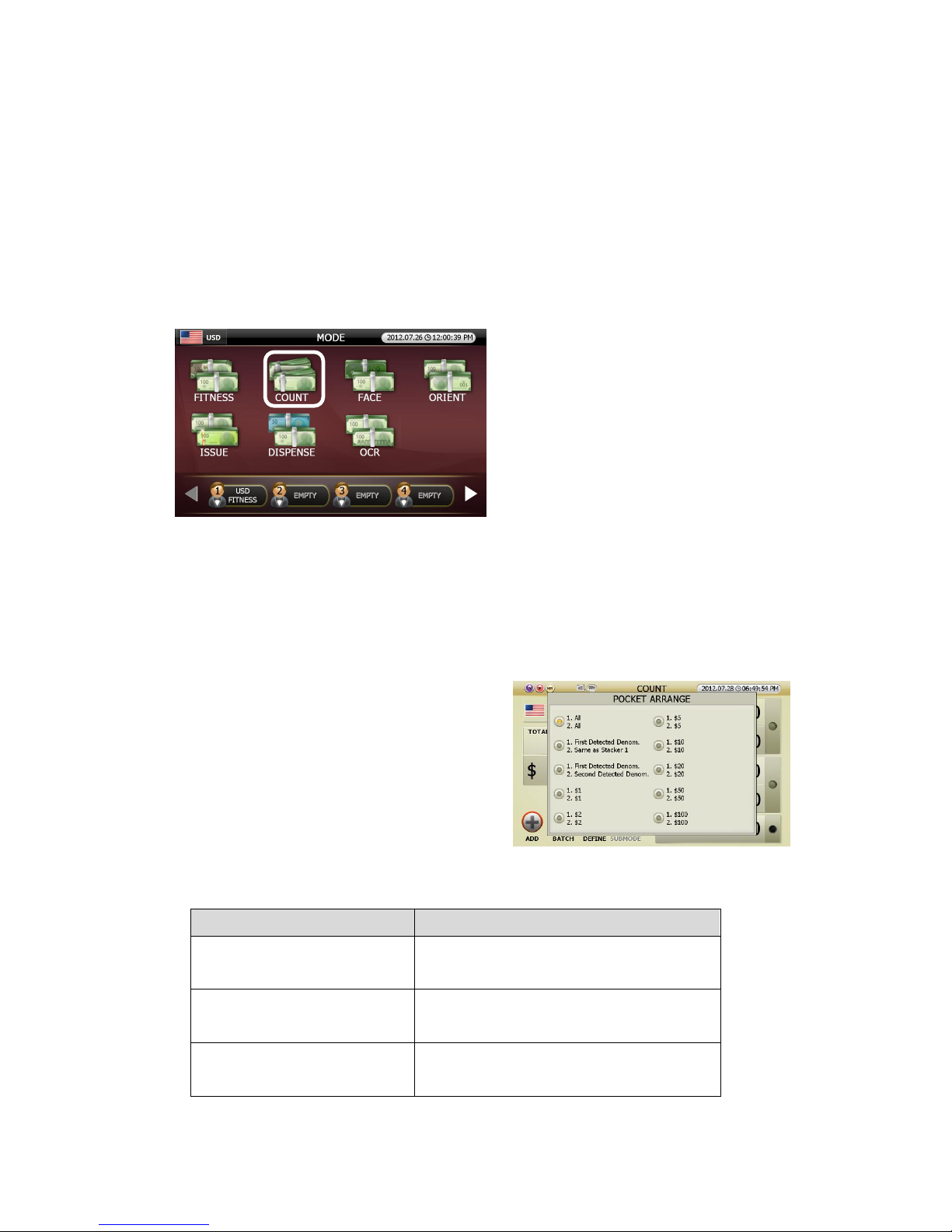
■ COUNT MODE
One function is called Mixed mode that can
detect and count the value of mixed
denominations, another function is called Single
mode that can detect and count the value of
designated denomination only.
In order to use single mode function, select single denomination in Pocket Arrange screen, and in order to
use mixed mode, select all denominations in Pocket Arrange screen. In addition, the pockets of SB-3000
can be set up separately by user’s classification.
● Pocket Arrange designation:
Can classify and designate previously set [Stacker 1] and
[Stacker 2] by pressing [CHANGE] button in COUNT
Mode.
Below is description of the designated pocket (Referring to page 22)
Pocket Arrange Display Earmarked banknote in Stacker 1, Stacker 2
1. All
2. All
Stacker 1: All denomination
Stacker 2: All denomination
1. First Detected Denom.
2. Same as Stacker 1
Stacker 1: The first detected denomination
Stacker 2: Same denomination as Stacker 1
1. First Detected Denom.
2. Second Detected Denom.
Stacker 1: The first detected denomination
Stacker 2: The second detected denomination.
(FIG 5-30)
Page 52
52
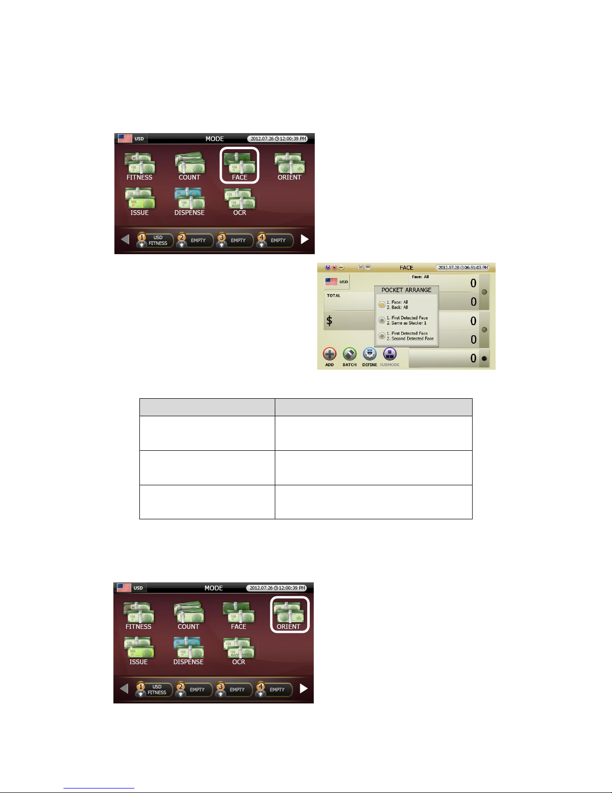
■ FACE Mode
FACE Mode discriminates and count the FACE
(HEAD) and BACK (TAIL) of notes.
● Pocket Arrange designation:
Can classify and designate previously set [Stacker 1]
and [Stacker 2] by pressing [CHANGE] button in
FACE Mode
Below is description of the designated pocket.
Pocket Arrange Display Earmarked Banknote in Stacker 1, Stacker 2
1. Face: All
2. Back: All
Stacker 1: All denomination with front face
Stacker 2: All denomination with rear
1. First Detected Face
2. Same as Stacker 1
Stacker 1: The first detected front face
Stacker 2: Same denomination of Stacker 1
1. First Detected Face
2. Second Detected Face
Stacker 1: The first detected front face
Stacker 2: The second detected front face
■ ORIENT Mode
ORIENT Mode classifies banknotes according to
the directions.
(FIG 5-31)
Page 53
53
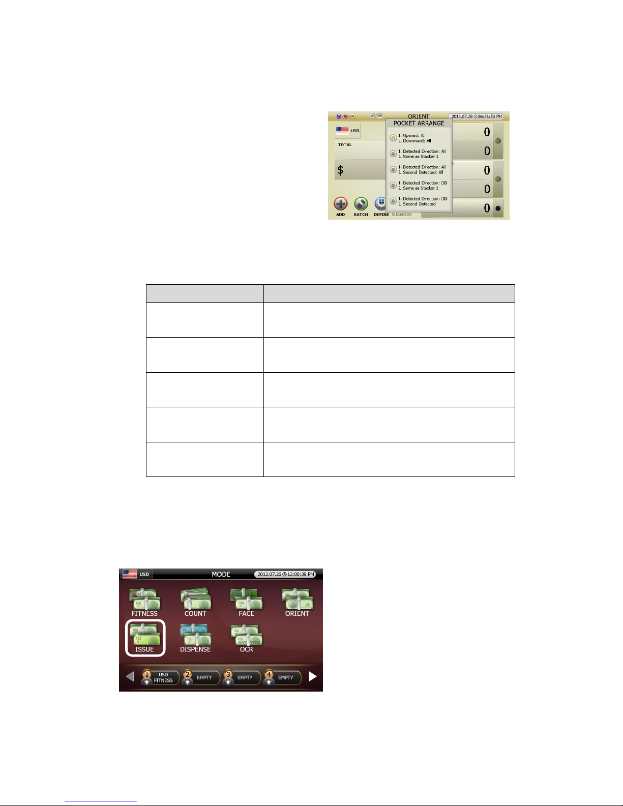
● Pocket Arrange Designation:
Can classify and designate previously set [Stacker 1]
and [Stacker 2] by pressing [CHANGE] Button in
ORIENT mode.
Below is description of the designated pocket.
Pocket Arrange Display Earmarked Banknote in Stacker 1, Stacker 2
1. Upward: All
2. Downward: All
Stacker 1: All denominations in upward
Stacker 2: All denominations in downward
1. Detected Direction: All
2. Same as Stacker 1.
Stacker 1: The first detected direction in all denominations
Stacker 2: Same as Stacker1
1. Detected Direction: All
2. Second Detected: All
Stacker 1: The first detected direction in all denominations
Stacker 2: The second detected direction in all denomination
1. Detected Direction: DD
2. Same as Stacker 1
Stacker 1: The first detected direction
Stacker 2: Same as Stacker1
1. Detected Direction: DD
2. Second Detected
Stacker 1: The first detected direction
Stacker 2: The second detected direction
■ ISSUE Mode
ISSUE Mode classifies and counts bank notes
by the old and new issue.
(FIG 5-32)
Page 54
54
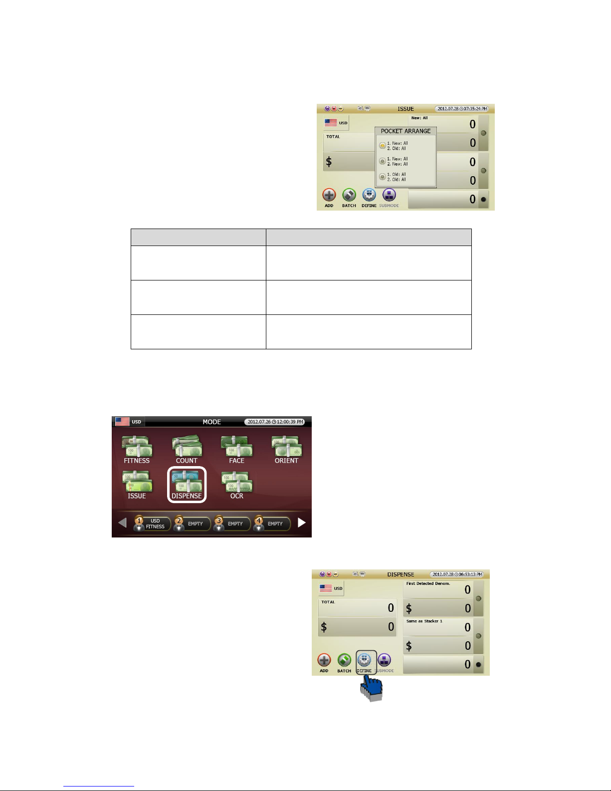
● Pocket Arrange Designation:
Can classify and designate previously set [Stacker 1]
and [Stacker 2] by pressing [CHANGE] button in
ISSUE mode.
Below is description of the designated pocket
Pocket Arrange Display
Earmarked banknote in Stacker 1, Stacker 2
1. New: All
2. Old: All
Stacker 1: new issue banknotes
Stacker 2: The old issue banknotes
1. New: All
2. New: All
Stacker 1: The new issue banknotes
Stacker 2: The new issue banknotes
1. Old: All
2. Old: All
Stacker 1: The old issue banknotes
Stacker 2: The old issue banknotes
■ DISPENSE Mode
DISPENSE Mode is a Muti- Batch function to
dispense by certain q’ty of each denomination.
For instance, place bundles of USD 100 value in
each denomination, USD 1, USD 5, USD 10,
USD 20 in the hopper, This mode can dispense
in 100 notes of USD 1, 20 notes of USD 5, 20
notes of USD 5 and 10 notes of USD 20
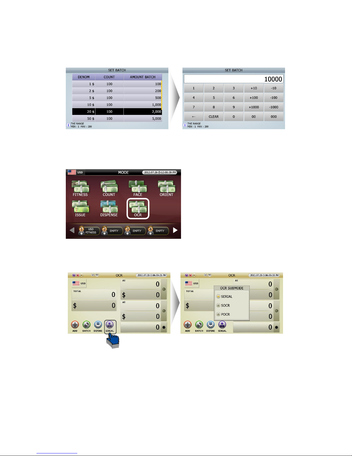
Follow below procedure to set up by each
denomination.
[1] Touch (BATCH) icon in DISPENSE mode
(FIG 5-34)
(FIG 5-33)
Page 55
55
[2] Set up by each denomination in [SET DEMON, BATCH] screen.
■ OCR Mode (Option)
SB-3000 can read and print characters of Serial
No. in banknotes.
OCR mode has four Sub Modes. Touch [SERIAL] icon in OCR Mode (FIG 5-37) and user can select
SERIAL or SOCR or POCR in OCR SUBMODE (FIG 5-38).
OCR Mode has four sub options as below.
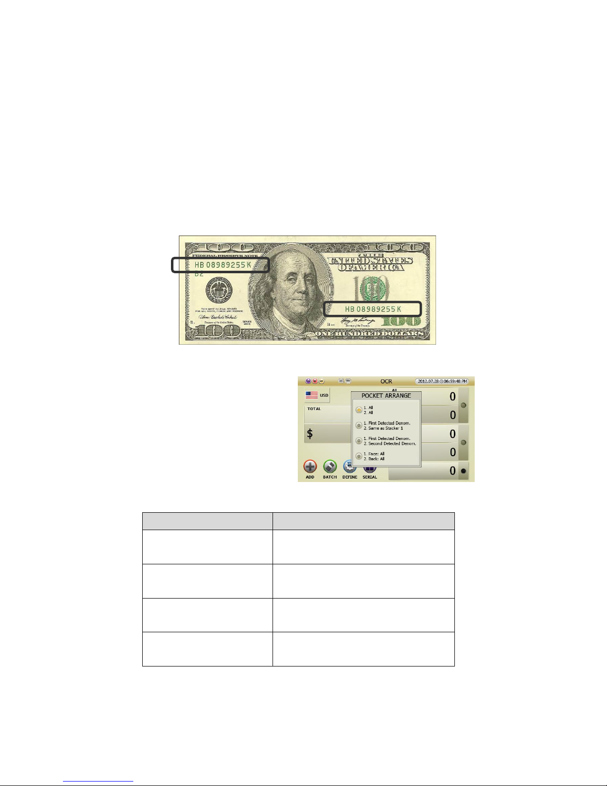
1 SERIAL Mode (Serial Number Printing Mode): In SRLP mode, SB-3000 reads serial No of banknote and
prints it as an image.
2 SOCR (SB series-Optical Character Reader Mode): In S-OCR mode, SB-3000 reads the serial no. of
banknotes and prints its images.
(FIG 5-35)
(FIG 5-36)
(FIG 5-37)
(FIG 5-38)
Page 56
56
3 POCR (PC-Optical Character Reader Mode): In P-OCR mode, SB-3000 reads serial numbers. of
banknotes and prints them as images and at the same time, the images are sent to the PC. By running the
application program on the computer, user can read the image and convert it into OCR data so that user
can store and manage it.
4 [OPTION] SNC Mode (Serial Number Comparison Mode): In SNC mode, SB-3000 can read the serial
number and can identify the both serial numbers in the banknote. In case the serial numbers are not
identical, the note will be sent to the reject pocket and indicated as “SNC ERROR”
● Pocket Arrange Designation:
Can classify and designate previously set
[Stacker 1] and [Stacker 2] by pressing
[CHANGE] button in OCR Mode.
Below is description of designated pocket.
Pocket Arrange Display
Earmarked banknote in Stacker 1, Stacker 2
1. All
2. All
Stacker 1: All denominations
Stacker 2: All denominations
1. First Detected Denom.
2. Same as Stacker 1
Stacker 1: The first detected denomination
Stacker 2: same denomination as Stacker 1
1. First Detected Denom.
2. Second Detected Denom.
Stacker 1: The first detected direction
Stacker 2: The second detected direction
1. FACE: All
2. BACK: All
Stacker 1: All denominations of front
Stacker 2: All denominations of rear
(FIG 5-39)
(FIG 5-40)
Page 57
57
5.2.3. User Define Mode
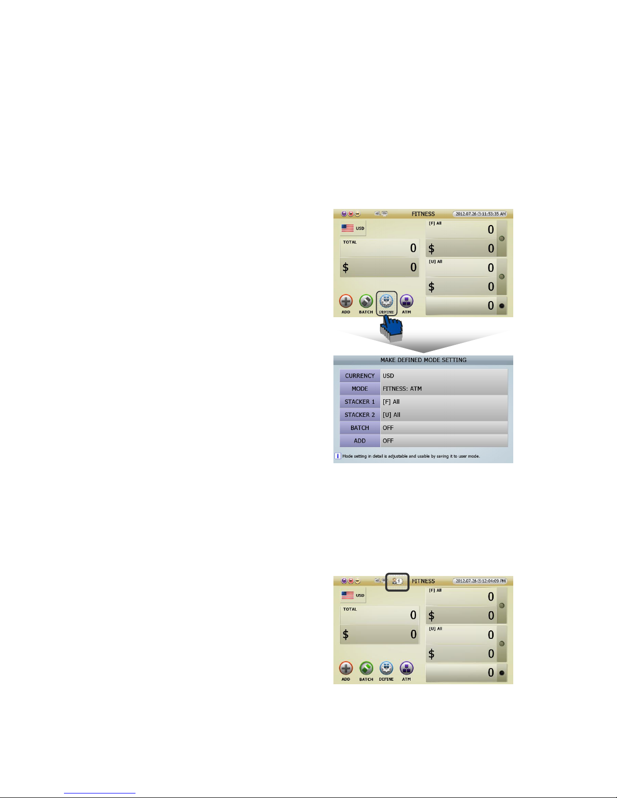
‘User Define Mode’ means that user can set up Max 8 modes for his/her usual or specific purpose. User
can set and save his/her own mode and can select easily just touching this icon.
● How to set User Define Mode
1 In order to set in initial screen
[1] Touch [DEFINE] icon in initial screen (FIG 5-01),
and can enter ‘MAKE DEFINED MODE SETTING (FIG
5-05).’
[2] Can set Currency, Working Mode, Stacker 1&2,
Batch On/Off and Add function On/Off like right
picture(FIG 5-05).
[3] If the setting is decided, press [START/STOP] button to save. Pree [C] to cancel the setting.
[4] Press [START/STOP] button, and can save the ‘User Define Mode’ number(No.1) and this will be
activated.
[5] The picture on the right is that screen indicator
shows ‘User Define Mode(No.1)’ is activating.
(FIG 5-01)
(FIG 5-05)
(FIG 5-06)
Page 58
58
2 In order to set in ‘User Define Mode’
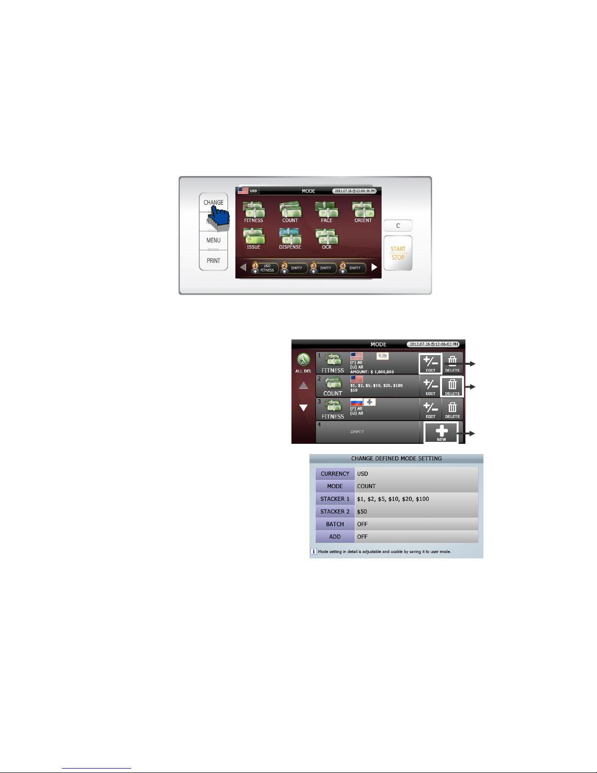
[1] Pressing [MODE] button in initial screen (FIG 5-01), the screen will be will changed into’MODE
selection.’(FIG 5-03).
[2] Pressing [CHANGE] button in ‘MODE selection’(FIG 5-03), the screen will be changed into ‘User
Define Mode’ (FIG 5-07).
[3] Can set details in this ‘Mode’.
① In order to set up new User Mode, touch
[New] icon and activate ‘MAKE DEFINED
MODE SETTING.’ stage(FIG 5-05)
② In order to edit previous User
Mode, touch [EDIT] icon and activate ‘CHANGE
DEFINED MODE SETTING.’(FIG 5-
08) Change and save the details.
③ In order to delete the previous User Mode,
touch [DELETE] icon.
(FIG 5-07)
(FIG 5-08)
①
②
③
Page 59
59
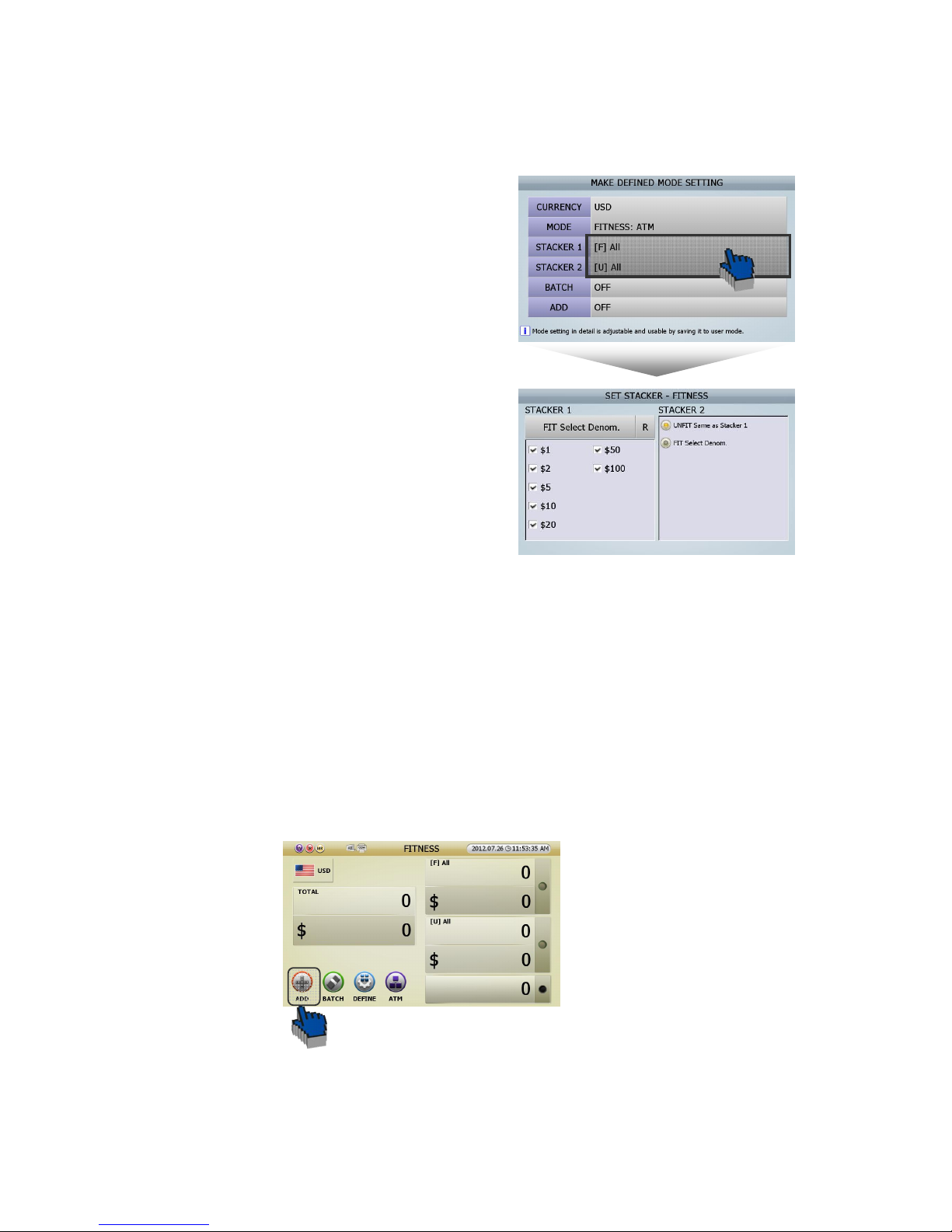
● Can change the stacker pockets like below in User Define Mode.
[1] In order to activate ‘MAKE DEFINED MODE
SETTING(FIG 5-05),’ User can touch [DEFINE] icon in
initial screen (FIG 5-01).
[2] Press [Stacker 1]/[Stacker 2], then user can see ‘SET
STACKER-FITNESS(FIG5-09)’ like the picture on the
right.
[3] Can select the notes in ‘FIT Select Denom.’ list in
‘Set Stacker-Fitness(FIG 5-09)’ stage.
[4] Save in ‘User Define Mode’ and user can start to work.
5.2.4. Functions
■ ADD Function
In general situation, counting result initialize when pocket empty, but if ADD button was activated, counting
result is displayed by automatically added from the previous counting result even if pocket is empty.
Caution) ACCEPT function is not available when ADD is set.
● ADD is activated by touching ADD button on the screen of each mode.
(FIG 5-09)
(FIG 5-05
)
(FIG 5-01)
Page 60
60
■ BATCH Function
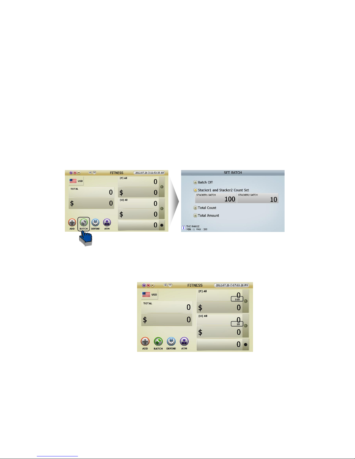
Batch is used when user want to count specific number of banknotes. For example, Batch is used when
user want to count 50pcs of banknotes while Stacker pocket capacity is set to 100pcs.
When BATCH Function is on, operation is stopped after counting the number user set in advance even if
banknotes still remain on Hopper. Batch size cannot exceed Stacker pocket’s maximum size.
● How to set
[1] Set Batch screen is generated by touching Batch button on the display of each mode.
[2] Can set on Set Batch screen (FIG -41).
Batch off: Do not use Batch function. ①
Stacker 1 and Stacker 2 Count Set: Set Batch numbe② r for Stacker 1 and Stacker 2 respectively.
(FIG 5-41)
(FIG 5-01)
(FIG 5-42)
Page 61
61
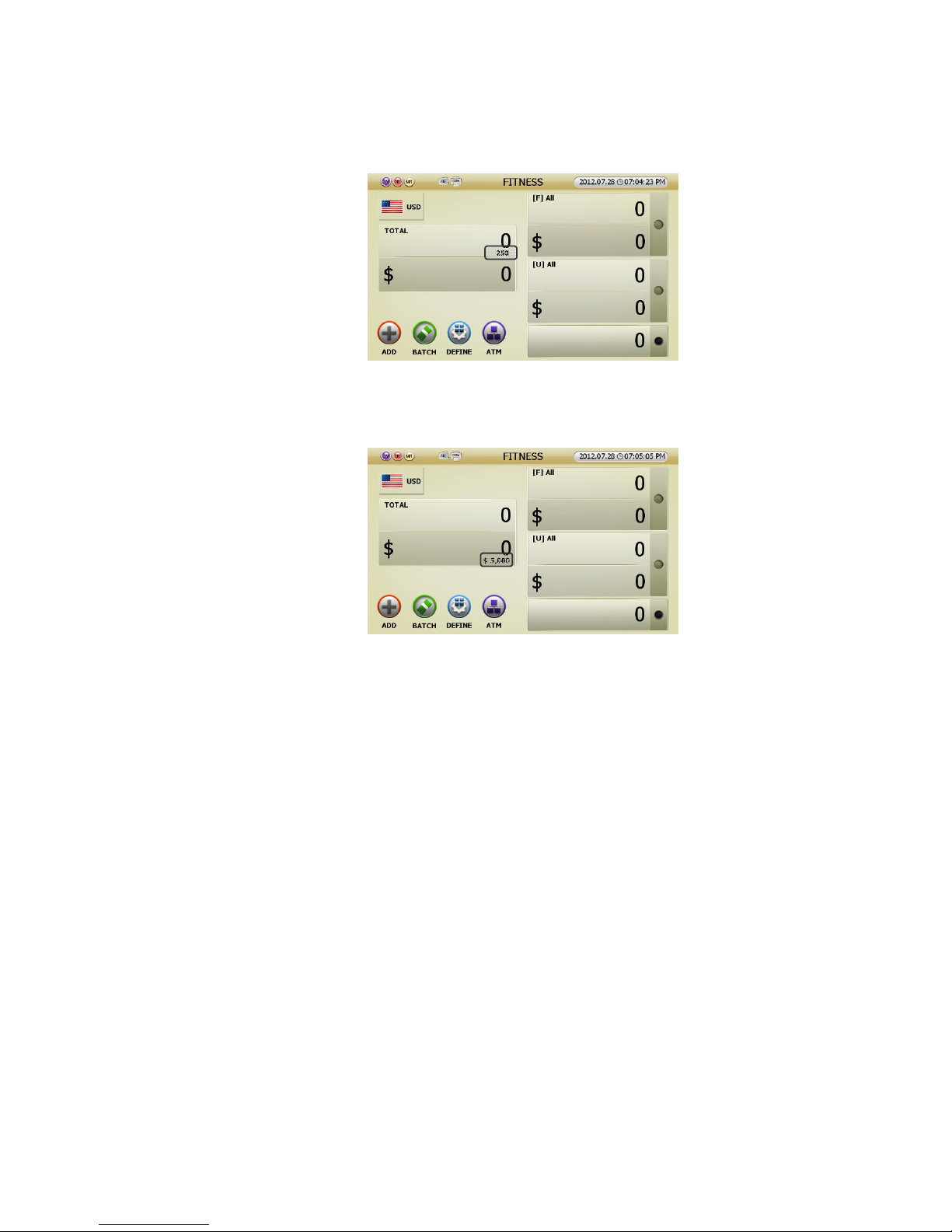
Total Count: Set Batch number for Stacker 1 and Stacker 2 in total. ③
④ Total Amount: Set Batch amount for Stacker 1 and Stacker 2 in total.
(The same as Dispense Mode from other models)
[3] Change to the initial screen after Batch setting.
(FIG 5-44)
(FIG 5-43)
Page 62
62
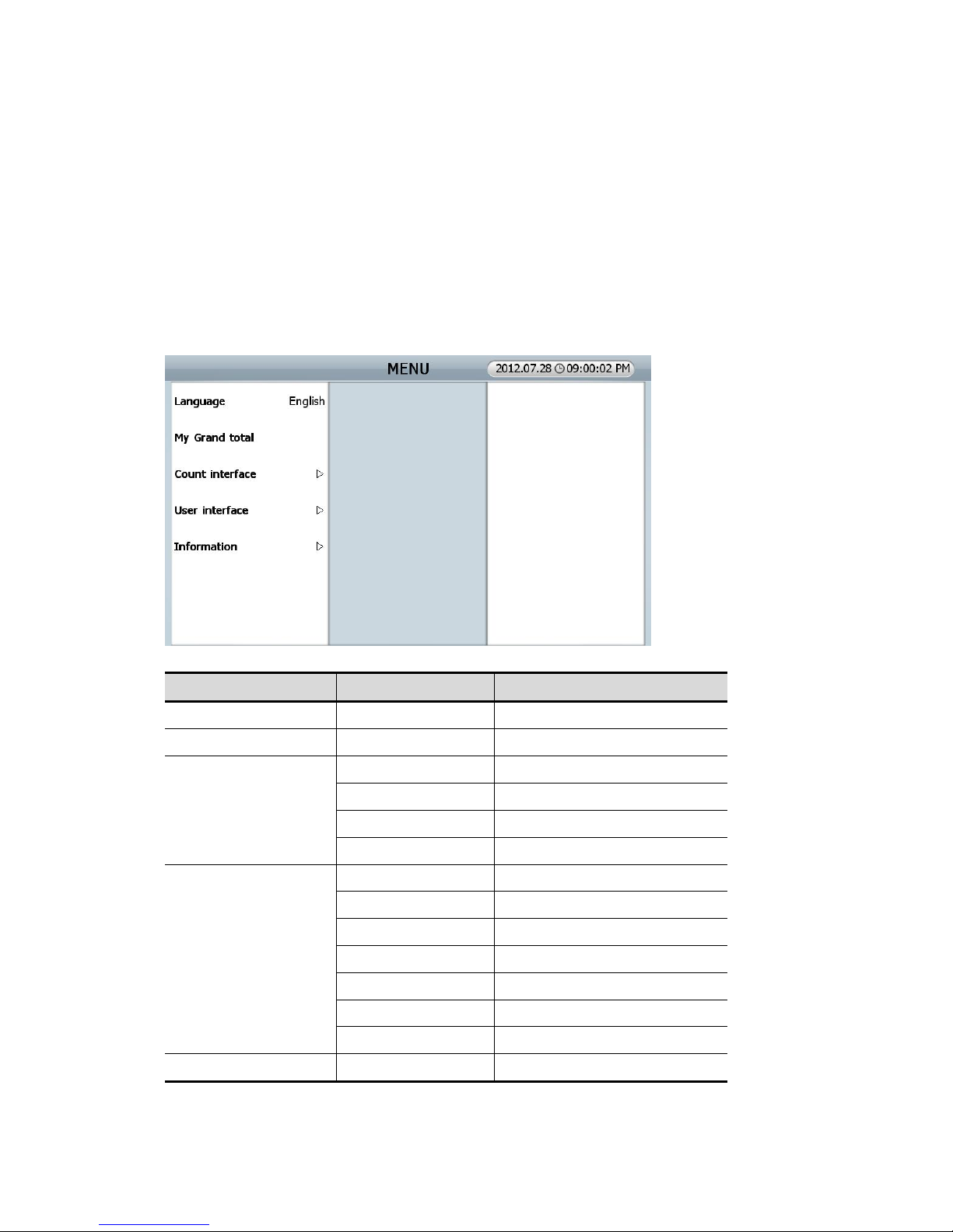
6.0.0. USER MENU (for USER)
SB3000 has 2 kinds of Menu. One is a “User Menu” for user, and the other is “ADMIN Menu” for
administrator.
Can alter each function and parameter. Push [MENU] key, user can move to “USER MENU” and its details
by Touching the items.
MENU Sub Menu Description
Language Set a menu language
MY grand total Checking of each User’s GT
Count Interface
Start counting Manual/automatic counting start
Pocket capacity Set “pockets’ capacity”
Accept result Set “Accept result”
Print result Set “Printing result”
User Interface
Touch calibration Touch calibration for screen
Set date/time Set up date/time
Selection way Set up selection method
Sorting order Set up sorting order
LCD brightness Set up LCD brightness.
Beep Set up warning beep
Power saving Set up power saving
Information About SB3000 Set up SB-3000 inside.
(FIG 6-01)
Page 63
63
A/S call number Check service call number.
In order to move on lower menu section, it’s available with “Touch Screen” or [CHANGE] key,
[START/STOP] key, and [C] key.
Language: Set up the language for Menu.
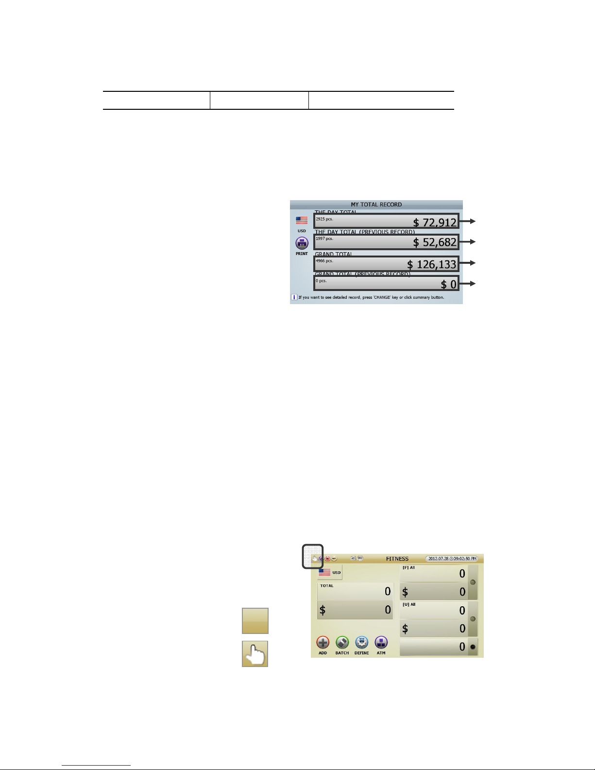
My grand total: Instructing “The Day Total & Grand Total” of current user.
[1] MY TOTAL RECORD (FIG 6-02)
[2] At “MY TOTAL RECORD”, pressing [CHAGNE] Key consecutively, or touching each section of “total
result , user can change 4 types of display.
Touching “THE DAY TOTAL” section (①
ⓐ
), then moving onto
“MY TOTAL RECORD _ THE DAY TOTAL”
Touching “THE DAY TOTAL (PREVIOUS RECORD)” section (②
ⓑ
), then moving onto
“MY TOTAL RECORD _ THE DAY TOTAL (PREVIOUS RECORD)”
Touching “GRAND TOTAL” section (③
ⓒ
), then moving onto
“MY TOTAL RECORD _ GRAND TOTAL”
Touching “ GRAND TOTAL (PREVIOUS RECORD)” section(④
ⓓ
), then moving onto
“MY TOTAL RECORD _ GRAND TOTAL (PREVIOUS RECORD)”
[3] Can print out with pressing [PRINT]key or touching [PRINT] icon at each screen
(Refering to page 25)
Count Interface
1. How to start counting: User can set up the start
manual or automatic.
Default is Automatic Counting Start
1) Automatic Counting Start:
(none)
2) Manual Counting Start:
(FIG 6-02)
(FIG 6-03)
ⓐ
ⓑ
ⓒ
ⓓ
Page 64
64
2 Pocket capacity: How to set up stacker capacity of each pocket.
1) Stacker Pocket #1: Can be selected one of 100/150/200
2) Stacker Pocket #2: Can be selected one of 100/150/200
3) Reject pocket: Can be selected one of 50/70/100
3 Accept result: How to set up the “Accept” in order to sum counting result to “GT”.
1) Auto-accept: User can set whether automatic “Accept” or manual “Accept” after counting.
2) After-accept: User can set manual “Accept” after checking the counting result.
① Only add Count-result to Grand-total
② Add to Grand-total and print
③ Add to Grand-total and print twice
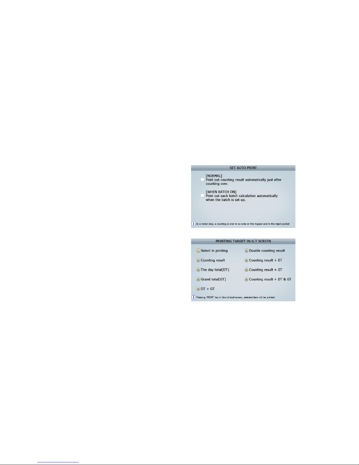
4 Print result : User can set up the printing out method after counting.
1) Auto-print: user can set automatic/manual
print out.
① generally, print out the counting result
automatically just after counting over.
② n “Batch” function on, print out calculation
automatically when the batch is set up.
2) Print mode: can set up a subject of printing
out in Grand-total screen
User Interface
1. Touch screen calibration
2. Setting of date/ time
3. Selection method of items: can set up the Selection method of items.
① Select an item at pop up lists.
② Select next level of item without pop up.
4. Arrangement order : can set up the arranged values on screen by descending or ascending order
5. Screen brightness : Adjust LCD brightness
6. Sound : set up warning beep.
7 Power saving mode : Setting up power saving mode in idle time
(FIG 6-04)
(FIG 6-05)
Page 65
65
Information
1 About SB-3000 : Machine information
2 A/S call number: After Service call number
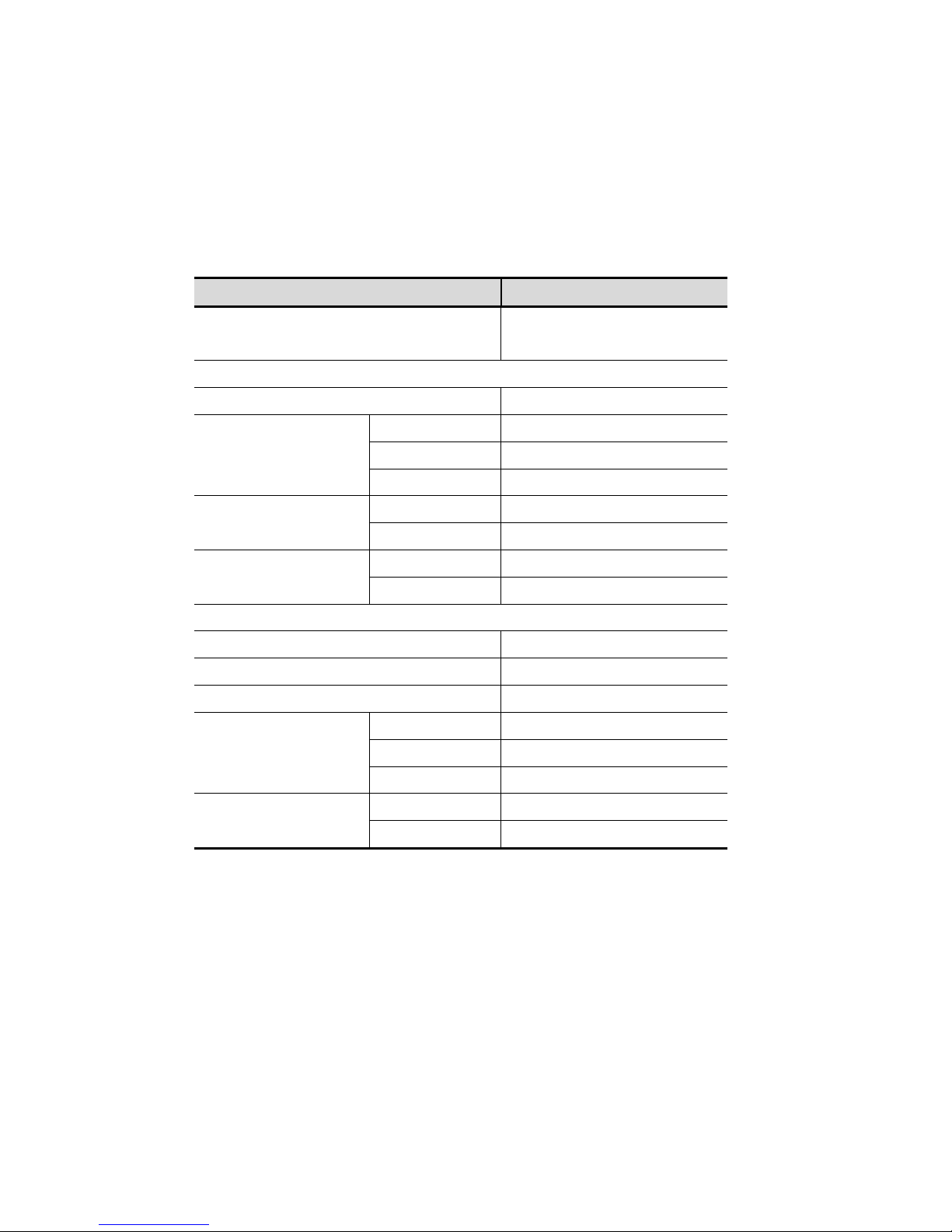
The Factory default settings are like below.
Function Default Value
Speed
1000NPM
(Fitness Mode: Approx. 700)
[Count interface]
Starting counting Auto
Pocket capacity
Stacker Pocket #1 100
Stacker Pocket #2 100
Reject Pocket 50
Accept result
Auto-accept off
After accept Only add count-result to grand-total
Print result
Auto-print off
Print in GT Select when printing
[User interface]
Selection way In list (On a pop-up menu.)
Sorting order Ascendant
LCD brightness 30
Beep
Beep volume 7
Warning on/off On
Button on/off On
Power saving
Waiting time 10
Saving type Make the back-light of LCD darker
Page 66
66
7.0.0. ADMIN MENU (Administrator Menu)
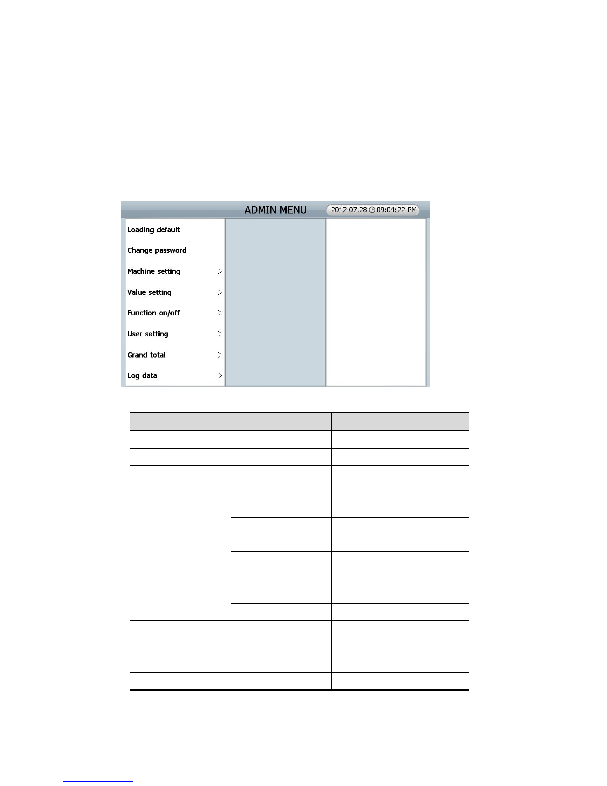
Can alter each function and parameter at this menu. Press [Mode] button and put [12345] in
Password screen, and will be moved to [ADMIN MENU]. Touch the screen items, and can move to
menus.
MENU SUB MENU Description
Loading default
Change password
Machine setting
Station ID Set the ID number of machine
Ethernet Set up LAN
Printer Set up print
Custom display Set up customer display
Value setting
CF level Set up CF notes’ level
Fitness Set up Fitness function and
Saved fitness level date in/out
Function on/off
CF items CF item on/off
Tape in count mode Tape sensor on/off
User setting
Concurrent User Set up concurrent user
Setting place Set up displaying location of
counting user interface
Grand Total Grand total type Set up GT type
(FIG 7-01)
Page 67
67
Clear Delete GT
Initialize all Initializing GT
Summary Check the summary of GT
Each user Check GT for each user
Log data Export log data
Loading default (Get back to initial condition)
All of parameters get back to initial setting of factory
Change passwords
Administrator’s password can be changed at this menu.
In order to manage the result data and parameter in Admin Menu, strongly recommended to be
accessed only authorized administrator.
Thus it is recommended changing the initial password [*****] to specified password of its
administrator.
Machine setting
1 Station ID
The ID number of the machines will be printed out after setting up the ID number
2 Ethernet: Can set up Dynamic / Static IP address in LAN setting.
3 Print: Set up Print.
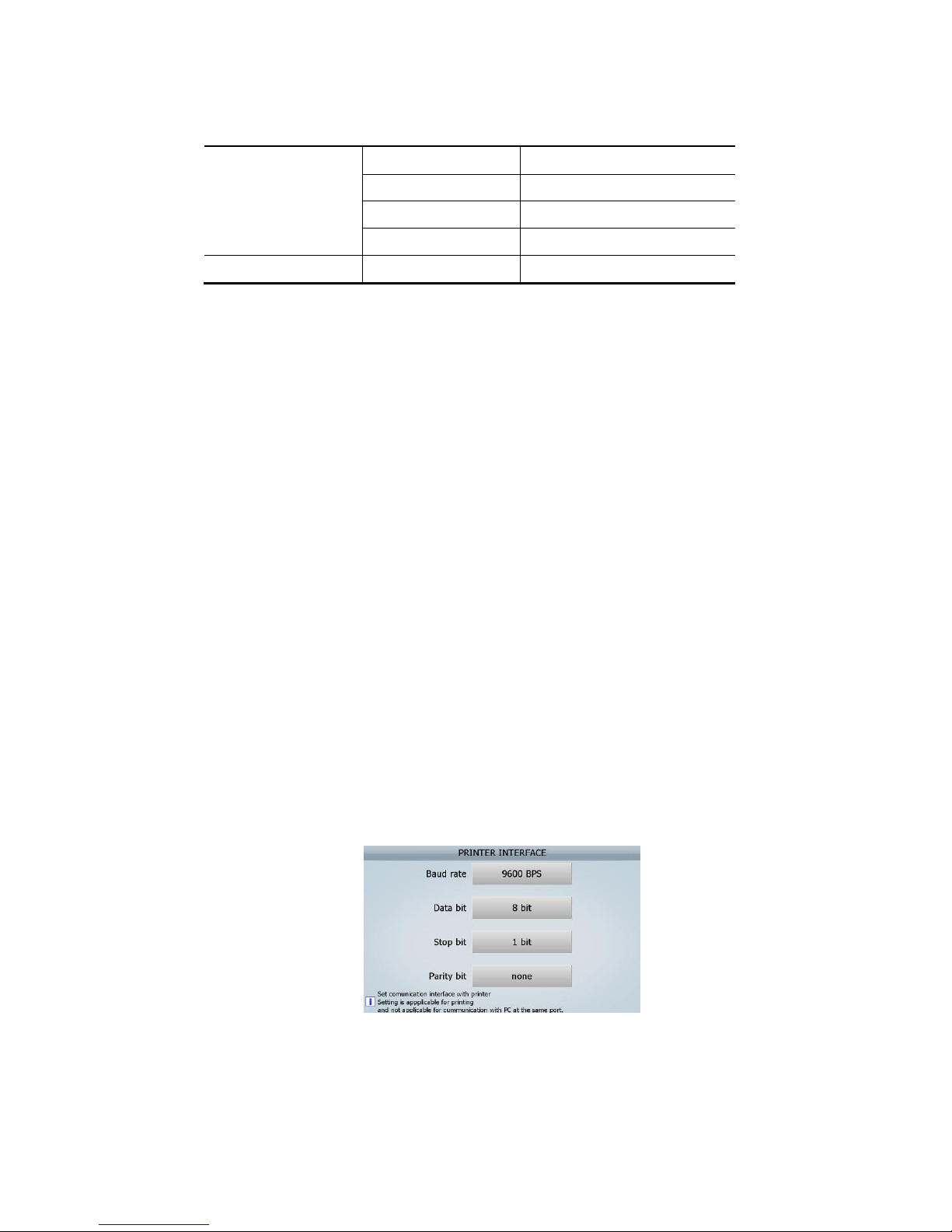
1) Interface
Administrator has to select a printer type before connecting the printer.
Needs to be discussed with the dealer about available printer
If, the printer type is Serial, the setting of printer in SB-3000 is like below.
2) Cutting code
Can set up the Cutting code with reference the manual and it can apply up to 6 byte.
3) Each user
(FIG 7-02)
Page 68
68
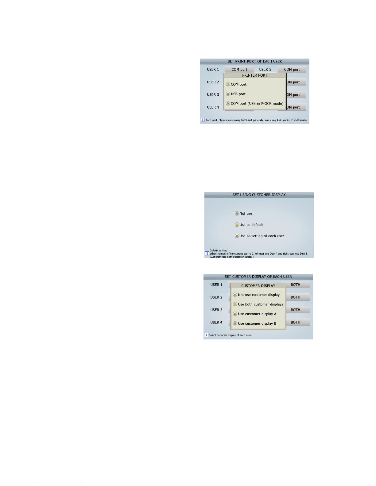
Set up printer ports for each user.
About COM port (USB in P-OCR Mode) means
that generally COM port is used and USB ports
are used at the same time in P-OCR mode.
4 Customer display
Set up the Customer Displays to be connected to Display A/ B Ports.
1) Display A: Set up a Customer Display for Display A.
2) Display B: Set up a Customer Display for Display B.
3) Display to use: set up a using Customer Display.
Caution) In case of set up concurrent user,
Display A is for left user, and Display B is for
right user. This is “Default setting,” but user can
set up the display for each user.
4) Each User
Set up the Customer display for each user.
Value setting
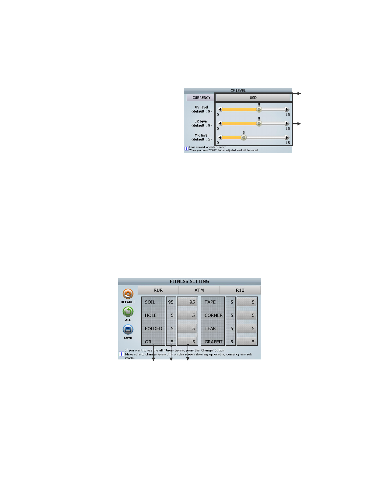
1. CF level
In this menu, user can set the levels such as UV (Ultra-Violet) Sensor, MR (Magnetic Reader)
Sensor and IR (Infrared) Sensor required detecting each currency. The setting method is as follows.
(FIG7-04)
(FIG 7-05)
(FIG 7-03)
Page 69
69
[How to set]
[1] Select Currency. (ⓐ)
[2] Move each circle and set the levels (ⓑ)
Move the circle of the first bar and ①
set UV level.
Move the circl② e of the second bar
and set IR level.
Move the circle of the third bar and ③
set MR level.
(It is possible to set each level in detail
by using “
” key◀▶
)
[3] Press [START/STOP] Key to save the level.
The lower number is less sensitive. If the machine detects CF note as real notes, increase level by
one to set the level. If the machine detect real note as CF note, decrease level by one to set the
level.
If the level is ‘0’ (Zero), the sensor is deactivated.
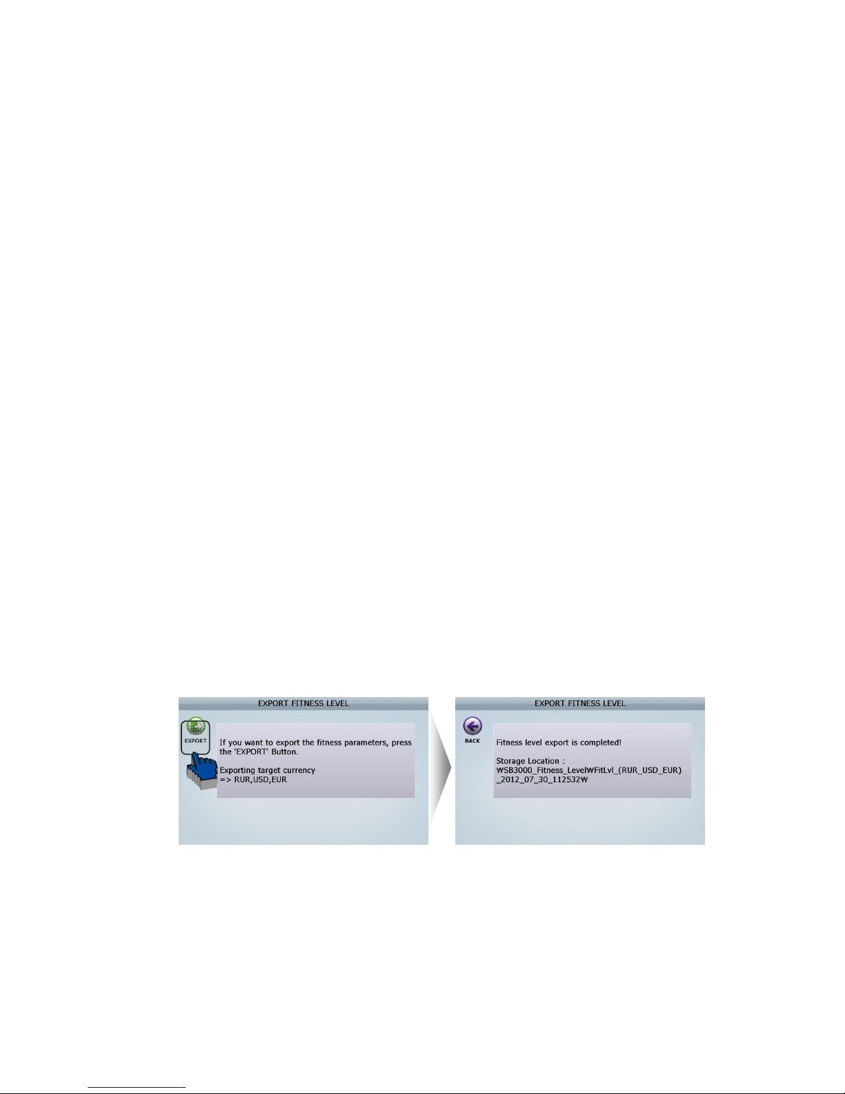
2 Fitness setting
[1] Fitness parameter
In this menu, user can set fitness sorting level for each currency and each denomination.
① [DEFAULT]: Set Fitness value to the Default
-. [YES]: Apply to all Fitness Sub-mode
-. [NO]: Apply only to current Fitness Sub-mode
-. [CANCEL]: Do not apply
(FIG 7-06)
ⓐ
ⓑ
(FIG 7-07
)
④ ⑤ ⑥
⑧ ⑨⑦
②
①
③
Page 70
70
② [ALL]: Decide if the data below is also applied or not to another denomination.
-. Fitness Levels & On/Off set
-. Fitness Levels
-. Fitness On/Off set
③ [SAVE]: Save current setting (Currency, Fitness Sub-mode, Denomination)
[CURRENCY]: The current currency’s displayed and if this is touched, another currency is set.④
[Fitness Sub⑤ -Mode]: The currency Fitness Sub-Mode is displayed and if this is touched,
another Fitness Sub-Mode is set.
[Denomination]: The currency denomination is displayed and if this is touched another ⑥
denomination is set.
[Fitness Sorting]: Items for fitness are displayed⑦ .
[Default]: The default of each item is displayed. ⑧
[Current value]: The current value for each item is displayed/⑨
[2] Import fitness level
[3] Export fitness level
Can put fitness level gotten from one machine into another machine by using Import fitness level
menu and Export fitness level menu.
Please refer to the below to know how to do this.
Follow the below steps
Insert USB Memory Stick to USB port in SB① -3000
Select ‘Export fitness level’ in this menu ②
(ADIMN MENU _ Value setting/ Fitness/ Export fitness level)
Touch on [EXPORT] Icon. Then LCD will be displayed as follows ③
The file is created in USB memory stick. ④
(File folder name: SB3000_Fitness_Level)
Insert USB Memory Stick, which has ‘SB3000_Fitness_Level’ folder, to⑤ another SB-3000
that supervisor want to input previously fitness level to.
Select ‘Import fitness level’ in this menu.⑥
(FIG 7-08)
(FIG 7-09)
Page 71
71
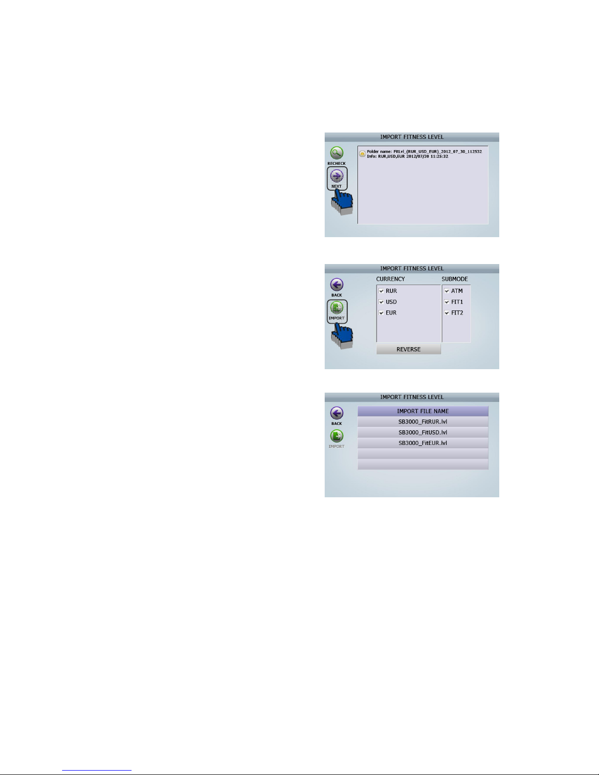
(ADIMN MENU _ Value setting/ Fitness/ Import fitness level)
LCD of another SB⑦ -3000 will be displayed as follows
-1. After checking the file which you want
to apply to another SB-3000. And then
touch [NEXT] Icon
-2. Select the currencies and fitness Sub-
Mode which supervisors want to apply
to another SB-3000. And touch
[IMPORT] Icon
-3. Finish
Finishes⑧
(FIG 7-11)
(FIG 7-12)
(FIG 7-10)
Page 72
72
Function on/off
1 CF Items
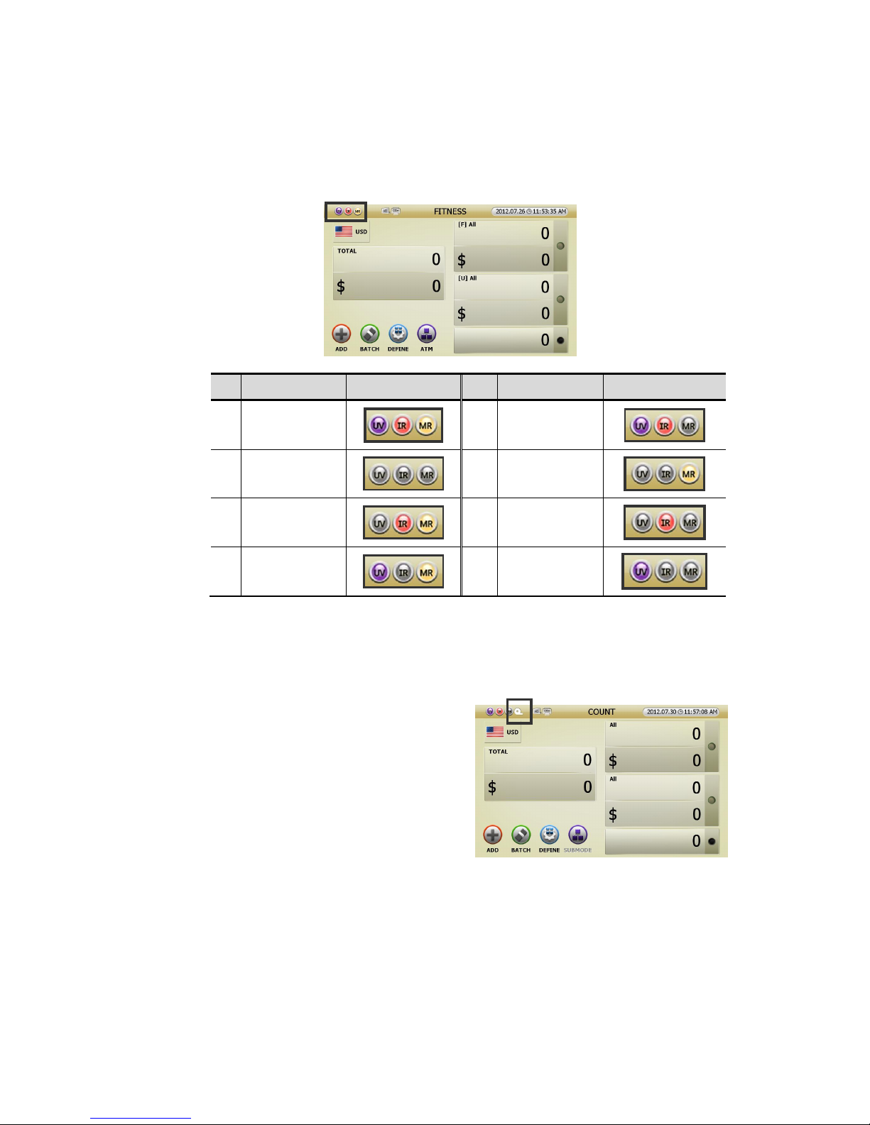
Administrator can set CF On/Off and can set sensors(UV, MR, IR) individually.
No Sensors status
Indicator No Sensors status
Indicator
1
CF on
(UV, IR, MR on)
5
MR off
UV on, IR on
2
CF off
(UV, IR, MR off)
6
UV off, IR off
MR on
3
UV off
IR on, MR on
7
UV off, MR off
IR on
4
IR off
UV on, MR on
8
IR off, MR off
UV on
2 Tape in count mode
Can set Tape Sensor ON/Off here, except for Fitness Mode.
In case of Fitness Mode, should set Tape sensor in
Fitness setting.
Tape function On, Tape indicator will be shown
like right picture (FIG 6-18).
User setting
1 Concurrent User
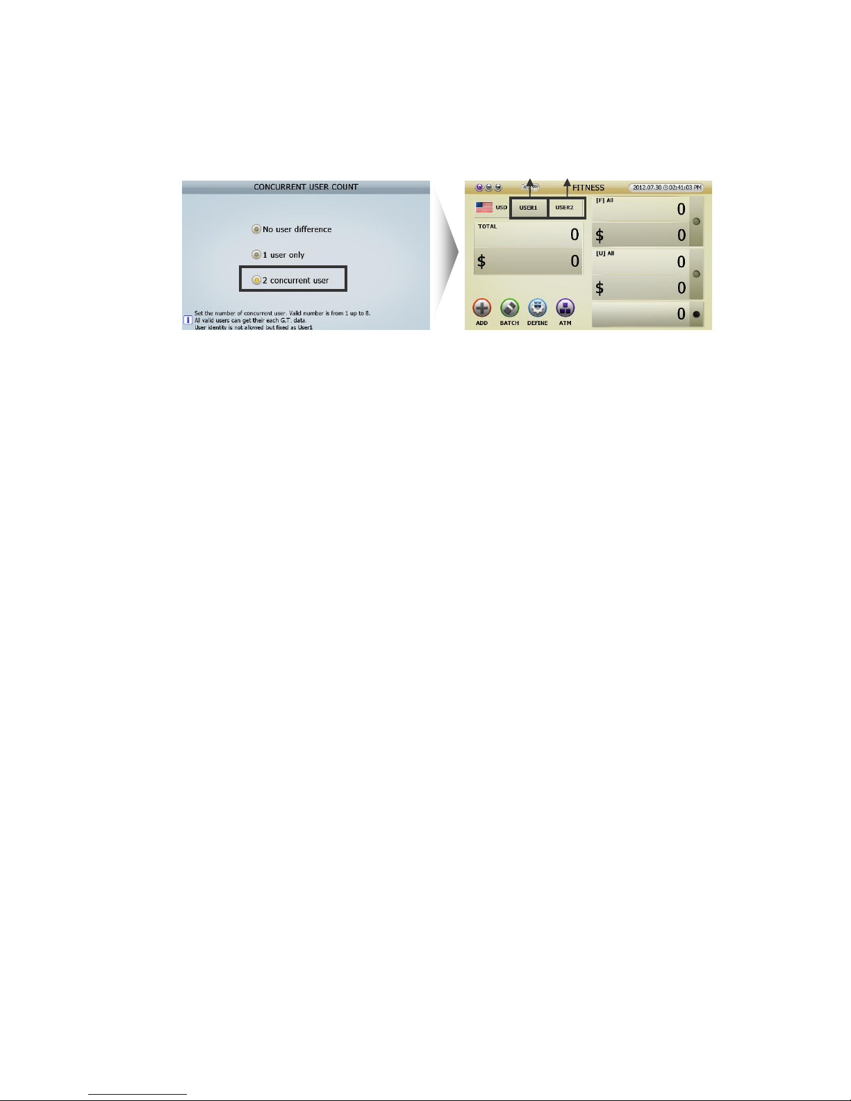
2 users can user SB-3000 at the same time. This is how to set Concurrent User. Without selecting
Concurrent User, ‘USER 1’ will be set.
(FIG 7-13)
Page 73
73
Setting 2 Concurrent User, the initial screen will be shown like below right.
[
1
]
[1] USER 1 and USER 2(ⓐⓑ) can operate SB-3000 at the same time in other modes.
User can slect one of Concurrent User and can set Count modes and functions as one user does.
[2] One of Concurrent User(ⓐⓑ) can use the allocated Print Port. (Referring to page 47) and
Customer Display. (Referring page 48) If Conccurent User was set, the allocated Print Port and
Customer Display will be shown in upper indicator.
[3] While the Concurrent User was set, if user touch the Concurrent User windows(ⓐ or ⓑ), USER
SETTING will be activated and user can change the Concurrent User setting.
2 Setting place
This is how to set CUTOMER DISPLAY and PRINT PORT.
① User can set only in MENU.
② User can set in MENU or Count Result display.
Grand Total
1 Grand Total type: Can set Grand total restart.
Can delete count record in ADMIN MENU.①
Count Record will restart every week (User should select the day, e.g. Monday.). ②
Count Record will restart every month (User should select the date, e.g. 15③
th
.).
Count Record will restart every year on ④ January 1st.
If the count record restarts, the counted record will remain as ‘PREVIOUS RECORD.’
2 Clear: Can restart THE DAY TOTAL and GRAND TOTAL.
3 Initialize all: Can delete the record and make THE DAY TOTAL and GRAND TOTAL zero.
4 Summary:
(FIG 7-15)
ⓐ ⓑ
(FIG 7-14)
Page 74
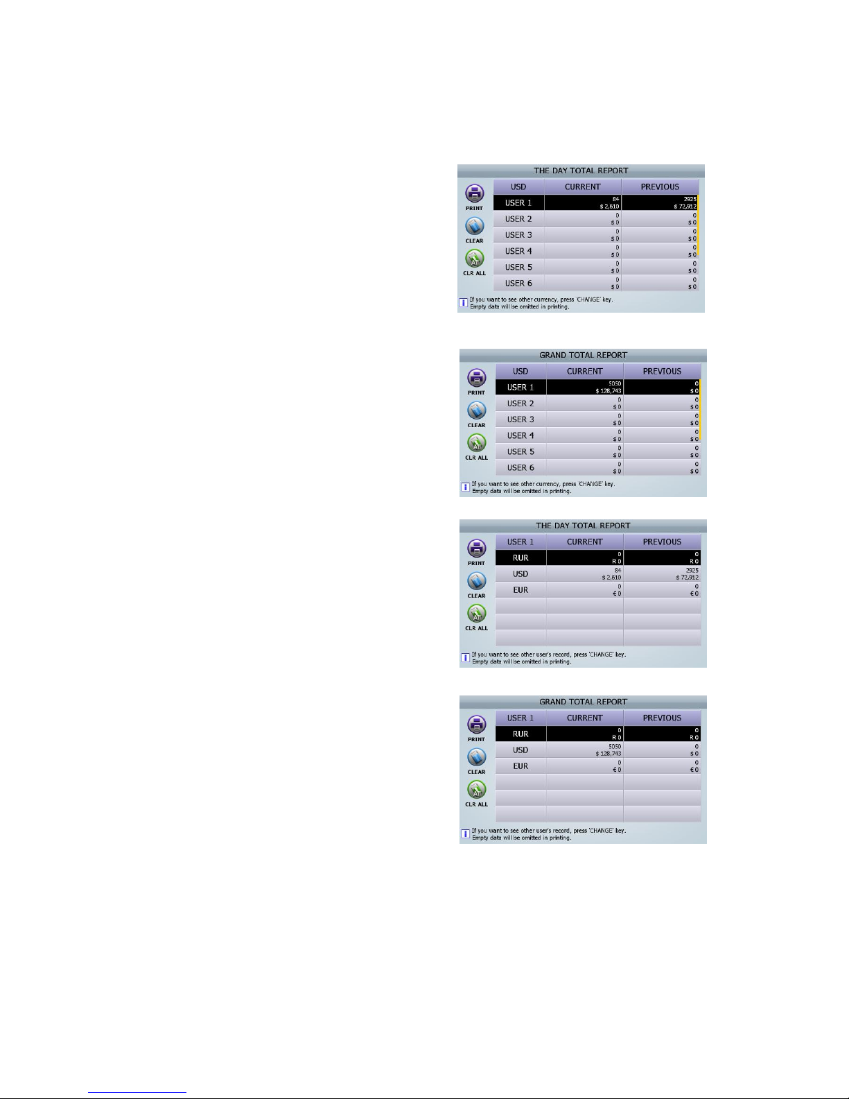
74
Can check, delete and print the summary of THE DAY TOTAL and GRAND TOTAL.
[1] THE DAY TOTAL by currency:
Pressing [CHANGE] button, the currency will be
changed.
[2] GRAND TOTAL by currency:
Pressing [CHANGE] button, the currency will be
changed.
[3] THE DAY TOTAL by user:
Pressing [CHANGE] button, the users will be
changed.
[4] GRAND TOTAL by user:
Pressing [CHANGE] button, the users will be
changed.
5 Each user:
Each user can read, delete and print the present & previous THE DAY TOTAL and GRAND TOTAL.
(FIG 7-16)
(FIG 7-17)
(FIG 7-18)
(FIG 7-19)
Page 75
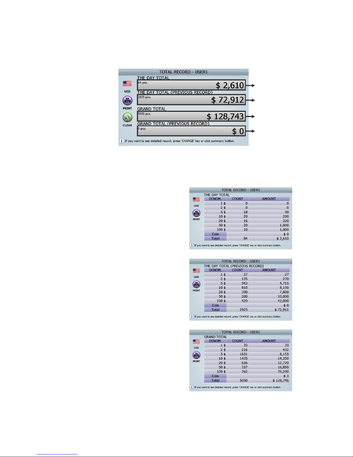
75
[1] the screen of TOTAL RECORD-USER1 DISPLAY is like below (FIG 6-25)
[2] If [CHANGE] button is pushed consecutively or if the section of the above screen is touched, the
above screen is changed to 4 DETAIL screens.
If the section (① ⓐ) of the above screen is
touched, the screen of ‘The Day Total’
screen as right will be changed.
If the section (② ⓑ) of the above screen is
touched, the screen of ‘The Day Total
(Previous record)’ as right will be changed.
If the section (③ ⓒ) of the above screen is
touched, the screen of ‘Grand total’ as right
will be changed.
ⓐ
ⓑ
ⓒ
ⓑ
(FIG 7-20)
(FIG 7-21)
(FIG 7-22)
(FIG 7-23)
Page 76
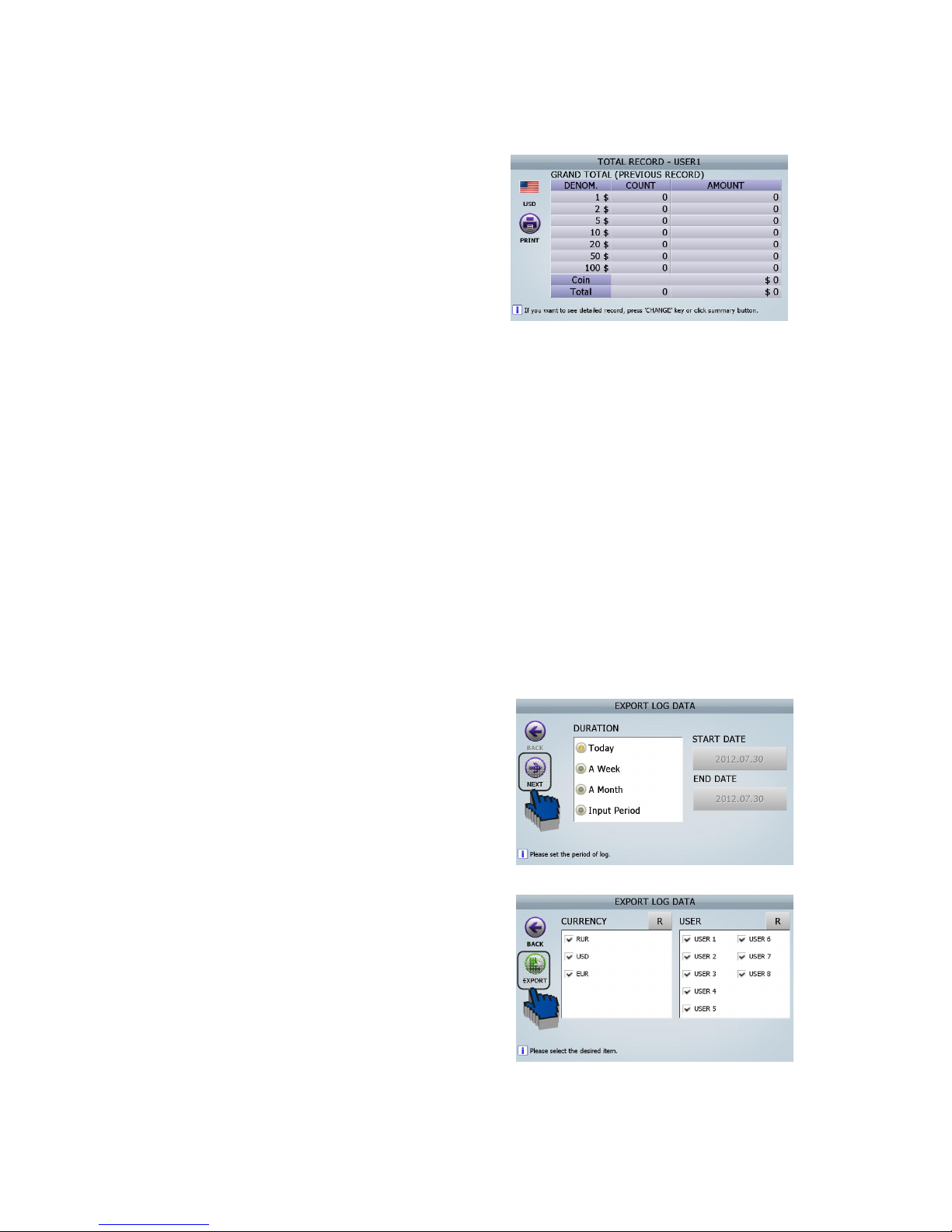
76
If the section (④ ⓓ) of the above screen is
touched, the screen of ‘Grand total
(Previous record)’ will be changed.
[3] In every screen, can print out the result by using [PRINT] button and [PRINT] ICON.
[4] In every screen, can delete the result by using [CLEAR].
Log data
This mode supplies all Log DATA ( Count Detail in Currency / Count Detail in User / Error Number /
Upgrade Number / Calibration Number / ETC ) and provide exporting function to EXCEL file.
The procedure of Log Data Exporting is here below,
① Insert USB Memory Stick into the USB Port of SB-3000.
② Select ‘Export log data’ in this menu
(ADIMN MENU _ Log Data/ Export log Data)
Select the Range of the Period. ③
Touch on [Next] ICON. ④
Select Currency and USER and Touch [Expo⑤ rt]
ICON.
(FIG 7-24)
(FIG 7-25)
(FIG 7-26)
Page 77

77
In USB Memory Stick, Log DATA file will be ⑥
created as right screen.
(FIG 7-27)
Page 78
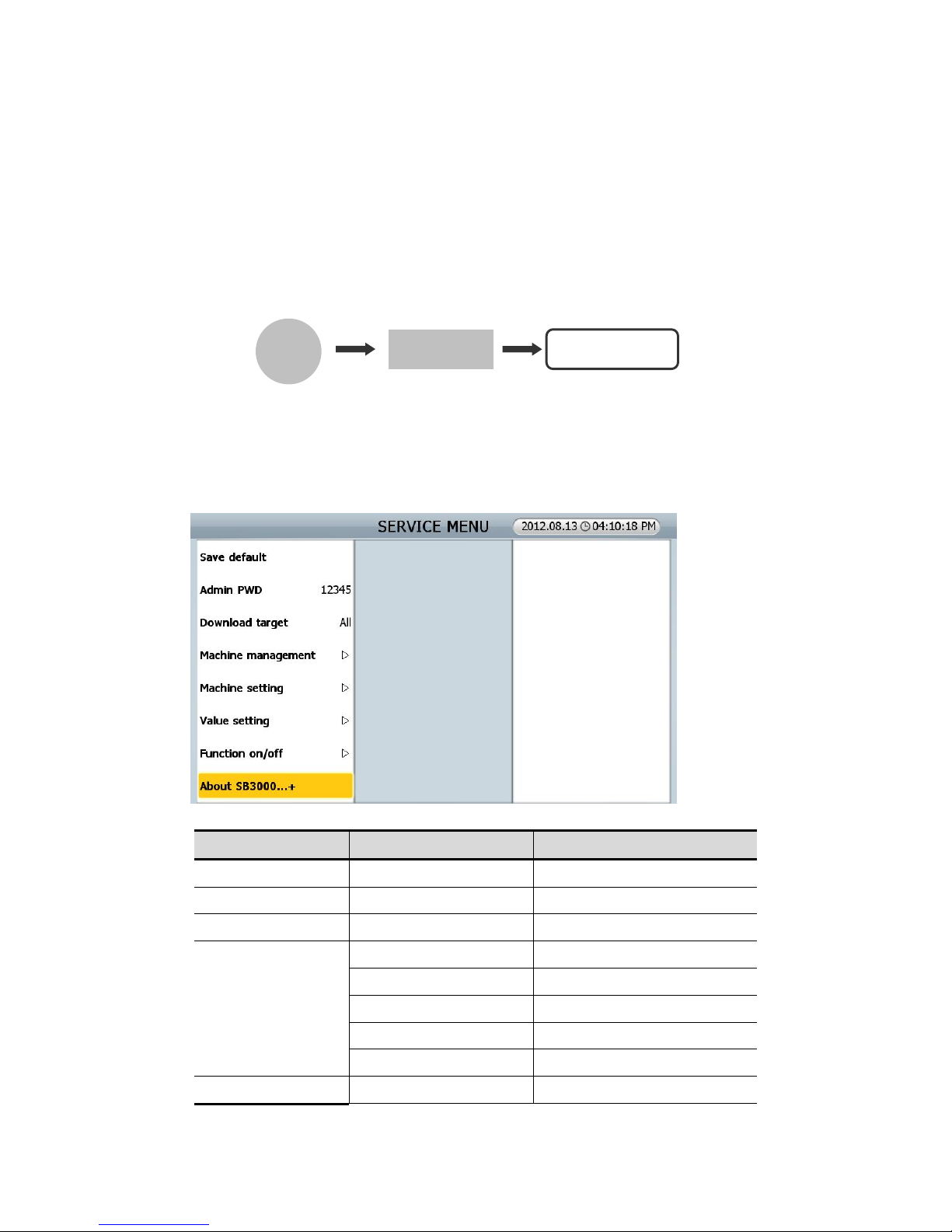
78
8.0.0. SEVICE MENU
Service engineer can download, manage, set and adjust levels in this SERVICE MENU.
You can enter SERVICE MENU as following..
[MENU] Key + [MODE] Key + CODE: *****
If you want to move to upper level or want to be out of MENU, press [C] key. If you want to set the MENU
or want to go to lower level, press [STAR/STOP] key.
If touch screen doesn’t work, connect a computer mouse to USB A.
MENU SUB MENU Description
Saving default
Admin PWD 12345
Download target All
Machine management
Program update Program
Touch Calibration Touch screen calibration
Calibration Sensor calibration
Machine test Testing machine
Log data
Machine setting Set date/time Program
MENU
MODE
CODE: *****
(FIG 8-01)
Page 79
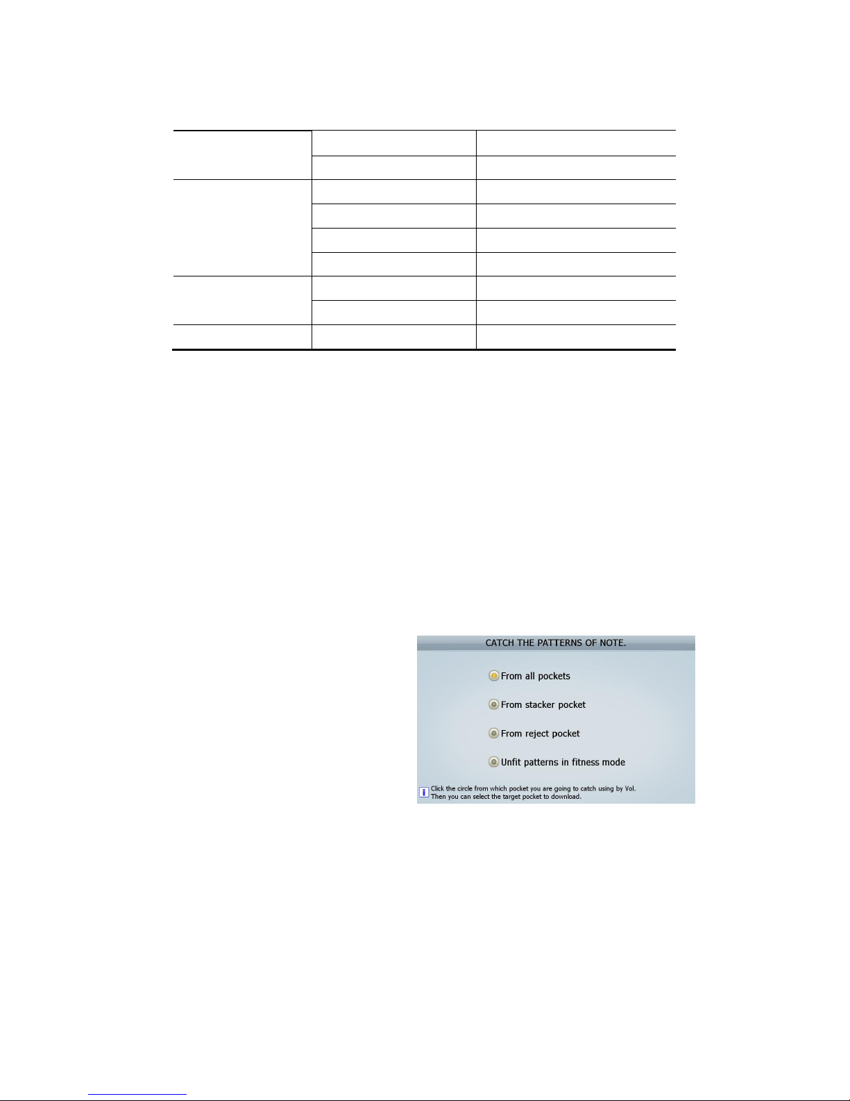
79
Set A/S call Setting A/S phone number
Ethernet Setting Ethernet
Value setting
CF level (9,9,5) Adjusting CF sensor level
Hopper level 200 Adjusting hopper sensor level
Double level (10) Adjusting double sensor level
Fitness Setting fitness function
Function on/off
CF items Setting CF detector on/off
Tape in count mode OFF Setting tape sensor on/off
About SB3000…+
8.1.0. Save default
You can reset all the parameters to initial factory level, but you cannot reset Log Data and Soil Adjust
level.
(Loading Default: Resets the level set in User Menu and Admin Menu to initial factory level.
Save default: Resets the level set in Service Menu to initial factory level.)
8.2.0. Admin PWD
Administrator password can be checked and changed at this Menu
8.3.0. Download target
You can designate the pocket for downloading
data and send the data to “Vol” program(special
program which SBM provides). Refer to the right
picture.
1. From all pockets: When you need all data in the beginning stage of developing S/W.
2. From stacker pocket: Generally when you meet misrecognition of banknotes.
3. From reject pocket: Generally when you meet misrecognition of banknotes.
4. Unfit patterns in fitness mode: Generally when you need Unfit data.
(FIG 8-02)
Page 80

80
8.4.0. Machine management
8.4.1. Program update
In this mode, user can simply install new software for upgrade by USB Memory Stick.
The steps for update are as follows.
[1] With the machine on, insert USB Memory which has the file provided from service provider to the
USB B port in the machine.
[2] Chick this menu [SERVICE MENU _ Machine management/ Program update]
[3] The machine will recognize the programs automatically.
[4] User can choose the program for update
[5] Machine will be powered off and on automatically after update is done.
[6] Regarding the formatted type of USB memory, ‘FAT32’ is recommended under the Windows
environment.
For more detail information, please refer to the Chapter 11.0.0.
8.4.2. Touch calibration
Touch calibration for screen
8.4.3. Calibration
In order that a system analyzes Reference Level and a signal of the machine, the system should
know the full swing of a waveform of a signal.
[What is the calibration?]
Calibration is to make a full swing reference waveform to read the full level of a signal. If the
machine rejects too many notes, the system might not analyze the input of waveform. It is possible
to make a standard waveform for the system. For more detail information, please refer to the
Chapter 9.0.0.
■ Batch Progress: Batch
■ MR calibration
■ Tape calibration
■ CIS calibration
■ UV calibration
You have to do the calibration on the below situation.
1. When you disassemble and assemble the sensors related
2. When you change the parts of MR/ Tape/ CIS/ UV
3. When you change the Image Board
4. When you update S/W
Page 81
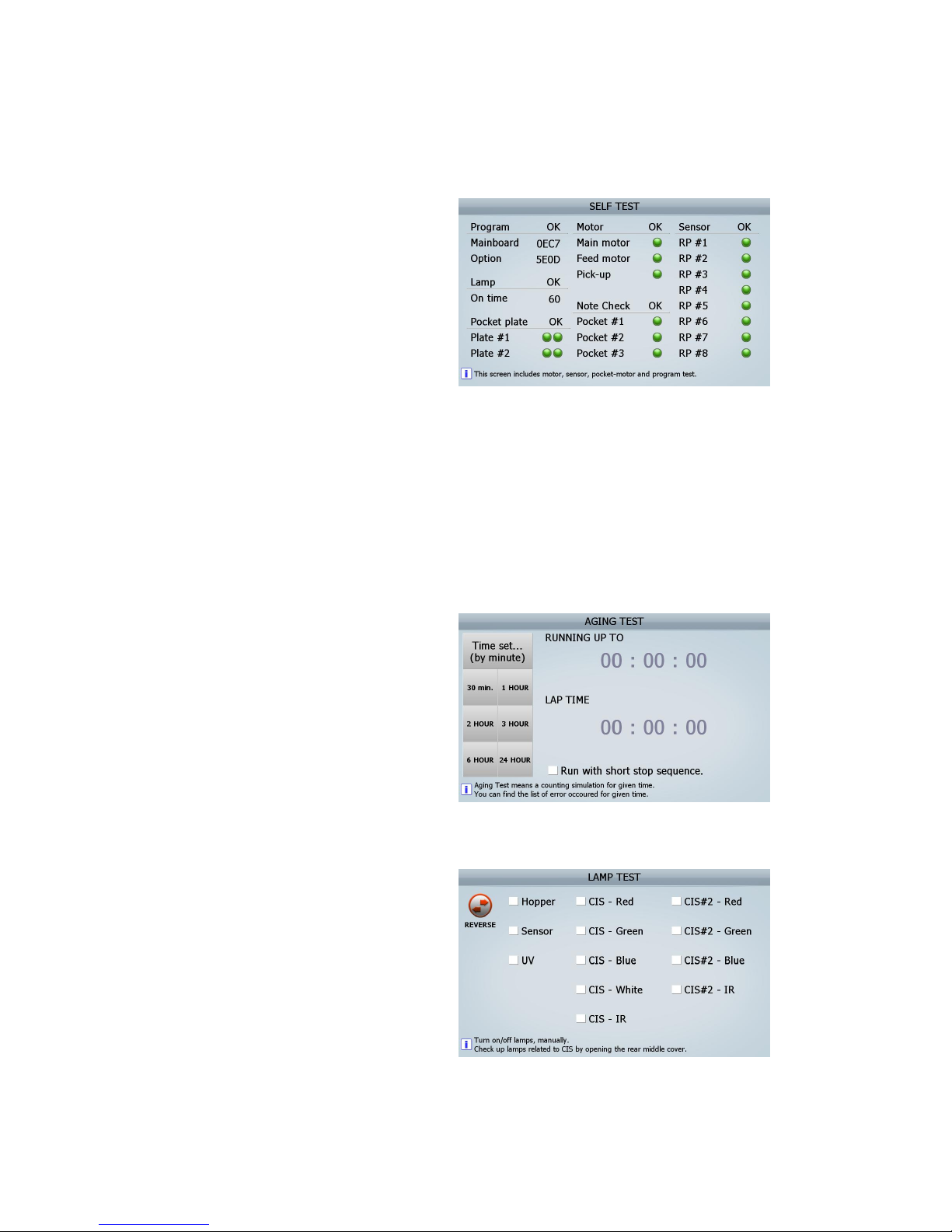
81
8.4.4. Machine test
■ Self-test
: SB-3000 have a self-test mode that motors,
sensors, pockets and program can be tested
by itself. Test result shows like right picture.
① Program: SB-3000 checks the checksum of Image Board and option Board
* If NG, update S/W once again and change the Boards (Image, Option) and test.
② Lamp: SB-3000 checks the IR transmission and White transmission.
③ Pocket plate: SB-3000 checks the Up and low Sensor of Stacker #1 & Stacker #2 Plate.
④ Motor: SB-3000 checks Main Motor, Feed motor and Pick-up Motor.
⑤ Note Check: SB-3000 checks sensors of Stacker #1, Stacker #2 and Reject Pocket.
⑥ Sensor: SB-3000 checks RP sensor.
■ Aging test
: SB-3000 runs counting test during the
period of set time. If some errors occur, you
can check them after ending this test.
* When you replace SMPS, you can take a
running test without real notes counting with
this ‘Aging test’.
■ Lamp test
: You can light the lamps manually. You can
see CIS lamp with your eyes opening the
Rear Middle Cover.
(FIG 8-03)
(FIG 8-04)
(FIG 8-05)
Page 82
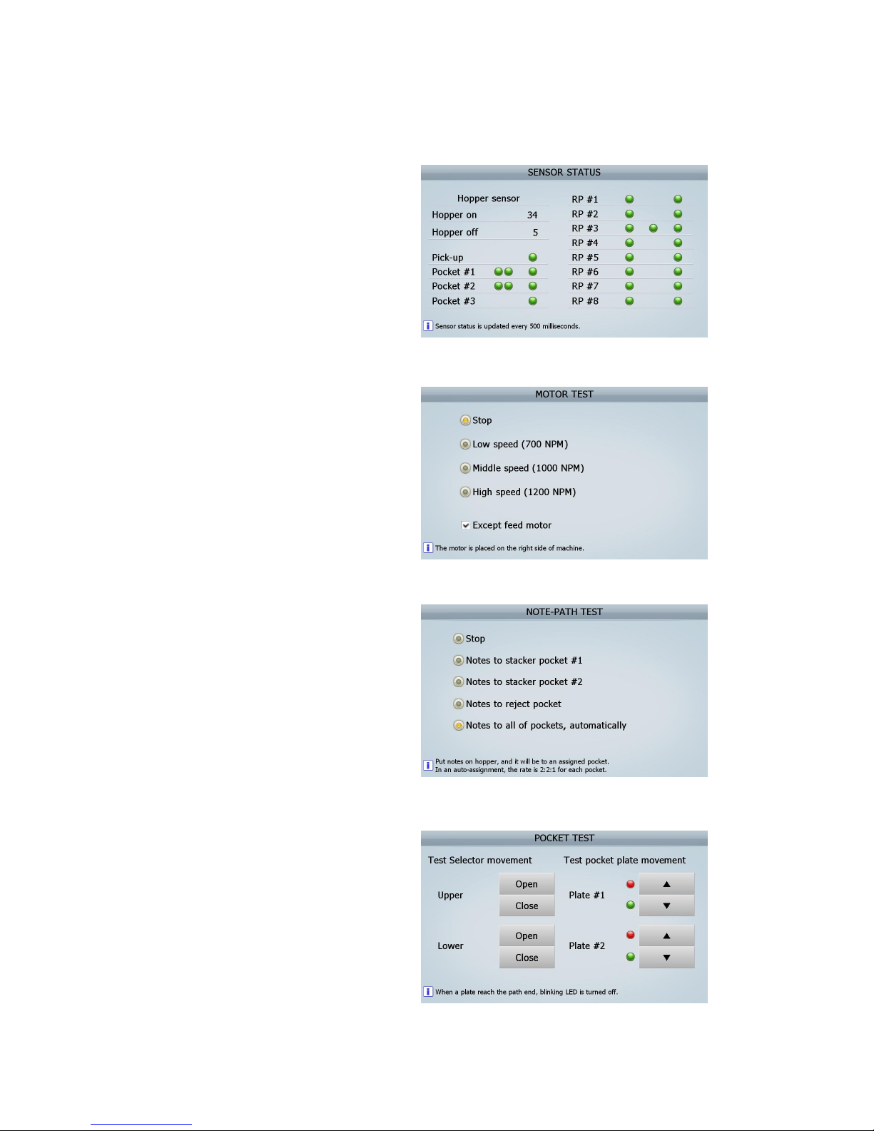
82
■ Sensor status report
: This report shows the sensor status value by
every 500ms.
■ Motor test
: You can test motor is working and the
speed.
■ Note-path test
: If you put some notes on the hopper, you
can see the notes are distributed as the
choice. If you select automatic test, the
distribution will be 2:2:1 portion.
* You can check Solenoid is working or not.
■ Pocket test
: You can check Selector movement and
Pocket plate movement. If the plate moves
to the end, LED will become red.
(FIG 8-06)
(FIG 8-07)
(FIG 8-08)
(FIG 8-09)
Page 83
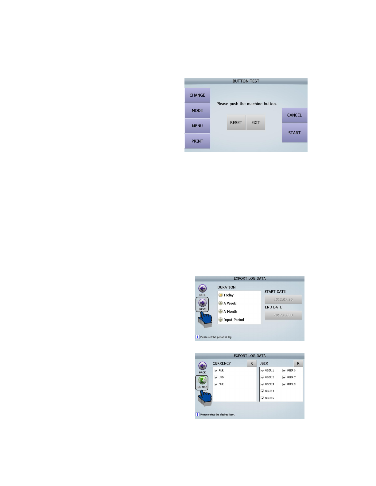
83
■Key test
: You can test keys on Control panel.
8.4.5. Log data
This mode supplies all Log DATA (Counting result Detail in Currency / Count Detail in User / Error Number
/ Upgrade Number / Calibration Number / ETC ) and provide exporting function to EXCEL file.
The procedure of Log Data Exporting is here below,
[1] Insert USB Memory Stick into the USB Port of SB-3000.
[2] Select ‘Export log data’ in this menu
(ADIMN MENU _ Log Data/ Export log Data)
[3] Select the Range of the Period.
[4] Touch on [Next] ICON.
[5] Select Currency and USER and Touch [Export] ICON.
(FIG 8-10)
(FIG 8-11)
(FIG 8-12)
Page 84
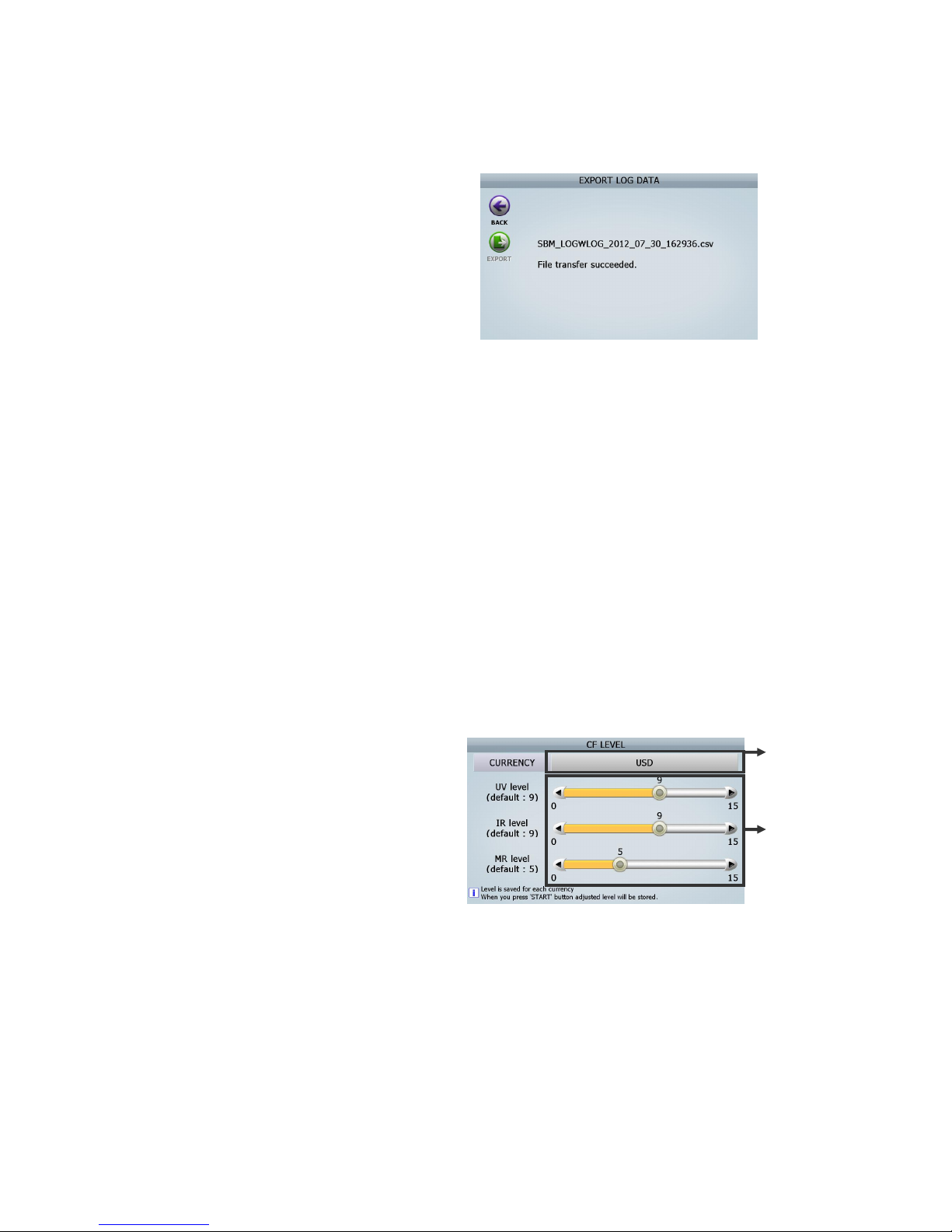
84
[6] In USB Memory Stick, Log DATA file will be
created as right screen.
8.5.0. Machine setting
8.5.1. Set date/time
8.5.2. Set A/S call: Setting A/S phone number
8.5.3. Ethernet: You can manage LAN here and can set IP address.
8.6.0. Value setting
8.6.1. CF level
In this menu, Service Man can set the levels such as UV (Ultra-Violet) Sensor, MR (Magnetic Reader)
Sensor and IR (Infrared) Sensor required detecting each currency. The setting method is as follows.
[How to set]
[1] Select Currency. (ⓐ)
[2] Move each circle and set the levels (ⓑ)
Move the circle of the first bar and set UV level. ①
Move the circle of the second bar and set IR ②
level.
Move the circle of the third bar and set MR ③
level.
(It is possible to set each level in detail by using “ ” key)◀▶
[3] Press [START/STOP] Key to save the level.
The lower number is less sensitive. If the machine detects CF note as real notes, increase level by one to
set the level. If the machine detect real note as CF note, decrease level by one to set the level.
If the level is ‘0’ (Zero), the sensor is deactivated.
ⓐ
③
(FIG 8-13)
(FIG 8-14)
Page 85
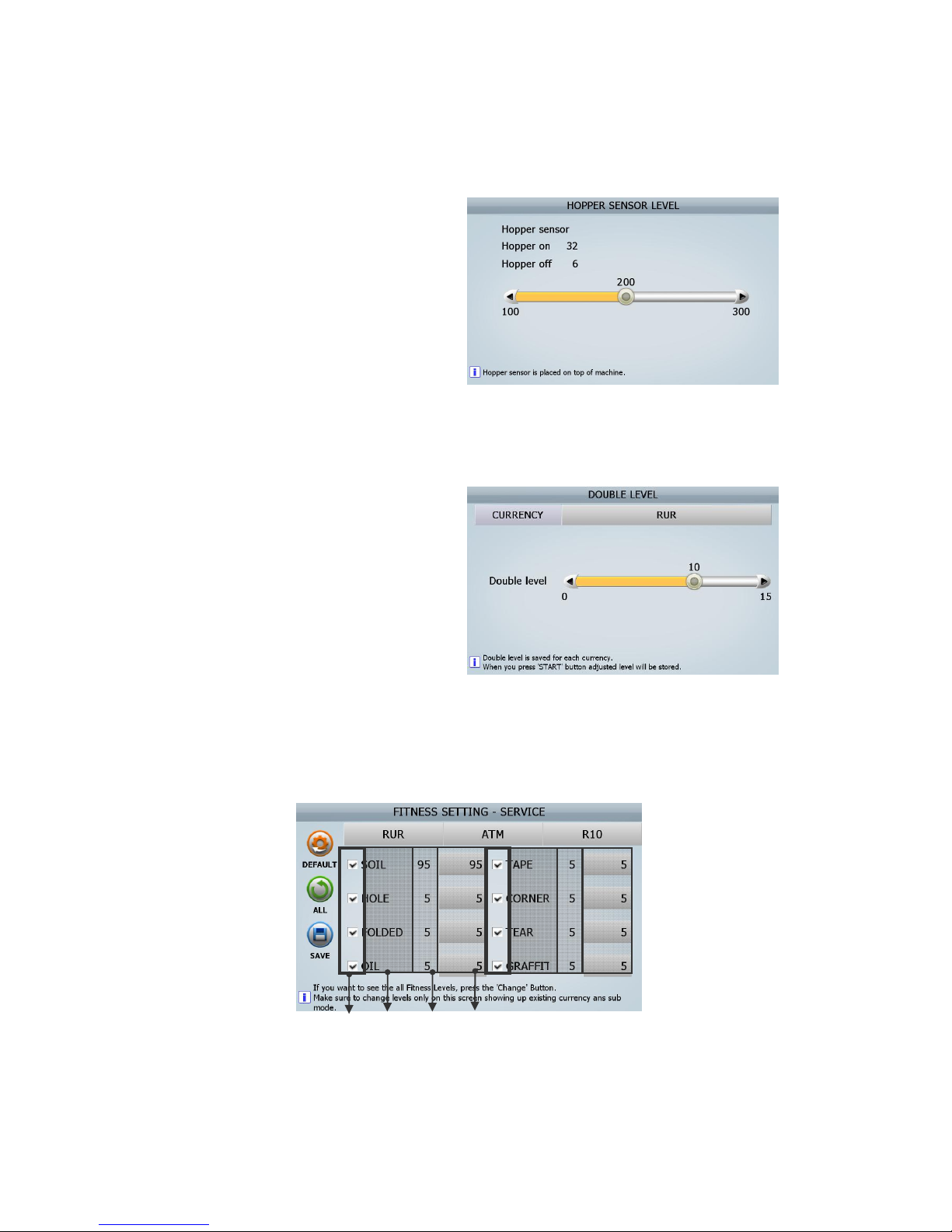
85
8.6.2. Hopper level
If the machine does not detect it, even though
there are notes on the Hopper, Lower the level
(Default-200)
* If the level is not within acceptance, you can
change the value by controlling the adjustable
resistance.
8.6.3. Double level
If the machine detects one note as Double, lower
the level. If the machine does not detect Double
notes, raise the level. (Default-10)
Double level needs to be set for each currency.
8.6.4 Fitness
■ Fitness parameter
In this menu, user can set fitness sorting level for each currency and each denomination.
① [DEFAULT]: Set Fitness value to the Default
-. [YES]: Apply to all Fitness Sub-mode
(FIG 8-15)
(FIG 8-16)
④ ⑤ ⑥
⑧ ⑨⑦
②
①
⑩
(FIG 8-17)
Page 86
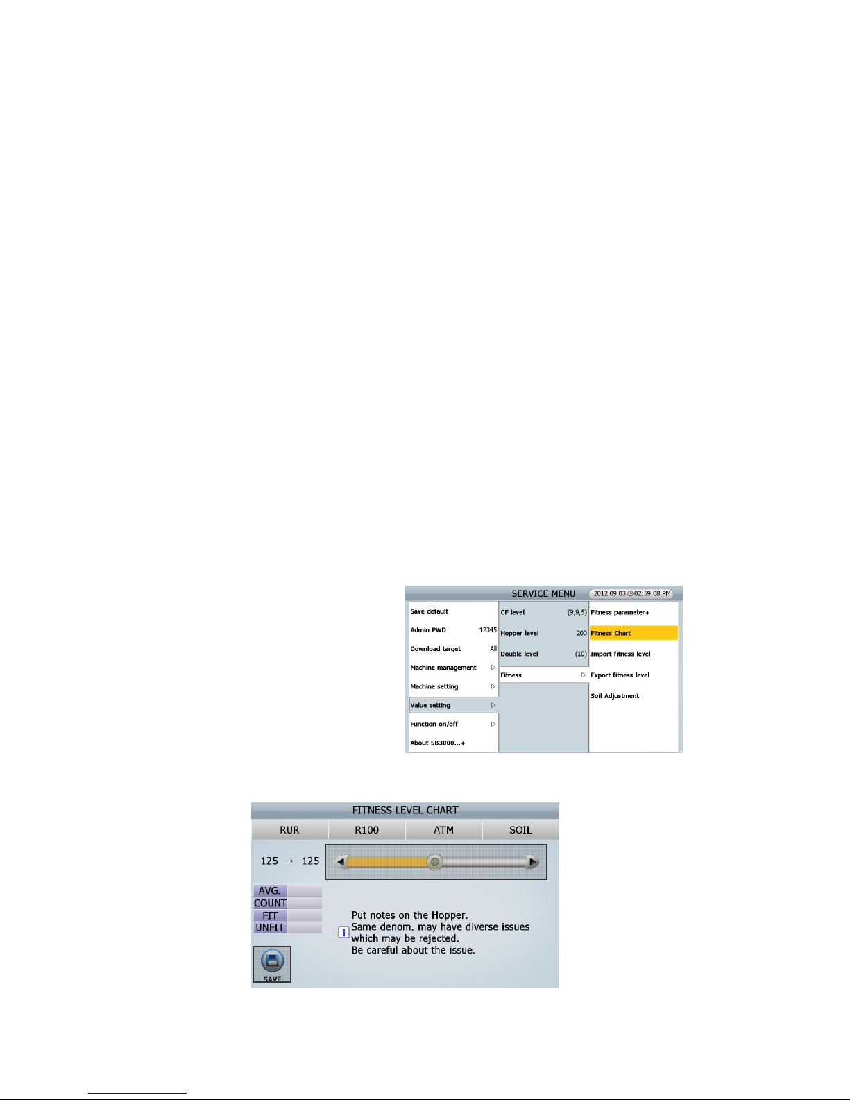
86
-. [NO]: Apply only to current Fitness Sub-mode
-. [CANCEL]: Do not apply
② [ALL]: Decide if the data below is also applied or not to another denomination.
-. Fitness Levels & On/Off set
-. Fitness Levels
-. Fitness On/Off set
③ [SAVE]: Save current setting (Currency, Fitness Sub-mode, Denomination)
[CURRENCY]: The current currency’s displayed and if this is touched, another currency is set.④
[Fitness Sub⑤ -Mode]: The currency Fitness Sub-Mode is displayed and if this is touched, another Fitness
Sub-Mode is set.
[Denomin⑥ ation]: The currency denomination is displayed and if this is touched another denomination is
set.
⑦ [Setting value]: Setting On or Off on each condition,
If it is off, that condition doesn’t apply to other denominations.
⑧ [Fitness Sorting]: Items for fitness are displayed
[Default]: The default of each item is displayed. ⑨
⑩ [Current value]: The current value for each item is displayed/
■ Fitness chart
You can check and set the portion of Fit & Unfit
notes distribution by the items.
How to set FITNESS LEVEL CHART
④
⑤
②① ③
⑥
(FIG 8-18)
Page 87
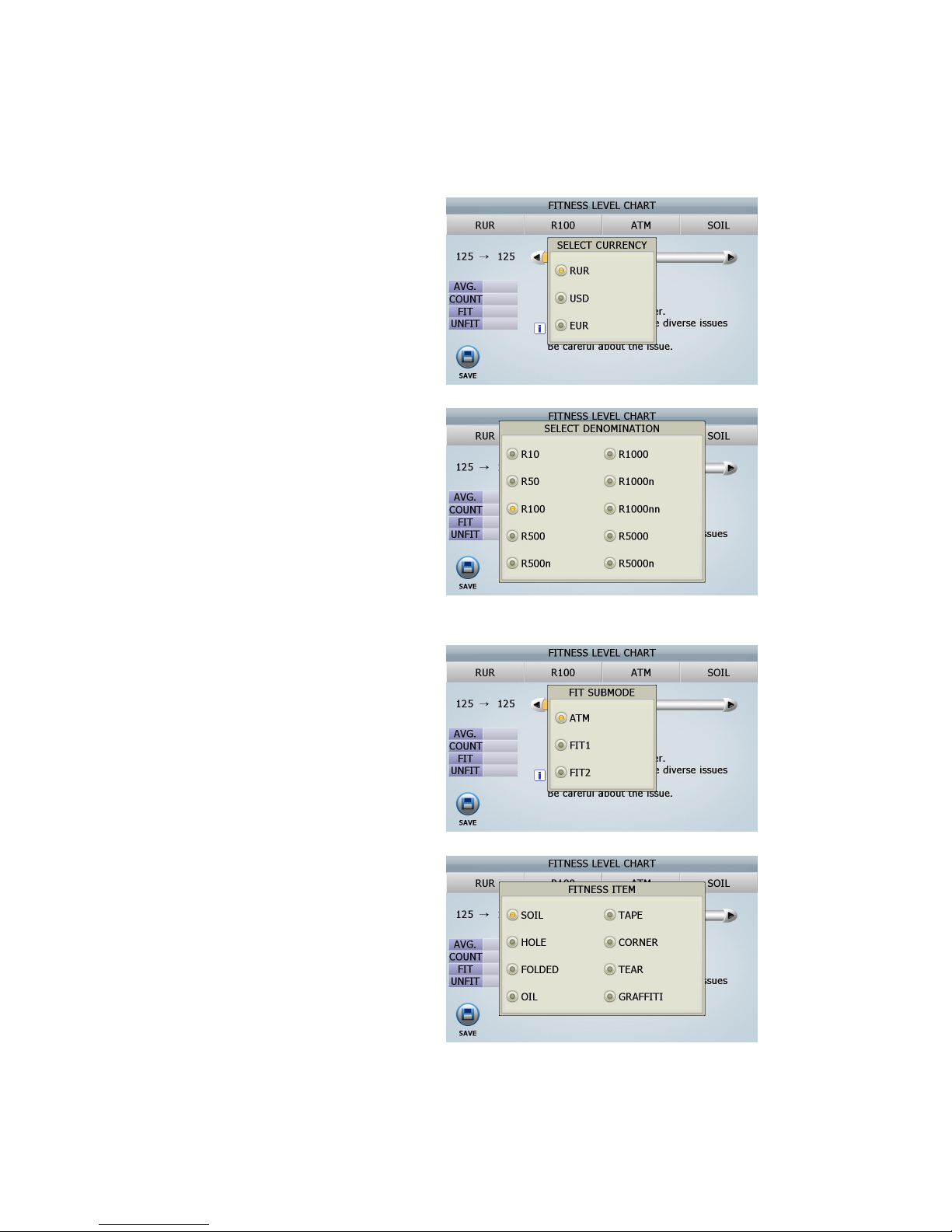
87
[1] Setting of the basic contents for adjusting the Fitness Level
- CURRENY: Setting of the currency by
touching the section (①)
- DENOMINATION: Setting of
denomination by touching the section
(②)
- SUB MODE: Setting of Sub mode in
Fitness by touching the section (③)
- Fitness condition: Setting of Fitness
condition by touching the section (④)
[2] For example, prepare total 100 notes of RUB 100 with same denomination and same orientation.
(FIG 8-19)
(FIG 8-20)
(FIG 8-21)
(FIG 8-22)
(FIG 8-23)
Page 88
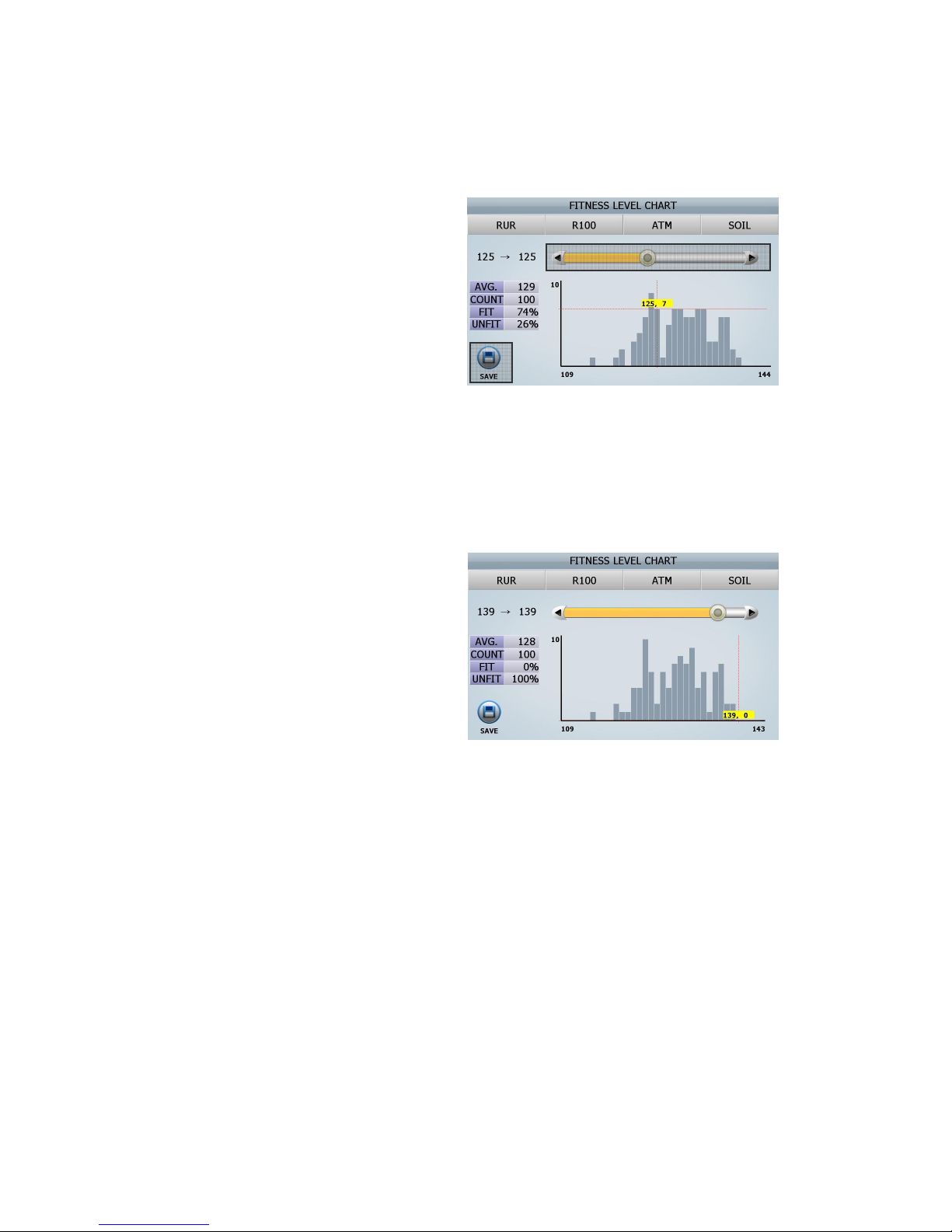
88
And place them on the hopper
[3] After counting, the screen will be shown as
right
- AVG.: the average of soil level
- COUNT: the number of notes
- FIT: the percentage of fit notes
- UNFIT: the percentage of unfit notes
[4] As you can see the screen, Service Man can change this level in this menu by dragging it (⑤)
[5] If User want to adjust the soil level in order to process all of 100 notes as unfit ones, Find the highest
number of in the FIT range, in this case, it will be the level, 139
[6] If the level 139 is entered, Initial processed
100 notes are automatically distributed to the
level in the UNFIT range.
By touching the section (⑥) or pressing the
[START/STOP]key, adjusted soil levels are
applied.
From now on, all of 100 notes will be processed
as UNFIT ones.
■ Import fitness level
■ Export fitness level
You can apply the specified fitness level from one machine to another by Import fitness level & Export
fitness level Menu. This is how to export the specified fitness level and how to import.
Follow the below steps
[1] Insert USB Memory Stick to USB port in SB-3000
[2] Select ‘Export fitness level’ in this menu
⑤
⑥
(FIG 8-24)
(FIG 8-25)
Page 89
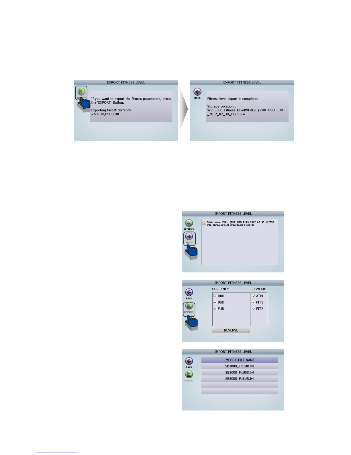
89
(ADIMN MENU _ Value setting/ Fitness/ Export fitness level)
[3] Touch on [EXPORT] Icon. Then LCD will be displayed as follows
[4] The file is created in USB memory stick.
(File folder name: SB3000_Fitness_Level)
[5] Insert USB Memory Stick, which has ‘SB3000_Fitness_Level’ folder, to another SB-3000 that
supervisor want to input previously fitness level to.
[6] Select ‘Import fitness level’ in this menu.
(ADIMN MENU _ Value setting/ Fitness/ Import fitness level)
[7] LCD of another SB-3000 will be displayed as
follows
-1 After checking the file which you want to apply to
another SB-3000. And then touch [NEXT] Icon
-2. Select the currencies and fitness Sub-Mode which
supervisors want to apply to another SB-3000. And
touch [IMPORT] Icon
-3. Finish
(FIG 8-26)
(FIG 8-27)
(FIG 8-28)
(FIG 8-29)
Page 90
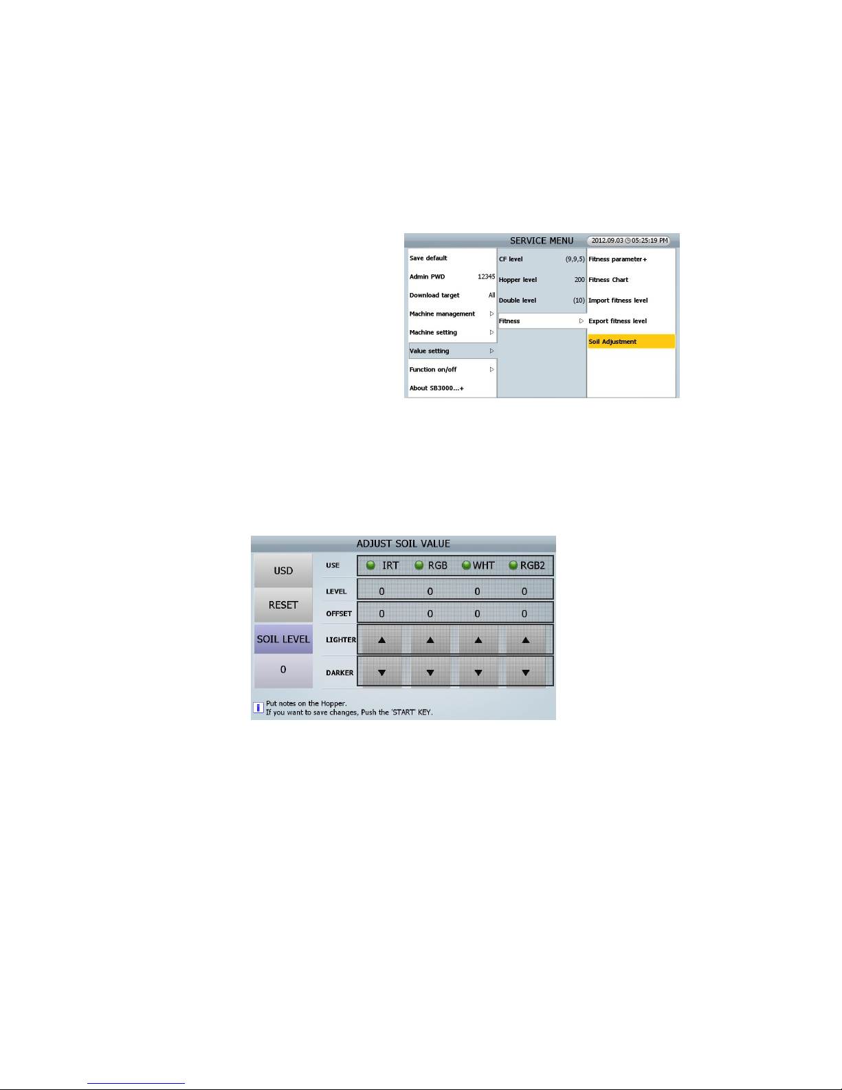
90
[8] Finishes
■ Soil adjustment
1. Explanation
1) Due to tolerance between SB-3000, each
machine has the different sorting level
even if same soil level is set
2) To correct this tolerance between SB-3000,
“ADJUST SOIL VALUE” menu in service
mode has been added
3) In this menu “ADJUST SOIL VALUE”, it is
possible to manually adjust the quantity of
IR, RGB, WHT, and RGB 2 to reduce the tolerance
4) For example, When the Image or Option Board are changed or CIS sensors are changed, the Soil
level need to be adjusted in order to reduce to the tolerance between the sets.
2. MENU
① CURRENCY: Currency which needs correction of the tolerance of SOIL LEVE
In SB-3000, wee use US 1$ need for ADJUST SOIL VALUE in all currency.
② RESET: reset all adjusting offset.
③ SOIL LEVEL: key for changing value of LIGHT SOURCE
④ USE: Light Source
IRT (IR Transmission), RGB (CIS1 Reflection), WHT (WHITE), and RGB2 (CIS2 Reflection)
⑤ LEVEL: Value of each Light Source
⑥ OFFSET: the Adjusting value of each Light Source
⑦ & ⑧ LIGHTER & DARKER: Key for changing the adjusting value.
④
⑤
②
①
③
⑥
⑦
⑧
(FIG 8-30)
(FIG 8-31)
(FIG 8-32)
Page 91
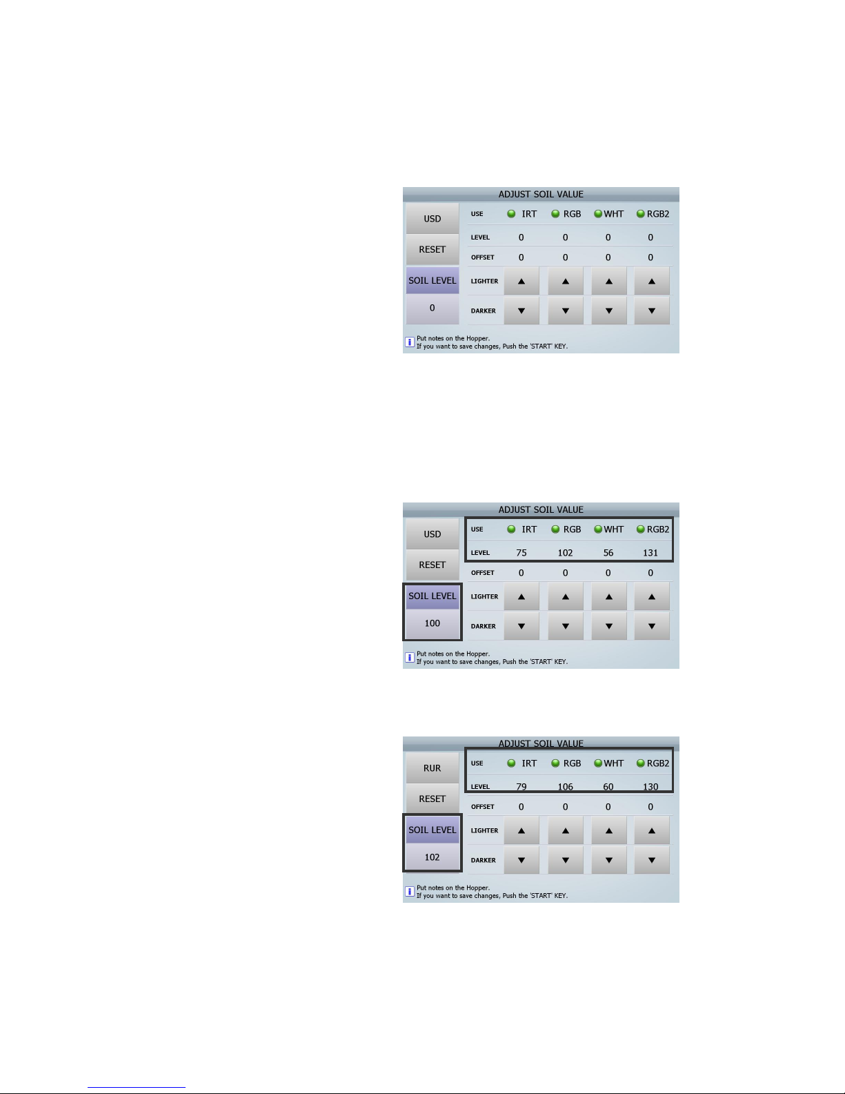
91
3. How to adjust
1) Press “ MENU -> MODE -> ***** ->
VALUE_FITNESS_SOIL ADJUSTMEN”,. Then,
The Screen will be displayed as below
2) Adjust Bill Guide and place one standard note (US 1$).
- When adjusting the soil level in the machines, you have to put the standard note with same direction
- The quality of the note shall be Fit note.
3) The picture as right shows the result after
placing US 1$ into the standard machine (No 1
machine).
You can see the below data
- IRT level: 75
- RGB level: 102
- WHT level: 56
- RGB2 level: 131
- SOIL LEVEL: 100
4) The picture as right shows the result after
placing US 1$ into another machine (No 2
machine).
You can see the below data.
- IRT level: 79
- RGB level: 106
- WHT level: 60
- RGB2 level: 130
- SOIL LEVEL: 102
(FIG 8-33)
(FIG 8-34)
(FIG 8-35)
Page 92
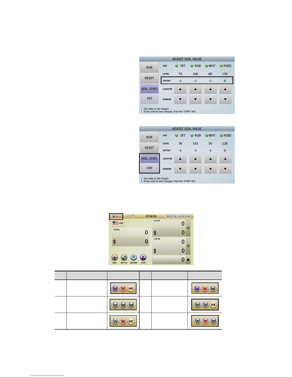
92
5) Soil level in No2 Machine is higher than in
No2 machine. So, decrease value of Light
source by using key (LIGHTER & DARKER) to
make Soil level same in two machines. As you
can see the picture () value of IRT, RGB, and
WHT are decrease by 1.
Then, you can see soil level is “100” in No 2
machine like No 1 machine.
8.7.0. Function on/off
8-7-1 CF items
Administrator can set CF On/Off and can set sensors (UV, MR, IR) individually.
No Sensors status Indicator No Sensors status Indicator
1
CF on
(UV, IR, MR on)
5
MR off
UV on, IR on
2
CF off
(UV, IR, MR off)
6
UV off, IR off
MR on
3
UV off
IR on, MR on
7
UV off, MR off
IR on
(FIG 8-36)
(FIG 8-37)
(FIG 8-38)
Page 93
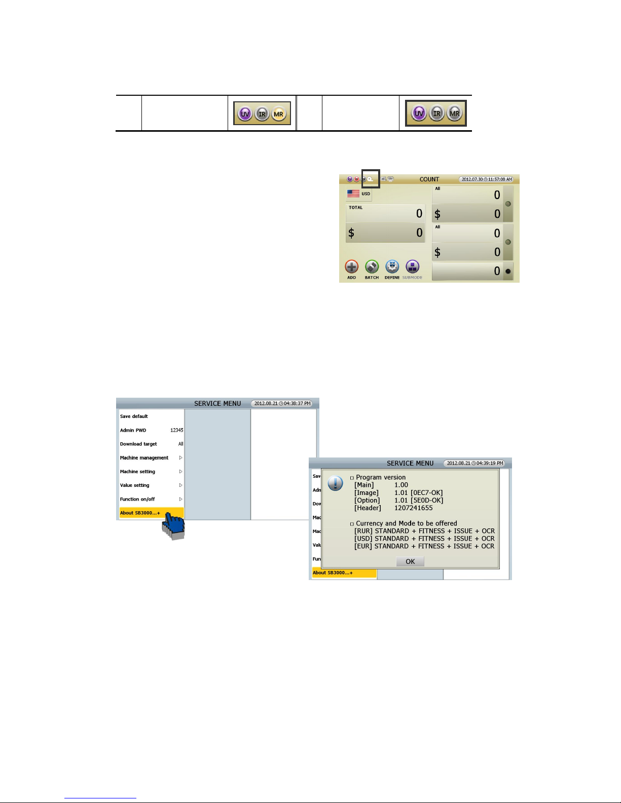
93
4
IR off
UV on, MR on
8
IR off, MR off
UV on
8-7-2 TAPE in count mode
Can set Tape Sensor ON/Off here, except for Fitness Mode.
In case of Fitness Mode, should set Tape sensor in
Fitness setting.
Tape function On, Tape indicator will be shown like right
picture (FIG 6-18).
8.8.0. About SB3000…+
In this menu, you can check the Program version and Currency and Mode to be offered.
(FIG 8-39)
(FIG 8-40)
(FIG 8-41)
Page 94
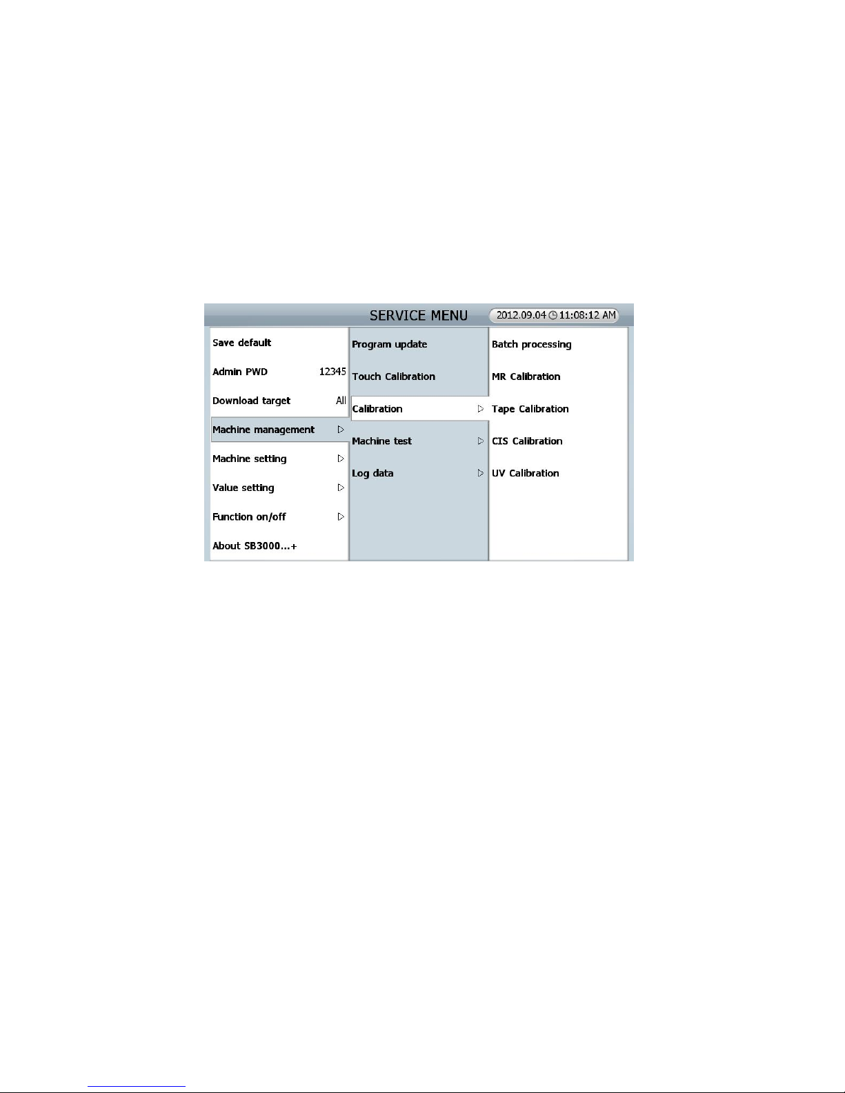
94
9.0.0. CALIBRATION
WHAT IS THE CALIBRATION?
Calibration is to make a full swing reference waveform to read the full level of a signal. If the machine
rejects too many notes in CF Detection Mode, the system might not analyze the input of waveform. It is
possible to make a standard waveform for the system.
ATTENTION
Before doing calibration, make sure to clean all sensors.
Then, please carry out ‘LOADING DEFAULT’ in ADMIN MENU as following order
(FIG 5-01)
Page 95
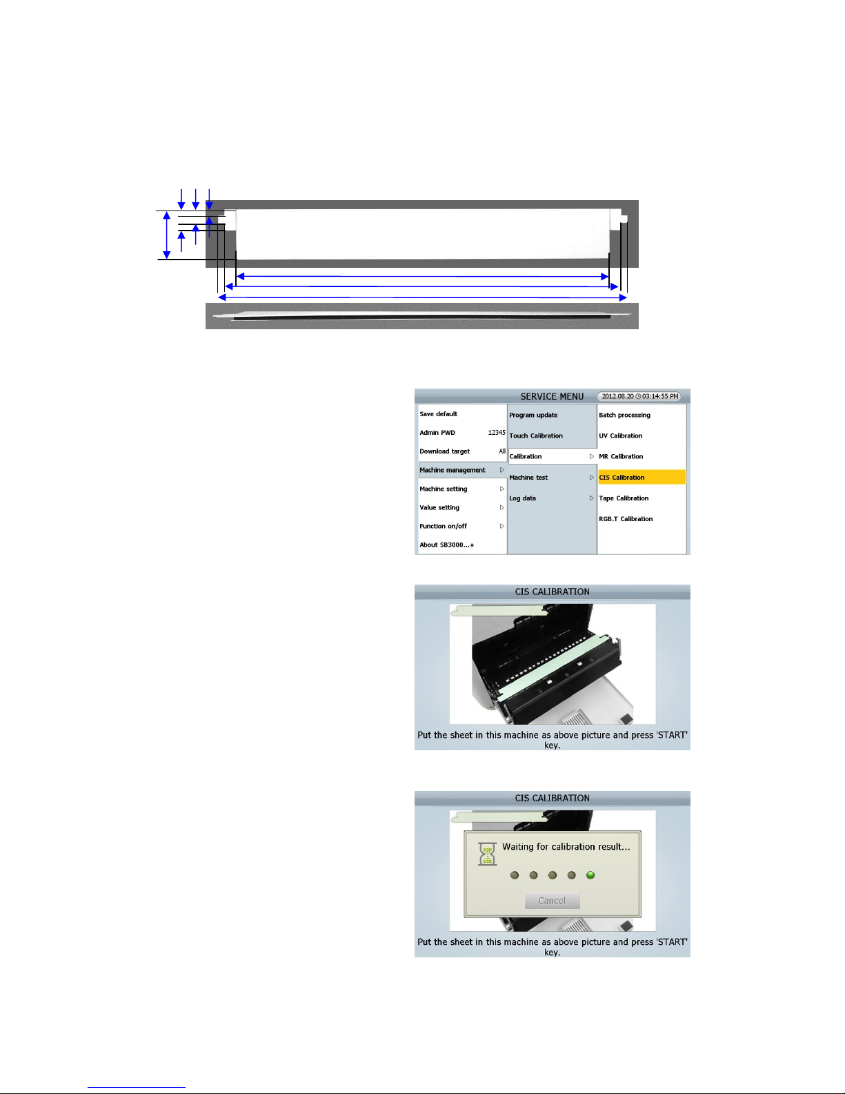
95
9.1.0 CIS Calibration (IMAGE Calibration)
This CIS Calibration is for CIS Sensors.
CIS Calibration Sheet (opaque)
[Procedure]
[1] Touch on CIS Calibration MENU
[SEVICE MENU _ Machine management/
Calibration/ CIS calibration]
[2] Open the REAR DOOR B, and Open the
REAR MIDDLE COVER
[3] Put the sheet in this machine as right picture
[4] Close the REAR MIDDLE COVER and Close
the REAR DOOR B
[5] Press [START/STOP] Key
(FIG 9-10)
(FIG 9-11)
(FIG 9-12)
(FIG 9-13)
228
220.8
206
27.2
11.7 7.6 3.6
Page 96
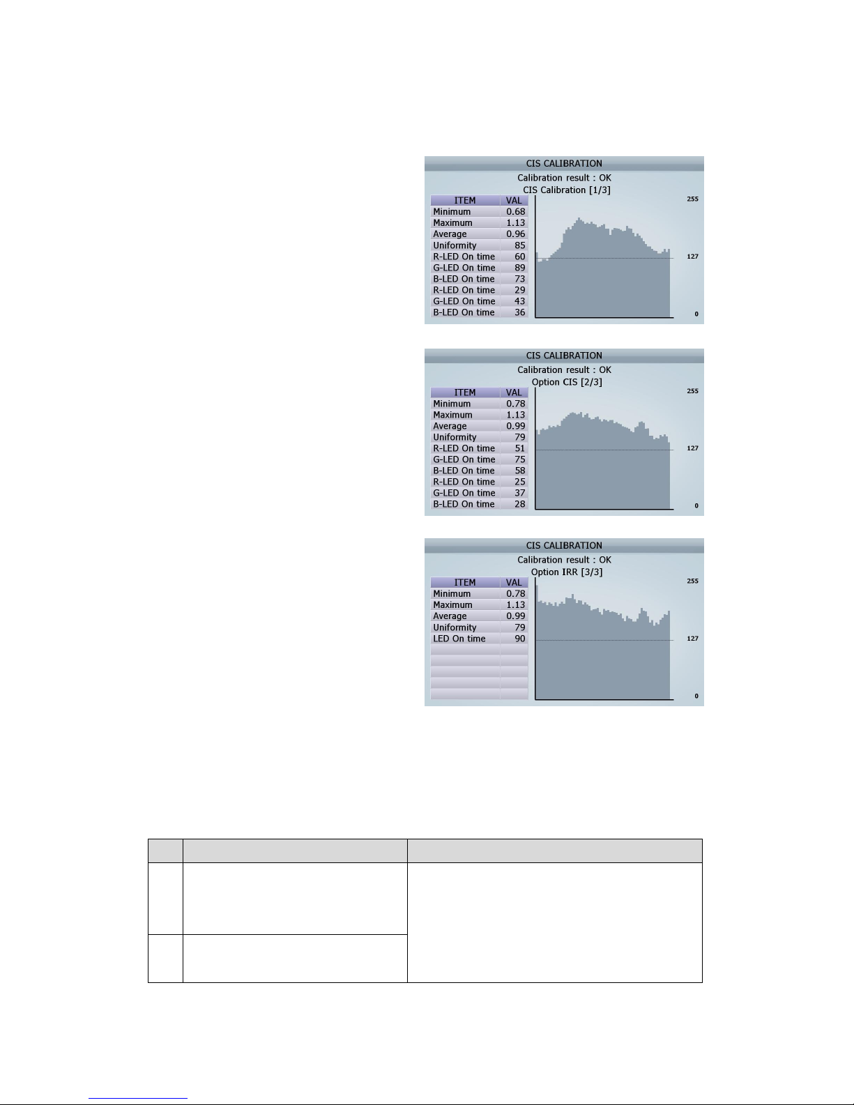
96
[6] Check if CIS Calibration result is “OK” or “NG”
① The result of CIS Calibration
② The result of Option CIS Calibration
② The result of Option CIS IRR Calibration
[7] After doing calibration, Open the Rear Door B and the Rear Middle Cover, and then take out the sheet.
[The detail information for CIS Calibration’s NG]
No.
The Cause expected Action to be taken
1
Min NG: If the number of calibration
whose value is lower than 65% of
average is more than 40
1. Need to clean CIS sensors (CIS1 and Opt CIS)
2. Need to check CIS’s defect
3. Need to check Image board’s defect
2
Average NG: if the average voltage is
more than 1V ± 10%.
(FIG 9-14)
(FIG 9-15)
(FIG 9-16)
Page 97
97
3
Average NG: if the average voltage is
more than 1V ± 10%.
1. Need to clean CIS sensors (CIS1 and Opt CIS)
2. Need to check CIS’s defect
3. Need to check Image board’s defect
4
Uniformity NG: If the uniformity is less
than 65%
5
NG if each R.G.B On time is more than
150.
6
NG if all R.G.B On time is 255
▶ Even if the all of pixel is on, target
voltage couldn’t be achieved.
Need to check the CIS receive sensor
Page 98
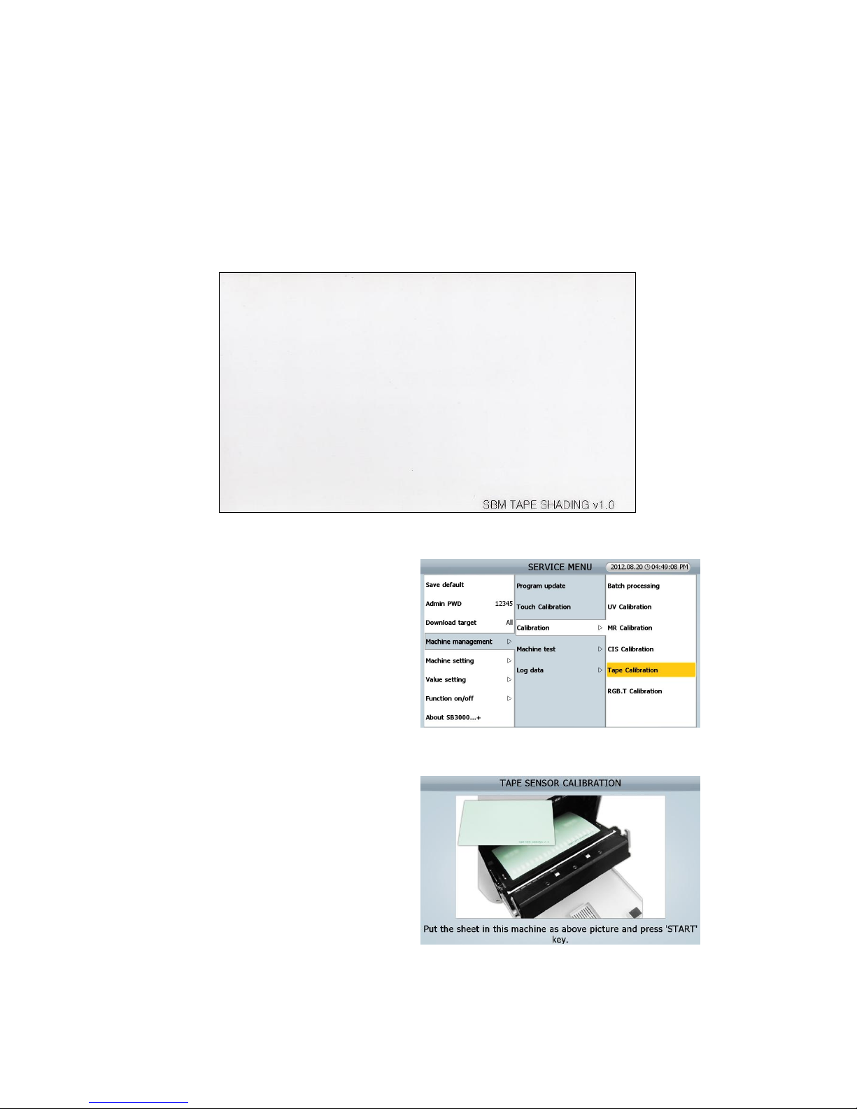
98
9.2.0. TAPE Calibration
This Tape Calibration is for Tape Sensors.
You should use the Tape calibration sheet provided from SBM as below
<CAP SHADING SHEET>
(180x 105 mm)
[Procedure]
[1] Touch on TAPE Calibration MENU
[SEVICE MENU _ Machine management/
Calibration/ TAPE calibration]
[2] Open the REAR DOOR B, and Open the REAR MIDDLE COVER
[3] Put the sheet in this machine as right picture
[4] Close the REAR MIDDLE COVER and Close the REAR DOOR B
(FIG 9-06)
(FIG 9-07)
(FIG 9-08)
Page 99
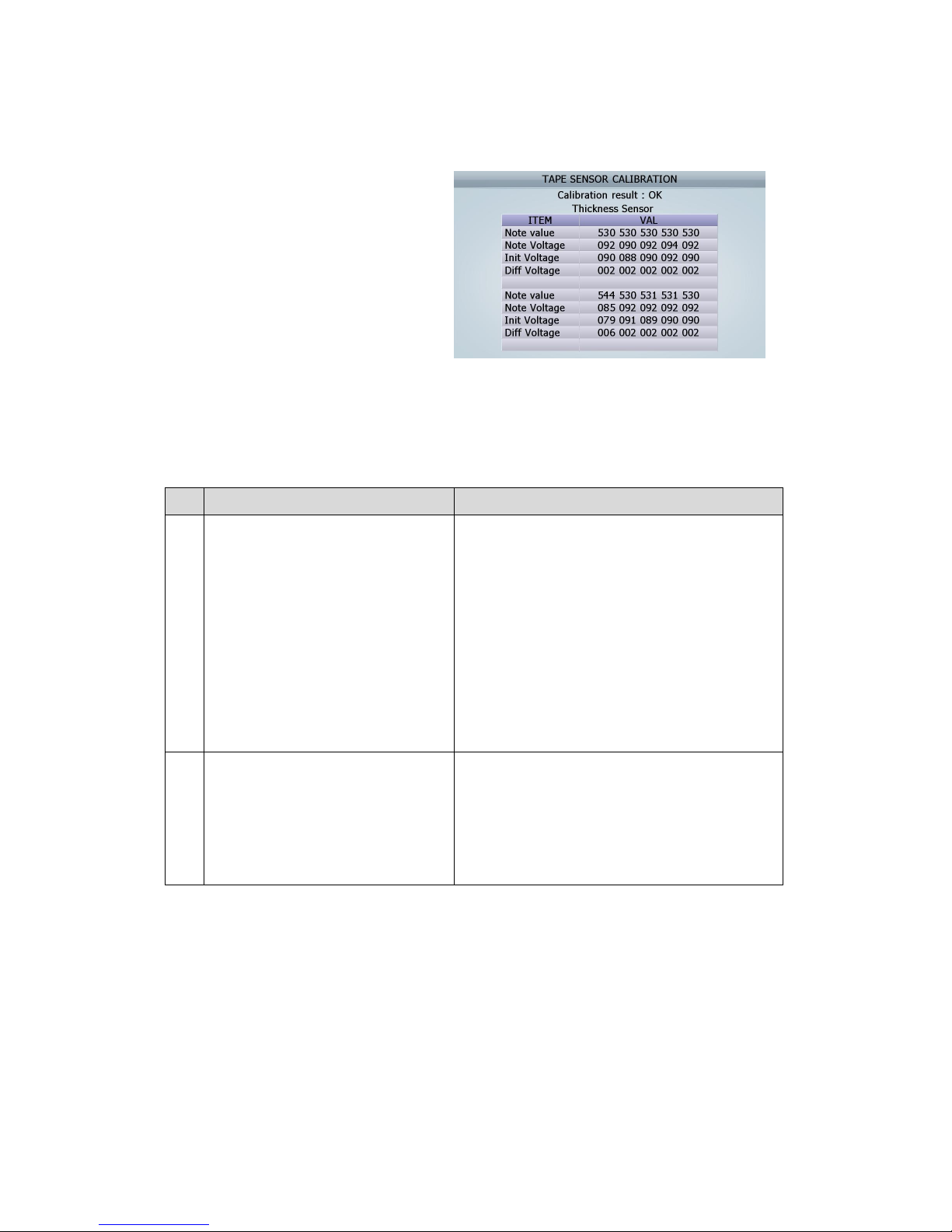
99
[5] Press [START/STOP] Key
[6] Check if TAPE Calibration result is “OK” or
“NG”
[7] After doing calibration, Open the Rear Door B and the Rear Middle Cover, and then take out the sheet.
[The detail information for TAPE Calibration’s NG]
No.
The Cause expected Action to be taken
1
The standard value of TAPE
calibration is 550 (tolerance ± 20)
▶ The calibration result is verified
with the value of each channel; in
case of NG the value is reversed like
the NG display figure. Even one of 10
channels has more or less than the
standard value (550 ±20), the
calibration is NG
1. Need to clean Tape sensors
2. Check the condition of module assembly
3. Check the CAP RCV board
2 All of Diff voltage is 0
1. Check whether the calibration sheet is in place.
2. Check harness cut off or disconnected MTU board
and CAP RCV PCB or MTU board and Image
Board
3. Need to check the defect of TAPE sensor
(FIG 9-09)
Page 100
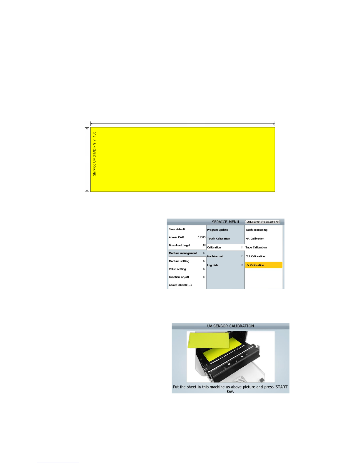
100
9.3.0. UV Calibration
This UV Calibration is for UV Sensors.
You should use the UV calibration sheet provided from SBM as below
<UV SHADING SHEET: SHINWOO UV SHADING V1.0>
[Procedure]
[1] Touch on UV Calibration MENU
[SEVICE MENU _ Machine management/
Calibration/ UV calibration]
[2] Open the REAR DOOR B, and Open the REAR MIDDLE COVER
[3] Put the sheet in this machine as right picture
165 mm
75 mm
(FIG 9-17)
(FIG 9-18)
(FIG 9-19)
 Loading...