

Page 1
GAS INFRARED HEATERS
1.
PRODUCT SPECIFICATION
Pages
2 to 3
2.
INSTALLATION
Pages
4 to 13
3.
RECEIPT OF INSTALLATION
Page 14
4.
MAINTENANCE
Page
15 5.
REPAIRS
Pages
16 to
19
6.
CHANGING THE GAS USED
Page
19
SX INSTALLER INSTRUCTIONS
N° 05000045/5
1.1 Technical specifications ......................................................................... 2
1.2 SX heater dimensions ............................................................................ 3
2.1 Rules and regulations ............................................................................ 4
2.2 Diagram of a standard installation .......................................................... 4
2.3 Unpacking and checking of equipment .................................................. 5
2.4 Fixing of heaters .................................................................................... 5 to 6
2.5 Minimum safety distances ...................................................................... 7
2.6 Inclination of heaters .............................................................................. 7 to 8
2.7 Gas connection ...................................................................................... 9 to 10
2.8 Electrical connections ............................................................................ 10 to 11
2.9 Start-up .................................................................................................. 12 to 13
Manufacturer : Agent :
SBM
3 cottages de la Norge
21490 CLENAY - FRANCE
1
Page 2
B6
B8
B10
B12
B16
B20
B20
B24
B24
B32
B32
B64
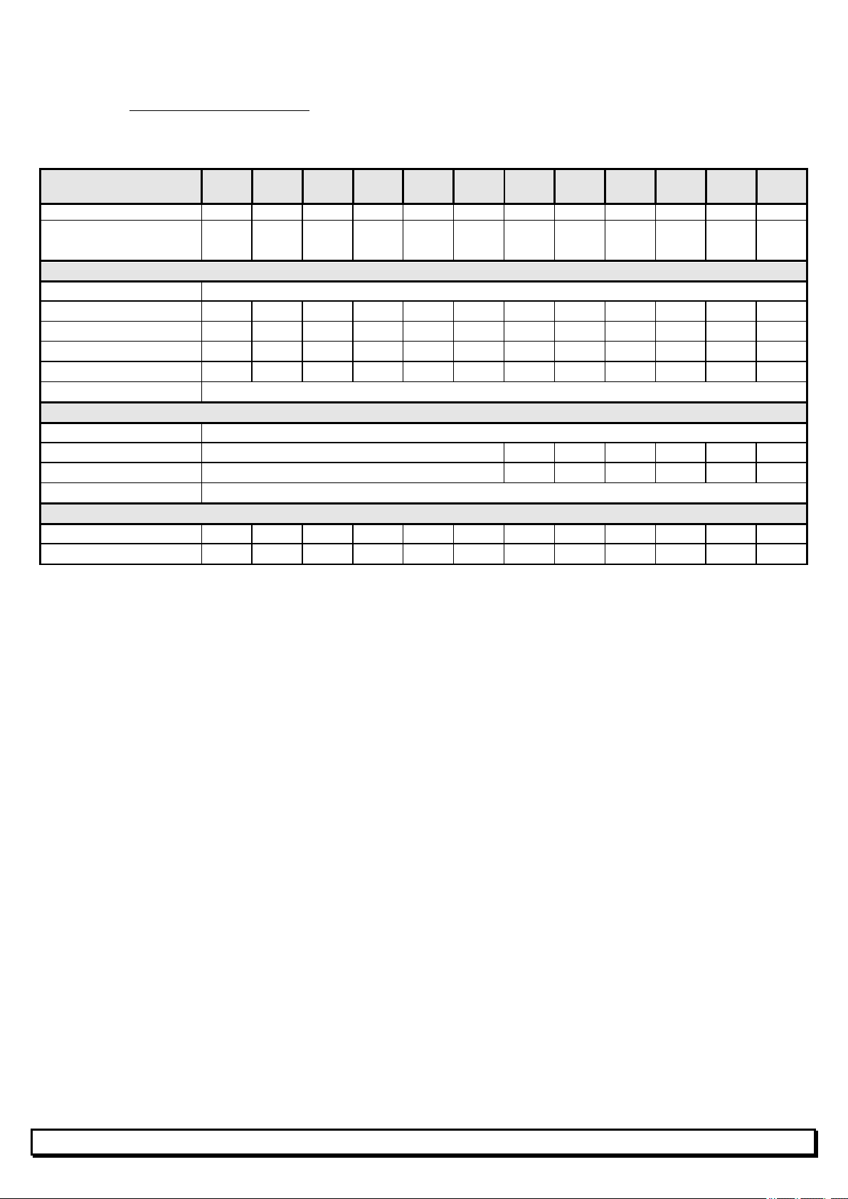
1. PRODUCT SPECIFICATION
1.1 Technical specifications :
GAS : Air / Butane (Hi = 10.5 kWh/m3)
MODEL
Weight (kg)
Net calorific value
Qn (kW) Hi
SX
SX
3.1 4.1 5.0 6.7 12.2
3.80 6.75 7.60 13.50 27.00
SX
SX
SX
SX
2SX
SX
2SX
SX
2SX
2SX
GAS
Inlet pressure 37 mbar
Injection pressure (mbar)
Gas consumption (kg/h)
Ø prim. Inject. (1/100 mm) 155 210 220 320 2x320
Ø sec. Inject. (1/100 mm) 240 300 2x240 2x300 4x300
Gas input connection Fitting 12G (G1/2" cylindrical)
5 7 5 7 7
0.645 1.145 1.290 2.290 4.580
ELECTRICITY
Power supply 230V (+10% -15%) - 50Hz Neutral mandatory
Consumption 0.1A 2x0.1A 0.1A 2x0.1A 0.1A 2x0.1A 2x0.1A
Individual fuse 0.25A 2x0.25A 0.25A 2x0.25A 0.25A 2x0.25A 2x0.25A
Ignition cycle length 45 seconds
VENTILATION
Combustion air (m3/h)
Req. air change (m3/h)
4.83 8.57 9.66 17.15 34.30
38 67.5 76 135 270
2
Page 3
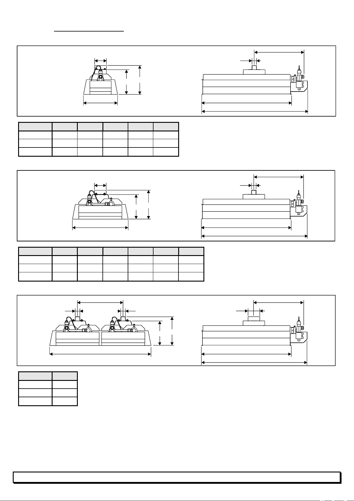
1.2 SX heater dimensions :
B6, B8, B10, B12 and B16 SX
70
172
147
A
26
202
MODEL B6-SX B8-SX B10-SX B12-SX B16-SX
A (mm)
B (mm)
C (mm)
186 218 243 281 299
222 285 334 411 536
318 382 431 508 632
B20, B20-2, B24, B24-2, B32 and B32-2SX
70
172
147
332
MODEL B20-SX B20-2SX B24-SX B24-2SX B32-SX B32-2SX
A (mm)
B (mm)
C (mm)
243 243 281 281 299 299
334 334 411 411 536 536
431 431 508 508 632 632
B64-2 SX
272
26
26
B
C
A
26
B
C
A
70
172
147
604
B
C
MODEL B64-2SX
A (mm)
B (mm)
C (mm)
299
536
632
3
Page 4
junction box
with ground)
2. INSTALLATION
2.1 Regulations
THESE HEATERS MUST BE INSTALLED IN ACCORDANCE WITH APPLICABLE
REGULATIONS AND IN WELL VENTILATED PREMISES.
The ideal level of ventilation for the premises is 10 m3/h per kW of heating installed.
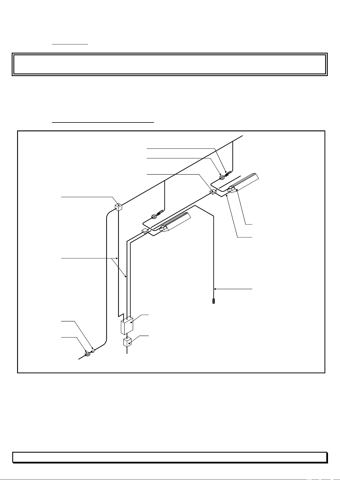
2.2 Diagram of a standard installation.
Individual valve
Regulator
Electrical
Solenoid valve
Electrical cable
(3-conductor insulated
Gas filter
Main valve
Gas supply
SBM infrared heater
Prewired plug
Sensor
Control unit
RCD (Residual Current Device
230V - 50Hz
4
Page 5
2.3 Unpacking and checking of equipment
Check the type and quantities of equipment against your order.
Check that packing and equipment are intact.
If this is not the case, register a complaint to this effect with the carrier.
Check gas type and pressure to be used on heaters.
2.4 Fixing of heaters
Minimum recommended safety heights:
MODEL MIN HEIGHT (m)
B6-SX
B8-SX
B10-SX
B12-SX
B16-SX
B20-SX / B20-2SX
B24-SX / B24-2SX
B32-SX / B32-2SX
B64-2SX
3.00
3.10
3.20
3.40
3.60
3.80
4.10
4.50
5.50
MINIMUM COMFORT HEIGHTS : refer to the specific SBM study for each project.
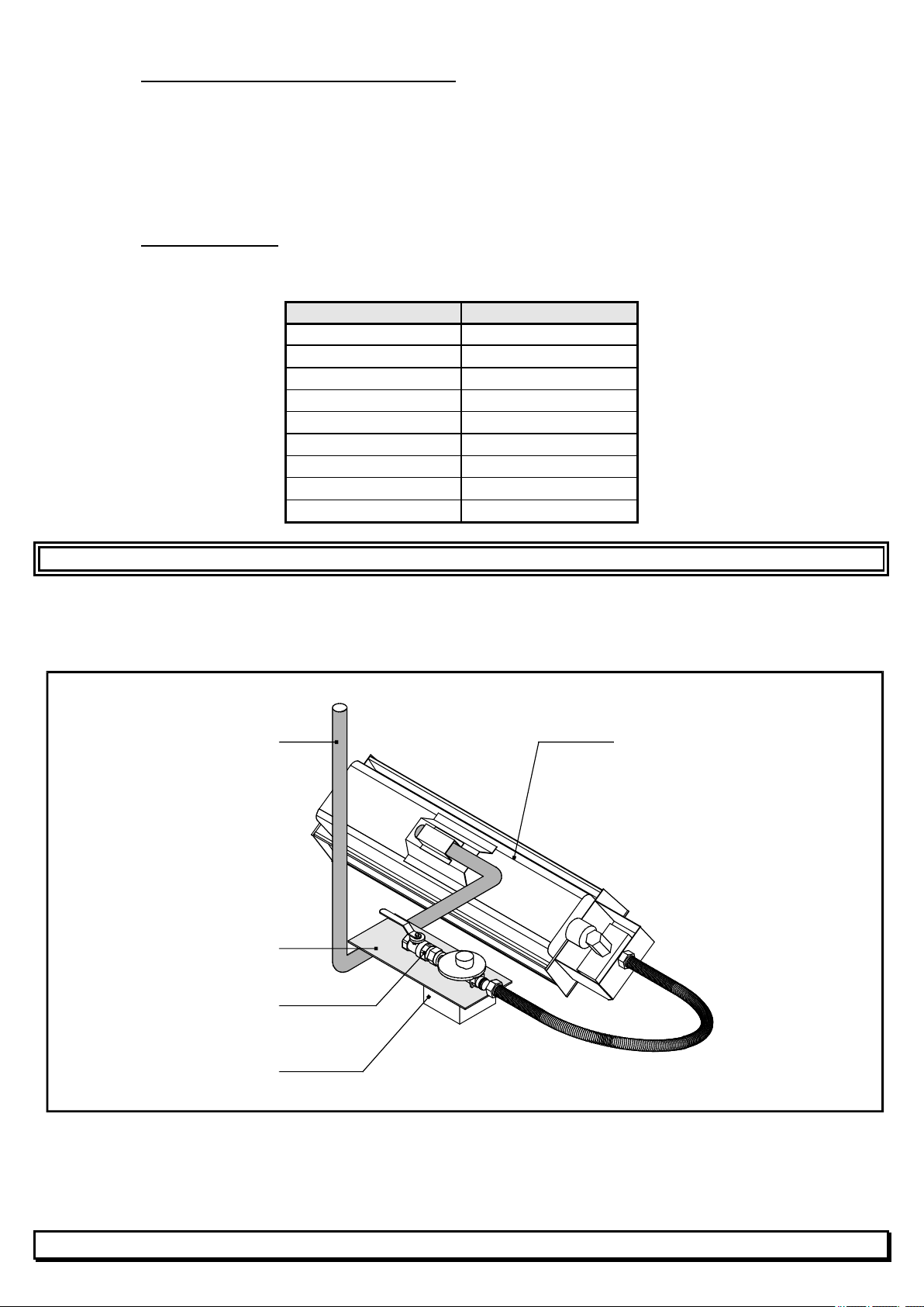
Examples of fixtures to be supplied by the installer:
FOR TYPE B6, B8, B10, B12 and B16 SX HEATERS
Steel tube 3/4"
(not supply by SBM)
Anchoring plate
(not supply by SBM)
Fixed regulator + valve
(not supply by SBM)
SBM infrared heater
RP3
(supplied by SBM)
5
Page 6
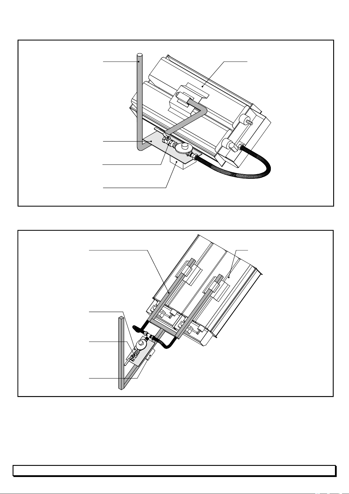
FOR TYPE B20, B20-2, B24, B24-2, B32 and B32-2SX HEATERS
Steel tube 3/4"
(not supply by SBM)
Anchoring plate
(not supply by SBM)
Fixed regulator + valve
(not supply by SBM)
RP3 or RP32
(supplied by SBM)
SBM infrared heater
FOR TYPE B64-2SX HEATERS
Steel tube 25x25 mm
(not supply by SBM)
Anchoring plate
(not supply by SBM)
Fixed regulator + valve
(not supply by SBM)
RP3 or RP32
(supplied by SBM)
SBM infrared heater
6
Page 7
HEATED
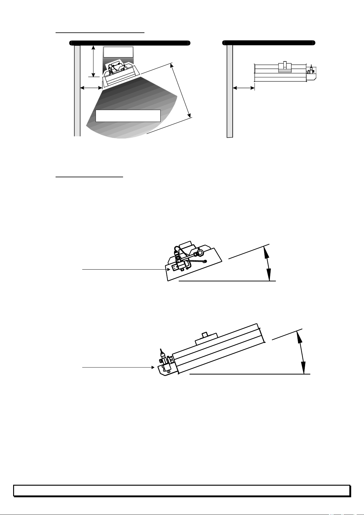
2.5 Minimum safety clearances (Inflammable materials :
= 70°C)
max
1 m
min.
0,6 m
min. (*)
(*) For minimum 20° inclination
AREA
HEATED AREA
2 m
min.
1 m
Min.
Where safety clearances cannot be respected, heat-protection must be provided above heater.
2.6 Inclination of heaters
In all cases, slope "P" or inclination "I" must be at least 10°.
Always install the automatic ignition block (BA block) in low position.
Lateral inclination "I".
BA BLOCK
IN LOW POSITION
P = 0°
I = 10 to 35°
Longitudinal inclination "P".
BA BLOCK
IN LOW POSITION
HORIZONTAL
I = 0°
P = 10 to 35°
HORIZONTAL
7
Page 8
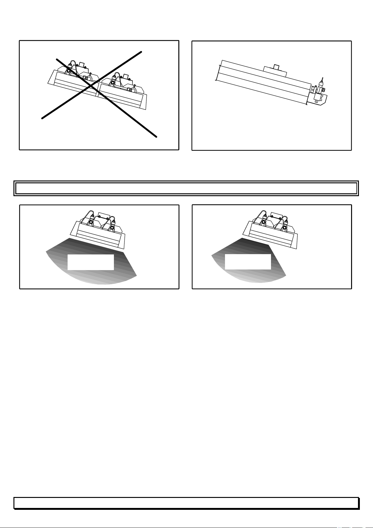
NO
YES
50%
100%
For B64-2SX
For B20-2SX, B24-2SX and B32-2SX with lateral inclination.
ALWAYS LIGHT THE TOP BURNER FIRST.
OPERATION
OPERATION
8
Page 9
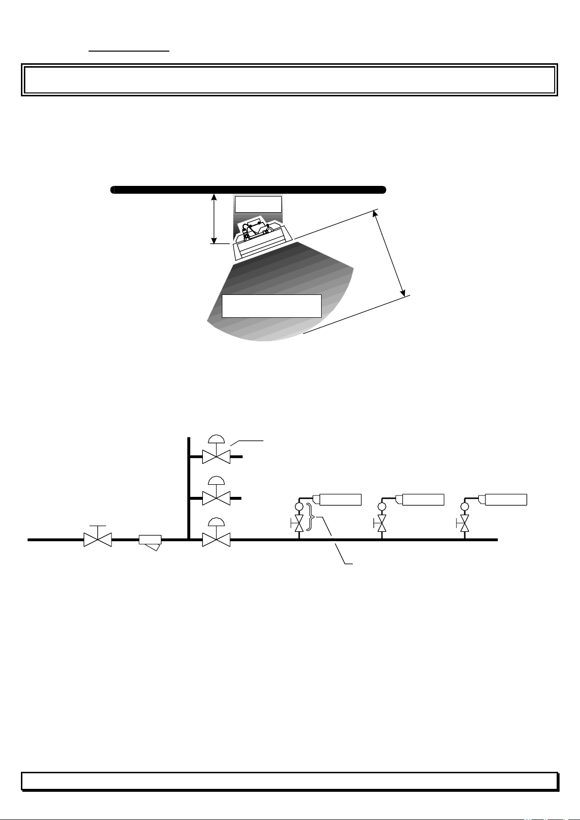
SOLENOID VALVE
NC
HEATED
HEATED
2.7 Gas connection
BEFORE INSTALLATION, CHECK THAT LOCAL CONDITIONS OF SUPPLY, GAS TYPE / PRESSURE AND
EQUIPMENT SETTINGS ARE COMPATIBLE.
Gas piping must not :
- be located in the heated area around a heater (see diagram below).
- produce any stress on the injector block. (Use preferably a metalic flex 12 Gf)
AREA
1 m
2 m
AREA
MEDIUM PRESSURE GAS SUPPLY
Gas supply pressure greater than the heater operating pressure
(see table on page 2).
(NC = Normally Closed)
SX HEATER
VALVE + GAS REGULATOR
GAS SUPPLY
MAIN VALVE
GAS FILTER
NC
NC
OR MAIN VALVE
9
Page 10
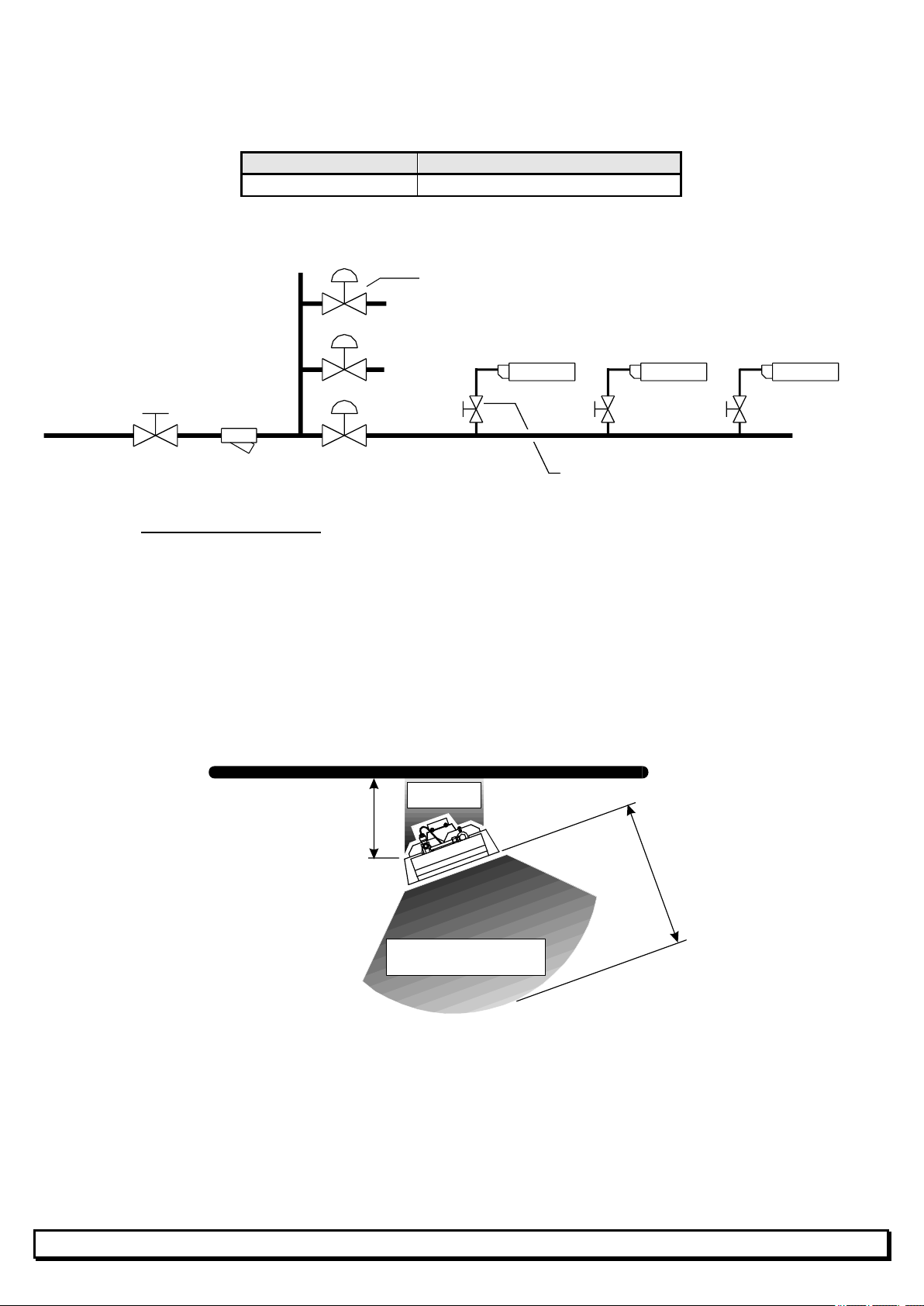
HEATED
HEATED
SOLENOID VALVE
NC
LOW PRESSURE GAS SUPPLY
The gas supply pressure is identical to the heater operating pressure
(see table on page 2).
GAS GAS SUPPLY PRESSURE
Air / Butane
37 mbar (*)
* acceptable total pressure loss : approx. 1 mbar.
NC
OR MAIN VALVE
(NC = Normally Closed)
GAS SUPPLY
MAIN VALVE
FILTER
NC
INDIVIDUAL VALVE
SX HEATER
2.8 Electrical connections
See diagram of a standard installation. (§2.2, page 4)
Use a NEUTRAL conductor or provide an ISOLATION TRANSFORMER.
All heaters must be properly GROUNDED.
Control : SX heaters are controlled by VisioLon Ind-T programmable controller.
Refer to the technical instructions.
Electric cables must not be located in the heated area around a heater.
(see diagram below)
AREA
1 m
2 m
AREA
10
Page 11
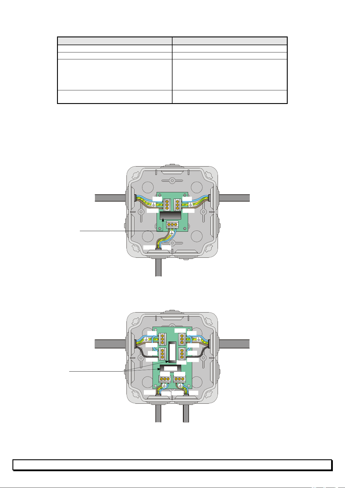
N/L1 Ph/L2
2
Ph/L2
2
N/L1 N/L1 Ph/L2 Ph/L2 Ph/L2 Ph/L2 N/L1 N/L1
N/L1 Ph/L2 N/L1 Ph/L2 Ph/L2 N/L1 N/L1 Fus50
50% 100% 50% 100%
Types of connection cable
LINK TYPE OF CABLE
Control unit to RP3 (and RP3 to RP3) 3 - conductor insulated with ground.
Control unit to RP32 (and RP32 to RP32) 5 - conductor insulated with ground.
RP3 and RP32 to heater Use the prewired plug supplied with the
heater
green/yellow wire: EARTH
blue wire: NEUTRAL
brown wire: LIVE
Control unit to sensor Use the sensor cable supplied by SBM.
(in 20m, 60m or 300m rolls)
Number of RP3 and RP32 units: 1 RP3 per type B6, B8, B10, B12, B16, B20,
B24 and B32 heater.
1 RP32 per type B20-2, B24-2, B32-2 and B64-2 heater.
Fixing RP3 and RP32 units: see instructions supplied in box.
Wire RP3’s as shown in the diagram below.
PRECEDING RP3
3x1.5 mm2
Fuse
SX HEATER
Wire RP32’s as shown in the diagram below.
PRECEDING RP32
4x1.5 mm2
Fus100
3x1.5 mm
4x1.5 mm
FOLLOWING RP3
FOLLOWING RP32
Fuses
50% 100%
2SX HEATER
11
Page 12
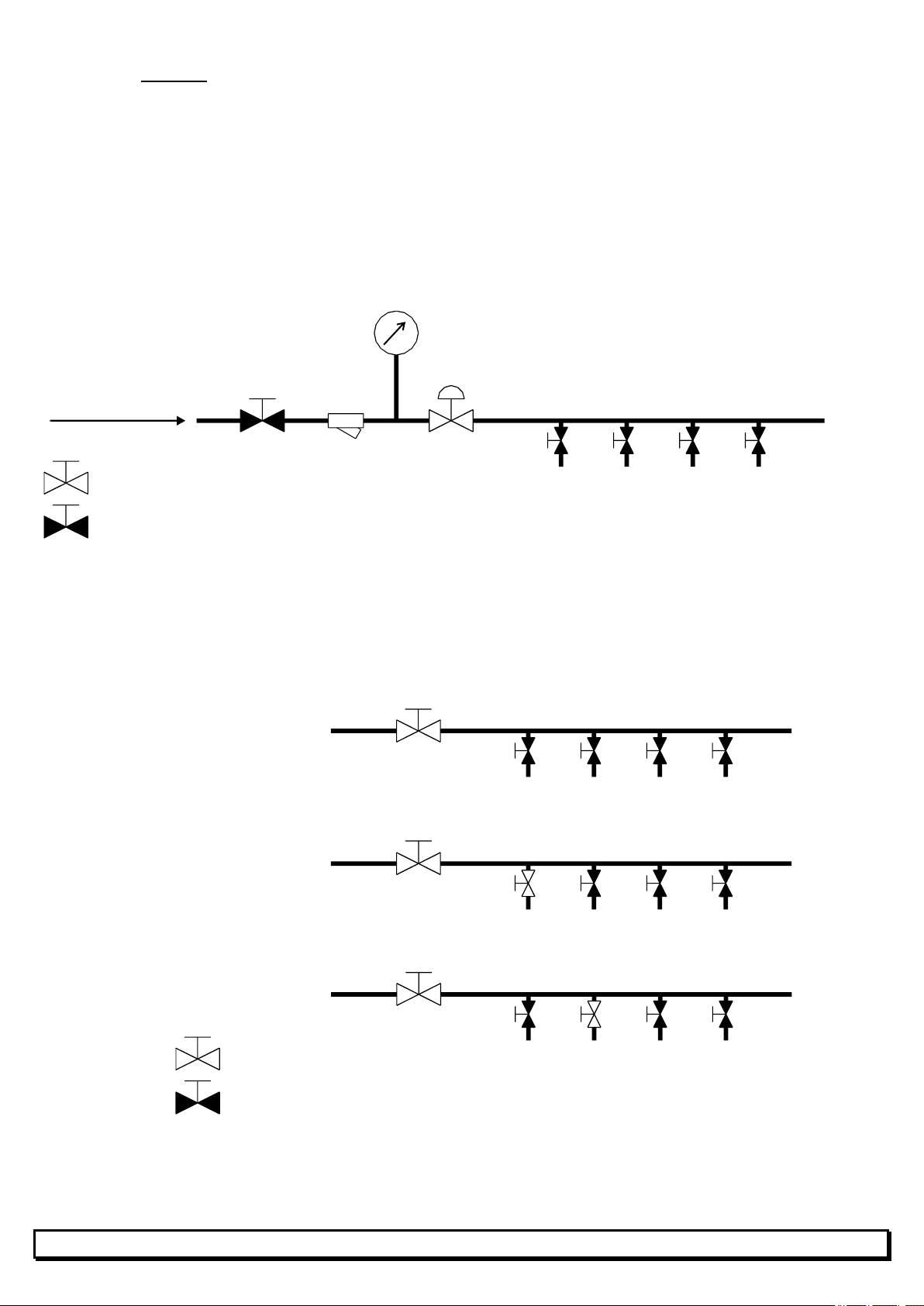
OPEN SOLENOID
2.9 Start-up
Gas-tightness test for industrial installations : (see diagram on next page)
a) Ensure that the installation is at a pressure (nitrogen or dry air) equal to 1.5 times the
gas operating pressure.
b) Turn off the nitrogen or dry air supply and wait 15 minutes for the pressure to stabilise.
c) Check the pressure on the pressure gauge.
d) After two hours, the pressure gauge needle must still show the same pressure.
e) If pressure has dropped, detect leaks , fix them and repeat the operation.
PRESSURE GAUGE
DRY AIR OR NITROGENE
= Open valve
= Closed valve
MAIN GAS VALVE
GAS FILTER
NC
VALVE
INDIVIDUAL VALVES OR FIXED REGULATORS + VALVES
TO HEATERS
Clean out
Aim: flush out impurities in gas piping
Clean out gas piping with dry air or, better, with nitrogen, AFTER DISCONNECTING ALL
ACCESSORIES.
PRESSURE ON
FLUSH OUT OUTLET Nr. 1
1
FLUSH OUT OUTLET Nr. 2
= Open valve
= Closed valve
2
12
Page 13

First start-up
a) Preliminary checks:
* calibration of control unit fuses.
* ground-fault breaker operation ("TEST" button).
b) Initial settings:
* main gas valve closed.
* individual valves open.
* ground-fault breaker set to "ON".
* thermostat or programmable controller set to correct temperature setting.
c) Ignition
* manual operation
- open the main gas valve.
- start the heater ignition cycle.
- if the flame is not lit after 45 seconds, start a second ignition cycle
- if the flame is still not lit or goes out, refer to chapter 5
(REPAIRS).
* automatic control
- open the main gas valve.
- check the settings (temperature, time).
- change module programming if required.
- run a full heating and cooling cycle and check:
. ignition cycle length (45 seconds maximum).
. ignition and shut-down of heaters according to temperature settings.
13
Page 14

3. RECEIPT OF INSTALLATION
TO BE PERFORMED BY THE INSTALLER IN THE PRESENCE OF THE CUSTOMER.
Check that the gas type and pressure comply with the type of heater installed
(see rating plate)
Check that an individual valve is installed prior to each heater.
Check that the "SX USER GUIDE" (Manual operation or Automatic control) is displayed next to
the control unit, after being stamped by the installer.
Provide the customer with a copy of each SX USER INSTRUCTIONS supplied in the product
boxes.
Indicate to the customer the locations of:
- valves.
- electric switches.
- control units.
Explain to the customer how all control units operate.
Plan the initial maintenance visit (1 year after start-up).
14
Page 15
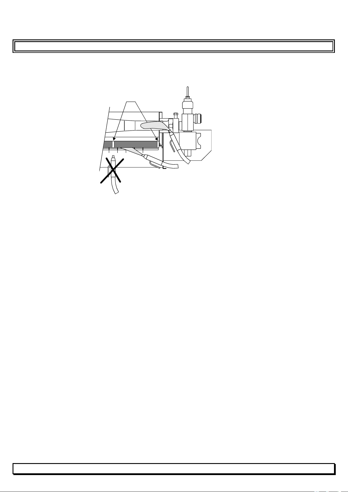
4. MAINTENANCE
LIST OF OPERATIONS TO BE PERFORMED DURING THE ANNUAL MAINTENANCE VISIT.
Removal of dust from heaters
- on site, without disassembly, heaters off and cold.
JOINTS
COMPRESSED AIR :
3 to 5 bar MAX.
DO NOT BLOW AIMING AT JOINTS
Check condition of ceramic plates (visual inspection).
Check heater fixture.
Check tightness of accessories.
Check heater operation.
Switch on all heaters, check ignition and combustion. A combustion temperature of
approximately 900°C (uniform orange red colour) ensures heater cleanliness and correct
gas supply pressure.
Check operation of solenoid valves.
Check that all solenoid valves properly close (heaters switched off).
Check controls.
Check all settings (do not forget anti-freeze setting).
BETWEEN CERAMIC PLATES
15
Page 16
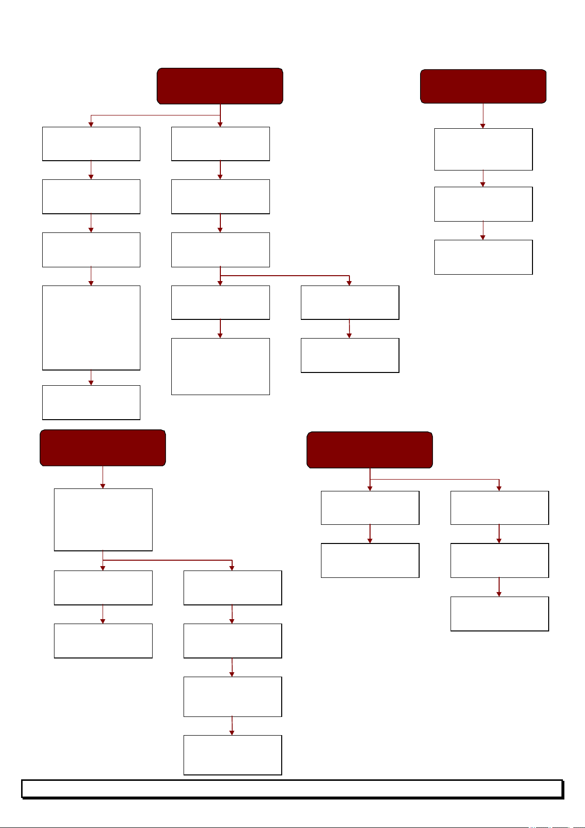
ONE HEATE
R
DOES NOT LIGHT
Spark
RP32 fuse
Check cleanness of :
Replace BA block
ONE HEATER IS NOT
HOT ENOUGHT (<850°C)
(OR STUTTERING FLAME)
an adjustable
a fixed
Check cleanness of :
If adjusting is
impossible, check
inlet pressure
inlet pressure is
correct, replace
ONE HEATER IS
TOO HOT (>950°C)
Heater operating with
an adjustable
Heater operating with
a fixed
Replace the
If adjusting is
impossible, replace
to pressure test point
5. REPAIRS
Problems on a single heater.
ONE HEATER LIGHTS
AND GOES OUT AFTER
45 seconds
No spark
Check RP3 -
Check screw tightness
of prewired plug
Check igniter :
- wire
- ceramic
- distance between
earth- pin and igniter
( 5 mm )
- connection to
BA block
Check individual valve
(open?)
Check gas flow throught
the injector block
(«click» ?)
«click»
- regulator/governor
gas inlet filter
- heater gas inlet filter
- injector(s)
No «click»
Replace BA block and
(or) injector block
Check that
thermocouple is
properly tightened
Replace the rmocouple
Repla ce inje ctor block
- regulator/governor
inlet gas filter
- heater inlet gas filter
- injector(s)
- heater
Heater operating with
regulator/governor
Replace the
regulator/governor
Heater operating with
regulator/governor
Check injection pressure
to pressure test point
(see pages 2 and 3)
regulator/governor
regulator/governor
regulator/governor
regulator
regulator/governor
Check injection pressure
(see pages 2 and 3)
the regulator/governor
If regulator/governor
regulator/governor
16
Page 17
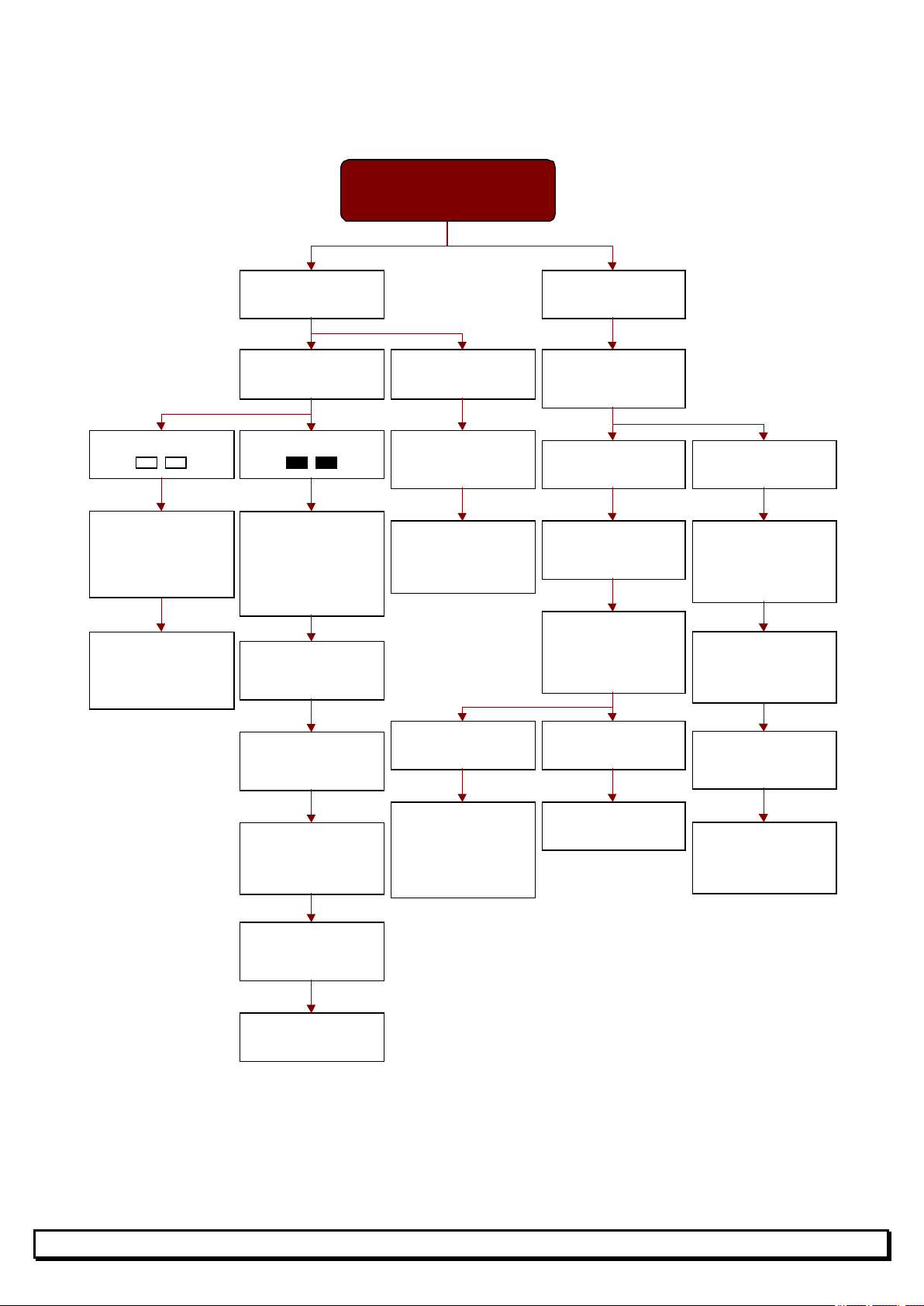
First, check compatibility of heaters with the
A GROUP OF HEATERS
solenoid valves output
Problems on a group of heaters.
Check setpoint and
programming of the
module
Safety switch
activated or
Override ON
with mode OFF :
Heating off
No spark
Control module
ON
Module displays :Module displays :
Check module heaters
output voltage (230V)
during ignition cycle
(45 seconds)
If no voltage, replace
module
DO NOT LIGHT
Control module
OFF
Check power supply
(Main breaker)
If module is supplied,
replace module
gas type and pressure.
Spark
Check main gas valve
open
Solenoid valve open
Check gas tank or
gas supply pressure
Check gas flow
throught the injector
blocks
("click" ?)
Solenoid valve closed
Check module
voltage (230V)
If no voltage, replace
module
Check voltage at first
RP3-RP32 input
If no voltage, check :
- electrical cable
- connections
Check RP3-RP32
fuses
Replace BA blocks
«click»
Check cleanness of :
- main gas filter
- solenoid valves
- regulators/governors
gas inlet filters
No «click»
Replace BA blocks
Check voltage at
solenoid valve
If solenoid valve is
supplied, replace it
17
Page 18
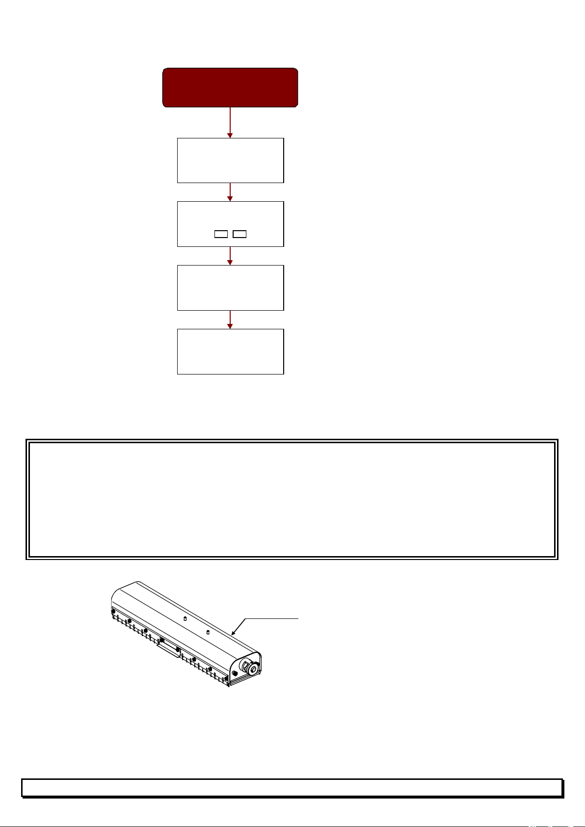
WITH ALL SPARE PART ORDERS, PLEASE INDICATE:
eck that the temperature setting is lower than
Problems on a group of heaters (cont.).
A GROUP OF HEATERS
DO NOT STOP
Check se tpoint a nd
programming of the
module
Check module set to
OFF :
MT = - MTH = 0%
Check ze ro voltage at
solenoid valve module
output
First, ch
ambient temperature.
Check solenoid valve :
- orientation
- clea nness
- operation
SX heater spare parts.
- Type / serial number of the heater.
- Gas type.
- Operating pressure.
ALL THIS INFORMATION CAN BE FOUND ON THE RATING PLATE ON THE
HEATER.
Burner
18
Page 19
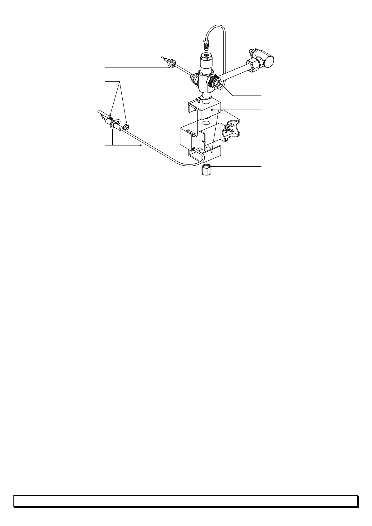
Thermocouple
Earth pin
Igniter
6. CHANGING THE GAS USED
For all changes in the gas used, contact your SBM agent.
Injector block
BA block brackets (X 2)
BA block
Anchoring nut
19
 Loading...